EP2294721B1 - Managing coexistence among signaling protocols on a shared medium - Google Patents
Managing coexistence among signaling protocols on a shared medium Download PDFInfo
- Publication number
- EP2294721B1 EP2294721B1 EP09794925.9A EP09794925A EP2294721B1 EP 2294721 B1 EP2294721 B1 EP 2294721B1 EP 09794925 A EP09794925 A EP 09794925A EP 2294721 B1 EP2294721 B1 EP 2294721B1
- Authority
- EP
- European Patent Office
- Prior art keywords
- devices
- subset
- signal
- ipp
- signals
- Prior art date
- Legal status (The legal status is an assumption and is not a legal conclusion. Google has not performed a legal analysis and makes no representation as to the accuracy of the status listed.)
- Active
Links
Images


Classifications
-
- H—ELECTRICITY
- H04—ELECTRIC COMMUNICATION TECHNIQUE
- H04B—TRANSMISSION
- H04B7/00—Radio transmission systems, i.e. using radiation field
- H04B7/24—Radio transmission systems, i.e. using radiation field for communication between two or more posts
- H04B7/26—Radio transmission systems, i.e. using radiation field for communication between two or more posts at least one of which is mobile
- H04B7/2643—Radio transmission systems, i.e. using radiation field for communication between two or more posts at least one of which is mobile using time-division multiple access [TDMA]
- H04B7/2656—Radio transmission systems, i.e. using radiation field for communication between two or more posts at least one of which is mobile using time-division multiple access [TDMA] for structure of frame, burst
-
- H—ELECTRICITY
- H04—ELECTRIC COMMUNICATION TECHNIQUE
- H04B—TRANSMISSION
- H04B3/00—Line transmission systems
- H04B3/54—Systems for transmission via power distribution lines
Definitions
- the invention relates to managing coexistence among signaling protocols on a shared medium.
- a network of communication devices can share a communication medium (e.g., wires connecting multiple devices) using any of a variety of techniques.
- Some networks include mechanisms that enables various devices and systems to coexist sharing communication resources (e.g., frequency and time) when installed in a network with common electrical wiring.
- WO 2007/043705 A1 discloses a communication apparatus which repeatedly outputs a first multi-carrier signal SS during predetermined periods T1, T2, T3,..., and outputs a second multi-carrier signal RS whose phase vector is different from that of the first multi-carrier signal SS, at a predetermined timing based on the first multi-carrier signal SS.
- the communication apparatus further detects the second multi-carrier signal RS output from another communication apparatus, which uses a different communication method from the communication apparatus. Accordingly, both communication apparatuses can differentiate the first multi-carrier signal SS from the second multi-carrier signal RS without performing relatively cumbersome modulation and other processes.
- US 2007/025398 A1 discloses a method and system for communicating between stations in a network.
- the method includes providing repeated beacon transmissions from a coordinator station for coordinating transmissions among the stations; transmitting a signal from a first station and receiving the signal at a second station; and performing one or both of generating the signal based on a local clock at the first station and time adjustment information in a beacon transmission received by the first station, and sampling the signal at sample times based on a local clock at the second station and time adjustment information in a beacon transmission received by the second station.
- a method for communicating among multiple devices over a shared communication medium includes, in a schedule among multiple subsets of the devices that includes at least one respective time slot for each subset, transmitting from at least one of the devices in a given subset a presence signal associated with the given subset within a time slot for the given subset.
- a presence signal associated with a given subset is configured to indicate the presence of at least one device in the given subset.
- the method also includes communicating among devices in a given subset based on presence signals detected from one or more devices in at least one different subset.
- aspects can include one or more of the following features.
- Respective presence signals associated with different subsets are unique.
- Respective presence signals associated with different subsets include multiple carrier frequencies modulated using a unique sequence of phases.
- the sequence of phases comprises a sequence of two phase values that differ by 180 degrees.
- the sequence of phases is determined from a stored list of phases starting at a given offset, where each unique sequence of phases starts at a different offset.
- the schedule is a recurring schedule in which the time slots are synchronized to an alternating current line cycle on the shared communication medium.
- the time slots are at different predetermined offsets from a zero crossing of the alternating current line cycle.
- the predetermined offsets are in proximity to the zero crossing of the alternating current line cycle.
- the time slots each include time reserved for one of the presence signals and time margins on either side that enable one of the presence signals to be identifiable when the zero crossing is not accurately detected.
- devices that are not transmitting presence signals scan for presence signals.
- the method further includes synchronizing to a detected zero crossing at a device in a first subset in response to receipt of a resynchronization signal from a device in a second subset different from the first subset.
- the resynchronization signal is transmitted from the device in the second subset in a time slot following a time slot in which a presence signal is transmitted from the device in the first subset.
- the device in the second subset transmits the resynchronization signal in response to an indication from at least one device that one or more presence signals are out of synchronization.
- a presence signal is out of synchronization if it is detected outside of a time slot for a subset with which the presence signal is associated.
- the schedule includes at least one presence signal time slot for each subset and time intervals including communication time slots allocated for communicating among devices in a given subset.
- the method further includes requesting to share the time intervals among devices of different subsets using either time division multiplexing or frequency division multiplexing based on signals sent during the time slots.
- a device rejects a request to use frequency division multiplexing to select use of time division multiplexing to share the time intervals among devices of different subsets.
- Presence signals sent by devices of at least one subset are coordinated by a master device for that subset.
- the method further includes devices in a subset communicating detected presence signal information to the master for that subset.
- At least one device in a subset transmits presence signals for that subset.
- Multiple devices in a subset transmit presence signals for that subset.
- All devices in a subset transmit presence signals for that subset.
- the identical presence signals add constructively so that the identical presence signals are distinguishable from presence signals transmitted by devices in other subsets.
- the presence signal time slots for transmitting presence signals are separated by time intervals including communication time slots allocated for communicating among devices in a given subset.
- Time slots are assigned to a given subset based on subsets identified by the presence signals.
- a first time slot assigned to a first subset and a second time slot assigned to a second subset are separated by a silence margin.
- the method further includes assigning time slots to subsets based on at least one of latency and throughput.
- Time slots are assigned for a given subset spread over most of the time interval to provide low latency.
- Time slots are assigned for a given subset contiguously within the time interval to provide high throughput.
- the method further includes a device in a first subset using a time slot assigned to a second subset when no device in the second subset communicates during one or more slots previously assigned to the second subset.
- a device in the first subset requests permission from a master device before using the time slot assigned to the second subset.
- a device in the first subset uses the time slot assigned to the second subset after determining that a signal to noise ratio suggests interference with a device in the second subset is improbable.
- a device in a first subset requests use of all of the time slots in a given interval for use by one or more devices in the first subset.
- Devices in different subsets use signals that overlap in their spectra.
- At least one of the subsets utilizes orthogonal frequency-division multiplexing.
- a system in another aspect, in general, includes: a communication medium; a first subset of devices coupled to the communication medium; and a second subset of devices coupled to the communication medium. At least one of the devices in a given subset of multiple subsets of devices, including at least the first and second subsets of devices, is configured to: transmit a presence signal associated with the given subset within a time slot for the given subset according to a schedule that includes at least one respective time slot for each subset, where a presence signal associated with a given subset is configured to indicate the presence of at least one device in the given subset, and communicate among other devices in the given subset based on presence signals detected from one or more devices in at least one different subset.
- the techniques provide unique signals for different systems transmitted in a round-robin fashion that enables efficient detection of the different systems. These signals also enable the coexistence procedures to be resilient to errors in tracking time references associated with local powerline signal features (e.g., a local zero crossing). For example, since each signal is unique various devices will not get confused if there are significant AC zero crossing offsets between different systems.
- the techniques enable low cost zero cross detectors. For example, low cost zero cross detectors may not actually track the exact zero cross location but may track a fixed location with respect to the zero cross. Devices may differ in their interpretation of the zero cross but they can still synchronize by measuring the offset at which the unique signal comes relative to their local zero cross.
- phase shifts e.g., from capacitive or inductive loads
- system locations e.g., different homes.
- systems can operate independently and do not have to share bandwidth with networks that are far enough to not cause significant interference.
- FIG. 1 shows an exemplary network configuration for an access network 100 such as a Broadband Power Line Network (BPLN) that provides access to a backhaul network.
- BPLN Broadband Power Line Network
- a BPLN can be managed by a service provider entity having access to the underlying physical power line medium.
- a BPLN is a general purpose network that can be used for several types of applications including, smart grid management, broadband internet access, voice and video delivery services, etc.
- a BPLN can be deployed on low voltage, medium voltage and high voltage power lines.
- a BPLN can span an entire neighborhood or it may be deployed within a single multi-dwelling unit. For example, it can be used to provide network service to tenants in a single apartment building. While power lines are one medium for deploying the BPLN, similar techniques can be deployed on other wire lines, such as, for example, coaxial cables, twisted pair or a combination thereof.
- a BPLN can include one or more Cells.
- a cell is a group of broadband power line (BPL) devices in a BPLN that have similar characteristics such as association management, security, Quality of Service (QoS) and channel access settings, for example.
- BPL broadband power line
- QoS Quality of Service
- Cells in a BPLN are logically isolated from each other, and communication to and from the backhaul occurs within the cell.
- Each cell in a BPLN includes a Core-Cell and may also include one or more Sub-Cells. There can be more than one cell on a given physical power line medium.
- Some Cells may use different protocols, including different PHY protocols.
- an In-Home AV Sub-Cell may use an In-Home AV PHY protocol
- an Access BPL Sub-Cell may use an Access BPL PHY protocol.
- the techniques described herein can be used to enable Cells using different PHY protocols to coexist in the network 100.
- a Core-Cell includes a group of devices in a BPLN that can share certain functionality such as a common security protocol.
- An exemplary Core-Cell includes a Head End (HE), Repeaters (R), and Network Termination Units (NTUs), but may exclude Customer Premise Equipment (CPE).
- the Head End (HE) is a device that bridges a cell to the backhaul network. At a given time, a cell will have one active Head End and the Head End manages the cell including the Core-Cell and any associated Sub-Cells.
- a Repeater (RP) is a device that selectively retransmits MSDUs to extend the effective range and bandwidth of the BPLN Cell. Repeaters can also perform routing and QoS functions.
- the NTU is a device that connects a BPLN cell to the end users' network or devices.
- the NTU may in some cases bridge to other network technologies such as WiFi.
- a single NTU can serve more than one customer.
- Each Sub-Cell is associated with an active NTU.
- an HE, an NTU and/or an RP can be co-located at a single station.
- a single device may be designed to perform multiple functions. For example, a single device can simultaneously be programmed to perform the tasks associated with an RP and an NTU.
- CPE devices e.g., a computer
- endpoint devices can communicate with other devices in the network through the NTU, any number of repeaters, (e.g., including no repeaters), and the Head End.
- Each device in the network communicates as a communication "station” using a PHY layer protocol that is used by the devices to send transmissions to any other devices that are close enough to successfully receive the transmissions.
- Devices that cannot directly communicate with each other use one or more repeater devices to communicate with each other. The devices have the potential to interfere with each other, but techniques can be used to coordinate in a centralized and/or distributed manner.
- a "MAC Service Data Unit” (MSDU) is a segment of information received by the MAC layer.
- the MAC layer can process the received MSDUs and prepares them to generate "MAC protocol data units" (MPDUs).
- An MPDU is a segment of information including a header (e.g., with management and overhead information) and payload fields that the MAC layer has asked the PHY layer to transport.
- An MPDU can have any of a variety of formats based on the type of data being transmitted.
- a “PHY Protocol Data Unit (PPDU)” refers to the modulated signal waveform representing an MPDU that is transmitted over the power line by the physical layer.
- the MAC layer can provide several functions including channel access control, providing the required QoS for the MSDUs, retransmission of corrupt information, routing and repeating.
- Channel access control enables devices to share the powerline medium.
- CSMA/CA carrier sense multiple access with collision avoidance
- TDMA Time Division Multiple Access
- TDMA distributed TDMA
- token based channel access etc.
- PHY Physical layer
- FEC Forward error correction
- Each symbol has a predetermined time duration or symbol time T s .
- Each symbol is generated from a superposition of N sinusoidal carrier waveforms that are orthogonal to each other and form the OFDM carriers.
- Each carrier has a peak frequency f i and a phase ⁇ i measured from the beginning of the symbol.
- f i peak frequency
- ⁇ i phase ⁇ i measured from the beginning of the symbol.
- ⁇ i For each of these mutually orthogonal carriers, a whole number of periods of the sinusoidal waveform is contained within the symbol time T s .
- the phases ⁇ i and amplitudes A i of the carrier waveforms can be independently selected (according to an appropriate modulation scheme) without affecting the orthogonality of the resulting modulated waveforms.
- the carriers occupy a frequency range between frequencies f 1 and f N referred to as the OFDM bandwidth.
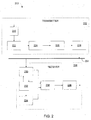
- a communication system 200 includes a transmitter 202 for transmitting a signal (e.g., a sequence of OFDM symbols) over a speciuncation medium 204 to a receiver 206.
- the transmitter 202 and receiver 206 can both be incorporated into a network interface module at each station.
- the communication medium 204 can represent a path from one device to another over the power line network.
- modules implementing the PHY layer receive an MPDU from the MAC layer.
- the MPDU is sent to an encoder module 220 to perform processing such as scrambling, error correction coding and interleaving.
- the encoded data is fed into a mapping module 222 that takes groups of data bits (e.g., 1, 2, 3, 4, 6, 8, or 10 bits), depending on the constellation used for the current symbol (e.g., a BPSK, QPSK, 8-QAM, 16-QAM constellation), and maps the data value represented by those bits onto the corresponding amplitudes of in-phase (I) and quadrature-phase (Q) components of a carrier waveform of the current symbol.
- any appropriate modulation scheme that associates data values to modulated carrier waveforms can be used.
- PN Pseudo Noise
- the mapping module 222 also determines the type of modulation to be used on each of the carriers (or "tones") according to a "tone map.”
- the tone map can be a default tone map, or a customized tone map determined by the receiving station, as described in more detail below.
- An inverse discrete Fourier transform (IDFT) module 224 performs the modulation of the resulting set of N complex numbers (some of which may be zero for unused carriers) determined by the mapping module 222 onto N orthogonal carrier waveforms having peak frequencies f 1 ,..., f N .
- IDFT inverse discrete Fourier transform
- the discrete Fourier transform corresponds to a fast Fourier transform (FFT) in which N is a power of 2.
- a post-processing module 226 combines a sequence of consecutive (potentially overlapping) symbols into a "symbol set" that can be transmitted as a continuous block over the communication medium 204.
- the post-processing module 226 prepends a preamble to the symbol set that can be used for automatic gain control (AGC) and symbol timing synchronization.
- AGC automatic gain control
- the post-processing module 226 can extend each symbol with a cyclic prefix that is a copy of the last part of the symbol.
- the post-processing module 226 can also perform other functions such as applying a pulse shaping window to subsets of symbols within the symbol set (e.g., using a raised cosine window or other type of pulse shaping window) and overlapping the symbol subsets.
- An Analog Front End (AFE) module 228 couples an analog signal containing a continuous-time (e.g., low-pass filtered) version of the symbol set to the communication medium 204.
- the effect of the transmission of the continuous-time version of the waveform S ( t ) over the communication medium 204 can be represented by convolution with a function g ( ⁇ ; t ) representing an impulse response of transmission over the communication medium.
- the communication medium 204 may add noise n ( t ), which may be random noise and/or narrowband noise emitted by a jammer.
- modules implementing the PHY layer receive a signal from the communication medium 204 and generate an MPDU for the MAC layer.
- An AFE module 230 operates in conjunction with an Automatic Gain Control (AGC) module 232 and a time synchronization module 234 to provide sampled signal data and timing information to a discrete Fourier transform (DFT) module 236.
- AGC Automatic Gain Control
- DFT discrete Fourier transform
- the receiver 206 feeds the sampled discrete-time symbols into DFT module 236 to extract the sequence of N complex numbers representing the encoded data values (by performing an N -point DFT).
- Demodulator/Decoder module 238 maps the complex numbers onto the corresponding bit sequences and performs the appropriate decoding of the bits (including de-interleaving and descrambling).
- modules of the communication system 200 including modules in the transmitter 202 or receiver 206 can be implemented in hardware, software, or a combination of hardware and software.
- Communication systems that use different physical layer (PHY) protocols can coexist on a communication medium (e.g., a powerline medium) by using an Inter-PHY Protocol (IPP).
- IPP Inter-PHY Protocol
- the different protocols may use different signal modulation schemes but still may have some features in common.
- the different protocols may be compliant with a common set of guidelines or a common specification (e.g., the IEEE 1901 Specifications).
- the IPP includes a resource sharing mechanism that regulates access to the communication medium by devices functioning as communication devices (for example, devices communicating over a power line).
- a subset of devices that communicate among each other form a logical network that shares the medium with other logical networks that use either the same PHY protocol or a different PHY protocol.
- One or more subsets of stations using the same PHY protocol may be spread throughout a physical network such that the subsets (even if they do not all communicate with each other) together form a logical "communication system" that shares the medium with other communication systems that use different PHY protocols.
- Subsets of stations that share the same PHY protocol may be referred to as belonging to the same System Category.
- different subsets of devices use different PHY protocols but may use a common medium access control (MAC) protocol.
- MAC medium access control
- an IPP provides resource sharing among one or more subsets of access (AS) devices and one or more subsets of in-home devices (IH) that have the P1901 common MAC and either the Wavelet OFDM IEEE 1901 PHY or the Windowed FFT OFDM IEEE 1901 PHY.
- Some Coexistence Protocols (CXPs) defined in some coexistence specifications use a more general resource sharing mechanism that allows non-IEEE 1901 devices to share efficiently resources with each other and with IEEE 1901 devices.
- IPP is compatible with some other forms of CXP protocols.
- a BPL system is a communcation system using the powerline as a medium to transmit and receive information.
- the BPL system may consist of one master device and one or more slave devices.
- IPP provides resource sharing between an Access System Category (AS also called "A"), and in-home systems (IH).
- AS Access System Category
- IH in-home systems
- the in-home systems may belong to the Wavelet OFDM PHY System Category (IH-W also called "W") or using the Windowed OFDM PHY System Category (IH-O also called "O").
- the IPP handles the situation when multiple System Categories are in range of each other, i.e. when one or more devices of a System Category can interfere with one of more devices of a different System Category.
- the protocol coordinates coexistence between an access system and one or more in-home systems, regardless of the PHY as well as coexistence among different in-home systems utilizing different IEEE 1901 PHYs.
- the IPP can define a set of policies for regulating resource sharing. For example, when both Access System Categories and In-Home System Categories are in range of each other, the defined policies may allocate that 50% of the channel resources be available to the Access System Category and 50% of the channel resources be available to all the In-Home System Categories. In another example, when only an In-Home System Categories are in range of each other, the defined policies may direct channel resources be shared equally; thus, 50% of channel resources be assigned to a System Category that uses the Windowed FFT OFDM and 50% of channel resources will be assigned to System.Category that uses the Wavelet OFDM PHY.
- devices within a System Category indicate their presence by transmitting a predetermined unique presence signal.
- a predetermined unique presence signal For example, an exemplary waveform used as these presence signals is a Commonly Distributed Coordination Function (CDCF) signal defined below.
- the CDCF signal may be transmitted by all systems including when only one System Category is present.
- devices sharing the same medium are able to determine the network status, which indicates the System Categories that are in interference range. Depending on the network status, different resource allocations will be carried out.
- a CDCF signal is transmitted during an IPP Window, a region of time used by devices for transmitting/detecting one or more CDCF signals.
- the IPP Window occurs periodically, for example, the period may be a multiple of the line cycle in a BPL system.
- the IPP Window may occur alone or immediately followed by a CXP Window and the IPP Window and CXP window are further divided into several time slots called Fields.
- the Inter PHY Protocol may be used to coordinate communication between an Access system category (A), an In Home Wavelet OFDM PHY system category (W), and an In Home Windowed OFDM PHY system category (O).
- A Access system category
- W In Home Wavelet OFDM PHY system category
- O In Home Windowed OFDM PHY system category
- IPP there are two IPP fields 302, 304 within the IPP Window 306 and multiple CXP Fields 308 within the CXP Window 310.
- the IPP Window 306 occurs every Allocation Period T ipp 312, whereas the CXP Window 310 occurs every three Allocation Periods 312.
- the CXP Fields 308 are used by the co-existence protocol (CXP) and are ignored by the IPP.
- CXP co-existence protocol
- devices detect IPP Fields 304, and optionally detect CXP fields 308. In some arrangements, during the IPP Window 306 as well as during the CXP Window 310, no device transmits anything except the appropriate CDCF signals.
- the IPP window occurs at a fixed offset T ⁇ ff 314 relative to the underlying line cycle zero crossing. Since there are two zero crossings in a cycle and there are often up to three sections of wiring with different phases for their respective line cycles in a building, there are actually six possible zero crossings instances. Synchronization techniques allow all devices in range of each other to synchronize to a common zero crossing instance.
- every System Category uses an IPP window in a round robin fashion.
- Access system category devices use an IPP window 402
- In-Home Wavelet OFDM System category devices use the subsequent IPP window 404
- In-Home Windowed OFDM system category devices use the next IPP Window 406, and so on in a round robin fashion.
- all devices that belong to the same System Category will transmit CDCF signals simultaneously in the IPP window assigned to their System Category. Every device will transmit CDCF signals in its IPP Window every three T ipp cycles. Every device will detect CDCF signals in the other two IPP Windows every T ipp to assess the Network Status. Every device, when not engaged in an active link with another device, will also continuously scan for CDCF signals outside the IPP Windows systems to detect the presence of other unsynchronized devices. If unsynchronized devices are detected, a re-synchronization procedure is started (to enable devices to synchronize to a common zero crossing instance).
- a device that is the only device belonging to a system category may detect unsynchronized devices and system categories while the device is not transmitting.
- the device does not send CDCF signals inside the IPP Window but scans for CDCF signals continuously outside the IPP Windows to detect the presence of unsynchronized systems.
- a device that it is connected to the Access network but it is alone regarding the In-Home side scans continually outside the IPP Window for unsynchronized devices on the In-Home side.
- IPP Period the network status every three T ipp cycles
- the devices are able to update the network status every T ipp cycle.
- the network status of a device is determined by the system categories that are present on the shared medium and that can be detected by the device using the CDCF signals detected.
- CDCF signals are not transmitted in the IPP Window assigned to the Access system category 408, thus indicating that no devices belonging to an Access system category are detected.
- a device can detect the presence of all system categories since the device can detect CDCF signals that are transmitted in all three consecutive IPP windows 402, 404, 406.
- the Network Status indicates the presence of at least a device belonging to the Access (AS), In-Home Windowed (IH-0), and In-Home Wavelet OFDM (IH-W) system categories.
- AS Access
- IH-0 In-Home Windowed
- IH-W In-Home Wavelet OFDM
- an allocation period 502 lasts T ipp seconds and includes an IPP Window 512 and a time interval including time slots allocated for the devices within a given System Category to communicate with each other.
- This time interval allocated for communication can be shared among multiple System Categories using Time Division Multiplexing (TDM), for example, within each of four Time Division Multiplexing Units (TDMUs) 504.
- TDM Time Division Multiplexing
- TDMUs Time Division Multiplexing Units
- FDM Frequency Division Multiplexing
- the duration of a TDMU 504 may be equal to two power line cycles 506, and each TDMU 504, 510 may be further sub-divided into time slots called TDM slots 508 (TDMS), in this case eight TDMS within one TDMU.
- the duration of a TDMS may be defined by the duration of the power line cycle. For example, a 50 Hz power line cycle results in a TDMS duration of 5 milliseconds while a 60 Hz power line cycle results in a TDMS duration of 4.166 milliseconds.
- a TDMS is exclusively assigned to all the systems belonging to the same System Category and the allocation policy will be based on the network status.
- the IPP Window 512 occurs at the beginning of TDMU #0 510 and IPP fields 602, 604 are present in every IPP window 512 whereas CXP Fields 606 are present only during the IPP window 512 assigned to the Access system categories 510. Therefore, the IPP window 512 occurs with a periodicity of one T ipp equal to four TDMUs, whereas the CXP window occurs with a periodicity of three T ipp equal to twelve TDMUs.
- FIG. 6 shows one arrangement where the solid lines denote fields where CDCF signals are always transmitted if devices belonging to the appropriate System Category are present. Dashed lines denote fields where CDCF signals may or may not be present.
- every IPP window is used in exclusivity by the devices that belong to a specific system category. For example, A, W, and O.
- the only exception is during the re-synchronization procedure when any system may transmit the CDCF signal in the second field of any system category (for example, the second field of an In-Home system category 610, 614).
- the first IPP window is used only by the devices that belong to the Access system category.
- IPP Field 1 602. The second IPP Field 604 is used to indicate resource needed or the request for TDM/FDM sharing policy and is called the IPP Access Auxiliary Field. If there is no Access system category present, no CDCF signals are transmitted in the IPP fields.
- Each IPP Field may contain a CDCF signal sent using any of a multiple sets of phases (e.g., the phases described above for different carriers). In one arrangement there are four potential sets of phases with which CDCF signals may be sent. The set of phases with which the CDCF signal is sent may be used to communicate additional information. For example, in one arrangement CDCF signals sent in the first 602 and second 604 IPP fields of the A IPP Window are used with the following meaning:
- the second IPP window is used by the devices belonging to the In-Home Wavelet OFDM (W) system category. If there is a W system using the channel, all its devices transmit a CDCF signal to indicate their presence in IPP Field 1 608, using the CDCF signal with a set of phases labeled "Phase P2."
- the second IPP Field 610 may be used during the re-synchronization procedure and may be used to indicate lack of FDM capability. If there is no W present, no CDCF signals are transmitted in the IPP fields of this IPP Window.
- the first 608 and second 610 IPP fields of the W IPP Window may be used to convey the following meaning:
- the third IPP window is used by the devices belonging to the In-Home Wavelet OFDM System Category (IH-O). If there is an 0 system using the channel, all its devices transmit a CDCF signal to indicate their presence in the first IPP Field 612, using the CDCF signal with Phase P3.
- the second IPP Field 614 may be used by the re-synchronization procedure, and is used to indicate lack of FDM capability. If there is no O present, no CDCF signals are generally transmitted in the IPP fields of this IPP Window.
- first 612 and second 614 IPP fields of the O IPP Window are used with the following meaning:
- an FDM Access system category may indicates its mode and granularity (FDM partial or FDM full) in the appropriate CDCF Fields continuously in its corresponding IPP Window.
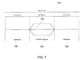
- the CDCF signal 702 is sent inside an IPP field 700.
- the IPP field 700 may be divided into time reserved for the CDCF signal 704 and some time margins at left 706 and right 708 to allow for imperfect synchronization, imperfect zero crossing detection, load-induce phase shifts of the mains signal, etc.
- a system may listen to the CDCF signal during the entire IPP field 700 in order to detect it. Generally, the transmitter of the CDCF tries to send it in the middle of the IPP field 700.
- the time unit employed for the schedule of the channel access is the TDMU (Time Domain Multiplexing Unit).
- TDMU Time Domain Multiplexing Unit
- the TDMU 800 is divided in eight TDMSs 802, 804, 806, 808, 810, 812,814, 816 and each slot is assigned for the exclusive use of all the devices of a specific system category present on the channel. If two adjacent TDMSs (for example TMDS #5 810 and TDMS #6 812) are assigned to different system categories, then a silence margin may be placed across the TDMS boundary 818.
- the TDMS silence margin is twice the duration of the CDCF margin (706, 708 FIG. 7 ) and is centered on the TDMS boundary.
- each TDMS depends on the network status.
- the network status sensed by a device may be different from the network status sensed by another device, even if the two devices belong to the same system category. This property of the network status allows some form of time-slot re-use to increase overall network throughput.
- TDMS allocation may be implemented within the scope of this disclosure, for example as discussed above, one policy may allocate at least 50% of the available resources to the Access system categories and the in-home system categories receive the remaining resources. Policies should take into consideration certain design constraints.
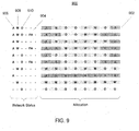
- the general procedure for TDMS allocation is to start allocating TDMS for the case of a full network status (for example, for a network including A, W, 0 system categories each of which allocation is described as A, W and O respectively in Figure 9 and Figure 10 ), and then create the other allocations by assigning the TDMS of the absent system to the present systems.
- TDMS to System Categories, it may be taken into consideration that there is trade-off between latency and throughput efficiency.
- Latency is proportional to the distance between TDMSs assigned to the same BPL System Category.
- Throughput efficiency is proportional to the number of TDMSs assigned consecutively to the same BPL System Category since a TDMS silence margin equal to twice the CDCF margin is centered on the TDMS boundary.
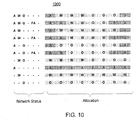
- FIGS. 9 and 10 show two examples of such trade-offs.
- a possible network status is shown on the left and the corresponding allocations for System Categories is shown on the right.
- the labels "A” 906, “W” 908 and “O” 910 are used to indicate Access, Wavelet and OFDM System Categories, respectively, being detected in as part of the network status.
- the label "FA” 904 in the network status signifies that the Access System Category is requesting Full bandwidth.
- a Mother Allocation table 900 is shown in FIG. 9 .
- the first row 902 privileges latency at the expense of throughput efficiency by interleaving A, W and O allocations. Since W and O system categories get two discontinuous allocations, efficiency is lower. However, this interleaving also reduces the maximum separation between two W (or two O) allocations, thus reducing latency.
- a second Mother Allocation table 1000 is shown.
- the first row has the same number of slots allocated to the respective System Categories as the previous example but it allows better throughput efficiency by providing single contiguous allocations for A, W and O systems. However, this arrangement increases the latency (e.g., the maximum time between consecutive W allocations is longer).
- the selected policy should take into account the above mentioned trade-offs.
- a subset of devices in a given system may not receive signals from one or more of the systems represented in the Mother Allocation.
- two of the O devices may not hear any signals corresponding to the A system category.
- the two devices may decide (or make a request) to use the time slots that would otherwise have been allocated to the A system category.
- the devices may first need permission from a centralized master device to be allocated the time slots.
- the devices may decide that the chance for interference is minimal and the time slots can still be used.
- exemplary Commonly Distributed Coordination Function (CDCF) signals have the following characteristics:
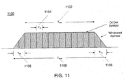
- the CDCF signal 1100 may be defined by the following parameters: An IFFT interval 1104, which may include 512 times samples over 5.12 microsections. An ODFM symbol duration 1102, which may include 6144 time samples over 61.44 microseconds. A windowing duration 1106 which may include 1024 time samples over 10.24 microseconds. And a CDCF signal interval 1108 which may include 8192 sampels over 81.92 microsections.
- Carriers that are always masked in order to meet the Transmit Spectrum Mask inside the range from 2 to 30 MHz are shaded. Additional carriers may be masked by the equipments depending on local regulations.
- the CDCF signals use carriers from 11 to 153 as maximum (they can use a bit less to comply with additional regulation requirements).
- the IPP protocol establishes the use of four different sets of phases for CDCF signals based on the previously defined OFDM symbol using different phases at each carrier.
- each phase vector is shown in the tables on FIG. 12 .
- "Start No.” in the table shows how the original phase vector shown in the reference table is shifted for the corresponding phase vector. Namely, if the "Start No.” is m, the phase of i-th sub-carrier is equal to the phase reference whose carrier index is (i+m) mod 256.
- Phase Vector Start No. PAR (dB) Use Phase 1 1 7.61 IPP Protocol: access Phase 2 2 7.97 IPP Protocol: Wavelet Phase 3 14 7.47 IPP Protocol: OFDM Phase 4 42 7.43 IPP Protocol: re-sync or access Phase 5 47 7.70 Coexistence Protocol Phase 6 58 7.45 Coexistence Protocol
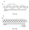
- a sync point 1300 may be defined by the zero crossing offset of the AC line current. For example at 0 degrees., 60 degrees, 120 degrees, 180 degrees, 240 degrees, and/or 300 degrees relative to a zero-cross point 1302 of the AC main.
- Sync Points for single-phase AC mains and three-phase AC mains are shown in FIG. 13A and FIG. 13B , respectively.
- the first IPP field begins at IPP_OFFSET time after a Sync Point.
- the accuracy of the zero cross detection circuit, noise on powerline and ambient temperature are some of the factors that affect the accuracy with which a device can determine the Sync Points. Thus, Sync Points observed by different device can be offset from each other.
- a start-up procedure may be utilized when a new device joins a system and when global start-up is required, for example, after a power outage.
- the start-up procedure assures that the new device is able to detect the presence of other networks already transmitting CDCF signals, and to coordinate with the existing networks.
- the Access system category is likely to span a relatively large geographic area and thus may occupy the same medium with any number of in-home systems.
- the access station(s) may follow the start up procedure defined for access networks and may search for CDCF signal from other systems for a start up duration, for example, at every sync point for one to three complete round robin cycles at every possible sync point (in some embodiments every 60 degrees of the AC lines cycle).
- a status indicator message to the HE notifying the presence and status of any in-home systems.
- the HE may send an IPP mode indicator message to the new device indicating the mode of the access network and timing of the IPP signal which it may begin transmitting in the IPP access fields.
- a resynchronization signal may be transmitted in the resynch field of the out of sync in-home systems, as explained below.
- the new access devices may be restricted to transmission and reception of management messages for joining the access network and IPP management until the procedure is complete, including resynchronization of any out of sync in-home networks.
- Access system categories should have the possibility of initiating a global re-synch (similar to a global start-up after power outage).
- the in-home devices may follow the start up procedure defined for in-home system categories and may search for CDCF signals from other system categories for IPP_STARTUP_TIME duration at every Sync Point.
- the IPP_STARTUP_TIME duration Once an in-home device successfully joins an in-home system category and the IPP_STARTUP_TIME duration has expired, it may send a CC_IPP.IND message to the manager notifying the presence and status of any access and/or in-home systems.
- the new device may follow any instructions indicated in the IPP Beacon ENTRY (BENTRY) message contained in period Beacon transmissions made by the master.
- BENTRY IPP Beacon ENTRY
- the manager may execute the resync procedure described below to become synchronized with the Access system category. If the manager detects the presence of an out of sync in-home system category directly or from receiving a CC_IPP.IND message, it may also execute the resync.
- the new in-home devices may be restricted to transmission and reception of management messages for joining the in-home network and IPP management until the procedure describe herein is complete, including resynchronization of any out of sync in-home networks.
- the start-up sequence of systems after a global power outage follows the same order which defines how the IPP windows are assigned to the different system categories (for example, in a BPL system: A, W, O). If access is deployed in area, the Access system category is the first to start up then followed by the In-Home systems. This may be accomplished by a back-off procedure.
- an Access system category device starts signaling in the IPP Window as soon as it is ready.
- W and O system category devices choose a number N (for example, a number between 5 and 10) and wait N allocation periods to start signaling in the IPP Window.
- the system may listen to the channel to detect other possible CDCF signals.
- every system waits three Allocation Periods sending CDCF signals and listening at every Sync Point for other CDCF signals. Once the network status is determined the system may start to use the channel for communication purposes.
- all devices in a system monitor every sync point whenever the device is not actively transmitting or receiving in order to detect the presence of other systems that may not be synchronized with the system the device belong.
- an Access system category cannot be resynchrnoized.
- an in-home network that is synchronized with an access network may not resynchronize and may ignore any resync signal transmitted in it's resync field. Resynchronization is handled by master nodes. Below are two examples of two resynchonization procedures for a BPL system with Access system category and In Home Systems sharing the communication medium.
- a device on the communication medium may request a re-synchronization. For example, if an out of synchronization in-home system is detected by a device belonging to an Access system category, the device may immediately send an GE_IPP_STATUS.IND message to the HE notifying that an out of sync in-home network was detected.
- the access system category device that detected the out of sync in-home system category may transmits in the resync field of the in-home system a predetermined signal (for example a CDCF P3 signal if the in-home system is Wavelet or a CDCF P2 signal if the in-home system is OFDM for several consecutive IPP Periods, for example, for two to five cycles).
- a predetermined signal for example a CDCF P3 signal if the in-home system is Wavelet or a CDCF P2 signal if the in-home system is OFDM for several consecutive IPP Periods, for example, for two to five cycles.
- the access system category device may transmits the CDCF signals in the Access IPP Window as it was before to provide the reference to the in-home system to synchronize with.
- an in-home device that detects a CDCF resync signal (for example, P3 if Wavelet or P2 if OFDM) in the resync field of his IPP Window may sends a CC_IPP.IND message to the master indicating a resync signal was detected.
- the master receiving a CC_IPP.IND message for an in-home network that is not synchronized with an Access system category will update the information in the Central Beacon to stop all IPP signal and data transmissions in the network and will several IPP periods, for example, five period. After the IPP periods, the master will synchronize to an Access system category if detected, or to a detected in-home system that is different from the synchronization before resync was detected and resume network operation as appropriate for the detected network status.
- the in-home system may ignore the re-sync request.
- an In-Home system category detects the presence of one or more unsynchronized In-Home system categories and detects that an Access system category is present, then:
- an In-Home system category detects the presence of one or more unsynchronized In Home system categories or devices and does not detect any Access system category present, then:
- all slaves inform the master about the network status they have detected.
- the slaves may confer the network status information at start-up, after a re-synch, and whenever network status changes.
- the master maintains list of the network status associated with all devices in his domain.
- the master advertises in the beacon the worst case network status, that is, the network status that is associated with the fewest TDMSs associated with its system.
- Any device can, optionally, initiate a CSMA link using the TDMSs corresponding to the network status advertised in the beacon without master intervention and without creating interference to neighboring systems whatever their network status is.
- a simple handshake between TX and RX allows communicating devices to discover if additional TDMSs are available for communication, for example, when they have a network status that is different from the one advertised in the beacon. These messages may be sent, for example, by piggybacking the ACK packet with networks status information, or by using management messages.
- a device requires establishing a TDMA link, master intervention is required. Since master maintains the list of network statuses associated with every device in its domain, the master can, optionally, inform TX and RX of their common TDMSs by computing the Usable Time Slot (UST).
- UST Usable Time Slot
- an Access system category can switch to FDM mode only if no neighboring In-Home devices are sensed, or if the network status indicates the presence of only In-Home system categories that can support FDM mode (for example, W system categories NOT transmitting P2-P4 and O system categories NOT transmitting P3-P4). If an Access system category wants to initiate FDM mode, appropriate IPP signals are transmitted in Access IPP windows. If neighboring In-Home devices are present and cannot support FDM, they will transmit P4 in the second IPP field. As an alternative, if the In-Home devices that do not support FDM are not sending data they can stop transmitting their IPP in the first field and, as a consequence, change the network status sensed by access devices. If neighboring In-Home devices can support FDM, they can continue to transmit their IPP signal in the first IPP field and switch all data communications in the appropriate higher bandwith.
- Access devices do not sense an IH IPP, they can start transmitting in FDM mode. However, if network status changes and neighboring IH with no FDM capability devices appear, for example, transmitting a P4 in the second IPP field, the access devices reverts to TDM mode.
- An FDM Access system category may indicate its mode and granularity (FDM partial or FDM full) in the appropriate CDCF Fields continuously in its corresponding IPP Window.
- An FDM Access system category may monitor first and second Fields in the IPP Wavelet and IPP OFDM windows in order to detect the presence of P1901 Wavelet and P1901 OFDM systems and to detect their FDM capability ("FDM capable” or “not FDM capable”).
- An FDM Access system category may detect the FDM capability of a In-Home device within a number of seconds of the In-Home device beginning to indicate its presence by transmitting in the appropriate IPP window (for example, in 5 seconds or less).
- the In-Home device may enter FDM mode and the Access system category may continue to monitor for signals in the IPP Wavelet and IPP FFT windows.
- the In-home device indicates that it does not support FDM mode (for example, by signaling the Phase P4 signal in second field of the appropriate IPP Window) then:
- Access system category may send the CDCF signal occupying only the frequencies corresponding to its FDM band.
- In-Home systems may send the CDCF signal limited to the frequencies corresponding to their FDM band too (e.g., by masking a subset of the carriers). This avoids interferences from one band onto the other because the Access system category in FDM could not signal with the same periodicity that the In-Home systems, (for example, within the same T ipp .)
- system categories may optionally perform power control on data communications and on CDCF.
- Devices may avoid transmitting continuously the CDCF together with all other devices in the network. Devices can make autonomous decision based on network status. If network status contains only one system category, then the device can stop temporarily transmitting the CDCF (for example, transmitting 1 CDCF every TBD IPP Periods) while still continuously scanning for unsynchronized systems or for a new network status. Devices can also transmit a p-persistent CDCF, for example, transmit the CDCF signal with probability p.
- the device generally resumes sending the CDCF.
Landscapes
- Engineering & Computer Science (AREA)
- Computer Networks & Wireless Communication (AREA)
- Signal Processing (AREA)
- Power Engineering (AREA)
- Mobile Radio Communication Systems (AREA)
- Cable Transmission Systems, Equalization Of Radio And Reduction Of Echo (AREA)
Applications Claiming Priority (2)
| Application Number | Priority Date | Filing Date | Title |
|---|---|---|---|
| US7302408P | 2008-06-16 | 2008-06-16 | |
| PCT/US2009/047530 WO2010005733A1 (en) | 2008-06-16 | 2009-06-16 | Managing coexistence among signaling protocols on a shared medium |
Publications (3)
| Publication Number | Publication Date |
|---|---|
| EP2294721A1 EP2294721A1 (en) | 2011-03-16 |
| EP2294721A4 EP2294721A4 (en) | 2014-07-02 |
| EP2294721B1 true EP2294721B1 (en) | 2016-11-16 |
Family
ID=41507369
Family Applications (1)
| Application Number | Title | Priority Date | Filing Date |
|---|---|---|---|
| EP09794925.9A Active EP2294721B1 (en) | 2008-06-16 | 2009-06-16 | Managing coexistence among signaling protocols on a shared medium |
Country Status (5)
| Country | Link |
|---|---|
| US (2) | US8295301B2 (es) |
| EP (1) | EP2294721B1 (es) |
| JP (1) | JP2011524724A (es) |
| ES (1) | ES2616501T3 (es) |
| WO (1) | WO2010005733A1 (es) |
Families Citing this family (178)
| Publication number | Priority date | Publication date | Assignee | Title |
|---|---|---|---|---|
| US20080144544A1 (en) * | 2006-12-19 | 2008-06-19 | Sam Shi | Method and system of combining signals in bpl communications |
| WO2011034753A2 (en) | 2009-09-18 | 2011-03-24 | Marvell World Trade Ltd. | Short packet for use in beamforming |
| CN102948119B (zh) | 2010-04-12 | 2016-04-20 | 高通股份有限公司 | 提供用于在网络中进行低开销通信的定界符 |
| US9032075B2 (en) * | 2011-10-12 | 2015-05-12 | President And Fellows Of Harvard College | Systems and methods for medium access control |
| US9231658B2 (en) | 2012-06-20 | 2016-01-05 | Texas Instruments Incorporated | Coexistence primitives in power line communication networks |
| US10009065B2 (en) | 2012-12-05 | 2018-06-26 | At&T Intellectual Property I, L.P. | Backhaul link for distributed antenna system |
| US9113347B2 (en) | 2012-12-05 | 2015-08-18 | At&T Intellectual Property I, Lp | Backhaul link for distributed antenna system |
| US9025527B2 (en) | 2012-12-13 | 2015-05-05 | Qualcomm Incorporated | Adaptive channel reuse mechanism in communication networks |
| US20140219369A1 (en) * | 2013-02-07 | 2014-08-07 | Flextronics Ap, Llc | Power line communications signal aggregation and switch |
| EP2979370B1 (en) | 2013-03-28 | 2022-02-09 | Sony Group Corporation | Communication device and method providing beamforming for two or more transmission channels |
| US9999038B2 (en) | 2013-05-31 | 2018-06-12 | At&T Intellectual Property I, L.P. | Remote distributed antenna system |
| US9525524B2 (en) | 2013-05-31 | 2016-12-20 | At&T Intellectual Property I, L.P. | Remote distributed antenna system |
| US8897697B1 (en) | 2013-11-06 | 2014-11-25 | At&T Intellectual Property I, Lp | Millimeter-wave surface-wave communications |
| US9209902B2 (en) | 2013-12-10 | 2015-12-08 | At&T Intellectual Property I, L.P. | Quasi-optical coupler |
| US9236909B2 (en) | 2013-12-19 | 2016-01-12 | Stmicroelectronics, Inc. | Zero standby power for powerline communication devices |
| US9692101B2 (en) | 2014-08-26 | 2017-06-27 | At&T Intellectual Property I, L.P. | Guided wave couplers for coupling electromagnetic waves between a waveguide surface and a surface of a wire |
| US9768833B2 (en) | 2014-09-15 | 2017-09-19 | At&T Intellectual Property I, L.P. | Method and apparatus for sensing a condition in a transmission medium of electromagnetic waves |
| US10063280B2 (en) | 2014-09-17 | 2018-08-28 | At&T Intellectual Property I, L.P. | Monitoring and mitigating conditions in a communication network |
| US9628854B2 (en) | 2014-09-29 | 2017-04-18 | At&T Intellectual Property I, L.P. | Method and apparatus for distributing content in a communication network |
| US9615269B2 (en) | 2014-10-02 | 2017-04-04 | At&T Intellectual Property I, L.P. | Method and apparatus that provides fault tolerance in a communication network |
| US9685992B2 (en) | 2014-10-03 | 2017-06-20 | At&T Intellectual Property I, L.P. | Circuit panel network and methods thereof |
| US9503189B2 (en) | 2014-10-10 | 2016-11-22 | At&T Intellectual Property I, L.P. | Method and apparatus for arranging communication sessions in a communication system |
| US9973299B2 (en) | 2014-10-14 | 2018-05-15 | At&T Intellectual Property I, L.P. | Method and apparatus for adjusting a mode of communication in a communication network |
| US9762289B2 (en) | 2014-10-14 | 2017-09-12 | At&T Intellectual Property I, L.P. | Method and apparatus for transmitting or receiving signals in a transportation system |
| US9769020B2 (en) | 2014-10-21 | 2017-09-19 | At&T Intellectual Property I, L.P. | Method and apparatus for responding to events affecting communications in a communication network |
| US9653770B2 (en) | 2014-10-21 | 2017-05-16 | At&T Intellectual Property I, L.P. | Guided wave coupler, coupling module and methods for use therewith |
| US9627768B2 (en) | 2014-10-21 | 2017-04-18 | At&T Intellectual Property I, L.P. | Guided-wave transmission device with non-fundamental mode propagation and methods for use therewith |
| US9577306B2 (en) | 2014-10-21 | 2017-02-21 | At&T Intellectual Property I, L.P. | Guided-wave transmission device and methods for use therewith |
| US9564947B2 (en) | 2014-10-21 | 2017-02-07 | At&T Intellectual Property I, L.P. | Guided-wave transmission device with diversity and methods for use therewith |
| US9780834B2 (en) | 2014-10-21 | 2017-10-03 | At&T Intellectual Property I, L.P. | Method and apparatus for transmitting electromagnetic waves |
| US9312919B1 (en) | 2014-10-21 | 2016-04-12 | At&T Intellectual Property I, Lp | Transmission device with impairment compensation and methods for use therewith |
| US9520945B2 (en) | 2014-10-21 | 2016-12-13 | At&T Intellectual Property I, L.P. | Apparatus for providing communication services and methods thereof |
| US9954287B2 (en) | 2014-11-20 | 2018-04-24 | At&T Intellectual Property I, L.P. | Apparatus for converting wireless signals and electromagnetic waves and methods thereof |
| US10340573B2 (en) | 2016-10-26 | 2019-07-02 | At&T Intellectual Property I, L.P. | Launcher with cylindrical coupling device and methods for use therewith |
| US9680670B2 (en) | 2014-11-20 | 2017-06-13 | At&T Intellectual Property I, L.P. | Transmission device with channel equalization and control and methods for use therewith |
| US9997819B2 (en) | 2015-06-09 | 2018-06-12 | At&T Intellectual Property I, L.P. | Transmission medium and method for facilitating propagation of electromagnetic waves via a core |
| US9654173B2 (en) | 2014-11-20 | 2017-05-16 | At&T Intellectual Property I, L.P. | Apparatus for powering a communication device and methods thereof |
| US9544006B2 (en) | 2014-11-20 | 2017-01-10 | At&T Intellectual Property I, L.P. | Transmission device with mode division multiplexing and methods for use therewith |
| US9461706B1 (en) | 2015-07-31 | 2016-10-04 | At&T Intellectual Property I, Lp | Method and apparatus for exchanging communication signals |
| US9742462B2 (en) | 2014-12-04 | 2017-08-22 | At&T Intellectual Property I, L.P. | Transmission medium and communication interfaces and methods for use therewith |
| US10009067B2 (en) | 2014-12-04 | 2018-06-26 | At&T Intellectual Property I, L.P. | Method and apparatus for configuring a communication interface |
| US9800327B2 (en) | 2014-11-20 | 2017-10-24 | At&T Intellectual Property I, L.P. | Apparatus for controlling operations of a communication device and methods thereof |
| US10243784B2 (en) | 2014-11-20 | 2019-03-26 | At&T Intellectual Property I, L.P. | System for generating topology information and methods thereof |
| US9152737B1 (en) * | 2014-11-26 | 2015-10-06 | Sense Labs, Inc. | Providing notifications to a user |
| US10144036B2 (en) | 2015-01-30 | 2018-12-04 | At&T Intellectual Property I, L.P. | Method and apparatus for mitigating interference affecting a propagation of electromagnetic waves guided by a transmission medium |
| US9876570B2 (en) | 2015-02-20 | 2018-01-23 | At&T Intellectual Property I, Lp | Guided-wave transmission device with non-fundamental mode propagation and methods for use therewith |
| US9749013B2 (en) | 2015-03-17 | 2017-08-29 | At&T Intellectual Property I, L.P. | Method and apparatus for reducing attenuation of electromagnetic waves guided by a transmission medium |
| US9705561B2 (en) | 2015-04-24 | 2017-07-11 | At&T Intellectual Property I, L.P. | Directional coupling device and methods for use therewith |
| US10224981B2 (en) | 2015-04-24 | 2019-03-05 | At&T Intellectual Property I, Lp | Passive electrical coupling device and methods for use therewith |
| US9793954B2 (en) | 2015-04-28 | 2017-10-17 | At&T Intellectual Property I, L.P. | Magnetic coupling device and methods for use therewith |
| US9948354B2 (en) | 2015-04-28 | 2018-04-17 | At&T Intellectual Property I, L.P. | Magnetic coupling device with reflective plate and methods for use therewith |
| US9871282B2 (en) | 2015-05-14 | 2018-01-16 | At&T Intellectual Property I, L.P. | At least one transmission medium having a dielectric surface that is covered at least in part by a second dielectric |
| US9748626B2 (en) | 2015-05-14 | 2017-08-29 | At&T Intellectual Property I, L.P. | Plurality of cables having different cross-sectional shapes which are bundled together to form a transmission medium |
| US9490869B1 (en) | 2015-05-14 | 2016-11-08 | At&T Intellectual Property I, L.P. | Transmission medium having multiple cores and methods for use therewith |
| US10679767B2 (en) | 2015-05-15 | 2020-06-09 | At&T Intellectual Property I, L.P. | Transmission medium having a conductive material and methods for use therewith |
| US10650940B2 (en) | 2015-05-15 | 2020-05-12 | At&T Intellectual Property I, L.P. | Transmission medium having a conductive material and methods for use therewith |
| US9917341B2 (en) | 2015-05-27 | 2018-03-13 | At&T Intellectual Property I, L.P. | Apparatus and method for launching electromagnetic waves and for modifying radial dimensions of the propagating electromagnetic waves |
| US10103801B2 (en) | 2015-06-03 | 2018-10-16 | At&T Intellectual Property I, L.P. | Host node device and methods for use therewith |
| US9912381B2 (en) | 2015-06-03 | 2018-03-06 | At&T Intellectual Property I, Lp | Network termination and methods for use therewith |
| US9866309B2 (en) | 2015-06-03 | 2018-01-09 | At&T Intellectual Property I, Lp | Host node device and methods for use therewith |
| US10812174B2 (en) | 2015-06-03 | 2020-10-20 | At&T Intellectual Property I, L.P. | Client node device and methods for use therewith |
| US10348391B2 (en) | 2015-06-03 | 2019-07-09 | At&T Intellectual Property I, L.P. | Client node device with frequency conversion and methods for use therewith |
| US10154493B2 (en) | 2015-06-03 | 2018-12-11 | At&T Intellectual Property I, L.P. | Network termination and methods for use therewith |
| US9913139B2 (en) | 2015-06-09 | 2018-03-06 | At&T Intellectual Property I, L.P. | Signal fingerprinting for authentication of communicating devices |
| US10142086B2 (en) | 2015-06-11 | 2018-11-27 | At&T Intellectual Property I, L.P. | Repeater and methods for use therewith |
| US9608692B2 (en) | 2015-06-11 | 2017-03-28 | At&T Intellectual Property I, L.P. | Repeater and methods for use therewith |
| US9820146B2 (en) | 2015-06-12 | 2017-11-14 | At&T Intellectual Property I, L.P. | Method and apparatus for authentication and identity management of communicating devices |
| US9667317B2 (en) | 2015-06-15 | 2017-05-30 | At&T Intellectual Property I, L.P. | Method and apparatus for providing security using network traffic adjustments |
| US9865911B2 (en) | 2015-06-25 | 2018-01-09 | At&T Intellectual Property I, L.P. | Waveguide system for slot radiating first electromagnetic waves that are combined into a non-fundamental wave mode second electromagnetic wave on a transmission medium |
| US9640850B2 (en) | 2015-06-25 | 2017-05-02 | At&T Intellectual Property I, L.P. | Methods and apparatus for inducing a non-fundamental wave mode on a transmission medium |
| US9509415B1 (en) | 2015-06-25 | 2016-11-29 | At&T Intellectual Property I, L.P. | Methods and apparatus for inducing a fundamental wave mode on a transmission medium |
| US10341142B2 (en) | 2015-07-14 | 2019-07-02 | At&T Intellectual Property I, L.P. | Apparatus and methods for generating non-interfering electromagnetic waves on an uninsulated conductor |
| US9836957B2 (en) | 2015-07-14 | 2017-12-05 | At&T Intellectual Property I, L.P. | Method and apparatus for communicating with premises equipment |
| US10033108B2 (en) | 2015-07-14 | 2018-07-24 | At&T Intellectual Property I, L.P. | Apparatus and methods for generating an electromagnetic wave having a wave mode that mitigates interference |
| US10320586B2 (en) | 2015-07-14 | 2019-06-11 | At&T Intellectual Property I, L.P. | Apparatus and methods for generating non-interfering electromagnetic waves on an insulated transmission medium |
| US10044409B2 (en) | 2015-07-14 | 2018-08-07 | At&T Intellectual Property I, L.P. | Transmission medium and methods for use therewith |
| US9882257B2 (en) | 2015-07-14 | 2018-01-30 | At&T Intellectual Property I, L.P. | Method and apparatus for launching a wave mode that mitigates interference |
| US10033107B2 (en) | 2015-07-14 | 2018-07-24 | At&T Intellectual Property I, L.P. | Method and apparatus for coupling an antenna to a device |
| US10170840B2 (en) | 2015-07-14 | 2019-01-01 | At&T Intellectual Property I, L.P. | Apparatus and methods for sending or receiving electromagnetic signals |
| US9628116B2 (en) | 2015-07-14 | 2017-04-18 | At&T Intellectual Property I, L.P. | Apparatus and methods for transmitting wireless signals |
| US10148016B2 (en) | 2015-07-14 | 2018-12-04 | At&T Intellectual Property I, L.P. | Apparatus and methods for communicating utilizing an antenna array |
| US10205655B2 (en) | 2015-07-14 | 2019-02-12 | At&T Intellectual Property I, L.P. | Apparatus and methods for communicating utilizing an antenna array and multiple communication paths |
| US9853342B2 (en) | 2015-07-14 | 2017-12-26 | At&T Intellectual Property I, L.P. | Dielectric transmission medium connector and methods for use therewith |
| US9722318B2 (en) | 2015-07-14 | 2017-08-01 | At&T Intellectual Property I, L.P. | Method and apparatus for coupling an antenna to a device |
| US9847566B2 (en) | 2015-07-14 | 2017-12-19 | At&T Intellectual Property I, L.P. | Method and apparatus for adjusting a field of a signal to mitigate interference |
| US9608740B2 (en) | 2015-07-15 | 2017-03-28 | At&T Intellectual Property I, L.P. | Method and apparatus for launching a wave mode that mitigates interference |
| US10090606B2 (en) | 2015-07-15 | 2018-10-02 | At&T Intellectual Property I, L.P. | Antenna system with dielectric array and methods for use therewith |
| US9793951B2 (en) | 2015-07-15 | 2017-10-17 | At&T Intellectual Property I, L.P. | Method and apparatus for launching a wave mode that mitigates interference |
| US10784670B2 (en) | 2015-07-23 | 2020-09-22 | At&T Intellectual Property I, L.P. | Antenna support for aligning an antenna |
| US9948333B2 (en) | 2015-07-23 | 2018-04-17 | At&T Intellectual Property I, L.P. | Method and apparatus for wireless communications to mitigate interference |
| US9871283B2 (en) | 2015-07-23 | 2018-01-16 | At&T Intellectual Property I, Lp | Transmission medium having a dielectric core comprised of plural members connected by a ball and socket configuration |
| US9749053B2 (en) | 2015-07-23 | 2017-08-29 | At&T Intellectual Property I, L.P. | Node device, repeater and methods for use therewith |
| US9912027B2 (en) | 2015-07-23 | 2018-03-06 | At&T Intellectual Property I, L.P. | Method and apparatus for exchanging communication signals |
| US9735833B2 (en) | 2015-07-31 | 2017-08-15 | At&T Intellectual Property I, L.P. | Method and apparatus for communications management in a neighborhood network |
| US10020587B2 (en) | 2015-07-31 | 2018-07-10 | At&T Intellectual Property I, L.P. | Radial antenna and methods for use therewith |
| US9967173B2 (en) | 2015-07-31 | 2018-05-08 | At&T Intellectual Property I, L.P. | Method and apparatus for authentication and identity management of communicating devices |
| US9904535B2 (en) | 2015-09-14 | 2018-02-27 | At&T Intellectual Property I, L.P. | Method and apparatus for distributing software |
| US9705571B2 (en) | 2015-09-16 | 2017-07-11 | At&T Intellectual Property I, L.P. | Method and apparatus for use with a radio distributed antenna system |
| US10009063B2 (en) | 2015-09-16 | 2018-06-26 | At&T Intellectual Property I, L.P. | Method and apparatus for use with a radio distributed antenna system having an out-of-band reference signal |
| US10009901B2 (en) | 2015-09-16 | 2018-06-26 | At&T Intellectual Property I, L.P. | Method, apparatus, and computer-readable storage medium for managing utilization of wireless resources between base stations |
| US10079661B2 (en) | 2015-09-16 | 2018-09-18 | At&T Intellectual Property I, L.P. | Method and apparatus for use with a radio distributed antenna system having a clock reference |
| US10051629B2 (en) | 2015-09-16 | 2018-08-14 | At&T Intellectual Property I, L.P. | Method and apparatus for use with a radio distributed antenna system having an in-band reference signal |
| US10136434B2 (en) | 2015-09-16 | 2018-11-20 | At&T Intellectual Property I, L.P. | Method and apparatus for use with a radio distributed antenna system having an ultra-wideband control channel |
| US9769128B2 (en) | 2015-09-28 | 2017-09-19 | At&T Intellectual Property I, L.P. | Method and apparatus for encryption of communications over a network |
| US9729197B2 (en) | 2015-10-01 | 2017-08-08 | At&T Intellectual Property I, L.P. | Method and apparatus for communicating network management traffic over a network |
| US10074890B2 (en) | 2015-10-02 | 2018-09-11 | At&T Intellectual Property I, L.P. | Communication device and antenna with integrated light assembly |
| US9882277B2 (en) | 2015-10-02 | 2018-01-30 | At&T Intellectual Property I, Lp | Communication device and antenna assembly with actuated gimbal mount |
| US9876264B2 (en) | 2015-10-02 | 2018-01-23 | At&T Intellectual Property I, Lp | Communication system, guided wave switch and methods for use therewith |
| US10665942B2 (en) | 2015-10-16 | 2020-05-26 | At&T Intellectual Property I, L.P. | Method and apparatus for adjusting wireless communications |
| US10355367B2 (en) | 2015-10-16 | 2019-07-16 | At&T Intellectual Property I, L.P. | Antenna structure for exchanging wireless signals |
| US10051483B2 (en) | 2015-10-16 | 2018-08-14 | At&T Intellectual Property I, L.P. | Method and apparatus for directing wireless signals |
| FR3051612B1 (fr) * | 2016-05-17 | 2018-05-11 | Centre National D'etudes Spatiales (Cnes) | Procede et systeme de telecommunication |
| US10375718B2 (en) * | 2016-08-11 | 2019-08-06 | Qualcomm Incorporated | Adaptive resource management for robust communication in new radio |
| US9912419B1 (en) | 2016-08-24 | 2018-03-06 | At&T Intellectual Property I, L.P. | Method and apparatus for managing a fault in a distributed antenna system |
| US9860075B1 (en) | 2016-08-26 | 2018-01-02 | At&T Intellectual Property I, L.P. | Method and communication node for broadband distribution |
| US10291311B2 (en) | 2016-09-09 | 2019-05-14 | At&T Intellectual Property I, L.P. | Method and apparatus for mitigating a fault in a distributed antenna system |
| US11032819B2 (en) | 2016-09-15 | 2021-06-08 | At&T Intellectual Property I, L.P. | Method and apparatus for use with a radio distributed antenna system having a control channel reference signal |
| US10340600B2 (en) | 2016-10-18 | 2019-07-02 | At&T Intellectual Property I, L.P. | Apparatus and methods for launching guided waves via plural waveguide systems |
| US10135147B2 (en) | 2016-10-18 | 2018-11-20 | At&T Intellectual Property I, L.P. | Apparatus and methods for launching guided waves via an antenna |
| US10135146B2 (en) | 2016-10-18 | 2018-11-20 | At&T Intellectual Property I, L.P. | Apparatus and methods for launching guided waves via circuits |
| US9876605B1 (en) | 2016-10-21 | 2018-01-23 | At&T Intellectual Property I, L.P. | Launcher and coupling system to support desired guided wave mode |
| US10374316B2 (en) | 2016-10-21 | 2019-08-06 | At&T Intellectual Property I, L.P. | System and dielectric antenna with non-uniform dielectric |
| US10811767B2 (en) | 2016-10-21 | 2020-10-20 | At&T Intellectual Property I, L.P. | System and dielectric antenna with convex dielectric radome |
| US9991580B2 (en) | 2016-10-21 | 2018-06-05 | At&T Intellectual Property I, L.P. | Launcher and coupling system for guided wave mode cancellation |
| US10312567B2 (en) | 2016-10-26 | 2019-06-04 | At&T Intellectual Property I, L.P. | Launcher with planar strip antenna and methods for use therewith |
| US10225025B2 (en) | 2016-11-03 | 2019-03-05 | At&T Intellectual Property I, L.P. | Method and apparatus for detecting a fault in a communication system |
| US10224634B2 (en) | 2016-11-03 | 2019-03-05 | At&T Intellectual Property I, L.P. | Methods and apparatus for adjusting an operational characteristic of an antenna |
| US10291334B2 (en) | 2016-11-03 | 2019-05-14 | At&T Intellectual Property I, L.P. | System for detecting a fault in a communication system |
| US10498044B2 (en) | 2016-11-03 | 2019-12-03 | At&T Intellectual Property I, L.P. | Apparatus for configuring a surface of an antenna |
| US10535928B2 (en) | 2016-11-23 | 2020-01-14 | At&T Intellectual Property I, L.P. | Antenna system and methods for use therewith |
| US10090594B2 (en) | 2016-11-23 | 2018-10-02 | At&T Intellectual Property I, L.P. | Antenna system having structural configurations for assembly |
| US10340603B2 (en) | 2016-11-23 | 2019-07-02 | At&T Intellectual Property I, L.P. | Antenna system having shielded structural configurations for assembly |
| US10178445B2 (en) | 2016-11-23 | 2019-01-08 | At&T Intellectual Property I, L.P. | Methods, devices, and systems for load balancing between a plurality of waveguides |
| US10340601B2 (en) | 2016-11-23 | 2019-07-02 | At&T Intellectual Property I, L.P. | Multi-antenna system and methods for use therewith |
| US10361489B2 (en) | 2016-12-01 | 2019-07-23 | At&T Intellectual Property I, L.P. | Dielectric dish antenna system and methods for use therewith |
| US10305190B2 (en) | 2016-12-01 | 2019-05-28 | At&T Intellectual Property I, L.P. | Reflecting dielectric antenna system and methods for use therewith |
| US9927517B1 (en) | 2016-12-06 | 2018-03-27 | At&T Intellectual Property I, L.P. | Apparatus and methods for sensing rainfall |
| US10439675B2 (en) | 2016-12-06 | 2019-10-08 | At&T Intellectual Property I, L.P. | Method and apparatus for repeating guided wave communication signals |
| US10382976B2 (en) | 2016-12-06 | 2019-08-13 | At&T Intellectual Property I, L.P. | Method and apparatus for managing wireless communications based on communication paths and network device positions |
| US10135145B2 (en) | 2016-12-06 | 2018-11-20 | At&T Intellectual Property I, L.P. | Apparatus and methods for generating an electromagnetic wave along a transmission medium |
| US10637149B2 (en) | 2016-12-06 | 2020-04-28 | At&T Intellectual Property I, L.P. | Injection molded dielectric antenna and methods for use therewith |
| US10819035B2 (en) | 2016-12-06 | 2020-10-27 | At&T Intellectual Property I, L.P. | Launcher with helical antenna and methods for use therewith |
| US10755542B2 (en) | 2016-12-06 | 2020-08-25 | At&T Intellectual Property I, L.P. | Method and apparatus for surveillance via guided wave communication |
| US10020844B2 (en) | 2016-12-06 | 2018-07-10 | T&T Intellectual Property I, L.P. | Method and apparatus for broadcast communication via guided waves |
| US10727599B2 (en) | 2016-12-06 | 2020-07-28 | At&T Intellectual Property I, L.P. | Launcher with slot antenna and methods for use therewith |
| US10694379B2 (en) | 2016-12-06 | 2020-06-23 | At&T Intellectual Property I, L.P. | Waveguide system with device-based authentication and methods for use therewith |
| US10326494B2 (en) | 2016-12-06 | 2019-06-18 | At&T Intellectual Property I, L.P. | Apparatus for measurement de-embedding and methods for use therewith |
| US10359749B2 (en) | 2016-12-07 | 2019-07-23 | At&T Intellectual Property I, L.P. | Method and apparatus for utilities management via guided wave communication |
| US10243270B2 (en) | 2016-12-07 | 2019-03-26 | At&T Intellectual Property I, L.P. | Beam adaptive multi-feed dielectric antenna system and methods for use therewith |
| US10168695B2 (en) | 2016-12-07 | 2019-01-01 | At&T Intellectual Property I, L.P. | Method and apparatus for controlling an unmanned aircraft |
| US9893795B1 (en) | 2016-12-07 | 2018-02-13 | At&T Intellectual Property I, Lp | Method and repeater for broadband distribution |
| US10139820B2 (en) | 2016-12-07 | 2018-11-27 | At&T Intellectual Property I, L.P. | Method and apparatus for deploying equipment of a communication system |
| US10027397B2 (en) | 2016-12-07 | 2018-07-17 | At&T Intellectual Property I, L.P. | Distributed antenna system and methods for use therewith |
| US10547348B2 (en) | 2016-12-07 | 2020-01-28 | At&T Intellectual Property I, L.P. | Method and apparatus for switching transmission mediums in a communication system |
| US10446936B2 (en) | 2016-12-07 | 2019-10-15 | At&T Intellectual Property I, L.P. | Multi-feed dielectric antenna system and methods for use therewith |
| US10389029B2 (en) | 2016-12-07 | 2019-08-20 | At&T Intellectual Property I, L.P. | Multi-feed dielectric antenna system with core selection and methods for use therewith |
| US10411356B2 (en) | 2016-12-08 | 2019-09-10 | At&T Intellectual Property I, L.P. | Apparatus and methods for selectively targeting communication devices with an antenna array |
| US10389037B2 (en) | 2016-12-08 | 2019-08-20 | At&T Intellectual Property I, L.P. | Apparatus and methods for selecting sections of an antenna array and use therewith |
| US10938108B2 (en) | 2016-12-08 | 2021-03-02 | At&T Intellectual Property I, L.P. | Frequency selective multi-feed dielectric antenna system and methods for use therewith |
| US9911020B1 (en) | 2016-12-08 | 2018-03-06 | At&T Intellectual Property I, L.P. | Method and apparatus for tracking via a radio frequency identification device |
| US10069535B2 (en) | 2016-12-08 | 2018-09-04 | At&T Intellectual Property I, L.P. | Apparatus and methods for launching electromagnetic waves having a certain electric field structure |
| US10103422B2 (en) | 2016-12-08 | 2018-10-16 | At&T Intellectual Property I, L.P. | Method and apparatus for mounting network devices |
| US10601494B2 (en) | 2016-12-08 | 2020-03-24 | At&T Intellectual Property I, L.P. | Dual-band communication device and method for use therewith |
| US10916969B2 (en) | 2016-12-08 | 2021-02-09 | At&T Intellectual Property I, L.P. | Method and apparatus for providing power using an inductive coupling |
| US10326689B2 (en) | 2016-12-08 | 2019-06-18 | At&T Intellectual Property I, L.P. | Method and system for providing alternative communication paths |
| US10530505B2 (en) | 2016-12-08 | 2020-01-07 | At&T Intellectual Property I, L.P. | Apparatus and methods for launching electromagnetic waves along a transmission medium |
| US9998870B1 (en) | 2016-12-08 | 2018-06-12 | At&T Intellectual Property I, L.P. | Method and apparatus for proximity sensing |
| US10777873B2 (en) | 2016-12-08 | 2020-09-15 | At&T Intellectual Property I, L.P. | Method and apparatus for mounting network devices |
| US10340983B2 (en) | 2016-12-09 | 2019-07-02 | At&T Intellectual Property I, L.P. | Method and apparatus for surveying remote sites via guided wave communications |
| US9838896B1 (en) | 2016-12-09 | 2017-12-05 | At&T Intellectual Property I, L.P. | Method and apparatus for assessing network coverage |
| US10264586B2 (en) | 2016-12-09 | 2019-04-16 | At&T Mobility Ii Llc | Cloud-based packet controller and methods for use therewith |
| US10750252B2 (en) | 2017-02-22 | 2020-08-18 | Sense Labs, Inc. | Identifying device state changes using power data and network data |
| US9973940B1 (en) | 2017-02-27 | 2018-05-15 | At&T Intellectual Property I, L.P. | Apparatus and methods for dynamic impedance matching of a guided wave launcher |
| US10298293B2 (en) | 2017-03-13 | 2019-05-21 | At&T Intellectual Property I, L.P. | Apparatus of communication utilizing wireless network devices |
| KR20200081355A (ko) * | 2017-10-31 | 2020-07-07 | 가부시키가이샤 아데카 | 시트형 탈세포화 재료 및 동 재료를 사용하는 인공 혈관 |
| WO2020013422A1 (ko) * | 2018-07-13 | 2020-01-16 | 한국과학기술원 | 광대역저전력 통신을 위한 상호 공존 통신 방법 및 시스템 |
| US10586177B1 (en) | 2018-10-02 | 2020-03-10 | Sense Labs, Inc. | Training a mathematical model for a device using a smart plug |
| US11323153B2 (en) | 2019-07-29 | 2022-05-03 | Enphase Energy, Inc. | Protocol for multi-master communication coordination on shared media channel |
Citations (1)
| Publication number | Priority date | Publication date | Assignee | Title |
|---|---|---|---|---|
| US20070097960A1 (en) * | 2005-10-05 | 2007-05-03 | Akio Kurobe | Communication apparatus and coexistence method for enabling coexistence of communication systems |
Family Cites Families (25)
| Publication number | Priority date | Publication date | Assignee | Title |
|---|---|---|---|---|
| US4807248A (en) * | 1984-05-23 | 1989-02-21 | Rockwell International Corporation | Automatic resynchronization technique |
| US4689786A (en) * | 1985-03-21 | 1987-08-25 | Apple Computer, Inc. | Local area network with self assigned address method |
| US5732076A (en) * | 1995-10-26 | 1998-03-24 | Omnipoint Corporation | Coexisting communication systems |
| US6141355A (en) * | 1998-11-06 | 2000-10-31 | Path 1 Network Technologies, Inc. | Time-synchronized multi-layer network switch for providing quality of service guarantees in computer networks |
| US6917589B2 (en) * | 2001-01-25 | 2005-07-12 | Agere Systems Inc. | Automatic quality of service assignment in ethernet switches |
| US7583623B2 (en) * | 2001-03-02 | 2009-09-01 | Ofer Zimmerman | Method and system for packing management messages in a communication system |
| JP2002271355A (ja) * | 2001-03-13 | 2002-09-20 | Nec Corp | パケット通信システム及び識別子割付方法及び網側装置 |
| DE10140849B4 (de) * | 2001-08-21 | 2011-05-05 | Robert Bosch Gmbh | Elektronisches System mit einem Mehrfachzugriffsprotokoll und Verfahren für den Mehrfachzugriff |
| AU2003212813A1 (en) * | 2002-01-22 | 2003-09-02 | Xtremespectrum, Inc. | Method of managing time slots in a wireless network through the use of contention groups |
| KR20060021795A (ko) * | 2002-06-07 | 2006-03-08 | 엠버 코퍼레이션 | 경사도 라우팅을 사용하는 애드 혹 무선 네트워크 |
| KR100999094B1 (ko) * | 2003-06-27 | 2010-12-07 | 삼성전자주식회사 | 시분할 방식의 무선랜 통신방법 및 시스템 |
| WO2005008903A2 (en) * | 2003-07-03 | 2005-01-27 | Current Technologies, Llc | A power line communication system and method of operating the same |
| US8274961B2 (en) * | 2003-10-24 | 2012-09-25 | Sony Corporation | Apparatus and associated methodology of adjusting a RTS/CTS transmission protocol |
| WO2005048511A2 (en) * | 2003-11-07 | 2005-05-26 | Sharp Laboratories Of America, Inc. | Systems and methods for network channel allocation |
| JP4710321B2 (ja) * | 2004-02-02 | 2011-06-29 | ソニー株式会社 | 無線通信システム、無線通信装置及び無線通信方法、並びにコンピュータ・プログラム |
| US7715425B2 (en) * | 2004-02-26 | 2010-05-11 | Atheros Communications, Inc. | Channel adaptation synchronized to periodically varying channel |
| JP4852246B2 (ja) * | 2005-01-04 | 2012-01-11 | パナソニック株式会社 | 通信装置、集積回路、及び通信方法 |
| US7848306B2 (en) * | 2005-07-27 | 2010-12-07 | Sharp Laboratories Of America, Inc. | Coexistence of access provider and in-home networks |
| US7729372B2 (en) * | 2005-07-27 | 2010-06-01 | Sharp Corporation | Communicating in a network that includes a medium having varying transmission characteristics |
| US7720471B2 (en) | 2005-07-27 | 2010-05-18 | Sharp Laboratories Of America | Method for managing hidden stations in a centrally controlled network |
| US7558294B2 (en) * | 2005-07-27 | 2009-07-07 | Intellon Corporation | Time synchronization in a network |
| JP4635947B2 (ja) * | 2005-10-12 | 2011-02-23 | パナソニック株式会社 | 電力線通信装置、集積回路、及び電力線通信方法 |
| US8031758B2 (en) * | 2006-03-14 | 2011-10-04 | Sony Corporation | Powerline communication (PLC) modem employing an analog electromagnetic transducer |
| US8270934B2 (en) * | 2006-05-22 | 2012-09-18 | Microsoft Corporation | Configuring network settings for a power line networking device |
| KR20100096217A (ko) * | 2008-01-04 | 2010-09-01 | 파나소닉 주식회사 | 전력선 통신 시스템에서의 공간 및 시간 재사용을 포함하는 리소스 공유를 달성하기 위한 방법, 시스템, 집적회로, 통신모듈, 및 컴퓨터 읽기가능 매체 |
-
2009
- 2009-06-16 EP EP09794925.9A patent/EP2294721B1/en active Active
- 2009-06-16 WO PCT/US2009/047530 patent/WO2010005733A1/en active Application Filing
- 2009-06-16 JP JP2011514756A patent/JP2011524724A/ja active Pending
- 2009-06-16 US US12/485,468 patent/US8295301B2/en active Active
- 2009-06-16 ES ES09794925.9T patent/ES2616501T3/es active Active
-
2012
- 2012-09-20 US US13/623,579 patent/US8913629B2/en active Active
Patent Citations (1)
| Publication number | Priority date | Publication date | Assignee | Title |
|---|---|---|---|---|
| US20070097960A1 (en) * | 2005-10-05 | 2007-05-03 | Akio Kurobe | Communication apparatus and coexistence method for enabling coexistence of communication systems |
Also Published As
| Publication number | Publication date |
|---|---|
| US8913629B2 (en) | 2014-12-16 |
| JP2011524724A (ja) | 2011-09-01 |
| EP2294721A1 (en) | 2011-03-16 |
| EP2294721A4 (en) | 2014-07-02 |
| US20130016792A1 (en) | 2013-01-17 |
| US20100074243A1 (en) | 2010-03-25 |
| WO2010005733A1 (en) | 2010-01-14 |
| ES2616501T3 (es) | 2017-06-13 |
| US8295301B2 (en) | 2012-10-23 |
Similar Documents
| Publication | Publication Date | Title |
|---|---|---|
| EP2294721B1 (en) | Managing coexistence among signaling protocols on a shared medium | |
| US8170051B2 (en) | In-home coexistence network | |
| JP4920332B2 (ja) | 可変送信特性を有する媒体を含むネットワークにおける通信 | |
| US7822059B2 (en) | Managing contention-free time allocations in a network | |
| CN101026411A (zh) | 在包括具有变化传输特性的介质的网络中进行通信 | |
| JP2009296641A (ja) | 通信方法、及び電力線通信システム | |
| US10044493B2 (en) | MAC cycle alignment method for neighboring network coordination | |
| US8412973B1 (en) | Detection of a characteristic of a periodic waveform |
Legal Events
| Date | Code | Title | Description |
|---|---|---|---|
| PUAI | Public reference made under article 153(3) epc to a published international application that has entered the european phase |
Free format text: ORIGINAL CODE: 0009012 |
|
| 17P | Request for examination filed |
Effective date: 20110117 |
|
| AK | Designated contracting states |
Kind code of ref document: A1 Designated state(s): AT BE BG CH CY CZ DE DK EE ES FI FR GB GR HR HU IE IS IT LI LT LU LV MC MK MT NL NO PL PT RO SE SI SK TR |
|
| AX | Request for extension of the european patent |
Extension state: AL BA RS |
|
| RAP1 | Party data changed (applicant data changed or rights of an application transferred) |
Owner name: HISILICON TECHNOLOGIES LTD. Owner name: SPIDCOM TECHNOLOGIES Owner name: GIGLE SEMICONDUCTOR Owner name: PANASONIC CORPORATION Owner name: ATHEROS COMMUNICATIONS, INC. Owner name: ARKADOS, INC. |
|
| RIN1 | Information on inventor provided before grant (corrected) |
Inventor name: LOGVINOV, OLEG Inventor name: KATAR, SRINIVAS Inventor name: GALLI, STEFANO Inventor name: EARNSHAW, WILLIAM, E. Inventor name: ISSON, OLIVIER Inventor name: KUROBE, AKIO Inventor name: DIXON, PAUL Inventor name: YONGE, LAWRENCE, W. Inventor name: MOLINA, JOSE, ABAD Inventor name: KODAMA, NOBUTAKA Inventor name: KOGA, HISAO |
|
| DAX | Request for extension of the european patent (deleted) | ||
| RAP1 | Party data changed (applicant data changed or rights of an application transferred) |
Owner name: QUALCOMM ATHEROS, INC. Owner name: ARKADOS, INC. Owner name: GIGLE SEMICONDUCTOR Owner name: HISILICON TECHNOLOGIES LTD. Owner name: PANASONIC CORPORATION Owner name: SPIDCOM TECHNOLOGIES |
|
| A4 | Supplementary search report drawn up and despatched |
Effective date: 20140604 |
|
| RIC1 | Information provided on ipc code assigned before grant |
Ipc: H04B 7/26 20060101AFI20140528BHEP |
|
| 17Q | First examination report despatched |
Effective date: 20140619 |
|
| REG | Reference to a national code |
Ref country code: DE Ref legal event code: R079 Ref document number: 602009042495 Country of ref document: DE Free format text: PREVIOUS MAIN CLASS: H04B0007212000 Ipc: H04B0007260000 |
|
| GRAP | Despatch of communication of intention to grant a patent |
Free format text: ORIGINAL CODE: EPIDOSNIGR1 |
|
| RIC1 | Information provided on ipc code assigned before grant |
Ipc: H04B 3/54 20060101ALI20160428BHEP Ipc: H04B 7/26 20060101AFI20160428BHEP |
|
| INTG | Intention to grant announced |
Effective date: 20160520 |
|
| GRAS | Grant fee paid |
Free format text: ORIGINAL CODE: EPIDOSNIGR3 |
|
| GRAA | (expected) grant |
Free format text: ORIGINAL CODE: 0009210 |
|
| AK | Designated contracting states |
Kind code of ref document: B1 Designated state(s): AT BE BG CH CY CZ DE DK EE ES FI FR GB GR HR HU IE IS IT LI LT LU LV MC MK MT NL NO PL PT RO SE SI SK TR |
|
| REG | Reference to a national code |
Ref country code: GB Ref legal event code: FG4D |
|
| REG | Reference to a national code |
Ref country code: CH Ref legal event code: EP |
|
| REG | Reference to a national code |
Ref country code: IE Ref legal event code: FG4D |
|
| REG | Reference to a national code |
Ref country code: AT Ref legal event code: REF Ref document number: 846795 Country of ref document: AT Kind code of ref document: T Effective date: 20161215 |
|
| REG | Reference to a national code |
Ref country code: DE Ref legal event code: R096 Ref document number: 602009042495 Country of ref document: DE |
|
| REG | Reference to a national code |
Ref country code: NL Ref legal event code: FP |
|
| PG25 | Lapsed in a contracting state [announced via postgrant information from national office to epo] |
Ref country code: LV Free format text: LAPSE BECAUSE OF FAILURE TO SUBMIT A TRANSLATION OF THE DESCRIPTION OR TO PAY THE FEE WITHIN THE PRESCRIBED TIME-LIMIT Effective date: 20161116 |
|
| REG | Reference to a national code |
Ref country code: SE Ref legal event code: TRGR |
|
| REG | Reference to a national code |
Ref country code: LT Ref legal event code: MG4D |
|
| REG | Reference to a national code |
Ref country code: AT Ref legal event code: MK05 Ref document number: 846795 Country of ref document: AT Kind code of ref document: T Effective date: 20161116 |
|
| PG25 | Lapsed in a contracting state [announced via postgrant information from national office to epo] |
Ref country code: NO Free format text: LAPSE BECAUSE OF FAILURE TO SUBMIT A TRANSLATION OF THE DESCRIPTION OR TO PAY THE FEE WITHIN THE PRESCRIBED TIME-LIMIT Effective date: 20170216 Ref country code: GR Free format text: LAPSE BECAUSE OF FAILURE TO SUBMIT A TRANSLATION OF THE DESCRIPTION OR TO PAY THE FEE WITHIN THE PRESCRIBED TIME-LIMIT Effective date: 20170217 Ref country code: LT Free format text: LAPSE BECAUSE OF FAILURE TO SUBMIT A TRANSLATION OF THE DESCRIPTION OR TO PAY THE FEE WITHIN THE PRESCRIBED TIME-LIMIT Effective date: 20161116 |
|
| REG | Reference to a national code |
Ref country code: FR Ref legal event code: PLFP Year of fee payment: 9 |
|
| PG25 | Lapsed in a contracting state [announced via postgrant information from national office to epo] |
Ref country code: HR Free format text: LAPSE BECAUSE OF FAILURE TO SUBMIT A TRANSLATION OF THE DESCRIPTION OR TO PAY THE FEE WITHIN THE PRESCRIBED TIME-LIMIT Effective date: 20161116 Ref country code: AT Free format text: LAPSE BECAUSE OF FAILURE TO SUBMIT A TRANSLATION OF THE DESCRIPTION OR TO PAY THE FEE WITHIN THE PRESCRIBED TIME-LIMIT Effective date: 20161116 Ref country code: PT Free format text: LAPSE BECAUSE OF FAILURE TO SUBMIT A TRANSLATION OF THE DESCRIPTION OR TO PAY THE FEE WITHIN THE PRESCRIBED TIME-LIMIT Effective date: 20170316 Ref country code: PL Free format text: LAPSE BECAUSE OF FAILURE TO SUBMIT A TRANSLATION OF THE DESCRIPTION OR TO PAY THE FEE WITHIN THE PRESCRIBED TIME-LIMIT Effective date: 20161116 |
|
| REG | Reference to a national code |
Ref country code: ES Ref legal event code: FG2A Ref document number: 2616501 Country of ref document: ES Kind code of ref document: T3 Effective date: 20170613 |
|
| PG25 | Lapsed in a contracting state [announced via postgrant information from national office to epo] |
Ref country code: SK Free format text: LAPSE BECAUSE OF FAILURE TO SUBMIT A TRANSLATION OF THE DESCRIPTION OR TO PAY THE FEE WITHIN THE PRESCRIBED TIME-LIMIT Effective date: 20161116 Ref country code: DK Free format text: LAPSE BECAUSE OF FAILURE TO SUBMIT A TRANSLATION OF THE DESCRIPTION OR TO PAY THE FEE WITHIN THE PRESCRIBED TIME-LIMIT Effective date: 20161116 Ref country code: EE Free format text: LAPSE BECAUSE OF FAILURE TO SUBMIT A TRANSLATION OF THE DESCRIPTION OR TO PAY THE FEE WITHIN THE PRESCRIBED TIME-LIMIT Effective date: 20161116 Ref country code: RO Free format text: LAPSE BECAUSE OF FAILURE TO SUBMIT A TRANSLATION OF THE DESCRIPTION OR TO PAY THE FEE WITHIN THE PRESCRIBED TIME-LIMIT Effective date: 20161116 Ref country code: CZ Free format text: LAPSE BECAUSE OF FAILURE TO SUBMIT A TRANSLATION OF THE DESCRIPTION OR TO PAY THE FEE WITHIN THE PRESCRIBED TIME-LIMIT Effective date: 20161116 |
|
| REG | Reference to a national code |
Ref country code: DE Ref legal event code: R097 Ref document number: 602009042495 Country of ref document: DE |
|
| PG25 | Lapsed in a contracting state [announced via postgrant information from national office to epo] |
Ref country code: BE Free format text: LAPSE BECAUSE OF FAILURE TO SUBMIT A TRANSLATION OF THE DESCRIPTION OR TO PAY THE FEE WITHIN THE PRESCRIBED TIME-LIMIT Effective date: 20161116 Ref country code: BG Free format text: LAPSE BECAUSE OF FAILURE TO SUBMIT A TRANSLATION OF THE DESCRIPTION OR TO PAY THE FEE WITHIN THE PRESCRIBED TIME-LIMIT Effective date: 20170216 Ref country code: IT Free format text: LAPSE BECAUSE OF FAILURE TO SUBMIT A TRANSLATION OF THE DESCRIPTION OR TO PAY THE FEE WITHIN THE PRESCRIBED TIME-LIMIT Effective date: 20161116 |
|
| PLBE | No opposition filed within time limit |
Free format text: ORIGINAL CODE: 0009261 |
|
| STAA | Information on the status of an ep patent application or granted ep patent |
Free format text: STATUS: NO OPPOSITION FILED WITHIN TIME LIMIT |
|
| 26N | No opposition filed |
Effective date: 20170817 |
|
| PG25 | Lapsed in a contracting state [announced via postgrant information from national office to epo] |
Ref country code: SI Free format text: LAPSE BECAUSE OF FAILURE TO SUBMIT A TRANSLATION OF THE DESCRIPTION OR TO PAY THE FEE WITHIN THE PRESCRIBED TIME-LIMIT Effective date: 20161116 |
|
| PG25 | Lapsed in a contracting state [announced via postgrant information from national office to epo] |
Ref country code: MC Free format text: LAPSE BECAUSE OF FAILURE TO SUBMIT A TRANSLATION OF THE DESCRIPTION OR TO PAY THE FEE WITHIN THE PRESCRIBED TIME-LIMIT Effective date: 20161116 |
|
| REG | Reference to a national code |
Ref country code: CH Ref legal event code: PL |
|
| REG | Reference to a national code |
Ref country code: IE Ref legal event code: MM4A |
|
| PG25 | Lapsed in a contracting state [announced via postgrant information from national office to epo] |
Ref country code: LI Free format text: LAPSE BECAUSE OF NON-PAYMENT OF DUE FEES Effective date: 20170630 Ref country code: IE Free format text: LAPSE BECAUSE OF NON-PAYMENT OF DUE FEES Effective date: 20170616 Ref country code: LU Free format text: LAPSE BECAUSE OF NON-PAYMENT OF DUE FEES Effective date: 20170616 Ref country code: CH Free format text: LAPSE BECAUSE OF NON-PAYMENT OF DUE FEES Effective date: 20170630 |
|
| REG | Reference to a national code |
Ref country code: FR Ref legal event code: PLFP Year of fee payment: 10 |
|
| PG25 | Lapsed in a contracting state [announced via postgrant information from national office to epo] |
Ref country code: MT Free format text: LAPSE BECAUSE OF NON-PAYMENT OF DUE FEES Effective date: 20170616 |
|
| PG25 | Lapsed in a contracting state [announced via postgrant information from national office to epo] |
Ref country code: HU Free format text: LAPSE BECAUSE OF FAILURE TO SUBMIT A TRANSLATION OF THE DESCRIPTION OR TO PAY THE FEE WITHIN THE PRESCRIBED TIME-LIMIT; INVALID AB INITIO Effective date: 20090616 |
|
| PG25 | Lapsed in a contracting state [announced via postgrant information from national office to epo] |
Ref country code: CY Free format text: LAPSE BECAUSE OF NON-PAYMENT OF DUE FEES Effective date: 20161116 |
|
| PG25 | Lapsed in a contracting state [announced via postgrant information from national office to epo] |
Ref country code: MK Free format text: LAPSE BECAUSE OF FAILURE TO SUBMIT A TRANSLATION OF THE DESCRIPTION OR TO PAY THE FEE WITHIN THE PRESCRIBED TIME-LIMIT Effective date: 20161116 |
|
| PG25 | Lapsed in a contracting state [announced via postgrant information from national office to epo] |
Ref country code: TR Free format text: LAPSE BECAUSE OF FAILURE TO SUBMIT A TRANSLATION OF THE DESCRIPTION OR TO PAY THE FEE WITHIN THE PRESCRIBED TIME-LIMIT Effective date: 20161116 |
|
| PG25 | Lapsed in a contracting state [announced via postgrant information from national office to epo] |
Ref country code: IS Free format text: LAPSE BECAUSE OF FAILURE TO SUBMIT A TRANSLATION OF THE DESCRIPTION OR TO PAY THE FEE WITHIN THE PRESCRIBED TIME-LIMIT Effective date: 20170316 |
|
| PGFP | Annual fee paid to national office [announced via postgrant information from national office to epo] |
Ref country code: SE Payment date: 20230315 Year of fee payment: 15 |
|
| PGFP | Annual fee paid to national office [announced via postgrant information from national office to epo] |
Ref country code: NL Payment date: 20230511 Year of fee payment: 15 Ref country code: FR Payment date: 20230509 Year of fee payment: 15 Ref country code: DE Payment date: 20230509 Year of fee payment: 15 |
|
| PGFP | Annual fee paid to national office [announced via postgrant information from national office to epo] |
Ref country code: FI Payment date: 20230530 Year of fee payment: 15 |
|
| PGFP | Annual fee paid to national office [announced via postgrant information from national office to epo] |
Ref country code: GB Payment date: 20230510 Year of fee payment: 15 Ref country code: ES Payment date: 20230703 Year of fee payment: 15 |