EP2293748B1 - Verfahren zur herstellung einer hülle - Google Patents
Verfahren zur herstellung einer hülle Download PDFInfo
- Publication number
- EP2293748B1 EP2293748B1 EP09798866.1A EP09798866A EP2293748B1 EP 2293748 B1 EP2293748 B1 EP 2293748B1 EP 09798866 A EP09798866 A EP 09798866A EP 2293748 B1 EP2293748 B1 EP 2293748B1
- Authority
- EP
- European Patent Office
- Prior art keywords
- needle
- instrument
- coating
- ultrasonic
- sleeve
- Prior art date
- Legal status (The legal status is an assumption and is not a legal conclusion. Google has not performed a legal analysis and makes no representation as to the accuracy of the status listed.)
- Active
Links
- 238000004519 manufacturing process Methods 0.000 title claims description 7
- 239000000523 sample Substances 0.000 claims description 41
- 238000002604 ultrasonography Methods 0.000 claims description 24
- 239000011248 coating agent Substances 0.000 claims description 22
- 238000000576 coating method Methods 0.000 claims description 22
- 239000000463 material Substances 0.000 claims description 14
- 238000001802 infusion Methods 0.000 claims description 9
- 238000000034 method Methods 0.000 claims description 8
- 239000004033 plastic Substances 0.000 claims description 7
- 229920003023 plastic Polymers 0.000 claims description 7
- 239000002184 metal Substances 0.000 claims description 6
- 239000012530 fluid Substances 0.000 claims description 3
- 239000002105 nanoparticle Substances 0.000 claims description 3
- 229920001296 polysiloxane Polymers 0.000 claims description 2
- 239000002318 adhesion promoter Substances 0.000 claims 1
- 230000002787 reinforcement Effects 0.000 claims 1
- 238000006243 chemical reaction Methods 0.000 description 8
- 238000009792 diffusion process Methods 0.000 description 7
- 230000000694 effects Effects 0.000 description 3
- 239000002826 coolant Substances 0.000 description 2
- 230000005284 excitation Effects 0.000 description 2
- 210000001367 artery Anatomy 0.000 description 1
- 238000004140 cleaning Methods 0.000 description 1
- 238000001816 cooling Methods 0.000 description 1
- 239000012809 cooling fluid Substances 0.000 description 1
- 239000000110 cooling liquid Substances 0.000 description 1
- 239000007822 coupling agent Substances 0.000 description 1
- 238000004132 cross linking Methods 0.000 description 1
- 230000006378 damage Effects 0.000 description 1
- 238000005238 degreasing Methods 0.000 description 1
- 238000013461 design Methods 0.000 description 1
- 238000011161 development Methods 0.000 description 1
- 230000018109 developmental process Effects 0.000 description 1
- 238000010438 heat treatment Methods 0.000 description 1
- 238000007654 immersion Methods 0.000 description 1
- 238000005470 impregnation Methods 0.000 description 1
- 238000010348 incorporation Methods 0.000 description 1
- 238000001746 injection moulding Methods 0.000 description 1
- 239000007788 liquid Substances 0.000 description 1
- 239000000843 powder Substances 0.000 description 1
- 239000002516 radical scavenger Substances 0.000 description 1
- 238000005507 spraying Methods 0.000 description 1
- 238000001356 surgical procedure Methods 0.000 description 1
Images

Classifications
-
- A—HUMAN NECESSITIES
- A61—MEDICAL OR VETERINARY SCIENCE; HYGIENE
- A61F—FILTERS IMPLANTABLE INTO BLOOD VESSELS; PROSTHESES; DEVICES PROVIDING PATENCY TO, OR PREVENTING COLLAPSING OF, TUBULAR STRUCTURES OF THE BODY, e.g. STENTS; ORTHOPAEDIC, NURSING OR CONTRACEPTIVE DEVICES; FOMENTATION; TREATMENT OR PROTECTION OF EYES OR EARS; BANDAGES, DRESSINGS OR ABSORBENT PADS; FIRST-AID KITS
- A61F9/00—Methods or devices for treatment of the eyes; Devices for putting in contact-lenses; Devices to correct squinting; Apparatus to guide the blind; Protective devices for the eyes, carried on the body or in the hand
- A61F9/007—Methods or devices for eye surgery
- A61F9/00736—Instruments for removal of intra-ocular material or intra-ocular injection, e.g. cataract instruments
- A61F9/00745—Instruments for removal of intra-ocular material or intra-ocular injection, e.g. cataract instruments using mechanical vibrations, e.g. ultrasonic
Definitions
- the invention relates to a casing for a medical instrument, in particular for access into the human or animal body, for example into the eye, preferably as an infusion attachment for an ultrasonic needle for dissecting and removing tissue, comprising a body comprising a connection region and a probe region the instrument or the needle to the free end surrounds a small distance, so that in the region between the instrument or the needle and the body, a fluid is conveyed, wherein the body is preferably made in one piece of rubber or soft plastic. Furthermore, the invention relates to a method for producing a corresponding shell.
- a generic shell is from the WO 93/05716 known. Specifically, this is an infusion attachment for an ultrasound needle used for dissecting and removing tissue, wherein the envelope forming the infusion attachment comprises a connection region serving for attachment to the instrument and a probe region surrounding the ultrasound needle at a distance.
- Cases or infusion articles of the generic type are used in particular for eye surgery for destroying and removing the lens body. But they also find their use for removing deposits in arteries or the like. According to their use, they serve for introduction into the body through artificial access. Sufficient elasticity in the probe area should protect the opening wound, especially against a possibly overheated ultrasound needle in the distal region.
- the distance between the sheath or the probe area and the ultrasound needle serves to flow through a cooling liquid, which is sucked off at the distal end via the instrument or the ultrasound needle designed as a hollow body.
- the known problem is solved in that the probe area is held sufficiently elastic exclusively in the region of the distal end, so that he is there, and only there, slightly backwards against the instrument or the ultrasound needle from the distal end.
- the probe area is surrounded by a metal sleeve, namely to give the probe area a sufficient strength or stability.
- a metallic sleeve is problematic insofar as it irritates the body wound in particular, at least not spared.
- the metallic sleeve is heated or even heated due to the ultrasonic movement of the likewise metallic ultrasonic needle, which also causes a negative effect on the wound.
- the low flexibility of the probe area is not sufficient only in the region of the distal end, in order to release the free end of the ultrasonic needle appropriately.
- the present invention is therefore based on the object, a genus-forming envelope, in particular a generic infusion attachment to design and further develop that it is particularly suitable for careful use at maximum reliability in ultrasonic mode.
- a method for producing a corresponding shell is to be specified.
- an elastic sheath for appropriate surgical or ophthalmological use is particularly suitable if the probe area is indeed elastic, but is stiffened by certain measures at least on the surface.
- a suitable measure for example, the provision of a very thin coating.
- reaction or diffusion it is also conceivable to cause the stiffening by reaction or diffusion at least on the surface of the probe area. The required elasticity for at least slightly pushing back the probe area results from the entire probe area, wherein the coating or reaction or diffusion at least at the surface leads to a stiffening, so that a collapse of too soft a probe area is effectively avoided.
- the required function in the form of an annular channel, for example, around an ultrasonic needle, maintained, with a release of the distal end of the ultrasonic needle is ensured due to the remaining elasticity.
- the body of the shell is made of silicone.
- An injection molding production is to be preferred.
- the connection region and the probe region are made of different plastics, in particular of differently hard plastics.
- a simultaneous production with integral components can be realized in the so-called overmolding process.
- the stiffening of the probe area is dimensioned or designed so that buckling or constriction of the probe area is largely prevented in the ultrasonic operation of the instrument or the ultrasonic needle, however, at least a slight pushing back of the probe area, away from the distal end of the instrument or the needle tip is possible.
- the function of the shell is thus optimized in a simple manner.
- a material with nanoparticles could be used, wherein the use of nanoparticles is particularly suitable for incorporation into an open porosity of the material of the shell.
- reaction and / or diffusion can also use a plastic, as well as already to the aforementioned surface coating.
- the coating or the application of the material used for the reaction or diffusion can be realized via an immersion bath or by spraying.
- the probe area could be immersed in the bath or sprayed with the plastic used for embrittlement.
- a kind of powder coating with subsequent heat treatment is conceivable.
- the inventive method is used in particular for the production of a casing according to the invention, wherein it is important that at least the probe area, in whole or in part, is slightly stiffened. This stiffening can be generated by embrittlement of the material.
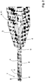
- Fig. 1 clearly shows that the ultrasound needle 1 protrudes slightly with its distal end 5 from the probe region 4 of the body 2, so that there due to the ultrasonic excitation an abrasive effect to destroy the tissue occurs.
- Fig. 1 further shows that the probe area 4 at the distal end 7 has two lateral exits 8 through which cooling / scavenging agents can exit into the body opening.
- the distal end 5 of the ultrasound needle 1 can flow around particularly well, with the liquid together with the separated tissue being sucked through the ultrasound needle 1 designed as a hollow needle to the proximal end 9 of the ultrasound needle 1.
- connection region 3 of the body 2 should be sufficiently elastic in order to push it over a corresponding connection region of the instrument, not shown.
- a clamping effect results from the elasticity of the material.
- the probe region 4 is slightly stiffened at least on the surface, namely by a special measure, which may include a coating and / or reaction and / or diffusion with a suitable material.
- a body 2 is indicated, whose probe area 4 is at least slightly stiffer than the connection area 3, although both areas are made of the same or similar material.
- Fig. 2 shows in the leaves can be seen in section the ultrasonic needle 1, which is traversed in the longitudinal direction with an inner channel 10.
- the distal end 5 of the ultrasonic needle 1 is equipped in the sense of an abrasive tool and serves with simultaneous ultrasonic excitation on the one hand for destruction the tissue and on the other hand for receiving and sucking the tissue pieces.
- the channel 10 can be made stepped.
- connection region 11 is provided for connection to a suitable hand-held device. This connection region is surrounded by the connection region 3 of the body 2 when it is used appropriately, as a result of which a secure operative connection can be established.
Landscapes
- Health & Medical Sciences (AREA)
- Ophthalmology & Optometry (AREA)
- Heart & Thoracic Surgery (AREA)
- Surgery (AREA)
- Engineering & Computer Science (AREA)
- Biomedical Technology (AREA)
- Nuclear Medicine, Radiotherapy & Molecular Imaging (AREA)
- Vascular Medicine (AREA)
- Life Sciences & Earth Sciences (AREA)
- Animal Behavior & Ethology (AREA)
- General Health & Medical Sciences (AREA)
- Public Health (AREA)
- Veterinary Medicine (AREA)
- Surgical Instruments (AREA)
- Infusion, Injection, And Reservoir Apparatuses (AREA)
Description
- Die Erfindung betrifft eine Hülle für ein medizinisches Instrument, insbesondere zum Zugang in den menschlichen oder tierischen Körper, beispielsweise in das Auge, vorzugsweise als Infusionsaufsatz für eine zum Zerkleinern und Entfernen von Gewebe dienende Ultraschallnadel, mit einem einen Anschlussbereich und einen Sondenbereich umfassenden Körper, der das Instrument bzw. die Nadel bis zu deren freien Ende mit geringem Abstand umgibt, so dass im Bereich zwischen dem Instrument bzw. der Nadel und dem Körper ein Fluidum förderbar ist, wobei der Körper vorzugsweise einteilig aus Gummi oder weichem Kunststoff gefertigt ist. Des Weiteren betrifft die Erfindung ein Verfahren zur Herstellung einer entsprechenden Hülle.
- Eine gattungsbildende Hülle ist aus der
WO 93/05716 - Hüllen bzw. Infusionsaufsätze der gattungsbildenden Art werden insbesondere bei Augenoperationen zum Zerstören und Entfernen des Linsenkörpers verwendet. Sie finden aber auch ihren Einsatz zum Entfernen von Ablagerungen in Arterien oder dergleichen. Entsprechend ihrem Einsatz dienen sie zum Einführen in den Körper durch künstliche Zugänge hindurch. Eine hinreichende Elastizität im Sondenbereich soll die Öffnungswunde schonen, insbesondere gegenüber einer möglicherweise überhitzten Ultraschallnadel im distalen Bereich.
- Der Abstand zwischen der Hülle bzw. dem Sondenbereich und der Ultraschallnadel dient zum Durchfluss einer kühlenden Flüssigkeit, die am distalen Ende über das Instrument bzw. die als Hohlkörper ausgeführte Ultraschallnadel abgesaugt wird.
- Bereits in der
WO 93/05716 WO 93/05716
Der vorliegenden Erfindung liegt daher die Aufgabe zugrunde, eine gattungsbildende Hülle, insbesondere einen gattungsbildenden Infusionsaufsatz, derart auszugestalten und weiterzubilden, dass er sich zum schonenden Einsatz bei höchster Betriebssicherheit ganz besonders im Ultraschallbetrieb eignet. Außerdem soll ein Verfahren zur Herstellung einer entsprechenden Hülle angegeben werden. - In Bezug auf das erfindungsgemäße Verfahren ist die zuvor genannte Aufgabe durch die Merkmale des Patentanspruchs 1 gelöst. Erfindungsgemäß ist erkannt worden, dass sich eine elastische Hülle zum zweckentsprechenden chirurgischen bzw. augenchirurgischen Einsatz dann besonders eignet, wenn der Sondenbereich zwar elastisch ausgeführt ist, jedoch durch bestimmte Maßnahmen zumindest an der Oberfläche versteift ist. Eine geeignete Maßnahme ist beispielsweise die Vorkehrung einer möglichst dünnen Beschichtung. Auch ist es denkbar, die Versteifung durch Reaktion oder Diffusion zumindest an der Oberfläche des Sondenbereichs hervorzurufen. Die erforderliche Elastizität zum zumindest geringfügigen Zurückschieben des Sondenbereichs ergibt sich aus dem gesamten Sondenbereich, wobei die Beschichtung oder Reaktion bzw. Diffusion zumindest an der Oberfläche zu einer Versteifung führt, so dass ein Kollaps eines zu weichen Sondenbereichs wirksam vermieden ist. So lässt sich die erforderliche Funktion in Form eines Ringkanals, beispielsweise um eine Ultraschallnadel herum, aufrechterhalten, wobei eine Freigabe des distalen Endes der Ultraschallnadel aufgrund der verbleibenden Elastizität gewährleistet ist.
Im Konkreten ist der Körper der Hülle aus Silikon hergestellt. Eine spritzgusstechnische Herstellung ist zu bevorzugen. Weiter ist es denkbar, dass der Anschlussbereich und der Sondenbereich aus unterschiedlichen Kunststoffen, insbesondere aus unterschiedlich harten Kunststoffen, gefertigt ist. Eine gleichzeitige Herstellung mit integralen Bestandteilen lässt sich im sogenannten Overmouldingverfahren realisieren.
In besonders vorteilhafter Weise ist die Versteifung des Sondenbereichs derart bemessen bzw. ausgelegt, dass im Ultraschallbetrieb des Instruments bzw. der Ultraschallnadel ein Knicken oder Einschnüren des Sondenbereichs weitestgehend verhindert ist, jedoch ein zumindest geringfügiges Zurückschieben des Sondenbereichs, weg vom distalen Ende des Instruments bzw. der Nadelspitze, möglich ist. Die Funktion der Hülle ist damit auf einfache Weise optimiert. - Zur Beschichtung bzw. Diffusion oder Reaktion könnte ein Material mit Nanopartikeln verwendet werden, wobei sich die Verwendung von Nanopartikeln insbesondere zur Einlagerung in eine offene Porosität des Materials der Hülle besonders eignet.
- Grundsätzlich lassen sich zur Beschichtung bzw. zur Erzeugung einer Reaktion oder Diffusion unterschiedlichste Materialien verwenden, wobei es lediglich auf das Ergebnis insoweit ankommt, als eine Versteifung des Sondenbereichs vorgenommen wird. Jedenfalls kann zur Beschichtung ein Kunststoff dienen, der zumindest an der Oberfläche eine Reaktion bzw. eine Brückenbildung oder Vernetzung hervorruft. Ebenso ist es denkbar, dass zur Beschichtung ein Metall verwendet wird, wobei das Metall aufgedampft, aufgesputtert oder sonst wie aufgebracht werden kann. Dabei reicht eine äußerst dünne Schicht bereits aus, um die erforderliche Versteifung des Sondenbereichs hervorzurufen.
- Zur Reaktion und/oder Diffusion lässt sich ebenso ein Kunststoff verwenden, wie auch bereits zu der zuvor erwähnten Oberflächenbeschichtung.
- In weiter vorteilhafter Weise lässt sich die Beschichtung bzw. das Aufbringen des zur Reaktion oder Diffusion dienenden Materials über ein Tauchbad oder durch Besprühen realisieren. Es könnte beispielsweise lediglich der Sondenbereich in das Bad eingetaucht oder mit dem zum Verspröden dienenden Kunststoff besprüht werden. Auch eine Art Pulverbeschichtung mit anschließender Wärmebehandlung ist denkbar.
- Das erfindungsgemäße Verfahren dient insbesondere zur Herstellung einer erfindungsgemäßen Hülle, wobei es darauf ankommt, dass zumindest der Sondenbereich, ganz oder teilweise, geringfügig versteift wird. Diese Versteifung kann durch eine Versprödung des Materials erzeugt werden.
- In Bezug auf das erfindungsgemäße Verfahren gelten die gleichen Ausführungen wie zu der erfindungsgemäßen Hülle. In Ergänzung zu den voranstehenden Ausführungen sei erwähnt, dass es von Vorteil ist, wenn das Material der Hülle bzw. des Körpers der Hülle vor dem Beschichten entfettet wird. Dazu kann vor dem eigentlichen Beschichten eine Anwendung in einem Ultraschallbad vorgenommen werden. Der Vorgang des Säuberns/Entfettens lässt sich dadurch begünstigen. Auch ist es denkbar, dass die Beschichtung bzw. das Tränken unter Ultraschalleinwirkung erfolgt, um nämlich einen besseren Kontakt zwischen der Oberfläche der Hülle bzw. des Sondenbereichs und dem zur Beschichtung dienenden Material hervorzurufen. Erfindungsgemäß wird die Hülle vor dem Beschichten mit einem Haftvermittler behandelt, um nämlich die Grenzflächenenergie zwischen dem Material der Hülle und dem zur Beschichtung dienenden Material zu reduzieren. Es gibt nun verschiedene Möglichkeiten die Lehre der vorliegenden Erfindung in vorteilhafter Weise auszugestalten und weiterzubilden. Dazu ist einerseits auf die dem Patentanspruch nachgeordneten Patentansprüche und andererseits auf die nachfolgende Erläuterung eines bevorzugten Ausführungsbeispiels der Erfindung anhand der Zeichnung zu verweisen. In Verbindung mit der Erläuterung des bevorzugten Ausführungsbeispiels der Erfindung anhand der Zeichnung werden auch im Allgemeinen bevorzugte Ausgestaltungen und Weiterbildungen der Lehre erläutert. In der Zeichnung zeigt
- Fig. 1
- in einer schematischen Ansicht ein Ausführungsbeispiel einer erfindungsgemäßen Hülle in Form eines Infusionsaufsatzes für eine zum Zerkleinern und Entfernen von Gewebe dienenden Ultraschallnadel, wobei in
Fig. 1 lediglich die Nadelspitze erkennbar ist und - Fig. 2
- den Gegenstand aus
Fig. 1 in gleicher Ansicht, jedoch geschnitten. -
Fig. 1 zeigt deutlich, dass die Ultraschallnadel 1 mit ihrem distalen Ende 5 aus dem Sondenbereich 4 des Körpers 2 geringfügig herausragt, damit dort aufgrund der Ultraschallerregung ein abrasiver Effekt zum Zerstören des Gewebes auftritt.Fig. 1 zeigt des Weiteren, dass der Sondenbereich 4 am distalen Ende 7 zwei seitliche Ausgänge 8 aufweist, durch die hindurch Kühl-/Spühlmittel in die Körperöffnung hinein austreten kann. Somit lässt sich das distale Ende 5 der Ultraschallnadel 1 besonders gut umspülen, wobei die Flüssigkeit nebst abgetrenntem Gewebe durch die als Hohlnadel ausgeführte Ultraschallnadel 1 hindurch zum proximalen Ende 9 der Ultraschallnadel 1 abgesaugt wird. - In Bezug auf die
Fig. 1 und2 sei an dieser Stelle angemerkt, dass der Anschlussbereich 3 des Körpers 2 hinreichend elastisch sein sollte, um diesen nämlich über einen entsprechenden Anschlussbereich des nicht gezeigten Instruments zu schieben. Eine Klemmwirkung ergibt sich aus der Elastizität des Materials. - Wäre der Sondenbereich 4 genauso elastisch wie der Anschlussbereich 3, bestünde die Gefahr, dass der Sondenbereich 4 auf der Ultraschallnadel 1 zu weit zurückgeschoben wird, wodurch Knicke oder Einschnürungen entstehen, die die Strömung des Kühlmittels unterbinden. Entsprechend ist der Sondenbereich 4 zumindest an der Oberfläche geringfügig versteift, nämlich durch eine besondere Maßnahme, die eine Beschichtung und/oder Reaktion und/oder Diffusion mit einem geeigneten Material umfassen kann. So ist in erfindungsgemäßer Weise ein Körper 2 angegeben, dessen Sondenbereich 4 zumindest geringfügig steifer ausgeführt ist als der Anschlussbereich 3, wenngleich beide Bereiche aus dem gleichen oder ähnlichen Material gefertigt sind.
-
Fig. 2 zeigt im lässt im Schnitt die Ultraschallnadel 1 erkennen, die in Längsrichtung mit einem inneren Kanal 10 durchzogen ist. - Das distale Ende 5 der Ultraschallnadel 1 ist im Sinne eines abrasiven Werkzeugs ausgestattet und dient bei gleichzeitiger Ultraschallerregung einerseits zur Zerstörung des Gewebes und andererseits zur Aufnahme und zum Absaugen der Gewebestücke.
- Der Kanal 10 kann gestuft ausgeführt sein.
- Am proximalen Ende 9 der Ultraschallnadel 1 ist ein Anschlussbereich 11 zum Anschließen an ein geeignetes Handgerät vorgesehen. Dieser Anschlussbereich ist bei zweckentsprechendem Einsatz durch den Anschlussbereich 3 des Körpers 2 umgeben, wodurch sich eine sichere Wirkverbindung herstellen lässt.
- Hinsichtlich weiterer vorteilhafter Ausgestaltungen der erfindungsgemäßen Hülle wird zur Vermeidung von Wiederholungen auf den allgemeinen Teil der Beschreibung sowie auf die Patentansprüche verwiesen.
- Schließlich sei ausdrücklich darauf hingewiesen, dass das voranstehend beschriebene Ausführungsbeispiel der erfindungsgemäßen Hülle lediglich zur Erörterung der beanspruchten Lehre dient, diese jedoch nicht auf das Ausführungsbeispiel einschränkt.
-
- 1
- Ultraschallnadel
- 2
- Körper
- 3
- Anschlussbereich (des Körpers)
- 4
- Sondenbereich (des Körpers)
- 5
- freies/distales Ende der Ultraschallnadel
- 6
- Ringkanal (zwischen Ultraschallnadel und Sondenbereich)
- 7
- distales Ende (des Sondenbereichs)
- 8
- seitlicher Ausgang (im Sondenbereich)
- 9
- proximales Ende (der Ultraschallnadel)
- 10
- Kanal (in der Ultraschallnadel)
- 11
- Anschlussbereich (der Ultraschallnadel)
Der Infusionsaufsatzes umfasst einen Körper 2 mit einem Anschlussbereich 3 zum Aufstecken auf ein in den Fig. nicht gezeigtes Instrument und einen Sondenbereich 4, der die Ultraschallnadel 1 bis zu deren freien/distalen Ende 5 mit Abstand umgibt, so dass zwischen der Ultraschallnadel 1 und dem Körper 2 bzw. dem Sondenbereich 4 ein Ringkanal 6 realisiert ist. Durch diesen Ringkanal 6 hindurch lässt sich ein Fluidum vom proximalen Ende bzw. Anschlussbereich 3 zum distalen Ende 7 durch den Sondenbereich 4 hindurch fördern.
Claims (4)
- Verfahren zur Herstellung einer Hülle für ein medizinisches Instrument, insbesondere zum Zugang in den menschlichen oder tierischen Körper, beispielsweise in das Auge, vorzugsweise als Infusionsaufsatz für eine zum Zerkleinern und Entfernen von Gewebe dienende Ultraschallnadel (1), wobei die Hülle einen Körper mit einem Anschlussbereich (3) und einem Sondenbereich (4) umfasst, der das Instrument bzw. die Nadel bis zu deren freien Ende (5) mit geringem Abstand umgibt, so dass im Bereich zwischen dem Instrument bzw. der Nadel und dem Körper (2) ein Fluidum förderbar ist, wobei der Körper (2) vorzugsweise einteilig aus Silikon gefertigt wird, dadurch gekennzeichnet, dass zumindest der Sondenbereich (4), ganz oder teilweise, durch Beschichtung zumindest an der Oberfläche geringfügig versteift wird, und dass die Hülle vor dem Beschichten mit einem Haftvermittler behandelt wird.
- Verfahren nach Anspruch 1, dadurch gekennzeichnet, dass die Versteifung derart bemessen bzw. ausgelegt wird, dass im Ultraschallbetrieb des Instruments bzw. der Ultraschallnadel (1) ein Knicken oder Einschnüren des Sondenbereichs (4) weitestgehend verhindert ist, jedoch ein geringfügiges Zurückschieben des Sondenbereichs (4), weg vom distalen Ende des Instruments bzw. der Nadelspitze, möglich ist.
- Verfahren nach Anspruch 1 oder 2, dadurch gekennzeichnet, dass zur Beschichtung ein Material mit Nanopartikeln verwendet wird,
beispielsweise aus Kunststoff oder Metall,
wobei im Falle einer metallischen Beschichtung das Metall aufgedampft oder aufgesputtert werden kann. - Verfahren nach einem der Ansprüche 1 bis 3, dadurch gekennzeichnet, dass die Hülle vor dem Beschichten entfettet und/oder
in einem Ultraschallbad behandelt wird und
dass die Beschichtung unter Ultraschalleinwirkung erfolgt.
Applications Claiming Priority (2)
| Application Number | Priority Date | Filing Date | Title |
|---|---|---|---|
| DE102008060868A DE102008060868A1 (de) | 2008-12-09 | 2008-12-09 | Hülle |
| PCT/DE2009/001525 WO2010066222A1 (de) | 2008-12-09 | 2009-11-02 | Hülle |
Publications (2)
| Publication Number | Publication Date |
|---|---|
| EP2293748A1 EP2293748A1 (de) | 2011-03-16 |
| EP2293748B1 true EP2293748B1 (de) | 2018-01-10 |
Family
ID=42115721
Family Applications (1)
| Application Number | Title | Priority Date | Filing Date |
|---|---|---|---|
| EP09798866.1A Active EP2293748B1 (de) | 2008-12-09 | 2009-11-02 | Verfahren zur herstellung einer hülle |
Country Status (3)
| Country | Link |
|---|---|
| EP (1) | EP2293748B1 (de) |
| DE (1) | DE102008060868A1 (de) |
| WO (1) | WO2010066222A1 (de) |
Families Citing this family (2)
| Publication number | Priority date | Publication date | Assignee | Title |
|---|---|---|---|---|
| DE102011012637B4 (de) * | 2011-02-28 | 2017-03-09 | Geuder Ag | Hülle für ein medizinisches Instrument |
| DE102011107676A1 (de) * | 2011-07-13 | 2013-01-17 | Geuder Ag | Medizinisches Werkzeug und Verfahren zur Herstellung eines medizinischen Werkzeugs |
Citations (1)
| Publication number | Priority date | Publication date | Assignee | Title |
|---|---|---|---|---|
| DE102004057382A1 (de) * | 2004-11-26 | 2006-06-01 | Huhtamaki Forchheim Zweigniederlassung Der Huhtamaki Deutschland Gmbh & Co. Kg | Verfahren zur Herstellung dünner Schichten eines Silikons, dünnes Silikon und Verwendung |
Family Cites Families (9)
| Publication number | Priority date | Publication date | Assignee | Title |
|---|---|---|---|---|
| US4054143A (en) * | 1975-04-26 | 1977-10-18 | Richard Wolf Gmbh | Single-pole coagulation forceps |
| US4897079A (en) * | 1988-07-22 | 1990-01-30 | Allergan, Inc. | Polymeric sleeve for surgical instruments |
| CA2071760A1 (en) | 1991-09-23 | 1993-03-24 | Alexander Ureche | Infusion sleeve for surgical ultrasonic apparatus |
| US5505693A (en) * | 1994-12-30 | 1996-04-09 | Mackool; Richard J. | Method and apparatus for reducing friction and heat generation by an ultrasonic device during surgery |
| WO1996038091A1 (en) * | 1995-06-02 | 1996-12-05 | Surgical Design Corporation | Phacoemulsification handpiece, sleeve, and tip |
| WO1998019730A1 (en) * | 1996-11-04 | 1998-05-14 | Sherwood Medical Company | Coated radially expandable dilator for use with gastrointestinal-type tubes |
| US5807310A (en) * | 1997-05-13 | 1998-09-15 | Nexus Medical System, Inc. Llc | Irrigation sleeve for an ultrasonic tip |
| US6033375A (en) * | 1997-12-23 | 2000-03-07 | Fibrasonics Inc. | Ultrasonic probe with isolated and teflon coated outer cannula |
| US6117151A (en) * | 1998-11-05 | 2000-09-12 | Circuit Tree Medical, Inc. | Eye incision temperature protecting sleeve |
-
2008
- 2008-12-09 DE DE102008060868A patent/DE102008060868A1/de not_active Withdrawn
-
2009
- 2009-11-02 EP EP09798866.1A patent/EP2293748B1/de active Active
- 2009-11-02 WO PCT/DE2009/001525 patent/WO2010066222A1/de not_active Ceased
Patent Citations (1)
| Publication number | Priority date | Publication date | Assignee | Title |
|---|---|---|---|---|
| DE102004057382A1 (de) * | 2004-11-26 | 2006-06-01 | Huhtamaki Forchheim Zweigniederlassung Der Huhtamaki Deutschland Gmbh & Co. Kg | Verfahren zur Herstellung dünner Schichten eines Silikons, dünnes Silikon und Verwendung |
Also Published As
| Publication number | Publication date |
|---|---|
| DE102008060868A1 (de) | 2010-06-10 |
| EP2293748A1 (de) | 2011-03-16 |
| WO2010066222A1 (de) | 2010-06-17 |
Similar Documents
| Publication | Publication Date | Title |
|---|---|---|
| DE3506738A1 (de) | Verfahren zur formung einer weichen, verformbaren spitze an dem distalen ende eines roehrenfoermigen thermoplastischen oder elastomeren katheters | |
| EP2785265A1 (de) | Vorrichtung zum ablösen wandständiger thromben aus einem körpergefäss | |
| WO2017080946A1 (de) | Dental-handwerkzeug | |
| EP2251142B1 (de) | Einwegdüse | |
| WO2018130529A1 (de) | Einstückiger spiegelsauger | |
| EP2110097B1 (de) | Dentalinstrument zur einmaligen Verwendung | |
| EP2105106B1 (de) | Medizinische Reinigungsvorrichtung zum Reinigen von innenliegenden Oberflächen | |
| WO2010066222A1 (de) | Hülle | |
| DE29501973U1 (de) | Vorrichtung zum Trennen einer biologischen Struktur | |
| EP2377562A2 (de) | Spülsystem zur Reinigung von Operationswunden | |
| EP4404868B1 (de) | Dentalmedizinische kanüle für dentalspritze zur abgabe von medien und herstellungsverfahren für eine dentalmedizinische kanüle | |
| DE102012103906A1 (de) | Vorrichtung und Verfahren zur Reinigung von rohrförmigen Hohlkörpern | |
| EP3852699B1 (de) | Instrument zum intraokularen eingriff | |
| DE10246207B4 (de) | Mikrodialysesonde mit spiralförmiger Leitung | |
| DE20009204U1 (de) | Katheteranordnung zur Stentimplantation | |
| DE202021100846U1 (de) | Spülanordnung | |
| EP3845209B1 (de) | Phaco-emulsifikationshandstück | |
| EP0414084A2 (de) | Vorrichtung zum Aufsprühen einer zahnärztlichen Abformmasse | |
| DE102009032186A1 (de) | Vorrichtung zum Einführen eines Mediums oder eines Instruments in den menschlichen Körper | |
| DE10335794A1 (de) | Kosmetikstäbchen | |
| DE102021202061A1 (de) | Medizinprodukt, Funktionsteil für ein Medizinprodukt und Verfahren zum Sterilisieren und/oder zum Herstellen von Sterilisationsbeständigkeit eines Medizinprodukts oder Funktionsteils | |
| WO2007065420A1 (de) | Katheterrohr | |
| DE102022105492A1 (de) | Laserapplizierte Markierungen für verbesserte sonografische und radiologische Bildgebung von medizinischen Vorrichtungen | |
| DE212011100187U1 (de) | Vorrichtung zur Reinigung des äußeren Gehörgangs | |
| DE102009030512A1 (de) | Vorrichtung zur dorsalen Stabilisierung der thorakolumbalen Wirbelsäule |
Legal Events
| Date | Code | Title | Description |
|---|---|---|---|
| PUAI | Public reference made under article 153(3) epc to a published international application that has entered the european phase |
Free format text: ORIGINAL CODE: 0009012 |
|
| 17P | Request for examination filed |
Effective date: 20101030 |
|
| AK | Designated contracting states |
Kind code of ref document: A1 Designated state(s): AT BE BG CH CY CZ DE DK EE ES FI FR GB GR HR HU IE IS IT LI LT LU LV MC MK MT NL NO PL PT RO SE SI SK SM TR |
|
| AX | Request for extension of the european patent |
Extension state: AL BA RS |
|
| 17Q | First examination report despatched |
Effective date: 20111004 |
|
| DAX | Request for extension of the european patent (deleted) | ||
| GRAP | Despatch of communication of intention to grant a patent |
Free format text: ORIGINAL CODE: EPIDOSNIGR1 |
|
| STAA | Information on the status of an ep patent application or granted ep patent |
Free format text: STATUS: GRANT OF PATENT IS INTENDED |
|
| INTG | Intention to grant announced |
Effective date: 20170718 |
|
| GRAS | Grant fee paid |
Free format text: ORIGINAL CODE: EPIDOSNIGR3 |
|
| GRAA | (expected) grant |
Free format text: ORIGINAL CODE: 0009210 |
|
| STAA | Information on the status of an ep patent application or granted ep patent |
Free format text: STATUS: THE PATENT HAS BEEN GRANTED |
|
| AK | Designated contracting states |
Kind code of ref document: B1 Designated state(s): AT BE BG CH CY CZ DE DK EE ES FI FR GB GR HR HU IE IS IT LI LT LU LV MC MK MT NL NO PL PT RO SE SI SK SM TR |
|
| REG | Reference to a national code |
Ref country code: GB Ref legal event code: FG4D Free format text: NOT ENGLISH |
|
| REG | Reference to a national code |
Ref country code: CH Ref legal event code: EP Ref country code: AT Ref legal event code: REF Ref document number: 961592 Country of ref document: AT Kind code of ref document: T Effective date: 20180115 |
|
| REG | Reference to a national code |
Ref country code: IE Ref legal event code: FG4D Free format text: LANGUAGE OF EP DOCUMENT: GERMAN |
|
| REG | Reference to a national code |
Ref country code: DE Ref legal event code: R096 Ref document number: 502009014674 Country of ref document: DE |
|
| REG | Reference to a national code |
Ref country code: NL Ref legal event code: FP |
|
| PG25 | Lapsed in a contracting state [announced via postgrant information from national office to epo] |
Ref country code: CY Free format text: LAPSE BECAUSE OF FAILURE TO SUBMIT A TRANSLATION OF THE DESCRIPTION OR TO PAY THE FEE WITHIN THE PRESCRIBED TIME-LIMIT Effective date: 20180110 Ref country code: LT Free format text: LAPSE BECAUSE OF FAILURE TO SUBMIT A TRANSLATION OF THE DESCRIPTION OR TO PAY THE FEE WITHIN THE PRESCRIBED TIME-LIMIT Effective date: 20180110 Ref country code: FI Free format text: LAPSE BECAUSE OF FAILURE TO SUBMIT A TRANSLATION OF THE DESCRIPTION OR TO PAY THE FEE WITHIN THE PRESCRIBED TIME-LIMIT Effective date: 20180110 Ref country code: ES Free format text: LAPSE BECAUSE OF FAILURE TO SUBMIT A TRANSLATION OF THE DESCRIPTION OR TO PAY THE FEE WITHIN THE PRESCRIBED TIME-LIMIT Effective date: 20180110 Ref country code: NO Free format text: LAPSE BECAUSE OF FAILURE TO SUBMIT A TRANSLATION OF THE DESCRIPTION OR TO PAY THE FEE WITHIN THE PRESCRIBED TIME-LIMIT Effective date: 20180410 Ref country code: HR Free format text: LAPSE BECAUSE OF FAILURE TO SUBMIT A TRANSLATION OF THE DESCRIPTION OR TO PAY THE FEE WITHIN THE PRESCRIBED TIME-LIMIT Effective date: 20180110 |
|
| PG25 | Lapsed in a contracting state [announced via postgrant information from national office to epo] |
Ref country code: IS Free format text: LAPSE BECAUSE OF FAILURE TO SUBMIT A TRANSLATION OF THE DESCRIPTION OR TO PAY THE FEE WITHIN THE PRESCRIBED TIME-LIMIT Effective date: 20180510 Ref country code: BG Free format text: LAPSE BECAUSE OF FAILURE TO SUBMIT A TRANSLATION OF THE DESCRIPTION OR TO PAY THE FEE WITHIN THE PRESCRIBED TIME-LIMIT Effective date: 20180410 Ref country code: SE Free format text: LAPSE BECAUSE OF FAILURE TO SUBMIT A TRANSLATION OF THE DESCRIPTION OR TO PAY THE FEE WITHIN THE PRESCRIBED TIME-LIMIT Effective date: 20180110 Ref country code: LV Free format text: LAPSE BECAUSE OF FAILURE TO SUBMIT A TRANSLATION OF THE DESCRIPTION OR TO PAY THE FEE WITHIN THE PRESCRIBED TIME-LIMIT Effective date: 20180110 Ref country code: GR Free format text: LAPSE BECAUSE OF FAILURE TO SUBMIT A TRANSLATION OF THE DESCRIPTION OR TO PAY THE FEE WITHIN THE PRESCRIBED TIME-LIMIT Effective date: 20180411 Ref country code: PL Free format text: LAPSE BECAUSE OF FAILURE TO SUBMIT A TRANSLATION OF THE DESCRIPTION OR TO PAY THE FEE WITHIN THE PRESCRIBED TIME-LIMIT Effective date: 20180110 |
|
| PG25 | Lapsed in a contracting state [announced via postgrant information from national office to epo] |
Ref country code: MT Free format text: LAPSE BECAUSE OF FAILURE TO SUBMIT A TRANSLATION OF THE DESCRIPTION OR TO PAY THE FEE WITHIN THE PRESCRIBED TIME-LIMIT Effective date: 20180110 |
|
| REG | Reference to a national code |
Ref country code: DE Ref legal event code: R097 Ref document number: 502009014674 Country of ref document: DE |
|
| PG25 | Lapsed in a contracting state [announced via postgrant information from national office to epo] |
Ref country code: EE Free format text: LAPSE BECAUSE OF FAILURE TO SUBMIT A TRANSLATION OF THE DESCRIPTION OR TO PAY THE FEE WITHIN THE PRESCRIBED TIME-LIMIT Effective date: 20180110 Ref country code: RO Free format text: LAPSE BECAUSE OF FAILURE TO SUBMIT A TRANSLATION OF THE DESCRIPTION OR TO PAY THE FEE WITHIN THE PRESCRIBED TIME-LIMIT Effective date: 20180110 |
|
| PLBE | No opposition filed within time limit |
Free format text: ORIGINAL CODE: 0009261 |
|
| STAA | Information on the status of an ep patent application or granted ep patent |
Free format text: STATUS: NO OPPOSITION FILED WITHIN TIME LIMIT |
|
| PG25 | Lapsed in a contracting state [announced via postgrant information from national office to epo] |
Ref country code: SM Free format text: LAPSE BECAUSE OF FAILURE TO SUBMIT A TRANSLATION OF THE DESCRIPTION OR TO PAY THE FEE WITHIN THE PRESCRIBED TIME-LIMIT Effective date: 20180110 Ref country code: DK Free format text: LAPSE BECAUSE OF FAILURE TO SUBMIT A TRANSLATION OF THE DESCRIPTION OR TO PAY THE FEE WITHIN THE PRESCRIBED TIME-LIMIT Effective date: 20180110 Ref country code: SK Free format text: LAPSE BECAUSE OF FAILURE TO SUBMIT A TRANSLATION OF THE DESCRIPTION OR TO PAY THE FEE WITHIN THE PRESCRIBED TIME-LIMIT Effective date: 20180110 Ref country code: CZ Free format text: LAPSE BECAUSE OF FAILURE TO SUBMIT A TRANSLATION OF THE DESCRIPTION OR TO PAY THE FEE WITHIN THE PRESCRIBED TIME-LIMIT Effective date: 20180110 |
|
| 26N | No opposition filed |
Effective date: 20181011 |
|
| PG25 | Lapsed in a contracting state [announced via postgrant information from national office to epo] |
Ref country code: SI Free format text: LAPSE BECAUSE OF FAILURE TO SUBMIT A TRANSLATION OF THE DESCRIPTION OR TO PAY THE FEE WITHIN THE PRESCRIBED TIME-LIMIT Effective date: 20180110 |
|
| PG25 | Lapsed in a contracting state [announced via postgrant information from national office to epo] |
Ref country code: LU Free format text: LAPSE BECAUSE OF NON-PAYMENT OF DUE FEES Effective date: 20181102 Ref country code: MC Free format text: LAPSE BECAUSE OF FAILURE TO SUBMIT A TRANSLATION OF THE DESCRIPTION OR TO PAY THE FEE WITHIN THE PRESCRIBED TIME-LIMIT Effective date: 20180110 |
|
| REG | Reference to a national code |
Ref country code: BE Ref legal event code: MM Effective date: 20181130 |
|
| REG | Reference to a national code |
Ref country code: IE Ref legal event code: MM4A |
|
| PG25 | Lapsed in a contracting state [announced via postgrant information from national office to epo] |
Ref country code: IE Free format text: LAPSE BECAUSE OF NON-PAYMENT OF DUE FEES Effective date: 20181102 |
|
| PG25 | Lapsed in a contracting state [announced via postgrant information from national office to epo] |
Ref country code: BE Free format text: LAPSE BECAUSE OF NON-PAYMENT OF DUE FEES Effective date: 20181130 |
|
| PG25 | Lapsed in a contracting state [announced via postgrant information from national office to epo] |
Ref country code: TR Free format text: LAPSE BECAUSE OF FAILURE TO SUBMIT A TRANSLATION OF THE DESCRIPTION OR TO PAY THE FEE WITHIN THE PRESCRIBED TIME-LIMIT Effective date: 20180110 |
|
| PG25 | Lapsed in a contracting state [announced via postgrant information from national office to epo] |
Ref country code: PT Free format text: LAPSE BECAUSE OF FAILURE TO SUBMIT A TRANSLATION OF THE DESCRIPTION OR TO PAY THE FEE WITHIN THE PRESCRIBED TIME-LIMIT Effective date: 20180110 |
|
| PG25 | Lapsed in a contracting state [announced via postgrant information from national office to epo] |
Ref country code: MK Free format text: LAPSE BECAUSE OF NON-PAYMENT OF DUE FEES Effective date: 20180110 Ref country code: HU Free format text: LAPSE BECAUSE OF FAILURE TO SUBMIT A TRANSLATION OF THE DESCRIPTION OR TO PAY THE FEE WITHIN THE PRESCRIBED TIME-LIMIT; INVALID AB INITIO Effective date: 20091102 |
|
| P01 | Opt-out of the competence of the unified patent court (upc) registered |
Effective date: 20230525 |
|
| PGFP | Annual fee paid to national office [announced via postgrant information from national office to epo] |
Ref country code: NL Payment date: 20241128 Year of fee payment: 16 |
|
| PGFP | Annual fee paid to national office [announced via postgrant information from national office to epo] |
Ref country code: GB Payment date: 20241218 Year of fee payment: 16 |
|
| PGFP | Annual fee paid to national office [announced via postgrant information from national office to epo] |
Ref country code: FR Payment date: 20241128 Year of fee payment: 16 |
|
| PGFP | Annual fee paid to national office [announced via postgrant information from national office to epo] |
Ref country code: AT Payment date: 20241213 Year of fee payment: 16 |
|
| PGFP | Annual fee paid to national office [announced via postgrant information from national office to epo] |
Ref country code: IT Payment date: 20241128 Year of fee payment: 16 |
|
| PGFP | Annual fee paid to national office [announced via postgrant information from national office to epo] |
Ref country code: CH Payment date: 20241219 Year of fee payment: 16 |
|
| PGFP | Annual fee paid to national office [announced via postgrant information from national office to epo] |
Ref country code: DE Payment date: 20250131 Year of fee payment: 16 |