EP2293628A1 - System und Verfahren zur Sendeleistungsregelung - Google Patents
System und Verfahren zur Sendeleistungsregelung Download PDFInfo
- Publication number
- EP2293628A1 EP2293628A1 EP10180369A EP10180369A EP2293628A1 EP 2293628 A1 EP2293628 A1 EP 2293628A1 EP 10180369 A EP10180369 A EP 10180369A EP 10180369 A EP10180369 A EP 10180369A EP 2293628 A1 EP2293628 A1 EP 2293628A1
- Authority
- EP
- European Patent Office
- Prior art keywords
- base station
- transmission power
- mobile station
- signal
- selection signal
- Prior art date
- Legal status (The legal status is an assumption and is not a legal conclusion. Google has not performed a legal analysis and makes no representation as to the accuracy of the status listed.)
- Granted
Links
- 230000005540 biological transmission Effects 0.000 title claims abstract description 171
- 238000000034 method Methods 0.000 title claims abstract description 31
- 230000001360 synchronised effect Effects 0.000 claims abstract description 6
- 230000008054 signal transmission Effects 0.000 abstract description 2
- 241001676573 Minium Species 0.000 abstract 1
- 238000010586 diagram Methods 0.000 description 5
- 238000004891 communication Methods 0.000 description 4
- 238000012544 monitoring process Methods 0.000 description 3
- 238000007796 conventional method Methods 0.000 description 2
- 230000001934 delay Effects 0.000 description 2
- 238000005562 fading Methods 0.000 description 2
- 238000010295 mobile communication Methods 0.000 description 2
- 230000010267 cellular communication Effects 0.000 description 1
- 230000001413 cellular effect Effects 0.000 description 1
- 238000005259 measurement Methods 0.000 description 1
- 239000000843 powder Substances 0.000 description 1
- 238000012545 processing Methods 0.000 description 1
Images


Classifications
-
- H—ELECTRICITY
- H04—ELECTRIC COMMUNICATION TECHNIQUE
- H04W—WIRELESS COMMUNICATION NETWORKS
- H04W52/00—Power management, e.g. TPC [Transmission Power Control], power saving or power classes
- H04W52/04—TPC
- H04W52/38—TPC being performed in particular situations
- H04W52/40—TPC being performed in particular situations during macro-diversity or soft handoff
-
- H—ELECTRICITY
- H04—ELECTRIC COMMUNICATION TECHNIQUE
- H04B—TRANSMISSION
- H04B7/00—Radio transmission systems, i.e. using radiation field
- H04B7/02—Diversity systems; Multi-antenna system, i.e. transmission or reception using multiple antennas
- H04B7/022—Site diversity; Macro-diversity
-
- H—ELECTRICITY
- H04—ELECTRIC COMMUNICATION TECHNIQUE
- H04W—WIRELESS COMMUNICATION NETWORKS
- H04W36/00—Hand-off or reselection arrangements
- H04W36/16—Performing reselection for specific purposes
- H04W36/18—Performing reselection for specific purposes for allowing seamless reselection, e.g. soft reselection
-
- H—ELECTRICITY
- H04—ELECTRIC COMMUNICATION TECHNIQUE
- H04W—WIRELESS COMMUNICATION NETWORKS
- H04W52/00—Power management, e.g. TPC [Transmission Power Control], power saving or power classes
- H04W52/04—TPC
- H04W52/18—TPC being performed according to specific parameters
- H04W52/24—TPC being performed according to specific parameters using SIR [Signal to Interference Ratio] or other wireless path parameters
-
- H—ELECTRICITY
- H04—ELECTRIC COMMUNICATION TECHNIQUE
- H04W—WIRELESS COMMUNICATION NETWORKS
- H04W52/00—Power management, e.g. TPC [Transmission Power Control], power saving or power classes
- H04W52/04—TPC
- H04W52/54—Signalisation aspects of the TPC commands, e.g. frame structure
Definitions
- the present invention relates to a cellular communications system, and more particularly to a transmission power control technique in a base station.
- CDMA code division multiple access
- soft handover is a well-known technique where a mobile station is simultaneously communicating with multiple base stations, allowing hitless connection switching by making a connection to a new base station while maintaining a connection to an old base station.
- Sort handover provides diversity, which is a method of using independent fading signals received on several transmission paths all carrying the same message to improve the reliability of the transmission.
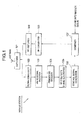
- a mobile station is communicating with multiple base stations for soft handover.
- a downlink signal from each of the base stations is received at an antenna and is transferred to a down converter 102 through a duplexer 101.
- the down converter 102 converts the received radiofrequency (rf) signal into a baseband signal and outputs it to a pilot signal receiver 103.
- the pilot signal receiver 103 detects a pilot signal from the received baseband signal and measures the intensity or quality thereof.
- a primary base station decision section 104 compares the intensity/quality measurements of the received signals to determine a base station transmitting a signal having the maximum intensity/quality as a primary base station to communicate with.
- a base station selection signal generator 105 generates a base station selection signal from the identification number of the primary base station.
- a control signal generator 106 generates control signals including a transmission power control signal and outputs the control signals to a combiner 107 together with the base station selection signal received from the base station selection signal generator 105.
- the combiner 107 combines the control signals and the base station selection signal with an uplink information signal to produce a transmission signal.
- the transmission signal is converted to an rf transmission signal by an up converter 108.
- the rf transmission signal is further amplified by an rf amplifier 109 and then transmitted as an uplink signal to the base stations through the duplexer 101.
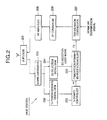
- Each of the base stations communicating with the mobile station receives the uplink signal including the base station selection signal from the mobile station.
- the uplink signal is received at an antenna and is transferred to a down converter 202 through a duplexer 201.
- the down converter 202 converts the received rf uplink signal to a baseband signal and outputs it to both a transmission power control signal demodulator 203 and a base station selection signal demodulator 204.
- the transmission power control signal demodulator 203 demodulates the transmission power control signal from the received baseband signal and outputs it to a transmission power controlled 205.
- the base station selection signal demodulator 204 demodulates the base station selection signal from the received baseband signal and outputs it to a primary/non-primary base station mode controller 206.
- the transmission power controller 205 produces an interim controlled transmission power value P1 depending on the transmission power control signal inputted from the transmission power control signal demodulator 203 and outputs the interim controlled transmission power value P1 to the primary/non-primary base station mode controller 206.
- the primary/non-primary base station mode controller 206 updates the interim controlled transmission power value P1 depending on the base station selection signal, to produce a final controlled transmission power value P2 and output it to a transmission controller 207.
- the details of the primary/non-primary base station mode controller 206 will be described later.
- the transmission controller 207 receives a downlink transmission signal and performs the output power control such that the transmission power of the downlink transmission signal is set to the final controlled transmission power value P2.
- the power-controlled downlink transmission signal is converted into radio frequency by an up converter 208.
- the rf downlink transmission signal is amplified by the rf amplifier 209 and then transmitted to the mobile station through the duplexer 201.
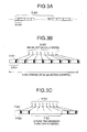
- a transmission signal between the mobile station and multiple base stations has a frame structure.
- a frame D-001 consists of Fn slots to which consecutive numbers from 0 to Fn-1 are assigned, respectively.
- the mobile station transmits the base station selection signal for soft handover to the base stations which it is communicating with.
- the base station selection signal is composed of a string of bits identifying each of the base stations. Since a plurality of bits are used to form a base station selection signal, redundancy can be provided, resulting in reduced transmission error due to noises and/or fading.
- a string of 8 bits identifying each of the base stations is called "a base station selection code word”.
- each part of the code word E-002 is assigned to the dedicated field E-001 of a different uplink slot E-003.
- the base station selection code word E-002 is divided into 8 parts (here, each part is one bit) and the respective 8 parts are transmitted by the dedicated fields E-001 of different slots E-003.
- a period of base station selection control E-004 is 8 slots, each of which has the desiccated field E-001 for storing a corresponding bit of the 8-bit base station selection code word E-002. It is possible to accommodate two or more bits of the base station selection code word E-002. The larger the number of bits to be accommodated, the shorter the period of base station selection control E-004.
- each base station and each mobile station measure intensities of pilot signals and interference signals received from adjacent cells at regular intervals in order to use them for handover control and call admission control.
- the uplink transmission of each mobile station connected to the base station is temporarily halted to allow the precise measuring of signals from outside cells. Further, there are some cases where the uplink transmission of a mobile station is halted during communication so as to suppress uplink interference in the case of packet transmission and no-voice transmission.
- the primary/non-primary base station mode controller 206 in each of the base stations updates the interim controlled transmission power value P1 depending on the base station selection code word E-002 to produce a final controlled transmission power value P2.
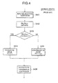
- the conventional base station mode control is performed as shown in Fig. 4 .
- the primary/non-primary base station mode controller 206 inputs the base station selection code word E-002 from the base station selection signal demodulator 204 (step S401) and detects the base station identification number BS_ID RSV from the base station selection code word E-002 (step S 402). Then, it is determined whether the base station identification number BS_ID RSV is identical to the identification number ID of its own (step S403).
- the transmission power selectively switches on and off depending on the base station selection code word E-002 received from the mobile station. Accordingly, multiple base stations are prevented from simultaneously transmitting the same signal to a single mobile station and thereby interference to adjacent cells is suppressed, resulting in improved communication capacity.
- the base station selection code word E-002 to be transmitted to the base stations is punctured in part or in entirety as shown in Fig. 3C .
- the base station selection code word E-002 is punctured in part and an incomplete code word F-002 is received at the base stations.
- Such a partial or entire loss of the base station selection code word E-002 results in substantially reduced reliability on base station selection control.
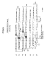
- a plurality of base stations transmit the same signal to a single mobile station.
- the transmission timing of the signal is adjusted so that the signals transmitted by the base stations arrive at the mobile station within an acceptable time deviation. Since propagation distances from the mobile station to the base stations vary from base station to base station, the respective transmission timings of the base stations are different. On the other hand, the base stations also receive the uplink signal from the mobile station at different timings due to the different propagation distances.
- a time slot is denoted by reference symbol G-001 and each transmission signal has a frame structure where 15 slots are numbered from 0 to 14.
- two base stations 1 and 2 transmit downlink transmission signals G-002 and G-003 to the mobile station with the respective transmission timings (propagation delays; D1 and D2) adjusted so that the downlink transmission signals arrive at the mobile station within an acceptable time deviation.
- the mobile station receives the downlink transmission signals G-002 as a downlink reception signal G-004 from the base station 1 and, at the approximately same time, receives the downlink transmission signals G-003 as a downlink reception signal G-005 from the base stations 2.
- the mobile station transmits an uplink transmission signal G-006 to the base stations 1 and 2 a time period of transmission timing offset T TR after the downlink reception signals G-004 and G-005 have been received.
- the uplink transmission signal G-006 includes the base station selection code word such that respective parts of the base station selection code word are conveyed in the dedicated fields as shown in Fig. 3B .
- the base station 2 receives the uplink transmission signal G-006 as an uplink reception signal G-007 with a propagation delay time of D3 and the base station 1 receives the uplink transmission signal G-006 as an uplink reception signal G-008 with a propagation delay time of D4.
- the base station 2 starts the primary/non-primary BS mode update operation as shown in Fig. 4 when receiving the last part of the base station, selection code word stored in the dedicated field G-020 In the slot numbered 14 of the uplink reception signal G-007.
- the timing of receiving the last part of the base station selection code word falls into the subsequent slot numbered 0. Therefore, the actual primary/non-primary mode update is performed at the further subsequent slot G-017 numbered 1.
- the base station 1 starts the primary/non-primary BS mode update operation as shown in Fig. 4 when receiving the last part of the base station selection code word stored in the dedicated field G-021 in the slot numbered 14 of the uplink reception signal G-008.
- the timing of receiving the last part of the base station selection code word falls into the next slot but one, that is numbered 1. Therefore, the actual primary/non-primary mode update is performed at the further next slot numbered 2.
- the primary base station update timing of the base station 1 is the slot G-018 numbered 2 and that of the base station 2 is the slot G-019 numbered 1. Since the BS selection code word is transmitted during a period of base station selection control, variation in BS mode update timing may cause loss of a downlink signal. To avoid such a signal loss, the mobile station needs an added circuit for monitoring the BS mode update timing at all times.
- An object of the present invention is to provide a transmission power control method and system allowing stable and reliable signal transmission.
- Another object of the present invention is to provide a primary base station mode update method ensuring stable and reliable operation in case of loss of a base station selection signal.
- Still another object of the present invention is to provide a primary base station mode update method allowing synchronization among the mode update timings of base stations communicating with a mobile station.
- a method for controlling transmission power of a downlink signal from a base station to a mobile station depending on a base station selection signal includes the steps of: at each of the base stations, receiving the base stations selection signal from the mobile station; measuring an amount of loss of the base station selection signal; determining whether the amount of loss of the base station selection signal exceeds a threshold; when the amount of loss of the base station selection signal does not exceed the threshold, setting the transmission power of the downlink signal to a selected one of a normally controlled level and a minimum level depending on the base station selection signal; and when the amount of loss of the base station selection signal exceeds the threshold, setting the transmission power of the downlink signal to the normally controlled level.
- the amount of loss of the base station selection signal may be a number of erroneously received bits in the base station selection signal.
- the amount of loss of the base station selection signal may be a ratio of a punctured length to a length of the base station selection signal.
- the threshold may vary depending on a length of the base station selection signal. The threshold may vary depending on the length of the base station selection signal.
- a method for controlling transmission power of a downlink signal which is transmitted in frames from a base station to a mobile station depending on a base station selection signal wherein the mobile station selects at least one primary base station among a plurality of base stations which are connected to the mobile station for soft handover to produce the base station selection signal designating said at least one primary base station, wherein an uplink signal including the base station selection signal is transmitted in frames to the base stations
- the method includes the steps of: at each of the base stations, a) receiving the uplink signal including the base station selection signal from the mobile station; b) determining a transmission power update timing so that the downlink signal received at the mobile station changes in transmission power at a predetermined timing synchronized with that of other base stations; and o) when reaching the transmission power update timing, setting the transmission power of the downlink signal to a selected one of a normally controlled level and a minimum level depending on the base station selection signal.
- Each frame of the uplink signal and the downlink signal may be composed of a plurality of time slots which are numbered consecutively, wherein the transmission power update timing in each of the base stations is represented by a number of same time slot.
- the time slot number indicating the transmission power update timing may be determined by delaying a receiving time of the base station selection signal by an amount of time determined so that the downlink signal received at the mobile station changes in transmission power at same timing.
- the time slot number indicating the transmission power update timing is preferably determined by j + Tos mod Fn , where j is number of a time slot indicating a last portion of the base station selection signal, Tos is waiting time for transmission power update.
- Fn is number of slots included in one frame, and mod is an operator whose result is the remainder of a division operation.
- the waiting time Tos may vary depending on a propagation delay between the base station and the mobile station.
- the waiting time Tos may vary depending on the time slot number j.
- the base station mode when the amount of loss of a base station selection signal received from a mobile station exceeds a predetermined level, the base station mode does not reduce the transmission power of the downlink signal regardless of whether the base station selection signal instructs the base station itself to be the primary base station or not. Therefore, base station selection error due to a low-reliable base station selection signal can be avoided. Especially, in the case where a base station is designated as the primary base station, it is avoided that the base station erroneously reduces or switches off the transmission power.
- the update timings of the base stations are in synchronization with each other in the downlink signal received at the mobile station, loss of a downlink signal caused by loss of synchronism can be avoided without the need of an added circuit for monitoring the mode update timing at the mobile station.
- the primary/non-primary base station mode controller 206 in each of the base stations updates the interim controlled transmission, power value P1 depending on the base station selection code word E-002 to produce a final controlled transmission power value P2.
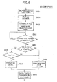
- a first embodiment of the present invention controls the transmission power taking into consideration the amount of loss of a base station selection signal or code word.
- the primary/non-primary base station mode controller 206 inputs the base station selection code word from the base station selection signal demodulator 204 (step S601) and measures the amount of loss of the base station selection code word (step S602).
- the amount of loss of the base station selection code word may be the number of punctured bits as shown in Fig. 3C or the ratio of the number of punctured bits to the number of all bits of the base station selection code word.
- L CW the amount of loss of the base station selection code word is denoted by L CW .
- the threshold L TH may vary depending on the length of the base station selection code word.
- step S603 If L cw is equal to or lower than L TH (NO at step S603), then the base station identification number BS_ID nsv is detected from the base station selection code word (step S605). Then, it is determined whether the base station identification number BS_ID RSV is identical to the identification number ID of its own (step S606).
- the base station identification number BS_ID RSV is not identical to the own identification number ID (NO at step S606), it may be further determined whether the reception quality of the base station selection code word satisfies a predetermined level. If the reception quality does not satisfy the predetermined level, then it is determined that the demodulated base station selection code word is not sufficiently reliable, and the final controlled transmission power value P2 may be set to the interim controlled transmission power value P1 (step S604).
- the transmission power is not suppressed regardless of whether the base station itself is designated as the primary base station or not.
- a second embodiment of the present invention controls the BS mode update timing so that synchronization among the primary/non-primary mode update timings of base stations is achieved.
- the primary/non-primary base station mode controller 206 inputs the base station selection code word from the base stations selection signal demodulator 204 (step S701) and detects the base station identification number B5_ID RSV from the base station selection code word E-002 (step S702). Then, variable is set to the number of a current slot and variable j is set to the number of a slot conveying the last part of the base station selection code word (step S703) .
- the predetermined minimum transmission power value P MIN may be 0.
- the final controlled transmission power value P2 is output to the transmission controller 207 (step S708).
- the base station identification number BS_ID RSV is not identical to the own identification number ID (NO at step S705), it may be further determined whether the reception quality of the base station selection code word satisfies a predetermined level. If the reception quality does not satisfy the predetermined level, then it is determined that the demodulated base station selection code word is not sufficiently reliable, and the final controlled transmission power value P2 may be set to the interim controlled transmission power value P1 (step S706).
- Fn 15
- D1 and D2 transmission timings
- the mobile station receives the downlink transmission signals J-002 as a downlink reception signal J-004 from the base station 1 and, at the approximately same time, receives the downlink transmission signals J-003 as a downlink reception signal J-005 from the base station 2.
- the mobile station transmits an uplink transmission signal J-006 to the base stations 1 and 2 a time period of transmission timing offset T TR after the downlink reception signals J-004 and J-005 have been received.
- the uplink transmission signal J-006 includes the base station selection code word such that respective parts of the base station selection code word are conveyed in the dedicated fields as shown in Fig. 3B .
- the base station 2 receives the uplink transmission signal J-006 as an uplink reception signal J-007 with a propagation delay time of D3 and the base station 1 receives the uplink transmission signal J-006 as an uplink reception signal J-008 with a propagation delay time of D4.
- the primary base station update timing of the base station 1 is in synchronization with that of the base station 2.
- the waiting time Tos is as short as possible to achieve high-speed mode switching. Since the propagation delay and processing delay in a base station may vary, it is possible to make the waiting time Tos variable during communication.
- the waiting time Tos may be varied depending on the number j of the slot conveying the last part of the base station selection code word.
- the primary base station mode update timing at the mobile station can be set to a desired timing.
- a third embodiment of the present invention is a combination of the first and second embodiments. Steps S901-S905 are the same as the steps S701-S705 of Fig. 7 , respectively. If the base station identification number BS_ID REV is identical to the own identification number ID (YES at step S905), then it is determined whether the amount of loss of the base station selection code word, L cw ,is greater than a threshold L TH (step S906).
- the final controlled transmission power value P2 is output to the transmission controller 207 (step S909).
- the base station identification number BS_ID KSV is not identical to the own identification number ID (NO at step S905), it may be further determined whether the reception quality of the base station selection code word satisfies a predetermined level. If the reception quality does not satisfy the predetermined level, then it is determined that the demodulated base station selection code word is not sufficiently reliable, and the final controlled transmission power value P2 may be set to the interim controlled transmission power value P1 (step S907).
- the base station mode is set to the primary mode regardless of whether the base station selection signal instructs the base station itself to be the primary base station or not. Therefore, such a decision error that the base station is erroneously set to the non-primary base station mode due to reception error can be effectively eliminated, resulting in stable and reliable quality of a downlink signal from the base station to the mobile station.
- the invention further relates to the following items:
Applications Claiming Priority (3)
| Application Number | Priority Date | Filing Date | Title |
|---|---|---|---|
| JP35341899A JP3365379B2 (ja) | 1999-12-13 | 1999-12-13 | 基地局選択型送信電力制御方法及び基地局装置 |
| EP00123392A EP1109330B1 (de) | 1999-12-13 | 2000-10-31 | System und Verfahren zur Sendeleistungsregelung |
| EP04017733A EP1478102B1 (de) | 1999-12-13 | 2000-10-31 | System und Verfahren zur Sendeleistungsregelung |
Related Parent Applications (4)
| Application Number | Title | Priority Date | Filing Date |
|---|---|---|---|
| EP00123392A Division EP1109330B1 (de) | 1999-12-13 | 2000-10-31 | System und Verfahren zur Sendeleistungsregelung |
| EP00123392.3 Division | 2000-10-31 | ||
| EP04017733A Division EP1478102B1 (de) | 1999-12-13 | 2000-10-31 | System und Verfahren zur Sendeleistungsregelung |
| EP04017733.9 Division | 2004-07-27 |
Publications (2)
| Publication Number | Publication Date |
|---|---|
| EP2293628A1 true EP2293628A1 (de) | 2011-03-09 |
| EP2293628B1 EP2293628B1 (de) | 2018-04-04 |
Family
ID=18430713
Family Applications (5)
| Application Number | Title | Priority Date | Filing Date |
|---|---|---|---|
| EP10182024.9A Expired - Lifetime EP2296411B1 (de) | 1999-12-13 | 2000-10-31 | System und Verfahren zur Sendeleistungsregelung |
| EP04017733A Expired - Lifetime EP1478102B1 (de) | 1999-12-13 | 2000-10-31 | System und Verfahren zur Sendeleistungsregelung |
| EP06126923.9A Expired - Lifetime EP1770872B1 (de) | 1999-12-13 | 2000-10-31 | System und Verfahren zur Sendeleistungsregelung |
| EP10180369.0A Expired - Lifetime EP2293628B1 (de) | 1999-12-13 | 2000-10-31 | System und Verfahren zur Sendeleistungsregelung |
| EP00123392A Expired - Lifetime EP1109330B1 (de) | 1999-12-13 | 2000-10-31 | System und Verfahren zur Sendeleistungsregelung |
Family Applications Before (3)
| Application Number | Title | Priority Date | Filing Date |
|---|---|---|---|
| EP10182024.9A Expired - Lifetime EP2296411B1 (de) | 1999-12-13 | 2000-10-31 | System und Verfahren zur Sendeleistungsregelung |
| EP04017733A Expired - Lifetime EP1478102B1 (de) | 1999-12-13 | 2000-10-31 | System und Verfahren zur Sendeleistungsregelung |
| EP06126923.9A Expired - Lifetime EP1770872B1 (de) | 1999-12-13 | 2000-10-31 | System und Verfahren zur Sendeleistungsregelung |
Family Applications After (1)
| Application Number | Title | Priority Date | Filing Date |
|---|---|---|---|
| EP00123392A Expired - Lifetime EP1109330B1 (de) | 1999-12-13 | 2000-10-31 | System und Verfahren zur Sendeleistungsregelung |
Country Status (6)
| Country | Link |
|---|---|
| US (4) | US6847818B1 (de) |
| EP (5) | EP2296411B1 (de) |
| JP (1) | JP3365379B2 (de) |
| KR (1) | KR100353746B1 (de) |
| CA (1) | CA2324727C (de) |
| DE (1) | DE60034759T2 (de) |
Families Citing this family (22)
| Publication number | Priority date | Publication date | Assignee | Title |
|---|---|---|---|---|
| MXPA03000798A (es) | 2000-07-27 | 2004-03-18 | Interdigital Tech Corp | Asignacion de ranura de tiempo hacia y desde el satelite, adaptable en un sistema de comunicaciones de acceso multiple de division de tiempo/acceso multiple de division de codigo, inalambrico hibrido. |
| JP3543323B2 (ja) * | 2001-02-14 | 2004-07-14 | 日本電気株式会社 | 基地局送信制御方法、セルラシステム及び基地局 |
| CN1162028C (zh) * | 2001-07-18 | 2004-08-11 | 华为技术有限公司 | 一种基站选择分集发射下的主小区识别方法 |
| GB0120033D0 (en) * | 2001-08-16 | 2001-10-10 | Fujitsu Ltd | Cell selection |
| US6591109B2 (en) * | 2001-08-17 | 2003-07-08 | Interdigital Technology Corporation | Cross cell user equipment interference reduction in a time division duplex communication system using code division multiple access |
| JP4012391B2 (ja) * | 2001-10-30 | 2007-11-21 | 株式会社エヌ・ティ・ティ・ドコモ | 移動局、移動通信システム、ハンドオーバー制御方法、ハンドオーバー制御プログラム、及び記録媒体 |
| GB2382956B (en) | 2001-12-05 | 2006-03-01 | Ipwireless Inc | Method and arrangement for power control |
| US7280842B2 (en) | 2001-12-17 | 2007-10-09 | Marvell International Ltd. | Wireless communication device and method for communicating in site selection diversity mode |
| US20030114179A1 (en) * | 2001-12-17 | 2003-06-19 | D.S.P.C. Technologies Ltd. | Method and apparatus for generating a quality measure target value based on channel conditions |
| JP4147780B2 (ja) * | 2002-02-12 | 2008-09-10 | 日本電気株式会社 | 品質しきい値設定方法及びそれを用いた通信制御装置 |
| JP4014893B2 (ja) * | 2002-03-01 | 2007-11-28 | 株式会社エヌ・ティ・ティ・ドコモ | マルチホップ接続用の無線通信システム、無線通信方法、これに用いる無線局 |
| US7515883B1 (en) | 2002-12-16 | 2009-04-07 | Marvell D.S.P.C. Ltd. | Wireless communication device and method for communicating in site selection diversity mode |
| KR100964669B1 (ko) * | 2003-05-10 | 2010-06-22 | 엘지전자 주식회사 | 고속 패킷 데이터 이동 통신 시스템 및 이 이동 통신시스템에서 데이터를 전송하는 방법 |
| US7953411B1 (en) * | 2004-06-09 | 2011-05-31 | Zte (Usa) Inc. | Virtual soft hand over in OFDM and OFDMA wireless communication network |
| US7536626B2 (en) * | 2004-06-18 | 2009-05-19 | Qualcomm Incorporated | Power control using erasure techniques |
| PL1667338T3 (pl) * | 2004-12-02 | 2008-01-31 | Swisscom Ag | Sieć telefonii komórkowej i sposób utworzenia stacji bazowej sieci telefonii komórkowej w urządzeniu zasilanym z sieci elektrycznej |
| US20070110035A1 (en) * | 2005-11-14 | 2007-05-17 | Broadcom Corporation, A California Corporation | Network nodes cooperatively routing traffic flow amongst wired and wireless networks |
| US7647050B2 (en) * | 2005-12-28 | 2010-01-12 | Alcatel-Lucent Usa Inc. | Method of adjusting a power level of communications over a channel in a wirelss communications network |
| WO2009044458A1 (ja) * | 2007-10-02 | 2009-04-09 | Fujitsu Limited | ハンドオーバ制御装置、移動局、基地局、ハンドオーバ制御サーバおよびハンドオーバ制御方法 |
| WO2010118582A1 (zh) | 2009-04-17 | 2010-10-21 | 华为技术有限公司 | 一种下行小区间干扰协调方法和基站 |
| CN102545992B (zh) * | 2011-12-21 | 2014-07-23 | 北京邮电大学 | Df中继系统的最优中继选择和功率分配方法 |
| JP2017085473A (ja) * | 2015-10-30 | 2017-05-18 | 富士通株式会社 | 伝送システム、無線装置および同期確立方法 |
Citations (3)
| Publication number | Priority date | Publication date | Assignee | Title |
|---|---|---|---|---|
| WO1998049785A1 (en) * | 1997-04-25 | 1998-11-05 | Qualcomm Incorporated | Method of and apparatus for controlling transmission power in a communication system |
| WO1999031819A1 (en) * | 1997-12-15 | 1999-06-24 | Telefonaktiebolaget Lm Ericsson (Publ) | Base station transmit power control in a cdma cellular telephone system |
| EP0936751A2 (de) * | 1998-02-16 | 1999-08-18 | Nec Corporation | Basisstation Sendeleistungsregelung während weichem Weiterreichen, Mobilsstation und Basisstation |
Family Cites Families (6)
| Publication number | Priority date | Publication date | Assignee | Title |
|---|---|---|---|---|
| JP2911090B2 (ja) * | 1993-09-29 | 1999-06-23 | エヌ・ティ・ティ移動通信網株式会社 | 移動通信の基地局装置及び移動局装置 |
| JP2739850B2 (ja) * | 1995-10-11 | 1998-04-15 | 日本電気株式会社 | 移動体通信システム |
| US6141555A (en) * | 1997-06-09 | 2000-10-31 | Nec Corporation | Cellular communication system, and mobile and base stations used in the same |
| US6104933A (en) * | 1997-06-23 | 2000-08-15 | Telefonaktiebolaget Lm Ericsson | Method and apparatus for control of base stations in macro diversity radio systems |
| JP3147850B2 (ja) | 1998-03-26 | 2001-03-19 | 日本電気株式会社 | 移動通信システム及びその通信制御方法並びにそれに使用する基地局及び移動局 |
| JP3750390B2 (ja) * | 1999-01-08 | 2006-03-01 | 日本電気株式会社 | 移動体通信における呼制御方法及びそのシステム |
-
1999
- 1999-12-13 JP JP35341899A patent/JP3365379B2/ja not_active Expired - Lifetime
-
2000
- 2000-10-30 CA CA002324727A patent/CA2324727C/en not_active Expired - Lifetime
- 2000-10-31 US US09/703,052 patent/US6847818B1/en not_active Expired - Lifetime
- 2000-10-31 EP EP10182024.9A patent/EP2296411B1/de not_active Expired - Lifetime
- 2000-10-31 KR KR1020000064230A patent/KR100353746B1/ko active IP Right Grant
- 2000-10-31 EP EP04017733A patent/EP1478102B1/de not_active Expired - Lifetime
- 2000-10-31 EP EP06126923.9A patent/EP1770872B1/de not_active Expired - Lifetime
- 2000-10-31 DE DE60034759T patent/DE60034759T2/de not_active Expired - Lifetime
- 2000-10-31 EP EP10180369.0A patent/EP2293628B1/de not_active Expired - Lifetime
- 2000-10-31 EP EP00123392A patent/EP1109330B1/de not_active Expired - Lifetime
-
2004
- 2004-01-23 US US10/762,356 patent/US7242959B2/en not_active Expired - Lifetime
-
2007
- 2007-06-05 US US11/758,026 patent/US7912493B2/en not_active Expired - Fee Related
-
2011
- 2011-02-10 US US13/024,372 patent/US8478330B2/en not_active Expired - Lifetime
Patent Citations (3)
| Publication number | Priority date | Publication date | Assignee | Title |
|---|---|---|---|---|
| WO1998049785A1 (en) * | 1997-04-25 | 1998-11-05 | Qualcomm Incorporated | Method of and apparatus for controlling transmission power in a communication system |
| WO1999031819A1 (en) * | 1997-12-15 | 1999-06-24 | Telefonaktiebolaget Lm Ericsson (Publ) | Base station transmit power control in a cdma cellular telephone system |
| EP0936751A2 (de) * | 1998-02-16 | 1999-08-18 | Nec Corporation | Basisstation Sendeleistungsregelung während weichem Weiterreichen, Mobilsstation und Basisstation |
Non-Patent Citations (1)
| Title |
|---|
| FURUKAWA: "RCS97-218", February 1998, article "Technical Report of Institute of Electronics, Information and Communication Engineers", pages: 40 |
Also Published As
| Publication number | Publication date |
|---|---|
| JP3365379B2 (ja) | 2003-01-08 |
| US8478330B2 (en) | 2013-07-02 |
| KR100353746B1 (ko) | 2002-09-28 |
| US20070232315A1 (en) | 2007-10-04 |
| US7242959B2 (en) | 2007-07-10 |
| EP1478102B1 (de) | 2011-05-18 |
| EP1770872A3 (de) | 2013-09-11 |
| US20110130145A1 (en) | 2011-06-02 |
| EP1770872B1 (de) | 2019-08-28 |
| EP2296411A1 (de) | 2011-03-16 |
| EP1109330A2 (de) | 2001-06-20 |
| US6847818B1 (en) | 2005-01-25 |
| EP1478102A1 (de) | 2004-11-17 |
| EP2296411B1 (de) | 2015-04-01 |
| CA2324727C (en) | 2004-12-07 |
| EP1109330B1 (de) | 2007-05-09 |
| US20040152483A1 (en) | 2004-08-05 |
| KR20010060230A (ko) | 2001-07-06 |
| US7912493B2 (en) | 2011-03-22 |
| EP1770872A2 (de) | 2007-04-04 |
| EP1109330A3 (de) | 2004-01-02 |
| CA2324727A1 (en) | 2001-06-13 |
| JP2001169328A (ja) | 2001-06-22 |
| DE60034759T2 (de) | 2008-01-17 |
| DE60034759D1 (de) | 2007-06-21 |
| EP2293628B1 (de) | 2018-04-04 |
Similar Documents
| Publication | Publication Date | Title |
|---|---|---|
| US8478330B2 (en) | Transmission power control method and system | |
| RU2233035C2 (ru) | Устройство и способ управления мощностью для широкополосной системы связи множественного доступа с кодовым разделением каналов, использующей схему пакетного доступа к высокоскоростной прямой линии связи | |
| US6026081A (en) | Method of controlling power on forward link in a cellular | |
| EP1890508B1 (de) | Verfahren und mobiles endgerät zur steuerung der zellsuche | |
| KR100441330B1 (ko) | 기지국 장치, 무선 통신 시스템 및 핸드오버 제어 방법 | |
| US7254413B2 (en) | Method and system of transmission power control | |
| KR100734452B1 (ko) | 셀룰러 시스템, 기지국 제어 장치, 이동국 및 이들에이용하는 송신 전력 제어 방법 | |
| JP2002010313A (ja) | 移動通信制御方法、セルラシステム、移動局、基地局及び基地局制御装置 | |
| JPH11355200A (ja) | 移動通信システム及びその通信制御方法並びにそれに用いる基地局及び移動局 | |
| US6907014B1 (en) | Apparatus and method for TDMA-TDD based transmission/reception | |
| EP1626510A2 (de) | Mobilkommunikationssystem und Verfahren zur Sendeleistungsregelung in der Abwärtsrichtung | |
| EP1119117A1 (de) | Basisstation, übertragungsendgerät und verfahren zur steuerung der übertragungsleistung | |
| US20020160716A1 (en) | Mobile station apparatus and radio communication method | |
| US6678530B1 (en) | Dynamic power control of a channel signal | |
| CA2452165C (en) | Transmission power control method and system | |
| JP3788307B2 (ja) | 基地局選択型送信電力制御方法及び基地局装置 | |
| JP4604611B2 (ja) | 基地局選択型送信電力制御方法、基地局装置及び移動局 | |
| US7171232B2 (en) | Method of selecting a cell to connect by radio with a mobile station and a mobile communications terminal therefor |
Legal Events
| Date | Code | Title | Description |
|---|---|---|---|
| PUAI | Public reference made under article 153(3) epc to a published international application that has entered the european phase |
Free format text: ORIGINAL CODE: 0009012 |
|
| AC | Divisional application: reference to earlier application |
Ref document number: 1478102 Country of ref document: EP Kind code of ref document: P Ref document number: 1109330 Country of ref document: EP Kind code of ref document: P |
|
| AK | Designated contracting states |
Kind code of ref document: A1 Designated state(s): DE FI FR GB IT SE |
|
| 17P | Request for examination filed |
Effective date: 20110907 |
|
| REG | Reference to a national code |
Ref country code: HK Ref legal event code: DE Ref document number: 1153336 Country of ref document: HK |
|
| 17Q | First examination report despatched |
Effective date: 20130814 |
|
| GRAP | Despatch of communication of intention to grant a patent |
Free format text: ORIGINAL CODE: EPIDOSNIGR1 |
|
| RIC1 | Information provided on ipc code assigned before grant |
Ipc: H04B 7/022 20170101ALI20171108BHEP Ipc: H04W 52/40 20090101AFI20171108BHEP Ipc: H04W 52/54 20090101ALI20171108BHEP Ipc: H04W 52/24 20090101ALI20171108BHEP Ipc: H04W 36/18 20090101ALI20171108BHEP |
|
| INTG | Intention to grant announced |
Effective date: 20171129 |
|
| GRAS | Grant fee paid |
Free format text: ORIGINAL CODE: EPIDOSNIGR3 |
|
| GRAA | (expected) grant |
Free format text: ORIGINAL CODE: 0009210 |
|
| AC | Divisional application: reference to earlier application |
Ref document number: 1109330 Country of ref document: EP Kind code of ref document: P Ref document number: 1478102 Country of ref document: EP Kind code of ref document: P |
|
| AK | Designated contracting states |
Kind code of ref document: B1 Designated state(s): DE FI FR GB IT SE |
|
| REG | Reference to a national code |
Ref country code: GB Ref legal event code: FG4D |
|
| REG | Reference to a national code |
Ref country code: DE Ref legal event code: R096 Ref document number: 60049802 Country of ref document: DE |
|
| REG | Reference to a national code |
Ref country code: SE Ref legal event code: TRGR |
|
| REG | Reference to a national code |
Ref country code: FR Ref legal event code: PLFP Year of fee payment: 19 |
|
| REG | Reference to a national code |
Ref country code: DE Ref legal event code: R097 Ref document number: 60049802 Country of ref document: DE |
|
| PLBE | No opposition filed within time limit |
Free format text: ORIGINAL CODE: 0009261 |
|
| STAA | Information on the status of an ep patent application or granted ep patent |
Free format text: STATUS: NO OPPOSITION FILED WITHIN TIME LIMIT |
|
| 26N | No opposition filed |
Effective date: 20190107 |
|
| PGFP | Annual fee paid to national office [announced via postgrant information from national office to epo] |
Ref country code: FR Payment date: 20190913 Year of fee payment: 20 |
|
| PGFP | Annual fee paid to national office [announced via postgrant information from national office to epo] |
Ref country code: SE Payment date: 20191010 Year of fee payment: 20 Ref country code: FI Payment date: 20191009 Year of fee payment: 20 Ref country code: DE Payment date: 20191015 Year of fee payment: 20 |
|
| PGFP | Annual fee paid to national office [announced via postgrant information from national office to epo] |
Ref country code: IT Payment date: 20191009 Year of fee payment: 20 |
|
| PGFP | Annual fee paid to national office [announced via postgrant information from national office to epo] |
Ref country code: GB Payment date: 20191031 Year of fee payment: 20 |
|
| REG | Reference to a national code |
Ref country code: DE Ref legal event code: R071 Ref document number: 60049802 Country of ref document: DE |
|
| REG | Reference to a national code |
Ref country code: FI Ref legal event code: MAE |
|
| REG | Reference to a national code |
Ref country code: GB Ref legal event code: PE20 Expiry date: 20201030 |
|
| PG25 | Lapsed in a contracting state [announced via postgrant information from national office to epo] |
Ref country code: GB Free format text: LAPSE BECAUSE OF EXPIRATION OF PROTECTION Effective date: 20201030 |