EP2293418B1 - Linear motor system - Google Patents
Linear motor system Download PDFInfo
- Publication number
- EP2293418B1 EP2293418B1 EP10175164A EP10175164A EP2293418B1 EP 2293418 B1 EP2293418 B1 EP 2293418B1 EP 10175164 A EP10175164 A EP 10175164A EP 10175164 A EP10175164 A EP 10175164A EP 2293418 B1 EP2293418 B1 EP 2293418B1
- Authority
- EP
- European Patent Office
- Prior art keywords
- linear motor
- base profile
- motor system
- guide rails
- slide
- Prior art date
- Legal status (The legal status is an assumption and is not a legal conclusion. Google has not performed a legal analysis and makes no representation as to the accuracy of the status listed.)
- Active
Links
- 229910000831 Steel Inorganic materials 0.000 claims description 6
- 239000010959 steel Substances 0.000 claims description 6
- 238000004026 adhesive bonding Methods 0.000 claims description 3
- 238000013461 design Methods 0.000 description 3
- 238000000034 method Methods 0.000 description 3
- XAGFODPZIPBFFR-UHFFFAOYSA-N aluminium Chemical compound [Al] XAGFODPZIPBFFR-UHFFFAOYSA-N 0.000 description 2
- 229910052782 aluminium Inorganic materials 0.000 description 2
- 238000009749 continuous casting Methods 0.000 description 2
- 238000005516 engineering process Methods 0.000 description 2
- 238000004519 manufacturing process Methods 0.000 description 2
- 238000012805 post-processing Methods 0.000 description 2
- 238000003860 storage Methods 0.000 description 2
- 241001295925 Gegenes Species 0.000 description 1
- 238000009825 accumulation Methods 0.000 description 1
- 238000005452 bending Methods 0.000 description 1
- 239000011248 coating agent Substances 0.000 description 1
- 238000000576 coating method Methods 0.000 description 1
- 230000008878 coupling Effects 0.000 description 1
- 238000010168 coupling process Methods 0.000 description 1
- 238000005859 coupling reaction Methods 0.000 description 1
- 238000011161 development Methods 0.000 description 1
- 238000006073 displacement reaction Methods 0.000 description 1
- 238000009434 installation Methods 0.000 description 1
- 230000002452 interceptive effect Effects 0.000 description 1
- 238000005259 measurement Methods 0.000 description 1
- 239000002245 particle Substances 0.000 description 1
- 238000012545 processing Methods 0.000 description 1
Images


Classifications
-
- F—MECHANICAL ENGINEERING; LIGHTING; HEATING; WEAPONS; BLASTING
- F16—ENGINEERING ELEMENTS AND UNITS; GENERAL MEASURES FOR PRODUCING AND MAINTAINING EFFECTIVE FUNCTIONING OF MACHINES OR INSTALLATIONS; THERMAL INSULATION IN GENERAL
- F16C—SHAFTS; FLEXIBLE SHAFTS; ELEMENTS OR CRANKSHAFT MECHANISMS; ROTARY BODIES OTHER THAN GEARING ELEMENTS; BEARINGS
- F16C29/00—Bearings for parts moving only linearly
- F16C29/005—Guide rails or tracks for a linear bearing, i.e. adapted for movement of a carriage or bearing body there along
-
- F—MECHANICAL ENGINEERING; LIGHTING; HEATING; WEAPONS; BLASTING
- F16—ENGINEERING ELEMENTS AND UNITS; GENERAL MEASURES FOR PRODUCING AND MAINTAINING EFFECTIVE FUNCTIONING OF MACHINES OR INSTALLATIONS; THERMAL INSULATION IN GENERAL
- F16C—SHAFTS; FLEXIBLE SHAFTS; ELEMENTS OR CRANKSHAFT MECHANISMS; ROTARY BODIES OTHER THAN GEARING ELEMENTS; BEARINGS
- F16C29/00—Bearings for parts moving only linearly
- F16C29/008—Systems with a plurality of bearings, e.g. four carriages supporting a slide on two parallel rails
-
- H—ELECTRICITY
- H02—GENERATION; CONVERSION OR DISTRIBUTION OF ELECTRIC POWER
- H02K—DYNAMO-ELECTRIC MACHINES
- H02K11/00—Structural association of dynamo-electric machines with electric components or with devices for shielding, monitoring or protection
- H02K11/20—Structural association of dynamo-electric machines with electric components or with devices for shielding, monitoring or protection for measuring, monitoring, testing, protecting or switching
- H02K11/21—Devices for sensing speed or position, or actuated thereby
-
- H—ELECTRICITY
- H02—GENERATION; CONVERSION OR DISTRIBUTION OF ELECTRIC POWER
- H02K—DYNAMO-ELECTRIC MACHINES
- H02K41/00—Propulsion systems in which a rigid body is moved along a path due to dynamo-electric interaction between the body and a magnetic field travelling along the path
- H02K41/02—Linear motors; Sectional motors
- H02K41/03—Synchronous motors; Motors moving step by step; Reluctance motors
- H02K41/031—Synchronous motors; Motors moving step by step; Reluctance motors of the permanent magnet type
-
- H—ELECTRICITY
- H02—GENERATION; CONVERSION OR DISTRIBUTION OF ELECTRIC POWER
- H02K—DYNAMO-ELECTRIC MACHINES
- H02K5/00—Casings; Enclosures; Supports
- H02K5/04—Casings or enclosures characterised by the shape, form or construction thereof
- H02K5/22—Auxiliary parts of casings not covered by groups H02K5/06-H02K5/20, e.g. shaped to form connection boxes or terminal boxes
- H02K5/225—Terminal boxes or connection arrangements
-
- H—ELECTRICITY
- H02—GENERATION; CONVERSION OR DISTRIBUTION OF ELECTRIC POWER
- H02K—DYNAMO-ELECTRIC MACHINES
- H02K7/00—Arrangements for handling mechanical energy structurally associated with dynamo-electric machines, e.g. structural association with mechanical driving motors or auxiliary dynamo-electric machines
- H02K7/08—Structural association with bearings
Definitions
- the invention relates to a linear motor system with a base profile and a linearly movable to the base profile motor slide, the base profile two separate guide rails and a secondary part of a drive unit are mounted and the motor slide is equipped with slide guides and a primary part of the drive unit, wherein the guide rails with screws on one side a base portion of the base profile are attached.
- Linear motor systems are direct electrical drives whose rotors do not rotate but move in a translatory manner, the mechanical power coupling between the engine and the driven machine taking place directly, and gears, differentials, drive shafts and cardan shafts are entirely eliminated.
- the use of the linear motor has so far been limited to a few industrial fields of application, which can be attributed to the relatively high price of the systems.
- the price difference to conventional rotating electric motors results from the fact that the stator or rotor of the linear motor is usually an integral part of a plant part to be moved and thus linear drives are largely custom-made.
- a linear motor system which has a movable on a guide rail motor carriage, which is substantially U-shaped and comprises a cross member portion and two lateral leg portions, said portions of the motor carriage partially enclose the guide rail.
- a primary part (coil part) of a drive unit is fixed, which cooperates with a secondary unit (permanent magnets) on the guide rail.
- a arranged between the guide rail and the snowmobile, play-free storage has four bearing elements and four formed on the guide rail bearing surfaces for supporting and guiding the bearing elements, wherein also means are provided for their play-free adjustment.
- a cross-section very complex profile is used, which is also substantially U-shaped, wherein the lateral flanges have at the free end inwardly facing projections and form a space for receiving the primary part of the drive unit.
- Such complex cross sections are only in the continuous casting process, preferably made of aluminum, can be produced. Outside the profile treads are designed for the snowmobile, the profiles produced by continuous casting a complex post-processing (hard coating or occupancy with steel sheets) must be subjected.
- the DE 20 2007 002 504 U1 shows a linear motor system with a rectangular cross-section basic profile, in which the longitudinal grooves formed as a guide rails are integrally integrated in the side surfaces.
- this engine system corresponds at least in this detail one by the EP 1 927 770 A2 described type, which also apply all the above-mentioned disadvantages in this context.
- the cuboid permanent magnets of the secondary part of the drive unit are glued directly to the base profile and cooperate with the opposite primary part, which is fixed to the carriage of the linear motor.
- a screwed or glued to the base profile support plate is used, on which the permanent magnets are arranged.
- a linear guide system with a device for displacement measurement is known, which also has a basic profile with a complex cross-section and laterally integrated guide rails.
- a scale is arranged, which has an incremental track and coded reference marks, which are detected by a measuring head unit on the carriage.
- the JP 57-052365 A shows a linear motor system in which the carriage is fixed and the substantially U-shaped base rail is made movable. Also in this system, the guide rails are an integral part of the base rail.
- a guide system for sliding gates known, which has only a single guide rail and therefore is preferably suitable for suspended loads.
- the guide rail and the secondary part of the drive unit can be arranged according to a variant embodiment on opposite sides of the base profile, but must be adjusted and fixed separately.
- a linear guide assembly with compensating means for mechanical stresses known having a base profile to which two separate guide rails and the stator rail of a linear motor are mounted.
- the guide rails are fastened by means of screws on that side of the base profile, on which the stator rail is arranged.
- Object of the present invention is therefore to develop linear motor systems of the known type such that a simple, modular design is ensured, the systems should also be easy to install and adaptable for different applications.
- the magnetic plates of the secondary part can also be attached by gluing only at the base region of the base profile.
- a base profile which is particularly simple to produce and which has a substantially U-shaped cross section with flange regions which bear on both sides of the base region and is preferably produced from deformed sheet steel.
- the main advantages are therefore that a cheap and easy-to-produce basic profile is used, which has a high strength and torsional rigidity and requires no post-processing.
- the screws for fastening the guide rail on one side of the base profile are used simultaneously for the attachment of the secondary part of the drive unit. Due to this structure, one can count on considerable time savings in the course of installation.
- the motor carriage has a motor plate accommodating the primary part of the drive unit, which is connected via side parts to a carriage plate to which the carriage guides are fastened, wherein the motor plate, the side parts and the carriage plate form a circumferentially closed unit, which is penetrated by the base profile ,
- the snowmobile is thus well protected from external influences, such as pollution.
- FIG. 1 shown linear motor system according to the prior art (system LMS 2 of KML Linear Motion Technology GmbH, see www.kml.at) has a base profile 1 and a iinear to the base profile movable snowmobile 2, wherein the base profile 1 with two separate guide rails 3 and a between the guide rails 3 arranged secondary part 4 is equipped.
- the primary part 5 of the drive unit is arranged, as well as slide guides 6 sliding on the guide rails 3.
- the motor slide 2 and the base profile 1 are made of aluminum.
- Fig. 2 to Fig. 5 illustrated linear motor system according to the invention shows an extremely compact design.
- the two separate guide rails 3 and the secondary part 4 of the drive unit arranged on opposite sides of a base region 7 of the base profile 1.
- the basic profile 1 can be easily formed from a sheet steel, with a substantially U-shaped cross section being produced with flange regions 8 carrying the base region 7 on both sides.
- the same set of screws 9 is used, the screws 9 are fastened for simultaneous attachment of the guide rails 3 and the secondary part 4 in blind holes 10 of the guide rails 3.
- a measuring tape 17 is arranged, which cooperates with a measuring head unit 16 on the motor slide 2.
- an end stop 20 is in each case arranged with an elastic buffer element 21, which at the base region 7 (see Fig. 4 or Fig. 5 ) or to the flange portions 8 (not shown) of the base profile 1 is attached.
- the secondary part 4 of the drive unit has a plurality of strip-shaped magnetic plates 14 which are arranged on a support plate 15, for example by gluing, are, wherein the support plate 15 is screwed with the interposition of the base portion 7 of the base section 1 with the guide rails 3 (see Fig. 4 ).
- the motor carriage 2 of the linear motor system consists essentially of a primary part 5 receiving the motor plate 11, which is connected via side parts 12 with a carriage plate 13 to which the carriage guides 6 are attached. This creates a closed to the outside, compact unit, which is penetrated by the basic profile 1.
- a measuring head unit 16 may be integrated, which cooperates with the measuring tape 17 which is fixed to the flange portions 8 of the base profile 1 (see Fig. 2 ).
- the housing of the measuring head unit 16 may preferably be formed as a supporting side part 12 of the motor carriage 2.
- FIG. 2 also the electrical connection sockets 18, 19 for the measuring head unit 16 and the primary part 5 of the drive unit indicated.
- the snowmobile 2 is the moving part. It should, however, be noted that an inversion of the motion concept is also possible and thus applications are conceivable in which the base profile 1 is the movable part of the linear motor system according to the invention.
Description
Die Erfindung betrifft ein Linearmotorsystem mit einem Grundprofil und einem linear zum Grundprofil bewegbaren Motorschlitten, wobei am Grundprofil zwei separate Führungsschienen und ein Sekundärteil einer Antriebseinheit befestigt sind und der Motorschlitten mit Schlittenführungen und einem Primärteil der Antriebseinheit ausgestattet ist, wobei die Führungsschienen mit Schrauben an einer Seite eines Basisbereiches des Grundprofils befestigt sind.The invention relates to a linear motor system with a base profile and a linearly movable to the base profile motor slide, the base profile two separate guide rails and a secondary part of a drive unit are mounted and the motor slide is equipped with slide guides and a primary part of the drive unit, wherein the guide rails with screws on one side a base portion of the base profile are attached.
Linearmotorsysteme sind elektrische Direktantriebe, deren Läufer sich nicht drehen sondern translatorisch bewegen, wobei die mechanische Kraftkupplung zwischen Motor und Arbeitsmaschine direkt erfolgt und Getriebe, Differentiale, Antriebs- und Gelenkwellen zur Gänze entfallen. Trotz vieler Vorteile gegenüber rotierenden Elektromotoren blieb der Einsatz des Linearmotors bisher auf wenige industrielle Anwendungsfelder beschränkt, was sich auf den relativ hohen Preis der Systeme zurückführen lässt. Der Preisunterschied zu konventionellen rotierenden Elektromotoren resultiert daraus, dass der Ständer oder Läufer des Linearmotors meist integraler Bestandteil eines zu bewegenden Anlagenteils ist und somit lineare Antriebe großteils Sonderanfertigungen sind.Linear motor systems are direct electrical drives whose rotors do not rotate but move in a translatory manner, the mechanical power coupling between the engine and the driven machine taking place directly, and gears, differentials, drive shafts and cardan shafts are entirely eliminated. Despite many advantages over rotating electric motors, the use of the linear motor has so far been limited to a few industrial fields of application, which can be attributed to the relatively high price of the systems. The price difference to conventional rotating electric motors results from the fact that the stator or rotor of the linear motor is usually an integral part of a plant part to be moved and thus linear drives are largely custom-made.
In diesem Zusammenhang ist beispielsweise aus der
Die
Aus der
Die
Aus der
Schließlich ist aus der
Obwohl derartige bekannte Linearmotorsysteme teilweise hervorragende Werte bei der erreichbaren Grundgenauigkeit zeigen, die selbst bei standardisierten Systemen bei 1 µm bis 5 µm liegt, ist für viele Anwendungsfälle eine derart hohe Präzision nicht unbedingt nötig, wobei man allerdings trotzdem die übrigen Vorteile der Direktantriebstechnik nutzen möchte. Diese Vorteile sind insbesondere Verschleißfreiheit und höchste Dynamik.Although such known linear motor systems sometimes show outstanding values in the achievable basic accuracy, which is even in standardized systems at 1 .mu.m to 5 .mu.m, for many applications such a high Precision is not absolutely necessary, but you still want to use the other advantages of the direct drive technology. These advantages are in particular freedom from wear and maximum dynamics.
Aufgabe der vorliegenden Erfindung ist es daher, Linearmotorsysteme der bekannten Art derart weiterzubilden, dass ein einfacher, modularer Aufbau gewährleistet ist, wobei die Systeme auch auf einfache Weise montierbar und für unterschiedliche Einsatzgebiete adaptierbar sein sollen.Object of the present invention is therefore to develop linear motor systems of the known type such that a simple, modular design is ensured, the systems should also be easy to install and adaptable for different applications.
Diese Aufgabe wird erfindungsgemäß dadurch gelöst, dass die beiden Führungsschienen und der Sekundärteil auf gegenüberliegenden Seiten eines Basisbereiches des Grundprofils angeordnet sind, wobei die Schrauben an der den Führungsschienen gegenüberliegenden Seite des Basisbereiches den Sekundärteil der Antriebseinheit befestigen.This object is achieved in that the two guide rails and the secondary part are arranged on opposite sides of a base portion of the base profile, wherein the screws fasten on the side opposite the guide rails side of the base portion the secondary part of the drive unit.
Gemäß einer einfachen Ausführungsvariante der Erfindung können die Magnetplatten des Sekundärteils auch nur durch Kleben am Basisbereich des Grundprofils befestigt sein.According to a simple embodiment of the invention, the magnetic plates of the secondary part can also be attached by gluing only at the base region of the base profile.
Erfindungsgemäß kann dabei ein besonders einfach herzustellendes Grundprofil verwendet werden, welches einen im Wesentlichen U-förmigen Querschnitt mit beidseitig vom Basisbereich fortragenden Flanschbereichen aufweist und vorzugsweise aus verformten Stahlblech gefertigt wird. Die wesentlichen Vorteile liegen somit darin, dass ein billig und einfach herzustellendes Grundprofil verwendet wird, das eine hohe Festigkeit und Verwindungssteifigkeit aufweist und keiner Nachbearbeitung bedarf. Die Schrauben zur Befestigung der Führungsschiene auf einer Seite des Grundprofils werden gleichzeitig für die Befestigung des Sekundärteils der Antriebseinheit verwendet. Aufgrund dieses Aufbaus kann man mit erheblicher Zeitersparnis im Zuge der Montage rechnen.According to the invention, it is possible to use a base profile which is particularly simple to produce and which has a substantially U-shaped cross section with flange regions which bear on both sides of the base region and is preferably produced from deformed sheet steel. The main advantages are therefore that a cheap and easy-to-produce basic profile is used, which has a high strength and torsional rigidity and requires no post-processing. The screws for fastening the guide rail on one side of the base profile are used simultaneously for the attachment of the secondary part of the drive unit. Due to this structure, one can count on considerable time savings in the course of installation.
Besonders vorteilhaft ist es, wenn die Schrauben zur gleichzeitigen Befestigung der Führungsschienen und des Sekundärteils in Sacklochbohrungen der Führungsschienen befestigt sind, da dies die Unempfindlichkeit gegenüber äußeren Einflüssen steigert und eine Ansammlung von störenden Fremdpartikeln in bisher verwendeten durchgehenden Bohrungen verhindert.It when the screws for simultaneous attachment of the guide rails and the secondary part are fixed in blind holes of the guide rails, since this increases the insensitivity to external influences and prevents accumulation of interfering foreign particles in previously used through holes is particularly advantageous.
Erfindungsgemäß weist der Motorschlitten eine den Primärteil der Antriebseinheit aufnehmende Motorplatte auf, die über Seitenteile mit einer Schlittenplatte verbunden ist, an welcher die Schlittenführungen befestigt sind, wobei die Motorplatte, die Seitenteile und die Schlittenplatte eine in Umfangsrichtung geschlossene Einheit bilden, die vom Grundprofil durchsetzt wird. Der Motorschlitten ist dadurch vor äußeren Einflüssen, wie Verschmutzung, bestens geschützt.According to the invention, the motor carriage has a motor plate accommodating the primary part of the drive unit, which is connected via side parts to a carriage plate to which the carriage guides are fastened, wherein the motor plate, the side parts and the carriage plate form a circumferentially closed unit, which is penetrated by the base profile , The snowmobile is thus well protected from external influences, such as pollution.
Die wesentlichsten Vorteile des erfindungsgemäßen Linearmotorsystems sind:
- Die Herstellung des Grundprofils basiert auf einem Stahlblech. Das bedeutet, dass z.B. ein U-förmiges Grundprofil durch zwei Biegevorgänge sehr einfach herzustellen ist.
- Die Befestigung der Permanentmagnete bzw. der Trägerplatte mit den darauf befestigten Magneten erfolgt mit der selben Verschraubung mit der die Führungsschienen befestigt sind. Dadurch kann ein Bearbeitungsschritt bei der Herstellung eingespart werden.
- Aufgrund des sehr einfachen Aufbaus werden im Montageprozess ebenfalls die Zeiten optimiert und minimiert.
- Die Einfachheit der Konstruktion dieser Neuentwicklung erlaub auch eine vielfältige Typenvariation, da die Stahlblechelemente der Grundprofile nur entsprechend gebogen werden müssen.
- Verschiedene Leistungs- und Baugrößen können auf einfache Weise hergestellt werden.
- Es kann sehr kurzfristig auf spezielle Kundenwünsche reagiert werden, ohne sehr hohe Lagerkosten zu generieren, da die Hauptbauteile sehr rasch und einfach herzustellen sind.
- Es besteht eine hohe Robustheit gegen Einflüsse aus der Umgebung.
- The production of the basic profile is based on a sheet steel. This means that, for example, a U-shaped basic profile can be produced very simply by means of two bending processes.
- The attachment of the permanent magnets or the carrier plate with the magnets mounted thereon is carried out with the same screw with which the guide rails are attached. As a result, a processing step in the production can be saved.
- Due to the very simple structure, the times are also optimized and minimized in the assembly process.
- The simplicity of the design of this new development also allows a varied type variation, since the steel sheet elements of the basic profiles must be bent only in accordance.
- Various performance and sizes can be easily produced.
- It can be responded to specific customer requests very quickly, without generating very high storage costs, since the main components are very quick and easy to produce.
- There is a high degree of robustness against influences from the environment.
Die Erfindung wird im Folgenden anhand von Ausführungsbeispielen näher erläutert. Es zeigen:
- Fig. 1
- eine Schnittdarstellung eines Linearmotorsystems gemäß Stand der Technik;
- Fig. 2
- ein erfindungsgemäßes Linearmotorsystem in einer dreidimensio- nalen Darstellung;
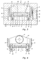
- Fig. 3
- eine Schnittdarstellung des Linearmotorsystems gemäß Linie III-III in
Fig. 5 ; - Fig. 4
- eine Schnittdarstellung des Linearmotorsystems gemäß Linie IV-IV in
Fig. 5 ; sowie - Fig. 5
- einen Längsschnitt des Linearmotorsystems gemäß Linie V-V in
Fig. 2 .
- Fig. 1
- a sectional view of a linear motor system according to the prior art;
- Fig. 2
- a linear motor system according to the invention in a three-dimensional representation;
- Fig. 3
- a sectional view of the linear motor system according to line III-III in
Fig. 5 ; - Fig. 4
- a sectional view of the linear motor system according to line IV-IV in
Fig. 5 ; such as - Fig. 5
- a longitudinal section of the linear motor system according to line VV in
Fig. 2 ,
Das in
Das in den
Für die Befestigung der Führungsschienen 3 und des Sekundärteils 4 der Antriebseinheit wird der selbe Satz Schrauben 9 verwendet, wobei die Schrauben 9 zur gleichzeitigen Befestigung der Führungsschienen 3 und des Sekundärteils 4 in Sacklochbohrungen 10 der Führungsschienen 3 befestigt sind.For fixing the
An zumindest einem der Flanschbereiche 8 ist ein Maßband 17 angeordnet, das mit einer Messkopfeinheit 16 am Motorschlitten 2 zusammenwirkt.At at least one of the
In den beiden Endbereich des Grundprofils 1 ist jeweils ein Endanschlag 20 mit einem elastischen Pufferelement 21 angeordnet, der am Basisbereich 7 (siehe
Der Sekundärteil 4 der Antriebseinheit weist eine Vielzahl streifenförmiger Magnetplatten 14 auf, die auf einer Trägerplatte 15 angeordnet, beispielsweise durch Kleben befestigt, sind, wobei die Trägerplatte 15 unter Zwischenlage des Basisbereichs 7 des Grundprofils 1 mit den Führungsschienen 3 verschraubt ist (siehe
Der Motorschlitten 2 des Linearmotorsystems besteht im Wesentlichen aus einer den Primärteil 5 aufnehmenden Motorplatte 11, die über Seitenteile 12 mit einer Schlittenplatte 13 verbunden ist, an welcher die Schlittenführungen 6 befestigt sind. Es entsteht dadurch eine nach außen abgeschlossene, kompakte Einheit, die vom Grundprofil 1 durchsetzt wird.The
In einem der Seitenteile 12 des Motorschlittens 2 kann eine Messkopfeinheit 16 integriert sein, welche mit dem Maßband 17 zusammenwirkt, das am Flanschbereiche 8 des Grundprofils 1 befestigt ist (siehe
Weiters sind in
Bei der dargestellten Ausführungsvariante ist der Motorschlitten 2 der bewegliche Teil. Es sei jedoch angemerkt, dass auch eine Invertierung des Bewegungskonzepts möglich ist und somit Anwendungen denkbar sind, bei welchen das Grundprofil 1 der bewegliche Teil des erfindungsgemäßen Linearmotorsystems ist.In the illustrated embodiment, the
Claims (10)
- A linear motor system, comprising a base profile (1) and a motor slide (2) which can be moved linearly to the base profile (1), with two separate guide rails (3) and a secondary part (4) of a drive unit being fastened to the base profile (1), and with the motor slide (2) being provided with slide guides (6) and a primary part (5) of the drive unit, with the guide rails (3) being fixed with screws (9) to one side of a base area (7) of the base profile (1), characterised in that the two guide rails (3) and the secondary part (4) are arranged on opposite sides of the base area (7) of the base profile (1), with the screws (9) on the side of the base area (7) which is opposite of the guide rails (3) fixing the secondary part (4) of the drive unit.
- A linear motor system according to claim 1, characterised in that the screws (9) are fixed in blind hole bores (10) of the guide rails (3) for the simultaneous fixing of the guide rails (3) and the secondary part (4).
- A linear motor system according to claim 1 or 2, characterised in that the base profile (1) has a substantially U-shaped cross-section with flange areas (8) protruding on both sides from the base area (7) and is preferably formed of sheet steel.
- A linear motor system according to claim 3, characterised in that a measuring tape (17) is arranged on at least one of the flange areas (8), which measuring tape cooperates with a measuring head unit (16) on the motor slide (2).
- A linear motor system according to claim 3 or 4, characterised in that a limit stop (20) is arranged in at least one end region of the base profile (1), which limit stop is fixed to the base area (7) or to the flange areas (8) of the base profile (1).
- A linear motor system according to claim 1 or 2, characterised in that the secondary part (4) of the drive unit comprises a support plate (15), on which the magnetic plates (14) of the secondary part (4) which are strip-like for example are preferably fastened by gluing, with the support plate (15) being screwed together with the guide rails (3) by interposing the base area (7) of the base profile (1).
- A linear motor system according to one of the claims 1 to 6, characterised in that the motor slide (2) comprises a motor plate (11) which accommodates the primary part (5) of the drive unit and which is connected via side parts (12) with a slide plate (13) to which the slide guides (6) are fastened.
- A linear motor system according to claim 7, characterised in that the motor plate (11), the side parts (12) and the slide plate (13) form an enclosed unit which is penetrated by the base profile (1).
- A linear motor system according to claim 7 or 8, characterised in that a measuring head unit (16) is arranged in one of the side parts (12) of the motor slide (2).
- A linear motor system according to claim 9, characterised in that the housing of the measuring head unit (16) is arranged as a supporting side part (12) of the motor slide (2).
Applications Claiming Priority (1)
| Application Number | Priority Date | Filing Date | Title |
|---|---|---|---|
| AT0141209A AT508651B1 (en) | 2009-09-08 | 2009-09-08 | LINEAR MOTOR SYSTEM |
Publications (3)
| Publication Number | Publication Date |
|---|---|
| EP2293418A2 EP2293418A2 (en) | 2011-03-09 |
| EP2293418A3 EP2293418A3 (en) | 2011-05-04 |
| EP2293418B1 true EP2293418B1 (en) | 2012-07-04 |
Family
ID=43086800
Family Applications (1)
| Application Number | Title | Priority Date | Filing Date |
|---|---|---|---|
| EP10175164A Active EP2293418B1 (en) | 2009-09-08 | 2010-09-03 | Linear motor system |
Country Status (2)
| Country | Link |
|---|---|
| EP (1) | EP2293418B1 (en) |
| AT (1) | AT508651B1 (en) |
Families Citing this family (3)
| Publication number | Priority date | Publication date | Assignee | Title |
|---|---|---|---|---|
| US20140263879A1 (en) * | 2013-03-14 | 2014-09-18 | Gilson, Inc. | Compliant bearing system with a rigid support structure |
| CN112169159A (en) * | 2020-11-04 | 2021-01-05 | 哈尔滨理工大学 | Hand-held electric particle implantation device driven by linear motor |
| CN112206406B (en) * | 2020-11-11 | 2022-09-30 | 哈尔滨理工大学 | Linear motor driven hand-held electric particle implantation gun |
Family Cites Families (8)
| Publication number | Priority date | Publication date | Assignee | Title |
|---|---|---|---|---|
| JPS5752365A (en) | 1980-09-12 | 1982-03-27 | Takahashi Yoshiteru | Linear motor |
| DE4301434C2 (en) * | 1993-01-20 | 1996-03-28 | Star Gmbh | Linear guide arrangement with compensating means for mechanical stresses |
| JP3118131B2 (en) * | 1993-12-03 | 2000-12-18 | 日本トムソン株式会社 | DC linear motor with two movable tables |
| EP1217160A3 (en) | 2000-12-22 | 2010-04-14 | Inventio Ag | Door suspension system |
| EP1752851A1 (en) | 2005-08-12 | 2007-02-14 | Schneeberger Holding AG | Linear guiding system with measuring means |
| DE102006056516A1 (en) | 2006-11-29 | 2008-06-05 | Isel Automation Gmbh & Co. Kg | linear unit |
| DE202007002504U1 (en) | 2007-02-16 | 2007-04-26 | Fischer, Peter | Electrical linear drive for use in linear motor, has base carrier that is operated together with linear guide of profile-guide rail, and two carriages that are aligned on profile-guide rail and are moved along rail |
| JP2010539878A (en) * | 2007-09-20 | 2010-12-16 | フェスト アーゲー ウント コー カーゲー | Direct drive linear electromagnetic drive device comprising a stator having two guide rails for linearly guiding the drive carriage |
-
2009
- 2009-09-08 AT AT0141209A patent/AT508651B1/en active
-
2010
- 2010-09-03 EP EP10175164A patent/EP2293418B1/en active Active
Also Published As
| Publication number | Publication date |
|---|---|
| AT508651B1 (en) | 2011-06-15 |
| EP2293418A2 (en) | 2011-03-09 |
| AT508651A1 (en) | 2011-03-15 |
| EP2293418A3 (en) | 2011-05-04 |
Similar Documents
| Publication | Publication Date | Title |
|---|---|---|
| EP2132864B1 (en) | Electrical direct linear drive device having two guide rails for the linear guidance of a stator having a driven sled | |
| DE102010010353B4 (en) | linear motor | |
| DE102020104857A1 (en) | Drive arrangement for an electric drive axle | |
| EP2293418B1 (en) | Linear motor system | |
| EP0207215A1 (en) | Slide way | |
| DE102008024909A1 (en) | Driving device for controlled displaceable carriages of machine base frame in machine tool, has fixed bearing and movable bearing, which are spaced apart from each other, for supporting shaft of electric motor | |
| WO2017140760A1 (en) | Damping of vibrations of a machine | |
| EP2221491A1 (en) | Linear movement device with interruption-free return opening | |
| EP2061136A1 (en) | Electric direct drive for a roller | |
| EP0345536B1 (en) | Linear guide | |
| EP0552647B1 (en) | Fixing device for panels, wire grilles, wire fabric or similar in frames bordered by profiled guide rails | |
| DE102017206584A1 (en) | Linear motion device with sensor holder | |
| EP3513099B1 (en) | Gearbox-side motor end shield | |
| EP2672042A2 (en) | Guide rail assembly | |
| CH699636B1 (en) | Linear motor system useful in industrial applications, comprises a base profile and a linear motor carriage movable to the base profile, where the base profile is equipped with a guide rail and a secondary part of a drive unit | |
| DE102009008882B4 (en) | Linear motor drive | |
| DE102012108635A1 (en) | Device for changing over tongue rails of switch, has electric drive fixed with control rods in active state, where control rods are connected with tongue rails, and spindle fixed with electric drive and moving along adjustable device | |
| DE202009005247U1 (en) | The linear motor system | |
| EP1756427A1 (en) | Motor/pump unit | |
| DE102006052364A1 (en) | Linear drive e.g. iron core linear drive, has component resting at surfaces, which are arranged perpendicular to each other, where one surface is arranged parallel to base surface of main guide element | |
| EP1386385B1 (en) | Linear motor comprising an integrated guide | |
| EP3330472B1 (en) | Carousel door arrangement and method for compensating for a non-uniform external force | |
| EP2149971B1 (en) | Rotating linear drive device with soft magnetic element for stabilising the rotor | |
| DE10256761B4 (en) | Rail vehicle and a floating bearing | |
| EP2072861B1 (en) | Anti-twist device with tolerance balance |
Legal Events
| Date | Code | Title | Description |
|---|---|---|---|
| PUAI | Public reference made under article 153(3) epc to a published international application that has entered the european phase |
Free format text: ORIGINAL CODE: 0009012 |
|
| AK | Designated contracting states |
Kind code of ref document: A2 Designated state(s): AL AT BE BG CH CY CZ DE DK EE ES FI FR GB GR HR HU IE IS IT LI LT LU LV MC MK MT NL NO PL PT RO SE SI SK SM TR |
|
| AX | Request for extension of the european patent |
Extension state: BA ME RS |
|
| PUAL | Search report despatched |
Free format text: ORIGINAL CODE: 0009013 |
|
| AK | Designated contracting states |
Kind code of ref document: A3 Designated state(s): AL AT BE BG CH CY CZ DE DK EE ES FI FR GB GR HR HU IE IS IT LI LT LU LV MC MK MT NL NO PL PT RO SE SI SK SM TR |
|
| AX | Request for extension of the european patent |
Extension state: BA ME RS |
|
| 17P | Request for examination filed |
Effective date: 20111104 |
|
| REG | Reference to a national code |
Ref country code: DE Ref legal event code: R079 Ref document number: 502010000977 Country of ref document: DE Free format text: PREVIOUS MAIN CLASS: H02K0007080000 Ipc: F16C0029000000 |
|
| GRAP | Despatch of communication of intention to grant a patent |
Free format text: ORIGINAL CODE: EPIDOSNIGR1 |
|
| RIC1 | Information provided on ipc code assigned before grant |
Ipc: H02K 41/02 20060101ALI20111230BHEP Ipc: H02K 41/03 20060101ALI20111230BHEP Ipc: F16C 29/00 20060101AFI20111230BHEP Ipc: H02K 7/08 20060101ALI20111230BHEP |
|
| GRAS | Grant fee paid |
Free format text: ORIGINAL CODE: EPIDOSNIGR3 |
|
| GRAA | (expected) grant |
Free format text: ORIGINAL CODE: 0009210 |
|
| AK | Designated contracting states |
Kind code of ref document: B1 Designated state(s): AL AT BE BG CH CY CZ DE DK EE ES FI FR GB GR HR HU IE IS IT LI LT LU LV MC MK MT NL NO PL PT RO SE SI SK SM TR |
|
| REG | Reference to a national code |
Ref country code: GB Ref legal event code: FG4D Free format text: NOT ENGLISH |
|
| REG | Reference to a national code |
Ref country code: CH Ref legal event code: EP Ref country code: CH Ref legal event code: NV Representative=s name: ISLER & PEDRAZZINI AG |
|
| REG | Reference to a national code |
Ref country code: AT Ref legal event code: REF Ref document number: 565291 Country of ref document: AT Kind code of ref document: T Effective date: 20120715 |
|
| REG | Reference to a national code |
Ref country code: IE Ref legal event code: FG4D Free format text: LANGUAGE OF EP DOCUMENT: GERMAN |
|
| REG | Reference to a national code |
Ref country code: DE Ref legal event code: R096 Ref document number: 502010000977 Country of ref document: DE Effective date: 20120830 |
|
| REG | Reference to a national code |
Ref country code: NL Ref legal event code: VDEP Effective date: 20120704 |
|
| PG25 | Lapsed in a contracting state [announced via postgrant information from national office to epo] |
Ref country code: SI Free format text: LAPSE BECAUSE OF FAILURE TO SUBMIT A TRANSLATION OF THE DESCRIPTION OR TO PAY THE FEE WITHIN THE PRESCRIBED TIME-LIMIT Effective date: 20120704 |
|
| REG | Reference to a national code |
Ref country code: LT Ref legal event code: MG4D Effective date: 20120704 |
|
| PG25 | Lapsed in a contracting state [announced via postgrant information from national office to epo] |
Ref country code: HR Free format text: LAPSE BECAUSE OF FAILURE TO SUBMIT A TRANSLATION OF THE DESCRIPTION OR TO PAY THE FEE WITHIN THE PRESCRIBED TIME-LIMIT Effective date: 20120704 Ref country code: NO Free format text: LAPSE BECAUSE OF FAILURE TO SUBMIT A TRANSLATION OF THE DESCRIPTION OR TO PAY THE FEE WITHIN THE PRESCRIBED TIME-LIMIT Effective date: 20121004 Ref country code: IS Free format text: LAPSE BECAUSE OF FAILURE TO SUBMIT A TRANSLATION OF THE DESCRIPTION OR TO PAY THE FEE WITHIN THE PRESCRIBED TIME-LIMIT Effective date: 20121104 Ref country code: FI Free format text: LAPSE BECAUSE OF FAILURE TO SUBMIT A TRANSLATION OF THE DESCRIPTION OR TO PAY THE FEE WITHIN THE PRESCRIBED TIME-LIMIT Effective date: 20120704 Ref country code: CY Free format text: LAPSE BECAUSE OF FAILURE TO SUBMIT A TRANSLATION OF THE DESCRIPTION OR TO PAY THE FEE WITHIN THE PRESCRIBED TIME-LIMIT Effective date: 20120704 Ref country code: LT Free format text: LAPSE BECAUSE OF FAILURE TO SUBMIT A TRANSLATION OF THE DESCRIPTION OR TO PAY THE FEE WITHIN THE PRESCRIBED TIME-LIMIT Effective date: 20120704 |
|
| PG25 | Lapsed in a contracting state [announced via postgrant information from national office to epo] |
Ref country code: SE Free format text: LAPSE BECAUSE OF FAILURE TO SUBMIT A TRANSLATION OF THE DESCRIPTION OR TO PAY THE FEE WITHIN THE PRESCRIBED TIME-LIMIT Effective date: 20120704 Ref country code: PT Free format text: LAPSE BECAUSE OF FAILURE TO SUBMIT A TRANSLATION OF THE DESCRIPTION OR TO PAY THE FEE WITHIN THE PRESCRIBED TIME-LIMIT Effective date: 20121105 Ref country code: PL Free format text: LAPSE BECAUSE OF FAILURE TO SUBMIT A TRANSLATION OF THE DESCRIPTION OR TO PAY THE FEE WITHIN THE PRESCRIBED TIME-LIMIT Effective date: 20120704 Ref country code: GR Free format text: LAPSE BECAUSE OF FAILURE TO SUBMIT A TRANSLATION OF THE DESCRIPTION OR TO PAY THE FEE WITHIN THE PRESCRIBED TIME-LIMIT Effective date: 20121005 Ref country code: LV Free format text: LAPSE BECAUSE OF FAILURE TO SUBMIT A TRANSLATION OF THE DESCRIPTION OR TO PAY THE FEE WITHIN THE PRESCRIBED TIME-LIMIT Effective date: 20120704 |
|
| PG25 | Lapsed in a contracting state [announced via postgrant information from national office to epo] |
Ref country code: NL Free format text: LAPSE BECAUSE OF FAILURE TO SUBMIT A TRANSLATION OF THE DESCRIPTION OR TO PAY THE FEE WITHIN THE PRESCRIBED TIME-LIMIT Effective date: 20120704 |
|
| BERE | Be: lapsed |
Owner name: KML LINEAR MOTION TECHNOLOGY GMBH Effective date: 20120930 |
|
| PG25 | Lapsed in a contracting state [announced via postgrant information from national office to epo] |
Ref country code: ES Free format text: LAPSE BECAUSE OF FAILURE TO SUBMIT A TRANSLATION OF THE DESCRIPTION OR TO PAY THE FEE WITHIN THE PRESCRIBED TIME-LIMIT Effective date: 20121015 Ref country code: EE Free format text: LAPSE BECAUSE OF FAILURE TO SUBMIT A TRANSLATION OF THE DESCRIPTION OR TO PAY THE FEE WITHIN THE PRESCRIBED TIME-LIMIT Effective date: 20120704 Ref country code: RO Free format text: LAPSE BECAUSE OF FAILURE TO SUBMIT A TRANSLATION OF THE DESCRIPTION OR TO PAY THE FEE WITHIN THE PRESCRIBED TIME-LIMIT Effective date: 20120704 Ref country code: DK Free format text: LAPSE BECAUSE OF FAILURE TO SUBMIT A TRANSLATION OF THE DESCRIPTION OR TO PAY THE FEE WITHIN THE PRESCRIBED TIME-LIMIT Effective date: 20120704 Ref country code: MC Free format text: LAPSE BECAUSE OF NON-PAYMENT OF DUE FEES Effective date: 20120930 Ref country code: CZ Free format text: LAPSE BECAUSE OF FAILURE TO SUBMIT A TRANSLATION OF THE DESCRIPTION OR TO PAY THE FEE WITHIN THE PRESCRIBED TIME-LIMIT Effective date: 20120704 |
|
| PLBE | No opposition filed within time limit |
Free format text: ORIGINAL CODE: 0009261 |
|
| STAA | Information on the status of an ep patent application or granted ep patent |
Free format text: STATUS: NO OPPOSITION FILED WITHIN TIME LIMIT |
|
| PG25 | Lapsed in a contracting state [announced via postgrant information from national office to epo] |
Ref country code: SK Free format text: LAPSE BECAUSE OF FAILURE TO SUBMIT A TRANSLATION OF THE DESCRIPTION OR TO PAY THE FEE WITHIN THE PRESCRIBED TIME-LIMIT Effective date: 20120704 |
|
| 26N | No opposition filed |
Effective date: 20130405 |
|
| REG | Reference to a national code |
Ref country code: IE Ref legal event code: MM4A |
|
| PG25 | Lapsed in a contracting state [announced via postgrant information from national office to epo] |
Ref country code: BE Free format text: LAPSE BECAUSE OF NON-PAYMENT OF DUE FEES Effective date: 20120930 Ref country code: BG Free format text: LAPSE BECAUSE OF FAILURE TO SUBMIT A TRANSLATION OF THE DESCRIPTION OR TO PAY THE FEE WITHIN THE PRESCRIBED TIME-LIMIT Effective date: 20121004 Ref country code: IE Free format text: LAPSE BECAUSE OF NON-PAYMENT OF DUE FEES Effective date: 20120903 |
|
| REG | Reference to a national code |
Ref country code: DE Ref legal event code: R097 Ref document number: 502010000977 Country of ref document: DE Effective date: 20130405 |
|
| PG25 | Lapsed in a contracting state [announced via postgrant information from national office to epo] |
Ref country code: AL Free format text: LAPSE BECAUSE OF FAILURE TO SUBMIT A TRANSLATION OF THE DESCRIPTION OR TO PAY THE FEE WITHIN THE PRESCRIBED TIME-LIMIT Effective date: 20120704 Ref country code: MT Free format text: LAPSE BECAUSE OF FAILURE TO SUBMIT A TRANSLATION OF THE DESCRIPTION OR TO PAY THE FEE WITHIN THE PRESCRIBED TIME-LIMIT Effective date: 20120704 |
|
| PG25 | Lapsed in a contracting state [announced via postgrant information from national office to epo] |
Ref country code: TR Free format text: LAPSE BECAUSE OF FAILURE TO SUBMIT A TRANSLATION OF THE DESCRIPTION OR TO PAY THE FEE WITHIN THE PRESCRIBED TIME-LIMIT Effective date: 20120704 |
|
| PG25 | Lapsed in a contracting state [announced via postgrant information from national office to epo] |
Ref country code: LU Free format text: LAPSE BECAUSE OF NON-PAYMENT OF DUE FEES Effective date: 20120903 Ref country code: SM Free format text: LAPSE BECAUSE OF FAILURE TO SUBMIT A TRANSLATION OF THE DESCRIPTION OR TO PAY THE FEE WITHIN THE PRESCRIBED TIME-LIMIT Effective date: 20120704 |
|
| PG25 | Lapsed in a contracting state [announced via postgrant information from national office to epo] |
Ref country code: HU Free format text: LAPSE BECAUSE OF FAILURE TO SUBMIT A TRANSLATION OF THE DESCRIPTION OR TO PAY THE FEE WITHIN THE PRESCRIBED TIME-LIMIT Effective date: 20100903 |
|
| PGFP | Annual fee paid to national office [announced via postgrant information from national office to epo] |
Ref country code: GB Payment date: 20140929 Year of fee payment: 5 |
|
| PGFP | Annual fee paid to national office [announced via postgrant information from national office to epo] |
Ref country code: IT Payment date: 20140926 Year of fee payment: 5 |
|
| PGFP | Annual fee paid to national office [announced via postgrant information from national office to epo] |
Ref country code: FR Payment date: 20140929 Year of fee payment: 5 |
|
| PG25 | Lapsed in a contracting state [announced via postgrant information from national office to epo] |
Ref country code: MK Free format text: LAPSE BECAUSE OF FAILURE TO SUBMIT A TRANSLATION OF THE DESCRIPTION OR TO PAY THE FEE WITHIN THE PRESCRIBED TIME-LIMIT Effective date: 20120704 |
|
| PG25 | Lapsed in a contracting state [announced via postgrant information from national office to epo] |
Ref country code: IT Free format text: LAPSE BECAUSE OF NON-PAYMENT OF DUE FEES Effective date: 20150903 |
|
| GBPC | Gb: european patent ceased through non-payment of renewal fee |
Effective date: 20150903 |
|
| REG | Reference to a national code |
Ref country code: FR Ref legal event code: ST Effective date: 20160531 |
|
| PG25 | Lapsed in a contracting state [announced via postgrant information from national office to epo] |
Ref country code: GB Free format text: LAPSE BECAUSE OF NON-PAYMENT OF DUE FEES Effective date: 20150903 |
|
| PG25 | Lapsed in a contracting state [announced via postgrant information from national office to epo] |
Ref country code: FR Free format text: LAPSE BECAUSE OF NON-PAYMENT OF DUE FEES Effective date: 20150930 |
|
| REG | Reference to a national code |
Ref country code: AT Ref legal event code: MM01 Ref document number: 565291 Country of ref document: AT Kind code of ref document: T Effective date: 20150903 |
|
| PG25 | Lapsed in a contracting state [announced via postgrant information from national office to epo] |
Ref country code: AT Free format text: LAPSE BECAUSE OF NON-PAYMENT OF DUE FEES Effective date: 20150903 |
|
| P01 | Opt-out of the competence of the unified patent court (upc) registered |
Effective date: 20230523 |
|
| PGFP | Annual fee paid to national office [announced via postgrant information from national office to epo] |
Ref country code: DE Payment date: 20230928 Year of fee payment: 14 |
|
| PGFP | Annual fee paid to national office [announced via postgrant information from national office to epo] |
Ref country code: CH Payment date: 20231001 Year of fee payment: 14 |