EP2293412A2 - Verfahren zum Laden eines Batteriepacks und Batteriepack - Google Patents
Verfahren zum Laden eines Batteriepacks und Batteriepack Download PDFInfo
- Publication number
- EP2293412A2 EP2293412A2 EP10175469A EP10175469A EP2293412A2 EP 2293412 A2 EP2293412 A2 EP 2293412A2 EP 10175469 A EP10175469 A EP 10175469A EP 10175469 A EP10175469 A EP 10175469A EP 2293412 A2 EP2293412 A2 EP 2293412A2
- Authority
- EP
- European Patent Office
- Prior art keywords
- battery
- charge
- current
- charge current
- voltage
- Prior art date
- Legal status (The legal status is an assumption and is not a legal conclusion. Google has not performed a legal analysis and makes no representation as to the accuracy of the status listed.)
- Granted
Links
Images

Classifications
-
- H—ELECTRICITY
- H01—ELECTRIC ELEMENTS
- H01M—PROCESSES OR MEANS, e.g. BATTERIES, FOR THE DIRECT CONVERSION OF CHEMICAL ENERGY INTO ELECTRICAL ENERGY
- H01M10/00—Secondary cells; Manufacture thereof
- H01M10/42—Methods or arrangements for servicing or maintenance of secondary cells or secondary half-cells
- H01M10/44—Methods for charging or discharging
-
- H—ELECTRICITY
- H02—GENERATION; CONVERSION OR DISTRIBUTION OF ELECTRIC POWER
- H02J—ELECTRIC POWER NETWORKS; CIRCUIT ARRANGEMENTS OR SYSTEMS FOR SUPPLYING OR DISTRIBUTING ELECTRIC POWER; SYSTEMS FOR STORING ELECTRIC ENERGY
- H02J7/00—Circuit arrangements for charging or discharging batteries or for supplying loads from batteries
- H02J7/60—Circuit arrangements for charging or discharging batteries or for supplying loads from batteries including safety or protection arrangements
-
- H—ELECTRICITY
- H01—ELECTRIC ELEMENTS
- H01M—PROCESSES OR MEANS, e.g. BATTERIES, FOR THE DIRECT CONVERSION OF CHEMICAL ENERGY INTO ELECTRICAL ENERGY
- H01M50/00—Constructional details or processes of manufacture of the non-active parts of electrochemical cells other than fuel cells, e.g. hybrid cells
- H01M50/20—Mountings; Secondary casings or frames; Racks, modules or packs; Suspension devices; Shock absorbers; Transport or carrying devices; Holders
- H01M50/204—Racks, modules or packs for multiple batteries or multiple cells
-
- H—ELECTRICITY
- H01—ELECTRIC ELEMENTS
- H01M—PROCESSES OR MEANS, e.g. BATTERIES, FOR THE DIRECT CONVERSION OF CHEMICAL ENERGY INTO ELECTRICAL ENERGY
- H01M50/00—Constructional details or processes of manufacture of the non-active parts of electrochemical cells other than fuel cells, e.g. hybrid cells
- H01M50/50—Current conducting connections for cells or batteries
- H01M50/572—Means for preventing undesired use or discharge
-
- H—ELECTRICITY
- H02—GENERATION; CONVERSION OR DISTRIBUTION OF ELECTRIC POWER
- H02J—ELECTRIC POWER NETWORKS; CIRCUIT ARRANGEMENTS OR SYSTEMS FOR SUPPLYING OR DISTRIBUTING ELECTRIC POWER; SYSTEMS FOR STORING ELECTRIC ENERGY
- H02J7/00—Circuit arrangements for charging or discharging batteries or for supplying loads from batteries
- H02J7/02—Circuit arrangements for charging or discharging batteries or for supplying loads from batteries for charging batteries from AC mains by converters
- H02J7/04—Regulation of charging current or voltage
-
- H—ELECTRICITY
- H02—GENERATION; CONVERSION OR DISTRIBUTION OF ELECTRIC POWER
- H02J—ELECTRIC POWER NETWORKS; CIRCUIT ARRANGEMENTS OR SYSTEMS FOR SUPPLYING OR DISTRIBUTING ELECTRIC POWER; SYSTEMS FOR STORING ELECTRIC ENERGY
- H02J7/00—Circuit arrangements for charging or discharging batteries or for supplying loads from batteries
- H02J7/90—Regulation of charging or discharging current or voltage
- H02J7/92—Regulation of charging or discharging current or voltage with prioritisation of loads or sources
-
- H—ELECTRICITY
- H02—GENERATION; CONVERSION OR DISTRIBUTION OF ELECTRIC POWER
- H02J—ELECTRIC POWER NETWORKS; CIRCUIT ARRANGEMENTS OR SYSTEMS FOR SUPPLYING OR DISTRIBUTING ELECTRIC POWER; SYSTEMS FOR STORING ELECTRIC ENERGY
- H02J7/00—Circuit arrangements for charging or discharging batteries or for supplying loads from batteries
- H02J7/90—Regulation of charging or discharging current or voltage
- H02J7/94—Regulation of charging or discharging current or voltage in response to battery current
-
- H—ELECTRICITY
- H02—GENERATION; CONVERSION OR DISTRIBUTION OF ELECTRIC POWER
- H02J—ELECTRIC POWER NETWORKS; CIRCUIT ARRANGEMENTS OR SYSTEMS FOR SUPPLYING OR DISTRIBUTING ELECTRIC POWER; SYSTEMS FOR STORING ELECTRIC ENERGY
- H02J7/00—Circuit arrangements for charging or discharging batteries or for supplying loads from batteries
- H02J7/90—Regulation of charging or discharging current or voltage
- H02J7/96—Regulation of charging or discharging current or voltage in response to battery voltage
-
- H—ELECTRICITY
- H02—GENERATION; CONVERSION OR DISTRIBUTION OF ELECTRIC POWER
- H02J—ELECTRIC POWER NETWORKS; CIRCUIT ARRANGEMENTS OR SYSTEMS FOR SUPPLYING OR DISTRIBUTING ELECTRIC POWER; SYSTEMS FOR STORING ELECTRIC ENERGY
- H02J7/00—Circuit arrangements for charging or discharging batteries or for supplying loads from batteries
- H02J7/60—Circuit arrangements for charging or discharging batteries or for supplying loads from batteries including safety or protection arrangements
- H02J7/61—Circuit arrangements for charging or discharging batteries or for supplying loads from batteries including safety or protection arrangements against overcharge
-
- H—ELECTRICITY
- H02—GENERATION; CONVERSION OR DISTRIBUTION OF ELECTRIC POWER
- H02J—ELECTRIC POWER NETWORKS; CIRCUIT ARRANGEMENTS OR SYSTEMS FOR SUPPLYING OR DISTRIBUTING ELECTRIC POWER; SYSTEMS FOR STORING ELECTRIC ENERGY
- H02J7/00—Circuit arrangements for charging or discharging batteries or for supplying loads from batteries
- H02J7/60—Circuit arrangements for charging or discharging batteries or for supplying loads from batteries including safety or protection arrangements
- H02J7/63—Circuit arrangements for charging or discharging batteries or for supplying loads from batteries including safety or protection arrangements against overdischarge
-
- Y—GENERAL TAGGING OF NEW TECHNOLOGICAL DEVELOPMENTS; GENERAL TAGGING OF CROSS-SECTIONAL TECHNOLOGIES SPANNING OVER SEVERAL SECTIONS OF THE IPC; TECHNICAL SUBJECTS COVERED BY FORMER USPC CROSS-REFERENCE ART COLLECTIONS [XRACs] AND DIGESTS
- Y02—TECHNOLOGIES OR APPLICATIONS FOR MITIGATION OR ADAPTATION AGAINST CLIMATE CHANGE
- Y02E—REDUCTION OF GREENHOUSE GAS [GHG] EMISSIONS, RELATED TO ENERGY GENERATION, TRANSMISSION OR DISTRIBUTION
- Y02E60/00—Enabling technologies; Technologies with a potential or indirect contribution to GHG emissions mitigation
- Y02E60/10—Energy storage using batteries
Definitions
- aspects of the present invention relate to a method of charging a battery pack and the battery pack.
- Such a secondary battery is configured as a battery pack including a battery cell and a charge/discharge circuit.
- the battery cell is charged or discharged by an external power source or load through an external terminal installed in the battery pack. That is, when the external power source is connected to the battery pack through the external terminal, the battery cell is charged by an external power supplied through the external terminal and the charge/discharge circuit.
- the charge/discharge circuit is disposed between the external terminal and the battery cell to control a charging/discharging operation of the battery cell.
- the battery cell is charged at maximal charging current until a power of the battery cell reaches a certain voltage. Then, when the power of the battery cell reaches the certain voltage, the charge current gradually decreases.
- aspects of the present invention provide a method of charging a battery pack preventing a battery and/or an external power source from being damaged due to a trickle charge current in order to improve the safety of the battery, and to improve the battery itself.
- aspects of the present invention provide a method of charging a battery pack, the method including: determining whether a charge current exists; determining whether the charge current and a charge voltage are changed if determined that the charge current exists; determining whether the charge current is changed from a first current level to a second current level less than the first current level, and a present voltage level of the battery is less than a former voltage level if determined that the charge current and the charge voltage are changed; and maintaining the charge current at the second current level for a predetermined maintenance time if determined that the present voltage level of the battery is less than the former voltage level.
- the determining of whether the charge current exists may include determining that the charge current exists if the charge current is detected for a predetermined detection time.
- the predetermined detection time may range from about 0.5 seconds to about 2 seconds.
- the determining of whether the charge current exists may include recognizing that the battery is in a self discharge mode if the charge current does not exist.
- the predetermined maintenance time may range from about 0.5 seconds to about 2 seconds.
- the determining of whether the charge current and the charge voltage are changed may include determining that the charge current and the charge voltage are changed if a charge control signal changing both the charge current and the charge voltage is received from an external system controlling the charging of the battery.
- the maintaining of the charge current at the second current level for the predetermined maintenance time may include generating a changed charge current maintenance signal maintaining the charge current at the second current level for the predetermined maintenance time and transmitting the changed charge current maintenance signal to an external system controlling the charging of the battery.
- the battery may be charged according to a charging operation type in which the charge current is reduced sequentially if the charge voltage is increased by an external system.
- the charge current may be reduced in tiers.
- a battery pack including: a battery including at least one battery cell, the battery being connected to an external terminal through a high current path; a protective circuit connected in parallel to the battery and the external terminal, the protective circuit detecting a voltage of the battery; and a controller connected in series between the protective circuit and the external terminal in order to receive a voltage level of the battery from the protective circuit, the controller communicating with an external system through the external terminal, wherein if the controller determines that a charge current exists in the battery, and if the controller determines that the charge current and a charge voltage are changed, and if the controller determines that the charge current of the battery is changed from a first current level to a second current level less than the first current level, and if the controller determines that the present voltage level is less than the former voltage level, then the controller generates a changed charge current maintenance signal maintaining the charge current at the second current level for a predetermined maintenance time.
- the battery pack may further include a sensor resistor disposed on the high current path, the sensor resistor being connected to the controller, wherein the controller determines that the charge current exists in the battery if the charge current of the battery is detected in the sensor resistor for a predetermined detection time.
- the predetermined detection time may range from about 0.5 seconds to about 2 seconds.
- the controller may recognize that that the battery is in a self discharge mode, generate a self discharge mode signal, and transmits the self discharge mode signal to the external system.
- the predetermined maintenance time may range from about 0.5 seconds to about 2 seconds.
- the controller determines that the charge current and the charge voltage are changed if a charge control signal changing the charge current and the charge voltage is received from the external system controlling the charging of the battery.
- the controller may transmit the changed charge current maintenance signal to the external system controlling the charging of the battery.
- the battery pack may further include an SMBUS between the controller and the external terminal, the SMBUS allowing the controller and the external system to communicate with each other.
- the battery may be charged according to a charging operation type wherein the charge current is reduced sequentially if the charge voltage is increased by the external system.
- the charge current may be reduced in tiers.
- the elements may be “directly connected” to each other or “electrically connected” to each other with another device being interposed therebetween.
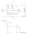
- FIG. 1 illustrates a circuit diagram of a configuration of a battery pack according to an embodiment of the present invention
- FIG. 2 illustrates a graph of a charging manner of an external power source for charging a battery pack.
- a battery pack 100 includes a battery 110, an external terminal 120, a charge device 130, a discharge device 140, a sensor resistor 150, a protective circuit 160, a controller 170, and an SMBUS 180.
- the battery pack 100 is connected to an external power source or an external load of an external system 200 through the external terminal 120 to perform a charging operation or a discharging operation.
- a high current path (HCP) between the external terminal 120 and the battery 110 is used as a charge/discharge path.
- a relatively large current flows through the high current path HCP.
- the battery pack 100 may communicate with the external system 200 through the SMBUS 180.
- the external system 200 may include an external power source such as an adapter (not shown) for supplying a power into portable electrical devices, e.g., portable notebook computers or other similar portable electrical devices.
- the battery 110 may be charged by the external power source of the external system 200. When the external system 200 is separated from the external power source, a power of the battery 110 is supplied to the external load of the external system 200 through the external terminal 120 to discharge the battery 110.
- the battery 110 may include at least one of battery cells B1, B2, and B3.
- the battery 110 may be charged or discharged at a constant voltage.
- reference symbols B+ and B- indicate high current ends and represent a positive power source and a negative power source of the battery cells B1, B2, and B3 connected to each other in series, respectively.
- three battery cells B1, B2, B3 are connected to each other in series to form the battery 110, the number of battery cells may be varied according to a capacity need for the external system.
- the external terminal 120 is connected in parallel to the battery 110. Also, the external terminal 120 is connected to the external power source or the external load to charge or discharge the battery the battery 110.
- reference symbol P+ represents a positive terminal connected to the positive power source B+ of the battery 110
- reference symbol P- represents a negative terminal connected to the negative power source B- of the battery 110.
- the battery pack 100 is connected to the external power source or the external load of the external system 200 through the external terminal 120. That is, when the external system 200 connected to the external power source is connected to the external terminal 120, the battery 110 is charged by the external power source. Also, when the external load of the external system 200 is connected to the external terminal 120, the battery 110 is discharged by the external load.
- the charge device 130 and the discharge device 140 are connected to each other in series on the high current path HCP between the battery 110 and the external terminal 120 to perform the charging or discharging operation.
- Each of the charge device 130 and the discharge device 140 includes a field effect transistor (FET) and a parasitic diode (D). That is, the charge device 130 includes the FET1 and D1, and the discharge device 140 includes FET2 and D2.
- FET field effect transistor
- D parasitic diode
- a connection direction between a source and a drain of the FET1 of the charge device 130 is opposite to that of the FET2 of the discharge device 140.
- the FET1 of the charge device 130 restricts a current flow from the external terminal 120 to the battery 110
- the FET2 of the discharge device 140 restricts a current flow from the battery 110 to the external terminal 120
- the FET1 and FET2 of the charge and discharge devices 130 and 140 may include switching devices, respectively. However, other types of electrical devices performing a switching function may be used.
- the D1 and D2 of the charge and discharge devices 130 and 140 are configured to allow a current to flow in a direction opposite to that in which the current flow is restricted.
- the sensor resistor 150 is connected in series on the high current path HCP between the battery 110 and the external terminal 120. Both ends of the sensor resistor 150 are connected to the protective circuit 160 or the controller 170. As a result, the sensor resistor 150 allows the protective circuit 160 or the controller 170 to confirm voltage values at both ends of the sensor resistor 150 and a resistance value of the sensor resistor 150. Thus, the sensor resistor 150 transmits data with respect to a charge current or a discharge current of the battery 110 to the protective circuit 160 or the controller 170.
- the protective circuit 160 is connected in parallel between the battery 110 and the charge and discharge devices 130 and 140.
- the protective circuit 160 is connected in series between the battery 110 and the controller 170.
- the protective circuit 160 detects a voltage of the battery 110 to transmit the detected voltage to the controller 170.
- the protective circuit 160 operates the charge device 130 and the discharge device 140 under the control of the controller 170.
- the protective circuit 160 may be realized by a protective circuit IC (integrated circuit) or an analog front end (AFE) IC. However, other similar circuits may be used.
- the protective circuit 160 sets the FET1 of the charge device 130 to be in an ON state and sets the FET2 of the discharge device 140 to be in an ON state in order to charge the battery 110.
- the protective circuit 160 sets the FET1 of the charge device 130 to be in an ON state and the FET2 of the discharge device 140 to be in an ON state under the control of the controller 170 in order to discharge the battery 110.
- the protective circuit 160 may detect voltages of each of the battery cells B1, B2, and B3.
- the controller 170 includes an integrated circuit (IC) connected in series between the protective circuit 160 and the external terminal 120.
- the controller 170 stores a voltage level of the battery 110 received through the protective circuit 160 in order to compare the stored voltage level to a preset voltage level.
- the controller 170 outputs a control signal according to the comparison result in order to turn ON/OFF the charge device 130 and the discharge device 140.
- a voltage level of the battery 110 received by the controller 170 is greater than a preset overcharge voltage level, e.g., about 4.35 V
- the controller 170 determines that the battery 110 is in an overcharge state and outputs a control signal corresponding to the overcharge state, thereby turning off the FET1 of the charge device 130.
- the charging operation charging the battery 110 from the external power source of the external system 200 is interrupted.
- the D1 of the charge device 130 allows the battery pack to be discharged even if the FET 1 of the charge device 130 is turned off.
- a voltage level of the battery 110 received by the controller 170 is less than a preset overdischarge voltage level, e.g., about 2.30 V
- the controller 170 determines that the battery 110 is in an overdischarge state and outputs a control signal corresponding to the overdischarge state, thereby turning off the FET2 of the discharge device 140.
- the discharging operation discharging the battery 110 with the external load of the external system 200 is interrupted.
- the D2 of the discharge device 140 allows the battery pack to be charged even if the FET 2 of the discharge device 140 is turned off.
- the controller 170 communicates with the external system 200 through the SMBUS 180 with respect to the charging/discharging operation. That is, the controller 170 receives data, such as a voltage level of the battery 110, through the protective circuit 160 in order to transmit the received data to the external system 200. Thus, the controller 170 allows the external power source of the external system 200 to confirm the data such as the voltage level of the battery 110 in order to control the charging operation of the battery 110.
- the external power source of the external system 200 controls the charging operation of the battery 110 to be a multi-step current charging operation type , wherein a charge current is reduced sequentially, e.g., in tiers according to a charge voltage increasing, as shown in FIG. 2 .
- the external power source of the external system 200 determines that the voltage level of the battery 110 received from the controller 170 is less than a charge voltage V1
- the external power source of the external system 200 controls the battery 110 to charge the battery 110 at a charge current I1 if the charge voltage is in the range of V1 to V2.
- the voltage of the battery 110 may increase up to the charge voltage V2.
- the external power source of the external system 200 confirms that the voltage level of the battery 110 received from the controller 170 increases up to the charge voltage V2
- the external power source of the external system 200 controls the battery 110 to charge the battery 110 at a charge current I2 if the charge voltage is in the range of V2 to V3.
- the voltage of the battery 110 may increase up to the charge voltage V3.
- the external power source of the external system 200 confirms that the voltage level of the battery 110 received from the controller 170 increases up to the charge voltage V3
- the external power source of the external system 200 controls the battery 110 to charge the battery 110 at a charge current I3 if the charge voltage is in the range of V3 to V4.
- the voltage of the battery 110 may increase up to the charge voltage V4.
- the charge voltage V4 may be a maximum charge voltage limiting the charging operation of the battery 110.
- the controller 170 determines that the charge current of the battery 110 is changed from a first current level to a second current level less than the first current level, and the present current of the battery 110 is less than the former current at a point in time at which the charge current exists and the charge current and the charge voltage are both changed, then the controller 170 generates a changed charge current maintenance signal.
- the changed charge current maintenance signal maintains the charge current of the battery 110 at the second current level for a predetermined maintenance time in order to prevent the charge current of the battery 110 from again increasing to the first current level.
- the controller 170 transmits the changed charge current maintenance signal to the external power source of the external system 200.
- the external power source of the external system 200 controls the charging operation of the battery 110 in order to maintain the charge current of the battery 110 at the second current level for the predetermined maintenance time.
- the predetermined maintenance time ranges from about 0.5 seconds to about 2 seconds. If the predetermined maintenance time is less than about 0.5 seconds, a charge time of the battery 110 is too short. Also, if the predetermined maintenance time is greater than about 2 seconds, a charge time of the battery 110 is too long.
- the trickle charge current may occur.
- the controller 170 determines a condition wherein the charge current exists in the battery 110, or in other words, the controller 170 determines if the battery 110 is being charged. The controller 170 determines that the charge current exists if the charge current flowing through the sensor resistor 150 is detected for a predetermined detection time. On the other hand, when the charge current flowing through the sensor resistor 150 is not detected for the predetermined detection time, the controller 170 determines that the battery 110 is in a self discharge mode and generates a self discharge mode signal to transmit the self discharge mode signal to the external system 200.
- the predetermined detection time ranges from about 0.5 seconds to about 2 seconds.
- the controller 170 may misjudge the charge current of the battery 110 as a noise or an electrostatic discharge (ESD) when the predetermined detection time is less than about 0.5 seconds. Also, when the predetermined detection time is greater than about 2 seconds, the charge current detection time may be wasted.
- ESD electrostatic discharge
- the controller 170 determines whether the charge current and the charge voltage are both changed. For example, if the controller 170 receives a charge control signal changing the charge voltage from V1 to V2, and the charge current is changed from I1 to I2, the controller 170 determines that the charge current and the charge voltage are both changed. Then, if the controller 170 confirms that the charge current is changed from the first current level (e.g., I1) to the second current level (e.g., I2) less than the first current level, and a present voltage level of the battery 110 is less than the former voltage level, the controller 170 determines that the trickle charge current occurs.
- the first current level e.g., I1
- the second current level e.g., I2
- the controller 170 determines a condition wherein the trickle charge current occurs and controls the charging operation of the battery 110, thereby preventing the trickle charge current from occurring during the charging of the battery 110.
- the SMBUS 180 is disposed between the controller 170 and the external terminal 120 so that the controller 170 and the external system 200 communicate with each other.
- the SMBUS 180 includes a clock terminal CLOCK and a data terminal DATA.
- the battery pack 100 includes the controller 170 controlling the charging operation of the battery 110 in order to maintain the charging of the battery 110 at the second current level for a predetermined maintenance time.
- the charge current is prevented from again increasing to the first current level when the charge current is changed from the first current level to the second current level less than the first current level, and the present voltage level of the battery 110 is less than the former voltage level at the point in time at which the charge current and the charge voltage are both changed during the charging of the battery 110. Therefore, the trickle charge current is prevented from occurring.
- the battery pack 100 prevents the battery 110 and/or the external power source from being damaged by the trickle charge current and improves the safety of the battery 110.
- FIG. 3 illustrates a flowchart of a charging method of the battery pack of FIG. 1 .
- a method of charging the battery pack 100 includes operation S1 to determine whether a charge current exists, operation S2 to recognize a self discharge mode, operation S2 to determine a change in a charge current and charge voltage, operation S4 to determine a battery voltage reduction, and operation S5 to maintain a changed charge current.
- the battery 110 is charged according to the multi-step current charging operation type in which the charge current is reduced sequentially according to the charge voltage increasing.
- the controller 170 determines whether the charge current exists in the battery 110, or in other words, whether the battery 110 is being charged.
- the controller 170 detects the voltages at both ends of the sensor resistor 150 in order to detect the charge current. If the charge current is detected for the predetermined detection time, the controller 170 determines that the charge current exists.
- the predetermined detection time ranges from about 0.5 seconds to about 2 seconds. However, the predetermined detection time may vary.
- the controller 170 determines that the charge current does not exist in the battery 110, or in other words, the controller 170 does not detect the voltages at both ends of the sensor resistor 150 or the controller 170 detect the voltages of both ends of the sensor resistor 150 for a time less than the predetermined detection time in operation S1, the controller 170 recognizes that the battery 110 is in a self discharge mode. The controller 170 then generates a self discharge mode signal and transmits the self discharge mode signal to the external power source of the external system 200 in operation S2.
- the controller 170 determines whether the charge current and the charge voltage are changed in operation S3. When the charge current supplied from the external power source of the external system 200 is changed, and the charge control signal changing the charge voltage is received, the controller 170 determines that the charge current and the charge voltage are both changed.
- the controller 170 determines whether the charge current is changed from the first current level to the second current level less than the first current level, and determines whether the present voltage level of the battery 110 is less than the former voltage level in operation S4.
- the controller 170 determines whether the charge current is changed from the first current level to the second current level less than the first current level, and determines whether the present voltage level of the battery 110 is less than the former voltage level in operation S4.
- the controller 170 determines that the charge current of the battery 110 is changed from the first current level to the second current level less than the first current level, and if the controller 170 determines that the present voltage level of the battery 110 is less than the former voltage level in operation S4, the controller 170 generates the changed charge current maintenance signal.
- the changed charge current maintenance signal is transmitted to the external power source of the external system 200 in order to maintain the charge current of the battery 110 at the second current level for the predetermined maintenance time in operation S5. Then, the external power source of the external system 200 controls the charging operation of the battery 110 in order to maintain the charge current of the battery 110 at the second current level for the predetermined maintenance time.
- the predetermined maintenance time ranges from about 0.5 seconds to about 2 seconds. However, the predetermined maintenance time may vary.
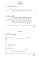
- FIG. 4A illustrates a graph of a state wherein a trickle charge current occurs and the a multi-step current charging method of the battery pack of FIG. 3 is not applied
- FIG. 4B illustrates a graph of a state wherein the trickle charge current does not occur and the multi-step charging method of the battery pack of FIG. 3 is applied.
- Horizontal axes of FIGS. 4A and 4B represent a time
- vertical axes of FIGS. 4A and 4B represent a battery voltage and a charge current.
- the battery is charged at a certain charge current until the battery voltage reaches a certain voltage. Then, after the battery voltage reaches the certain voltage, as the charge current decreases, the battery voltage decreases. Thereafter, the charge current increases again. That is, the trickle charge current occurs repeatedly. In this case, the battery or the external power source is damaged and safety of the battery decreases.
- the multi-step current charging method is applied and the charge current is maintained for the predetermined maintenance time if the charge current decreases.
- the charge current is maintained for the predetermined maintenance time so that the charge current decreases.
- the charge current is prevented from increasing again, or in other words, the trickle charge current is prevented from occurring repeatedly. In this case, damage to the battery and/or the external power source is prevented, and safety is improved.
- the charging operation of the battery may be controlled such that the charge current of the battery is maintained at the decreased current level.
- the charge current is prevented from increasing again.
- the trickle charge current is prevented from occurring repeatedly if the charge current of the battery decreases in order to decrease the battery voltage.
- the method of charging the battery pack prevents the battery and the external power source from being damaged due to the trickle charge current, and thus, safety is improved.
Landscapes
- Engineering & Computer Science (AREA)
- Power Engineering (AREA)
- Chemical & Material Sciences (AREA)
- Chemical Kinetics & Catalysis (AREA)
- Electrochemistry (AREA)
- General Chemical & Material Sciences (AREA)
- Manufacturing & Machinery (AREA)
- Charge And Discharge Circuits For Batteries Or The Like (AREA)
- Secondary Cells (AREA)
Applications Claiming Priority (1)
| Application Number | Priority Date | Filing Date | Title |
|---|---|---|---|
| KR1020090084430A KR101036085B1 (ko) | 2009-09-08 | 2009-09-08 | 배터리 팩의 충전 방법 및 배터리 팩 |
Publications (3)
| Publication Number | Publication Date |
|---|---|
| EP2293412A2 true EP2293412A2 (de) | 2011-03-09 |
| EP2293412A3 EP2293412A3 (de) | 2014-05-28 |
| EP2293412B1 EP2293412B1 (de) | 2019-03-27 |
Family
ID=43302488
Family Applications (1)
| Application Number | Title | Priority Date | Filing Date |
|---|---|---|---|
| EP10175469.5A Active EP2293412B1 (de) | 2009-09-08 | 2010-09-06 | Verfahren zum Laden eines Batteriepacks und Batteriepack |
Country Status (5)
| Country | Link |
|---|---|
| US (1) | US8686690B2 (de) |
| EP (1) | EP2293412B1 (de) |
| JP (1) | JP5181311B2 (de) |
| KR (1) | KR101036085B1 (de) |
| CN (1) | CN102013531B (de) |
Cited By (1)
| Publication number | Priority date | Publication date | Assignee | Title |
|---|---|---|---|---|
| CN104638722A (zh) * | 2015-02-02 | 2015-05-20 | 成都芯源系统有限公司 | 基于数字控制的电池充电系统及其控制电路 |
Families Citing this family (8)
| Publication number | Priority date | Publication date | Assignee | Title |
|---|---|---|---|---|
| MY169836A (en) | 2011-12-06 | 2019-05-16 | Intel Corp | Techniques for serial interface charging |
| EP2641783B1 (de) * | 2012-03-20 | 2016-04-20 | Samsung SDI Co., Ltd. | Batteriepack und Verfahren zu dessen Steuerung |
| US9153974B2 (en) * | 2012-06-13 | 2015-10-06 | GM Global Technology Operations LLC | Battery parallel balancing circuit |
| US9112361B2 (en) * | 2013-02-28 | 2015-08-18 | Brooke Schumm, Jr. | Combination and modified electrolyte to reduce risk of premature lithium ion battery failure, including in aircraft applications |
| US9929582B2 (en) * | 2014-12-23 | 2018-03-27 | Intel Corporation | Adaptive charge current for a battery |
| CN107872087B (zh) * | 2017-12-04 | 2021-01-26 | 努比亚技术有限公司 | 充电电路及充电方法 |
| TWI836705B (zh) * | 2022-11-07 | 2024-03-21 | 和碩聯合科技股份有限公司 | 電源系統 |
| TWI898263B (zh) * | 2023-09-19 | 2025-09-21 | 宏碁股份有限公司 | 電子裝置及其操作方法 |
Family Cites Families (12)
| Publication number | Priority date | Publication date | Assignee | Title |
|---|---|---|---|---|
| AT406719B (de) * | 1991-06-05 | 2000-08-25 | Enstore Forschungs Entwicklung | Verfahren zum vorzugsweisen schnellen laden von batterien |
| JP3306325B2 (ja) | 1996-12-05 | 2002-07-24 | 株式会社岡村研究所 | 並列モニタを小電力化する充電制御装置 |
| JP3403309B2 (ja) | 1997-01-31 | 2003-05-06 | 株式会社ケンウッド | 充電装置 |
| US5994878A (en) * | 1997-09-30 | 1999-11-30 | Chartec Laboratories A/S | Method and apparatus for charging a rechargeable battery |
| KR20000019006A (ko) * | 1998-09-08 | 2000-04-06 | 구자홍 | 리튬 이온 전지의 충전 방법 |
| JP2001245438A (ja) * | 2000-02-29 | 2001-09-07 | Matsushita Electric Works Ltd | 充電器 |
| CN101416330A (zh) * | 2003-10-14 | 2009-04-22 | 布莱克和戴克公司 | 二次电池的保护方法、保护电路和保护器件、电动工具、充电器和适合在电池组中提供保护以防故障状况的电池组 |
| JP2007520180A (ja) * | 2003-10-14 | 2007-07-19 | ブラック アンド デッカー インク | 電池パックの障害状態からの保護を提供するべく適合された二次電池、電動工具、充電器、及び電池パック用の保護方法、保護回路、及び保護装置 |
| KR100536216B1 (ko) | 2003-10-29 | 2005-12-12 | 삼성에스디아이 주식회사 | 배터리 팩의 충전 방법 |
| JP2007215309A (ja) * | 2006-02-08 | 2007-08-23 | Sanyo Electric Co Ltd | パック電池の制御方法 |
| US7535201B2 (en) * | 2006-10-05 | 2009-05-19 | Densei-Lambda Kabushiki Kaisha | Uninterruptible power supply system |
| JP2008206259A (ja) * | 2007-02-19 | 2008-09-04 | Matsushita Electric Ind Co Ltd | 充電システム、充電装置、及び電池パック |
-
2009
- 2009-09-08 KR KR1020090084430A patent/KR101036085B1/ko active Active
-
2010
- 2010-07-07 JP JP2010154614A patent/JP5181311B2/ja active Active
- 2010-08-25 US US12/868,655 patent/US8686690B2/en active Active
- 2010-09-06 EP EP10175469.5A patent/EP2293412B1/de active Active
- 2010-09-06 CN CN201010272486.6A patent/CN102013531B/zh active Active
Non-Patent Citations (1)
| Title |
|---|
| None |
Cited By (2)
| Publication number | Priority date | Publication date | Assignee | Title |
|---|---|---|---|---|
| CN104638722A (zh) * | 2015-02-02 | 2015-05-20 | 成都芯源系统有限公司 | 基于数字控制的电池充电系统及其控制电路 |
| CN104638722B (zh) * | 2015-02-02 | 2017-07-28 | 成都芯源系统有限公司 | 基于数字控制的电池充电系统及其控制电路 |
Also Published As
| Publication number | Publication date |
|---|---|
| KR20110026675A (ko) | 2011-03-16 |
| JP2011062071A (ja) | 2011-03-24 |
| CN102013531A (zh) | 2011-04-13 |
| KR101036085B1 (ko) | 2011-05-23 |
| US8686690B2 (en) | 2014-04-01 |
| CN102013531B (zh) | 2014-09-17 |
| EP2293412A3 (de) | 2014-05-28 |
| EP2293412B1 (de) | 2019-03-27 |
| JP5181311B2 (ja) | 2013-04-10 |
| US20110057621A1 (en) | 2011-03-10 |
Similar Documents
| Publication | Publication Date | Title |
|---|---|---|
| EP2293412B1 (de) | Verfahren zum Laden eines Batteriepacks und Batteriepack | |
| KR101093928B1 (ko) | 배터리 셀의 고온 스웰링을 방지할 수 있는 배터리 팩 및 그 방법 | |
| CN102326313B (zh) | 充电控制电路、电池组件以及充电系统 | |
| US9484763B2 (en) | Battery pack and method of controlling the same | |
| KR102101315B1 (ko) | 보호 기능 부착 충전 제어 장치 및 전지팩 | |
| US8203309B2 (en) | Battery pack, and battery system | |
| KR101182890B1 (ko) | 배터리 팩 충전 제어 시스템 | |
| JP5363740B2 (ja) | 充電制御回路、電池パック、及び充電システム | |
| US7902794B2 (en) | Over-voltage protected battery charger with bypass | |
| US8421417B2 (en) | Secondary battery control circuit | |
| KR101097248B1 (ko) | 배터리 팩 보호회로, 배터리 팩 보호방법, 및 전기 자전거 | |
| US9077196B2 (en) | Battery pack and power generation circuit in battery pack | |
| US8896270B2 (en) | Semiconductor integrated circuit, protection circuit, and battery pack | |
| US20110304299A1 (en) | System of charging battery pack and method thereof | |
| EP2216872A2 (de) | Ladungs- und Entladungssystem für eine Sekundärbatterie und Verfahren zur Steuerung der Ladung und Entladung der Sekundärbatterie | |
| JP2009133676A (ja) | 電池パックおよび充放電方法 | |
| US8937461B2 (en) | System for controlling charging of battery and battery pack comprising the same | |
| US20140055095A1 (en) | Battery pack and method of controlling the same | |
| JP2009189131A (ja) | 充電制御回路、電池パック、及び充電システム | |
| EP3993263A1 (de) | Vorrichtung und verfahren zur fet-steuerung | |
| EP2221940B1 (de) | Selbstentladende Schaltung für Sekundärbatterie und Sekundärbatterie damit | |
| KR20070109084A (ko) | 배터리 팩 | |
| US20250192593A1 (en) | Battery pack group and driving method thereof |
Legal Events
| Date | Code | Title | Description |
|---|---|---|---|
| PUAI | Public reference made under article 153(3) epc to a published international application that has entered the european phase |
Free format text: ORIGINAL CODE: 0009012 |
|
| 17P | Request for examination filed |
Effective date: 20100906 |
|
| AK | Designated contracting states |
Kind code of ref document: A2 Designated state(s): AL AT BE BG CH CY CZ DE DK EE ES FI FR GB GR HR HU IE IS IT LI LT LU LV MC MK MT NL NO PL PT RO SE SI SK SM TR |
|
| AX | Request for extension of the european patent |
Extension state: BA ME RS |
|
| PUAL | Search report despatched |
Free format text: ORIGINAL CODE: 0009013 |
|
| RIC1 | Information provided on ipc code assigned before grant |
Ipc: H02J 7/00 20060101AFI20140417BHEP |
|
| AK | Designated contracting states |
Kind code of ref document: A3 Designated state(s): AL AT BE BG CH CY CZ DE DK EE ES FI FR GB GR HR HU IE IS IT LI LT LU LV MC MK MT NL NO PL PT RO SE SI SK SM TR |
|
| AX | Request for extension of the european patent |
Extension state: BA ME RS |
|
| GRAP | Despatch of communication of intention to grant a patent |
Free format text: ORIGINAL CODE: EPIDOSNIGR1 |
|
| STAA | Information on the status of an ep patent application or granted ep patent |
Free format text: STATUS: GRANT OF PATENT IS INTENDED |
|
| INTG | Intention to grant announced |
Effective date: 20181127 |
|
| GRAS | Grant fee paid |
Free format text: ORIGINAL CODE: EPIDOSNIGR3 |
|
| GRAA | (expected) grant |
Free format text: ORIGINAL CODE: 0009210 |
|
| STAA | Information on the status of an ep patent application or granted ep patent |
Free format text: STATUS: THE PATENT HAS BEEN GRANTED |
|
| AK | Designated contracting states |
Kind code of ref document: B1 Designated state(s): AL AT BE BG CH CY CZ DE DK EE ES FI FR GB GR HR HU IE IS IT LI LT LU LV MC MK MT NL NO PL PT RO SE SI SK SM TR |
|
| REG | Reference to a national code |
Ref country code: GB Ref legal event code: FG4D |
|
| REG | Reference to a national code |
Ref country code: CH Ref legal event code: EP |
|
| REG | Reference to a national code |
Ref country code: AT Ref legal event code: REF Ref document number: 1114185 Country of ref document: AT Kind code of ref document: T Effective date: 20190415 |
|
| REG | Reference to a national code |
Ref country code: IE Ref legal event code: FG4D |
|
| REG | Reference to a national code |
Ref country code: DE Ref legal event code: R096 Ref document number: 602010057789 Country of ref document: DE |
|
| PG25 | Lapsed in a contracting state [announced via postgrant information from national office to epo] |
Ref country code: FI Free format text: LAPSE BECAUSE OF FAILURE TO SUBMIT A TRANSLATION OF THE DESCRIPTION OR TO PAY THE FEE WITHIN THE PRESCRIBED TIME-LIMIT Effective date: 20190327 Ref country code: NO Free format text: LAPSE BECAUSE OF FAILURE TO SUBMIT A TRANSLATION OF THE DESCRIPTION OR TO PAY THE FEE WITHIN THE PRESCRIBED TIME-LIMIT Effective date: 20190627 Ref country code: SE Free format text: LAPSE BECAUSE OF FAILURE TO SUBMIT A TRANSLATION OF THE DESCRIPTION OR TO PAY THE FEE WITHIN THE PRESCRIBED TIME-LIMIT Effective date: 20190327 Ref country code: LT Free format text: LAPSE BECAUSE OF FAILURE TO SUBMIT A TRANSLATION OF THE DESCRIPTION OR TO PAY THE FEE WITHIN THE PRESCRIBED TIME-LIMIT Effective date: 20190327 |
|
| REG | Reference to a national code |
Ref country code: NL Ref legal event code: MP Effective date: 20190327 |
|
| PG25 | Lapsed in a contracting state [announced via postgrant information from national office to epo] |
Ref country code: HR Free format text: LAPSE BECAUSE OF FAILURE TO SUBMIT A TRANSLATION OF THE DESCRIPTION OR TO PAY THE FEE WITHIN THE PRESCRIBED TIME-LIMIT Effective date: 20190327 Ref country code: NL Free format text: LAPSE BECAUSE OF FAILURE TO SUBMIT A TRANSLATION OF THE DESCRIPTION OR TO PAY THE FEE WITHIN THE PRESCRIBED TIME-LIMIT Effective date: 20190327 Ref country code: GR Free format text: LAPSE BECAUSE OF FAILURE TO SUBMIT A TRANSLATION OF THE DESCRIPTION OR TO PAY THE FEE WITHIN THE PRESCRIBED TIME-LIMIT Effective date: 20190628 Ref country code: BG Free format text: LAPSE BECAUSE OF FAILURE TO SUBMIT A TRANSLATION OF THE DESCRIPTION OR TO PAY THE FEE WITHIN THE PRESCRIBED TIME-LIMIT Effective date: 20190627 Ref country code: LV Free format text: LAPSE BECAUSE OF FAILURE TO SUBMIT A TRANSLATION OF THE DESCRIPTION OR TO PAY THE FEE WITHIN THE PRESCRIBED TIME-LIMIT Effective date: 20190327 |
|
| REG | Reference to a national code |
Ref country code: AT Ref legal event code: MK05 Ref document number: 1114185 Country of ref document: AT Kind code of ref document: T Effective date: 20190327 |
|
| PG25 | Lapsed in a contracting state [announced via postgrant information from national office to epo] |
Ref country code: EE Free format text: LAPSE BECAUSE OF FAILURE TO SUBMIT A TRANSLATION OF THE DESCRIPTION OR TO PAY THE FEE WITHIN THE PRESCRIBED TIME-LIMIT Effective date: 20190327 Ref country code: SK Free format text: LAPSE BECAUSE OF FAILURE TO SUBMIT A TRANSLATION OF THE DESCRIPTION OR TO PAY THE FEE WITHIN THE PRESCRIBED TIME-LIMIT Effective date: 20190327 Ref country code: IT Free format text: LAPSE BECAUSE OF FAILURE TO SUBMIT A TRANSLATION OF THE DESCRIPTION OR TO PAY THE FEE WITHIN THE PRESCRIBED TIME-LIMIT Effective date: 20190327 Ref country code: CZ Free format text: LAPSE BECAUSE OF FAILURE TO SUBMIT A TRANSLATION OF THE DESCRIPTION OR TO PAY THE FEE WITHIN THE PRESCRIBED TIME-LIMIT Effective date: 20190327 Ref country code: PT Free format text: LAPSE BECAUSE OF FAILURE TO SUBMIT A TRANSLATION OF THE DESCRIPTION OR TO PAY THE FEE WITHIN THE PRESCRIBED TIME-LIMIT Effective date: 20190727 Ref country code: AL Free format text: LAPSE BECAUSE OF FAILURE TO SUBMIT A TRANSLATION OF THE DESCRIPTION OR TO PAY THE FEE WITHIN THE PRESCRIBED TIME-LIMIT Effective date: 20190327 Ref country code: RO Free format text: LAPSE BECAUSE OF FAILURE TO SUBMIT A TRANSLATION OF THE DESCRIPTION OR TO PAY THE FEE WITHIN THE PRESCRIBED TIME-LIMIT Effective date: 20190327 Ref country code: ES Free format text: LAPSE BECAUSE OF FAILURE TO SUBMIT A TRANSLATION OF THE DESCRIPTION OR TO PAY THE FEE WITHIN THE PRESCRIBED TIME-LIMIT Effective date: 20190327 |
|
| PG25 | Lapsed in a contracting state [announced via postgrant information from national office to epo] |
Ref country code: SM Free format text: LAPSE BECAUSE OF FAILURE TO SUBMIT A TRANSLATION OF THE DESCRIPTION OR TO PAY THE FEE WITHIN THE PRESCRIBED TIME-LIMIT Effective date: 20190327 Ref country code: PL Free format text: LAPSE BECAUSE OF FAILURE TO SUBMIT A TRANSLATION OF THE DESCRIPTION OR TO PAY THE FEE WITHIN THE PRESCRIBED TIME-LIMIT Effective date: 20190327 |
|
| PG25 | Lapsed in a contracting state [announced via postgrant information from national office to epo] |
Ref country code: AT Free format text: LAPSE BECAUSE OF FAILURE TO SUBMIT A TRANSLATION OF THE DESCRIPTION OR TO PAY THE FEE WITHIN THE PRESCRIBED TIME-LIMIT Effective date: 20190327 Ref country code: IS Free format text: LAPSE BECAUSE OF FAILURE TO SUBMIT A TRANSLATION OF THE DESCRIPTION OR TO PAY THE FEE WITHIN THE PRESCRIBED TIME-LIMIT Effective date: 20190727 |
|
| REG | Reference to a national code |
Ref country code: DE Ref legal event code: R097 Ref document number: 602010057789 Country of ref document: DE |
|
| PG25 | Lapsed in a contracting state [announced via postgrant information from national office to epo] |
Ref country code: DK Free format text: LAPSE BECAUSE OF FAILURE TO SUBMIT A TRANSLATION OF THE DESCRIPTION OR TO PAY THE FEE WITHIN THE PRESCRIBED TIME-LIMIT Effective date: 20190327 |
|
| PLBE | No opposition filed within time limit |
Free format text: ORIGINAL CODE: 0009261 |
|
| STAA | Information on the status of an ep patent application or granted ep patent |
Free format text: STATUS: NO OPPOSITION FILED WITHIN TIME LIMIT |
|
| PG25 | Lapsed in a contracting state [announced via postgrant information from national office to epo] |
Ref country code: SI Free format text: LAPSE BECAUSE OF FAILURE TO SUBMIT A TRANSLATION OF THE DESCRIPTION OR TO PAY THE FEE WITHIN THE PRESCRIBED TIME-LIMIT Effective date: 20190327 |
|
| 26N | No opposition filed |
Effective date: 20200103 |
|
| PG25 | Lapsed in a contracting state [announced via postgrant information from national office to epo] |
Ref country code: TR Free format text: LAPSE BECAUSE OF FAILURE TO SUBMIT A TRANSLATION OF THE DESCRIPTION OR TO PAY THE FEE WITHIN THE PRESCRIBED TIME-LIMIT Effective date: 20190327 |
|
| PG25 | Lapsed in a contracting state [announced via postgrant information from national office to epo] |
Ref country code: MC Free format text: LAPSE BECAUSE OF FAILURE TO SUBMIT A TRANSLATION OF THE DESCRIPTION OR TO PAY THE FEE WITHIN THE PRESCRIBED TIME-LIMIT Effective date: 20190327 |
|
| REG | Reference to a national code |
Ref country code: CH Ref legal event code: PL |
|
| PG25 | Lapsed in a contracting state [announced via postgrant information from national office to epo] |
Ref country code: LI Free format text: LAPSE BECAUSE OF NON-PAYMENT OF DUE FEES Effective date: 20190930 Ref country code: IE Free format text: LAPSE BECAUSE OF NON-PAYMENT OF DUE FEES Effective date: 20190906 Ref country code: CH Free format text: LAPSE BECAUSE OF NON-PAYMENT OF DUE FEES Effective date: 20190930 Ref country code: LU Free format text: LAPSE BECAUSE OF NON-PAYMENT OF DUE FEES Effective date: 20190906 |
|
| REG | Reference to a national code |
Ref country code: BE Ref legal event code: MM Effective date: 20190930 |
|
| PG25 | Lapsed in a contracting state [announced via postgrant information from national office to epo] |
Ref country code: BE Free format text: LAPSE BECAUSE OF NON-PAYMENT OF DUE FEES Effective date: 20190930 |
|
| PG25 | Lapsed in a contracting state [announced via postgrant information from national office to epo] |
Ref country code: CY Free format text: LAPSE BECAUSE OF FAILURE TO SUBMIT A TRANSLATION OF THE DESCRIPTION OR TO PAY THE FEE WITHIN THE PRESCRIBED TIME-LIMIT Effective date: 20190327 |
|
| PG25 | Lapsed in a contracting state [announced via postgrant information from national office to epo] |
Ref country code: HU Free format text: LAPSE BECAUSE OF FAILURE TO SUBMIT A TRANSLATION OF THE DESCRIPTION OR TO PAY THE FEE WITHIN THE PRESCRIBED TIME-LIMIT; INVALID AB INITIO Effective date: 20100906 Ref country code: MT Free format text: LAPSE BECAUSE OF FAILURE TO SUBMIT A TRANSLATION OF THE DESCRIPTION OR TO PAY THE FEE WITHIN THE PRESCRIBED TIME-LIMIT Effective date: 20190327 |
|
| PG25 | Lapsed in a contracting state [announced via postgrant information from national office to epo] |
Ref country code: MK Free format text: LAPSE BECAUSE OF FAILURE TO SUBMIT A TRANSLATION OF THE DESCRIPTION OR TO PAY THE FEE WITHIN THE PRESCRIBED TIME-LIMIT Effective date: 20190327 |
|
| P01 | Opt-out of the competence of the unified patent court (upc) registered |
Effective date: 20230528 |
|
| PGFP | Annual fee paid to national office [announced via postgrant information from national office to epo] |
Ref country code: DE Payment date: 20250902 Year of fee payment: 16 |
|
| PGFP | Annual fee paid to national office [announced via postgrant information from national office to epo] |
Ref country code: GB Payment date: 20250904 Year of fee payment: 16 |
|
| PGFP | Annual fee paid to national office [announced via postgrant information from national office to epo] |
Ref country code: FR Payment date: 20250908 Year of fee payment: 16 |