EP2293362A2 - Battery mounting system - Google Patents
Battery mounting system Download PDFInfo
- Publication number
- EP2293362A2 EP2293362A2 EP09773676A EP09773676A EP2293362A2 EP 2293362 A2 EP2293362 A2 EP 2293362A2 EP 09773676 A EP09773676 A EP 09773676A EP 09773676 A EP09773676 A EP 09773676A EP 2293362 A2 EP2293362 A2 EP 2293362A2
- Authority
- EP
- European Patent Office
- Prior art keywords
- battery
- mounting system
- retainer
- battery mounting
- tray
- Prior art date
- Legal status (The legal status is an assumption and is not a legal conclusion. Google has not performed a legal analysis and makes no representation as to the accuracy of the status listed.)
- Granted
Links
Images


Classifications
-
- H—ELECTRICITY
- H01—ELECTRIC ELEMENTS
- H01M—PROCESSES OR MEANS, e.g. BATTERIES, FOR THE DIRECT CONVERSION OF CHEMICAL ENERGY INTO ELECTRICAL ENERGY
- H01M50/00—Constructional details or processes of manufacture of the non-active parts of electrochemical cells other than fuel cells, e.g. hybrid cells
- H01M50/20—Mountings; Secondary casings or frames; Racks, modules or packs; Suspension devices; Shock absorbers; Transport or carrying devices; Holders
-
- B—PERFORMING OPERATIONS; TRANSPORTING
- B60—VEHICLES IN GENERAL
- B60L—PROPULSION OF ELECTRICALLY-PROPELLED VEHICLES; SUPPLYING ELECTRIC POWER FOR AUXILIARY EQUIPMENT OF ELECTRICALLY-PROPELLED VEHICLES; ELECTRODYNAMIC BRAKE SYSTEMS FOR VEHICLES IN GENERAL; MAGNETIC SUSPENSION OR LEVITATION FOR VEHICLES; MONITORING OPERATING VARIABLES OF ELECTRICALLY-PROPELLED VEHICLES; ELECTRIC SAFETY DEVICES FOR ELECTRICALLY-PROPELLED VEHICLES
- B60L50/00—Electric propulsion with power supplied within the vehicle
- B60L50/50—Electric propulsion with power supplied within the vehicle using propulsion power supplied by batteries or fuel cells
- B60L50/60—Electric propulsion with power supplied within the vehicle using propulsion power supplied by batteries or fuel cells using power supplied by batteries
- B60L50/66—Arrangements of batteries
-
- H—ELECTRICITY
- H01—ELECTRIC ELEMENTS
- H01M—PROCESSES OR MEANS, e.g. BATTERIES, FOR THE DIRECT CONVERSION OF CHEMICAL ENERGY INTO ELECTRICAL ENERGY
- H01M10/00—Secondary cells; Manufacture thereof
- H01M10/05—Accumulators with non-aqueous electrolyte
- H01M10/052—Li-accumulators
-
- H—ELECTRICITY
- H01—ELECTRIC ELEMENTS
- H01M—PROCESSES OR MEANS, e.g. BATTERIES, FOR THE DIRECT CONVERSION OF CHEMICAL ENERGY INTO ELECTRICAL ENERGY
- H01M10/00—Secondary cells; Manufacture thereof
- H01M10/60—Heating or cooling; Temperature control
- H01M10/62—Heating or cooling; Temperature control specially adapted for specific applications
- H01M10/625—Vehicles
-
- H—ELECTRICITY
- H01—ELECTRIC ELEMENTS
- H01M—PROCESSES OR MEANS, e.g. BATTERIES, FOR THE DIRECT CONVERSION OF CHEMICAL ENERGY INTO ELECTRICAL ENERGY
- H01M50/00—Constructional details or processes of manufacture of the non-active parts of electrochemical cells other than fuel cells, e.g. hybrid cells
- H01M50/20—Mountings; Secondary casings or frames; Racks, modules or packs; Suspension devices; Shock absorbers; Transport or carrying devices; Holders
- H01M50/204—Racks, modules or packs for multiple batteries or multiple cells
-
- H—ELECTRICITY
- H01—ELECTRIC ELEMENTS
- H01M—PROCESSES OR MEANS, e.g. BATTERIES, FOR THE DIRECT CONVERSION OF CHEMICAL ENERGY INTO ELECTRICAL ENERGY
- H01M50/00—Constructional details or processes of manufacture of the non-active parts of electrochemical cells other than fuel cells, e.g. hybrid cells
- H01M50/20—Mountings; Secondary casings or frames; Racks, modules or packs; Suspension devices; Shock absorbers; Transport or carrying devices; Holders
- H01M50/218—Mountings; Secondary casings or frames; Racks, modules or packs; Suspension devices; Shock absorbers; Transport or carrying devices; Holders characterised by the material
- H01M50/22—Mountings; Secondary casings or frames; Racks, modules or packs; Suspension devices; Shock absorbers; Transport or carrying devices; Holders characterised by the material of the casings or racks
- H01M50/231—Mountings; Secondary casings or frames; Racks, modules or packs; Suspension devices; Shock absorbers; Transport or carrying devices; Holders characterised by the material of the casings or racks having a layered structure
-
- H—ELECTRICITY
- H01—ELECTRIC ELEMENTS
- H01M—PROCESSES OR MEANS, e.g. BATTERIES, FOR THE DIRECT CONVERSION OF CHEMICAL ENERGY INTO ELECTRICAL ENERGY
- H01M50/00—Constructional details or processes of manufacture of the non-active parts of electrochemical cells other than fuel cells, e.g. hybrid cells
- H01M50/20—Mountings; Secondary casings or frames; Racks, modules or packs; Suspension devices; Shock absorbers; Transport or carrying devices; Holders
- H01M50/258—Modular batteries; Casings provided with means for assembling
-
- H—ELECTRICITY
- H01—ELECTRIC ELEMENTS
- H01M—PROCESSES OR MEANS, e.g. BATTERIES, FOR THE DIRECT CONVERSION OF CHEMICAL ENERGY INTO ELECTRICAL ENERGY
- H01M50/00—Constructional details or processes of manufacture of the non-active parts of electrochemical cells other than fuel cells, e.g. hybrid cells
- H01M50/20—Mountings; Secondary casings or frames; Racks, modules or packs; Suspension devices; Shock absorbers; Transport or carrying devices; Holders
- H01M50/262—Mountings; Secondary casings or frames; Racks, modules or packs; Suspension devices; Shock absorbers; Transport or carrying devices; Holders with fastening means, e.g. locks
- H01M50/264—Mountings; Secondary casings or frames; Racks, modules or packs; Suspension devices; Shock absorbers; Transport or carrying devices; Holders with fastening means, e.g. locks for cells or batteries, e.g. straps, tie rods or peripheral frames
-
- H—ELECTRICITY
- H01—ELECTRIC ELEMENTS
- H01M—PROCESSES OR MEANS, e.g. BATTERIES, FOR THE DIRECT CONVERSION OF CHEMICAL ENERGY INTO ELECTRICAL ENERGY
- H01M50/00—Constructional details or processes of manufacture of the non-active parts of electrochemical cells other than fuel cells, e.g. hybrid cells
- H01M50/20—Mountings; Secondary casings or frames; Racks, modules or packs; Suspension devices; Shock absorbers; Transport or carrying devices; Holders
- H01M50/271—Lids or covers for the racks or secondary casings
-
- B—PERFORMING OPERATIONS; TRANSPORTING
- B60—VEHICLES IN GENERAL
- B60K—ARRANGEMENT OR MOUNTING OF PROPULSION UNITS OR OF TRANSMISSIONS IN VEHICLES; ARRANGEMENT OR MOUNTING OF PLURAL DIVERSE PRIME-MOVERS IN VEHICLES; AUXILIARY DRIVES FOR VEHICLES; INSTRUMENTATION OR DASHBOARDS FOR VEHICLES; ARRANGEMENTS IN CONNECTION WITH COOLING, AIR INTAKE, GAS EXHAUST OR FUEL SUPPLY OF PROPULSION UNITS IN VEHICLES
- B60K1/00—Arrangement or mounting of electrical propulsion units
- B60K1/04—Arrangement or mounting of electrical propulsion units of the electric storage means for propulsion
- B60K2001/0405—Arrangement or mounting of electrical propulsion units of the electric storage means for propulsion characterised by their position
-
- B—PERFORMING OPERATIONS; TRANSPORTING
- B60—VEHICLES IN GENERAL
- B60L—PROPULSION OF ELECTRICALLY-PROPELLED VEHICLES; SUPPLYING ELECTRIC POWER FOR AUXILIARY EQUIPMENT OF ELECTRICALLY-PROPELLED VEHICLES; ELECTRODYNAMIC BRAKE SYSTEMS FOR VEHICLES IN GENERAL; MAGNETIC SUSPENSION OR LEVITATION FOR VEHICLES; MONITORING OPERATING VARIABLES OF ELECTRICALLY-PROPELLED VEHICLES; ELECTRIC SAFETY DEVICES FOR ELECTRICALLY-PROPELLED VEHICLES
- B60L2200/00—Type of vehicles
- B60L2200/26—Rail vehicles
-
- H—ELECTRICITY
- H01—ELECTRIC ELEMENTS
- H01M—PROCESSES OR MEANS, e.g. BATTERIES, FOR THE DIRECT CONVERSION OF CHEMICAL ENERGY INTO ELECTRICAL ENERGY
- H01M2220/00—Batteries for particular applications
- H01M2220/20—Batteries in motive systems, e.g. vehicle, ship, plane
-
- Y—GENERAL TAGGING OF NEW TECHNOLOGICAL DEVELOPMENTS; GENERAL TAGGING OF CROSS-SECTIONAL TECHNOLOGIES SPANNING OVER SEVERAL SECTIONS OF THE IPC; TECHNICAL SUBJECTS COVERED BY FORMER USPC CROSS-REFERENCE ART COLLECTIONS [XRACs] AND DIGESTS
- Y02—TECHNOLOGIES OR APPLICATIONS FOR MITIGATION OR ADAPTATION AGAINST CLIMATE CHANGE
- Y02E—REDUCTION OF GREENHOUSE GAS [GHG] EMISSIONS, RELATED TO ENERGY GENERATION, TRANSMISSION OR DISTRIBUTION
- Y02E60/00—Enabling technologies; Technologies with a potential or indirect contribution to GHG emissions mitigation
- Y02E60/10—Energy storage using batteries
-
- Y—GENERAL TAGGING OF NEW TECHNOLOGICAL DEVELOPMENTS; GENERAL TAGGING OF CROSS-SECTIONAL TECHNOLOGIES SPANNING OVER SEVERAL SECTIONS OF THE IPC; TECHNICAL SUBJECTS COVERED BY FORMER USPC CROSS-REFERENCE ART COLLECTIONS [XRACs] AND DIGESTS
- Y02—TECHNOLOGIES OR APPLICATIONS FOR MITIGATION OR ADAPTATION AGAINST CLIMATE CHANGE
- Y02T—CLIMATE CHANGE MITIGATION TECHNOLOGIES RELATED TO TRANSPORTATION
- Y02T10/00—Road transport of goods or passengers
- Y02T10/60—Other road transportation technologies with climate change mitigation effect
- Y02T10/70—Energy storage systems for electromobility, e.g. batteries
Definitions
- This invention relates generally to battery mounting systems, and, more particularly, to mounting systems for a plurality of battery modules.
- Such batteries are typically constructed from a plurality of smaller battery cells (unit cells) that are interconnected in series or in parallel with each other to form a battery module.
- a plurality of Battery modules is interconnected to obtain a battery pack having the desired output and capacity characteristics.
- a battery mount which may be used to secure the battery pack to the device with which it is in power communication and also secure the battery modules that make up the battery pack with respect to one another.
- Using a mount to secure the battery pack and modules in the manner described enables electrical interconnection of the battery pack with the devices with which it is in powered communication.
- the mount provide physical protection for the battery pack, such that the battery modules are covered.
- While various types of battery mounts for mounting individual batteries are known including certain covered mounts, and such mounts may be used to mount individual battery modules, these individual mounts are generally not desirable for use to mount the plurality of battery modules associated with a battery pack, as they require securing the battery modules individually. Therefore, it is desirable to develop mounting systems for mounting a plurality of battery modules as used in battery packs of the types described above.
- this invention provides a battery mounting system for mounting a plurality of battery modules.
- the invention provides a battery tray that accepts a plurality of battery modules to form a battery pack, while also providing a combination of fixed and detachable retainers that enable insertion of individual battery modules into the battery pack and removal of individual battery modules from the battery pack, both during assembly of the battery pack and later in conjunction with service during the course of its operating life.
- the battery tray may be disposed on a base plate to provide additional support for the battery tray, as well as enabling the integration of more than one battery tray, as well as the battery modules associated therewith, into a battery pack. Where multiple battery trays are integrated on a base plate, the battery trays may be oriented on the base plate in different directions.
- the present invention provides a battery mounting system for modular assembly and packaging of battery modules into a battery pack that may be mounted, for example, in a motor vehicle or other applications that require modular battery pack assemblies.
- FIG. 1 is an exploded perspective view of an exemplary embodiment of a battery mounting system of the present invention
- FIG. 2 is a perspective view of an assembly of certain of the components of FIG. 1 ;
- FIG. 3 is a partial front view of the assembly of FIG. 2 ;
- FIG. 4 is a top perspective view of the battery tray of FIG. 1 ;
- FIG. 5 is a bottom perspective view of the battery tray of FIG. 1 ;
- FIG. 6 is a cross-section of the battery tray of FIG. 4 taken along section 6-6;
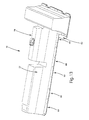
- FIG. 7 is a top perspective view of a battery clamp of FIG. 1 ;
- FIG. 8 is a perspective view of an exemplary embodiment of a lateral rib of FIG. 1 ;
- FIG. 9 is a perspective view of another exemplary embodiment of a lateral rib of FIG. 1 ;
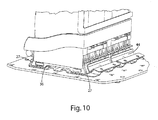
- FIG. 10 is a partial perspective view of the mounting system of FIG. 1 with a battery module disposed therein;
- FIG. 11 is a partial end view of the assembly of FIG. 10 ;
- FIG. 12 is a partial perspective view of the mounting system of FIG. 2 with two battery modules disposed therein;
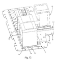
- FIG. 13 is a perspective view of an assembly of the components of FIG. 1 illustrating a plurality of battery modules disposed therein.
- this invention provides a battery mounting system for mounting a plurality of battery modules.
- the invention provides a battery tray that accepts a plurality of battery modules to form a battery pack, while also providing a combination of fixed and detachable retainers that enable insertion and retention of individual battery modules into the battery pack and removal of individual battery modules from the battery pack, both during assembly of the battery pack, and later in conjunction with service during the course of its operating life.
- the battery tray may be disposed on a base plate to provide additional support for the battery tray, as well as enabling the integration of more than one battery tray, as well as the battery modules associated therewith, into a battery pack. Where multiple battery trays are integrated on a base plate, the battery trays may be oriented on the base plate in different directions.
- the battery mounting system of the present invention provides a system for mounting a modular assembly of battery modules as a battery pack that may be used in various applications including those where the devices which are in power communication with the battery pack are subject to movement, such as, for example, various motorized vehicles, aircraft, watercraft, trains and the like.
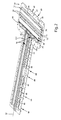
- battery mounting system 10 includes a battery tray 12.
- battery mounting system 10 may also include more than one battery tray 12, and where more than one battery tray 12 is used, the trays may have the same configuration or they may have different configurations. Battery trays having different configurations are illustrated in FIGS. 1 and 2 by battery tray 12 and battery tray 12.1. Battery tray 12 and battery tray 12.1 have substantially the same features, as explained further below, although they may have different sizes, including different lengths and widths. However, they may each also incorporate distinctive features, such as extension 14 shown on battery tray 12.1 (see FIGS. 1 and 2 ).
- Battery tray 12 and battery tray 12.1 each have a base 16, a retainer side 18 and an attachment side 20. Retainer side 18 is opposite attachment side 20 across the width of the battery trays 12, 12.1. Battery tray 12 and battery tray 12.1 each have length such that they are operative to receive a plurality of battery modules 22, as may be understood from FIGS. 10-12 , and is illustrated particularly in FIG. 13 .
- Base 16 provides support for battery modules 22 and particularly is adapted for pressing engagement with module base 36.
- Base 16 may include strengthening rib 38 which extends lengthwise along base 16. As illustrated in FIGS. 1-5 , this may also include a plurality of ribs 38, such as the two ribs 38 shown in these figures. The number of ribs 38, as well as their location, spacing, width and height may be selected so as to provide the required stiffness and strength of base 16 and battery tray 22 along its length.
- Base 16 may also incorporate one or more cut-outs or openings 40 along its length. Cut-outs 40 are used to reduce the weight of the battery tray, such as battery trays 12, 12.1. Cut-outs 40 will be selected and incorporated, including their number, size, shape, orientation and other factors so as to achieve the required strength characteristics of base 16 and the battery tray while also satisfying design requirements for the weight of the battery tray, such as the minimization of its weight.
- Retainer side 18 has a retainer 24 which extends at least partially along the length of trays 12, 12.1, as illustrated in FIGS. 1-6 . As may be seen in FIGS. 1-2 , retainer 24 extends along the entire length of battery tray 12, while retainer 24 extends only partially along the length of battery tray 12.1. While in many cases retainer 24 may extend along all or substantially all of the length of the battery tray, it will at a minimum extend at least partially along the length of the battery tray. Retainer 24 is operative to capture a retention feature of the battery module 22, such as one of a pair of opposing tapered flanges 26, as illustrated in FIGS. 10-13 . Tapered flanges 26 each may have a retention surface 27 as shown in FIGS.
- Retainer 24 may have any suitable shape for retaining the retention feature of battery module 22, including an inwardly and upwardly extending tapered wall 28.
- Tapered wall 28 may preferably be adapted to provide pressing engagement against tapered flange 26.
- Tapered wall 28 may also be adapted to include a vertical wall portion 30 which is adapted to a vertical wall 32 of battery module 22.
- tapered wall 28 has a taper angle ( ⁇ ) that is adapted to the taper angle ( ⁇ ) which tapered flange 26 makes with the base of battery module 22, as shown in FIG. 11 .
- Taper angle ( ⁇ ) may be adapted to match the taper angle ( ⁇ ) of tapered flange 26 so as to provide contact along substantially all of the surface of tapered wall 28, excepting vertical wall portion 30, or taper angle ( ⁇ ) may be selected so as to establish line contact between tapered flange 26 and tapered wall 28.
- Taper angle ( ⁇ ) may be any suitable angle, but generally will be selected to be less than or equal to about 60°,and more particularly less than or equal to about 45°. Thus, the taper angle ( ⁇ ) will generally also be selected to be within this range. Smaller taper angles ( ⁇ ) are advantageous in that they reduce the contact area footprint of battery modules 22, both with regard to the size of battery mounting system 10, as well as shipping and storage of the battery modules 22.
- Retainer 24 may be incorporated by any suitable method or means.
- retainer 24 may be formed as tapered wall 28 from an integral sheet used to form the battery tray.
- retainer 24 may also be added to base 16 on retainer side 18, such as by welding tapered element to base 16 which includes tapered wall 28; however, such added processes would generally not be expected to be cost competitive with formed retainer 24 structures.
- retainer 24 may also include a plurality of inwardly projecting retainer gussets 34 located between tapered wall 28 and base 16.
- Retainer gussets 34 may be incorporated by forming retainer gussets 34 at spaced intervals along tapered wall 28 by deforming associated portions of tapered wall 28, base 16, or both of them. Retainer gussets 34 reinforce tapered wall 28 and make it more resistant to deflection in conjunction with lateral forces and bending moments that may be applied thereto upon installation of battery modules 22, or during use of the battery pack. In this regard, retainer gussets 34 act as a strengthening rib interposed between tapered wall 28 and base 16.
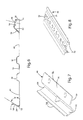
- the battery tray also incorporates an attachment structure 42 on attachment side 20.
- Attachment structure 42 is operative for the detachable attachment of retainer plates 44 (see FIGS. 1 , 2 and 7 ).
- Attachment structure 42 includes a plurality of spaced bores 46 located along the length of the battery tray on the attachment side 20.
- Attachment structure 42 is preferably a raised structure to provide sufficient thickness for use of connectors, such as threaded bolts to attach retainer plates 44 to attachment structure 42. This may be accomplished by increasing the thickness of retainer side 20, or by forming attachment side 20 to raise the upper surface 48 of attachment structure 42 sufficiently to enable use of threaded fasteners, while also maintaining a planar lower surface 50 of attachment structure 42, and more generally of the battery tray.
- Raised pockets 52 incorporate spaced bores 46 to provide attachment structure 42. Raised pockets 52 may also incorporate, on lower surface 50 proximate to and in axial alignment with bores 46, a corresponding plurality of welded nuts 51 (see FIG. 6 ) having threaded bores which are adapted to receive a threaded connector, such as a threaded bolt (not shown) for attachment of retainer plates 44 in the positions shown (for example in FIG. 2 ).
- Raised pockets 52 may be formed so that the pockets have respective upper pocket surfaces 54 that taper outwardly and downwardly toward attachment side 20. Front pocket surfaces 56 of raised pockets 52 may also taper downwardly and inwardly toward strengthening ribs 38.
- Upper surfaces 54 and front surfaces 56 are the attachment surfaces to which lower surfaces 58 of respective retainer plates 44 are attached.
- the taper angles (i.e., angles from the horizontal) of upper surfaces 54 and front surfaces 56 may be selected so as to cradle and pre-position the retainer plates 44 as they are placed into position, prior to insertion of connectors, such as threaded bolts, for retention of battery modules 22.
- the battery tray may be formed from any suitable material, including various ferrous alloys, such as steel.
- battery tray is made from a formable, high-strength steel, such as ASTM 1020.
- ASTM 1020 As indicated, the battery tray may have any suitable size, including the length and width, and any suitable thickness.
- battery trays 12,12.1 were made from 1.5 mm thick high-strength steel, ASTM 1020, and was fabricated by stamping to include a retainer 24 having a tapered wall 28, two strengthening ribs 38, cut-outs 40 and attachment structure 42, including a plurality of raised pockets 52, as shown in FIGS. 1-6 .
- battery mounting system 10 may also include base plate 60.
- Base plate 60 may be provided to house one or more battery trays, and in the case where more than one battery tray is used, to integrate the respective battery trays.
- the battery trays may be oriented with their lengths or longitudinal axes 62 oriented in the same direction, or different directions, and if in different directions in as many different directions as there are battery trays.
- a single battery tray may be constructed in a bent (e.g., intersecting straight sections), curved or other configurations, including various closed shape configurations (e.g., triangular, rectangular, circular, various polyhedrons), such that it has multiple straight sections having more than one longitudinal axis, or axes which extend in different directions, or such that the longitudinal axis is curved.
- base plate 60 is used to house and integrate two battery trays 12, 12.1, and these trays are disposed and oriented such that their longitudinal axes 62 are substantially orthogonal to one another.
- Base plate 60 has an upper surface 64 and a lower surface 66.
- Battery trays are disposed on upper surface 64 by attaching the lower surface 50 of battery trays 12,12.1 thereto.
- the attachment may be accomplished as a detachable attachment, such as by the use of various detachable fasteners (e.g., passing threaded bolts through bores in both the battery trays and base plates together with threaded nuts), or as a fixed attachment by permanently joining the battery trays and base plates together (e.g., using various welds, brazes, adhesives and the like).
- Base plates may have any suitable size and shape for housing the battery trays. The size and shape may be related to the size, shape and orientation of the battery trays being housed, or may have a different shape. As shown in FIGS.
- base plate 60 may have a substantially T-shaped configurations. This configuration is particularly advantageous in various motor vehicle applications, or applications in other types of craft, where the vehicle or other craft is substantially symmetric about a central plane, or where weight distribution about a central line or plane is desirable, because the T-shaped battery mounting system 10 is relatively compact and can be oriented symmetrically about such a central plane, generally by appropriate orientation of longitudinal axis 62 of battery tray 12.1 within the plane. Further, the lateral portion of the T-shaped systems associated with battery tray 12 can be associated with various laterally oriented features of such vehicles or craft, including various laterally oriented bulkheads, such as a vehicle firewall, the front or rear seats and the like.
- the base plate may be formed from any suitable material, including various ferrous alloys, such as steel.
- base plate was made from a formable, high-strength steel, such as ASTM 1020. As indicated, the base plate may have any suitable size and shape including the length and width, and any suitable thickness.
- base plate 60 was made from a 1.0 mm thick high-strength steel, ASTM 1020 and was fabricated by stamping, as shown in FIGS. 1 and 2 . Battery trays 12,12.1 may be disposed base plate 60 by welding.
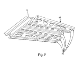
- mounting system 10 may also incorporate one or more lateral ribs 68 disposed on lower surface 66 of base plate 60.
- Lateral ribs 68 may be incorporated to stiffen and strengthen battery mounting system 10, particularly across the width of battery mounting system 10, and battery trays 12, 12.1. Any suitable number of lateral ribs 68 may be used to provide the desired stiffness to battery mounting system 10 and base plate 60. As shown in FIGS. 1 and 2 , five may be incorporated along the length of battery tray 12.1 and two along the length of battery tray 12, with one lateral rib 69 shared between their which provides laterally extending channels 70 with reference to both battery trays, as shown in FIG. 9 .
- Lateral ribs 68 may have any suitable shape to provide stiffening as described above.
- lateral ribs 68 incorporate two channels 70 having an arcuate cross-section formed in a flat sheet 72 by stamping.
- Lateral ribs 68 also incorporate a plurality of rib cut-outs 74 along their length.
- Lateral ribs 68 may have any suitable size, including their length and width, but generally will be selected so as to be complimentary to the width of the base plate 60 as indicated herein. It is also believed that all or a portion of the rib structure provided by discrete lateral ribs 68 may be disposed on the base plate 60 by forming this structure directly into base plate 60.
- Lateral ribs may be formed from any suitable material, including various ferrous alloys, such as steel.
- lateral ribs are made from formable, high-strength steel, such as ASTM 1030. As indicated, lateral ribs may have any suitable size, including any length and width, and any suitable thickness.
- lateral ribs 26 were made from 1.6 mm thick high-strength steel, ASTM 1030.
- Lateral ribs 68 were fabricated by stamping to include channel 70 and rib cut-out 74, as shown in FIG. 8 . Lateral ribs 68 and 69 may be disposed on base plate 60 by welding.
- the base plate, battery trays and lateral ribs may be assembled to form a base plate subassembly in the manner described herein.
- the base plate subassembly may include a corrosion resistant and electrically insulating coating, such as a powder coat.
- battery mounting system 10 may also incorporate a resilient sheet.
- Resilient sheet 76 is operative as a vibration dampening element to reduce the tendency for vibration to be exchanged between battery mounting system 10 and battery modules 22 mounted thereon.
- Resilient sheet 76 may comprise a plurality of resilient sheets 76 disposed on upper surface 48 of the battery tray, such as battery trays 12, 12.1.
- Resilient sheets 76 are preferably disposed on upper surface 48 between strengthening rib or ribs 38 and retainer 24 on one side and attachment structure 42 on the other side of the battery tray.
- Resilient sheets 76 will generally extend at least partially along the length of the battery tray and may extend along substantially the entire length of the battery tray as shown in FIGS. 1-3 .
- Resilient sheets 76 may have any suitable size, including their length and width, shape and thickness. These aspects of resilient sheets 76 will generally be selected in conjunction with the overall size and shape of battery mounting system 10 as well as battery modules 22.
- Resilient sheet 76 may be formed from any suitable material, including various elastomers, such as natural or synthetic rubber, silicone and the like.
- resilient sheets 76 were made from synthetic rubber.
- resilient sheets may have any suitable size, including length and width, and any suitable thickness.
- resilient sheets were made from 1-3 mm thick synthetic rubber and was fabricated by excising the rectangular forms shown larger pre-formed sheet of this material.
- Resilient sheets 76 may be attached to battery trays using a suitable adhesive.
- Battery mounting system 10 may also incorporate one or more battery clamps 44 for clamping a battery module or portion thereof.
- a plurality of battery clamps 44 was used, as illustrated in FIGS. 1-3 and 7 .
- Battery clamps 44 each have a clamp retainer end 78 and a clamp attachment end 80.
- the clamp retainer end 78 has a clamp retainer 82.
- Clamp retainer 82 is operative to capture a retention feature of battery modules 22, such as one of a pair of opposing tapered flanges 26, as illustrated in FIGS. 10-13 .
- Tapered flanges 26 each may have a retention surface 27 as shown in FIGS. 10-11 operative for bearing engagement with clamp retainer 82.
- Clamp retainer 82 may have any suitable shape for retaining the retention feature of battery module 22, including an inwardly and upwardly extending clamp tapered wall 94.
- Clamp tapered wall 94 may preferably be adapted to provide pressing engagement against tapered flange 26.
- Clamp tapered wall 94 may also be adapted to include a clamp vertical wall portion 96 which is adapted to a vertical wall 32 of battery module 22.
- clamp tapered wall 94 has a taper angle that is developed in conjunction with the inclination of upper surface 54 to yield an installed taper angle ( ⁇ ') that is adapted to the taper angle ( ⁇ ) which tapered flange 26 makes with the base ofbattery module 22, as shown in FIG. 11 .
- Installed taper angle ( ⁇ ') may be adapted to match the taper angle ( ⁇ ) of tapered flange 26 so as to provide contact along substantially all of the surface of clamp tapered wall 94, excepting vertical wall portion 96, or installed taper angle ( ⁇ ') may be selected so as to establish line contact between tapered flange 26 and tapered wall 28.
- Installed taper angle ( ⁇ ') may be any suitable angle, but generally will be selected to be less than or equal to about 60°, and more particularly less than or equal to about 45°. Thus, the taper angle ( ⁇ ) will generally also be selected to be within this range.
- Clamp retainer 82 is formed as a substantially v-shaped recess 84 in the plate structure that comprises battery clamp 44.
- clamp gussets 86 provide additional stiffness and strength to clamp retainer 82 as clamp retainer 82 is placed in contact with and provides pressing engagement to tapered flange 26 of battery module 22.
- Clamp retainer 82 may be incorporated by any suitable method or means.
- clamp retainer 82 may be formed as v-shaped recess from an integral sheet used to form the battery clamp 44.
- Clamp attachment ends 80 of battery clamps 44 each incorporate a clamp attachment structure 87.
- Clamp attachment structure may include a plurality of clamp bores 88, such as the two such bores shown in FIG. 7 .
- Clamp bores 88 are operative to receive a corresponding plurality of connectors (not shown) for insertion through clamp bores 88 and attachment to attachment structure 42 in the manner described herein.
- This may include a plurality of threaded bolts (not shown) as the connectors which are threaded into attachment structure 42 such as the plurality of welded nuts 51 described above associated with attachment structure 42. Threaded bolts may be inserted in the manner described and tightened against an upper clamp surface 90 to cause clamp retainer 82 to provide bearing pressure against retention surface 27 of battery module 22. This clamping pressure is used to retain battery module 22 to battery trays 12, 12.1.
- a plurality of battery clamps 44 may be employed with each battery module 22.
- Clamp resilient sheet 92 may be disposed on the clamp tapered wall 94 of battery clamp 44.
- Clamp resilient sheet 92 provides vibration damping in a manner similar to that described above with regard to resilient sheet 76. It may be disposed on the clamp tapered wall 94 by an adhesive.
- battery clamps 44 may be identical, or they may be different, for example, to accommodate different battery trays adapted to house battery modules having different configurations.
- Battery clamps may be formed from any suitable material, including various ferrous alloys, such as steel.
- battery clamps are made from formable, high-strength steel, such as ASTM 1020.
- battery clamps may have any suitable size, including any length and width, and any suitable thickness.
- lateral ribs 26 were made from 2 mm thick high-strength steel, ASTM 1030.
- Battery clamps 44 were fabricated by stamping to include clamp gusset 86 and clamp bores 88, as shown in FIG. 7 .
- Battery clamps may include a corrosion resistant and electrically insulating coating, such as a powder coat.
- Battery mounting system 10 may also incorporate a cover 98, as shown in FIGS. 1 and 13 .
- Cover 98 has an internal cavity that is adapted to house a plurality of battery modules 22 as shown in FIG. 13 and cover substantially all of the surface of base plate 60, including the battery trays.
- Cover is disposed on base plate 60, and preferably is detachably attached to base plate 60 with a plurality of fasteners, such as threaded bolts and associated threaded nuts. Detachable attachment permits cover 98 to be fixed to base plate 60 during the manufacture and use of the battery pack, but permits removal and replacement of the individual battery modules upon its detachment.
- Cover 60 may be made of materials of sufficient strength to permits cover 60 to act as a strengthening structural member of battery mounting system 10 as well as a protective cover for battery modules 22.
- Cover 98 may be formed from any suitable material, including various engineering thermoplastics and reinforced composites thereof.
- cover 98 was made from a sheet molding compound (SMC) comprising a vinyl ester.
- SMC sheet molding compound
- battery clamps may have any suitable size, including any length and width, and any suitable thickness.
Abstract
Description
- This invention relates generally to battery mounting systems, and, more particularly, to mounting systems for a plurality of battery modules.
- Vehicles using fossil fuel, such as gasoline and diesel oil, create exhaust gases which generally include various pollutants. A technology of using storage or secondary batteries, which can be charged and discharged, as a power source for vehicles has attracted considerable attention as one method of solving the above-mentioned problem. As a result, electric vehicles (EV), which are operated using only a battery, and hybrid electric vehicles (HEV), which jointly use a battery and a conventional combustion engine, have been developed, and some are now being used commercially. Various nickel-metal hydride (NiMH) secondary batteries have been widely used as the power source in EV and HEV applications. More recently, however, the use of lithium-ion secondary batteries has been proposed.
- High output and large capacity are needed for such secondary batteries to be used as the power source. For this reason, such batteries are typically constructed from a plurality of smaller battery cells (unit cells) that are interconnected in series or in parallel with each other to form a battery module. A plurality of Battery modules is interconnected to obtain a battery pack having the desired output and capacity characteristics.
- In order to use battery packs of the type described above in various applications, including applications where the devices which are in power communication with the battery pack are subject to movement, such as, for example, various motorized vehicles, aircraft, watercraft, trains and the like, it is generally desirable to establish a battery mount which may be used to secure the battery pack to the device with which it is in power communication and also secure the battery modules that make up the battery pack with respect to one another. Using a mount to secure the battery pack and modules in the manner described enables electrical interconnection of the battery pack with the devices with which it is in powered communication. In some applications, it is also desirable that the mount provide physical protection for the battery pack, such that the battery modules are covered. While various types of battery mounts for mounting individual batteries are known including certain covered mounts, and such mounts may be used to mount individual battery modules, these individual mounts are generally not desirable for use to mount the plurality of battery modules associated with a battery pack, as they require securing the battery modules individually. Therefore, it is desirable to develop mounting systems for mounting a plurality of battery modules as used in battery packs of the types described above.
- In general terms, this invention provides a battery mounting system for mounting a plurality of battery modules. The invention provides a battery tray that accepts a plurality of battery modules to form a battery pack, while also providing a combination of fixed and detachable retainers that enable insertion of individual battery modules into the battery pack and removal of individual battery modules from the battery pack, both during assembly of the battery pack and later in conjunction with service during the course of its operating life. The battery tray may be disposed on a base plate to provide additional support for the battery tray, as well as enabling the integration of more than one battery tray, as well as the battery modules associated therewith, into a battery pack. Where multiple battery trays are integrated on a base plate, the battery trays may be oriented on the base plate in different directions. The present invention provides a battery mounting system for modular assembly and packaging of battery modules into a battery pack that may be mounted, for example, in a motor vehicle or other applications that require modular battery pack assemblies.
- These and other features and advantages of this invention will become more apparent to those skilled in the art from the detailed description of a preferred embodiment. The drawings that accompany the detailed description are described below.
- The following is a brief description of the drawings wherein like elements are numbered alike in the several views:
-
FIG. 1 is an exploded perspective view of an exemplary embodiment of a battery mounting system of the present invention; -
FIG. 2 is a perspective view of an assembly of certain of the components ofFIG. 1 ; -
FIG. 3 is a partial front view of the assembly ofFIG. 2 ; -
FIG. 4 is a top perspective view of the battery tray ofFIG. 1 ; -
FIG. 5 is a bottom perspective view of the battery tray ofFIG. 1 ; -
FIG. 6 is a cross-section of the battery tray ofFIG. 4 taken along section 6-6; -
FIG. 7 is a top perspective view of a battery clamp ofFIG. 1 ; -
FIG. 8 is a perspective view of an exemplary embodiment of a lateral rib ofFIG. 1 ; -
FIG. 9 is a perspective view of another exemplary embodiment of a lateral rib ofFIG. 1 ; -
FIG. 10 is a partial perspective view of the mounting system ofFIG. 1 with a battery module disposed therein; -
FIG. 11 is a partial end view of the assembly ofFIG. 10 ; -
FIG. 12 is a partial perspective view of the mounting system ofFIG. 2 with two battery modules disposed therein; and -
FIG. 13 is a perspective view of an assembly of the components ofFIG. 1 illustrating a plurality of battery modules disposed therein. - In general terms, this invention provides a battery mounting system for mounting a plurality of battery modules. The invention provides a battery tray that accepts a plurality of battery modules to form a battery pack, while also providing a combination of fixed and detachable retainers that enable insertion and retention of individual battery modules into the battery pack and removal of individual battery modules from the battery pack, both during assembly of the battery pack, and later in conjunction with service during the course of its operating life. The battery tray may be disposed on a base plate to provide additional support for the battery tray, as well as enabling the integration of more than one battery tray, as well as the battery modules associated therewith, into a battery pack. Where multiple battery trays are integrated on a base plate, the battery trays may be oriented on the base plate in different directions. The battery mounting system of the present invention provides a system for mounting a modular assembly of battery modules as a battery pack that may be used in various applications including those where the devices which are in power communication with the battery pack are subject to movement, such as, for example, various motorized vehicles, aircraft, watercraft, trains and the like.
- Referring to
FIGS. 1-13 , an exemplary embodiment of the present invention includes abattery mounting system 10. Referring more particularly toFIGS. 1-6 ,battery mounting system 10 includes abattery tray 12. As illustrated inFIGS. 1 and2 ,battery mounting system 10 may also include more than onebattery tray 12, and where more than onebattery tray 12 is used, the trays may have the same configuration or they may have different configurations. Battery trays having different configurations are illustrated inFIGS. 1 and2 bybattery tray 12 and battery tray 12.1.Battery tray 12 and battery tray 12.1 have substantially the same features, as explained further below, although they may have different sizes, including different lengths and widths. However, they may each also incorporate distinctive features, such as extension 14 shown on battery tray 12.1 (seeFIGS. 1 and2 ).Battery tray 12 and battery tray 12.1 each have abase 16, aretainer side 18 and anattachment side 20.Retainer side 18 isopposite attachment side 20 across the width of thebattery trays 12, 12.1.Battery tray 12 and battery tray 12.1 each have length such that they are operative to receive a plurality ofbattery modules 22, as may be understood fromFIGS. 10-12 , and is illustrated particularly inFIG. 13 . -
Base 16 provides support forbattery modules 22 and particularly is adapted for pressing engagement withmodule base 36.Base 16 may include strengtheningrib 38 which extends lengthwise alongbase 16. As illustrated inFIGS. 1-5 , this may also include a plurality ofribs 38, such as the tworibs 38 shown in these figures. The number ofribs 38, as well as their location, spacing, width and height may be selected so as to provide the required stiffness and strength ofbase 16 andbattery tray 22 along its length.Base 16 may also incorporate one or more cut-outs oropenings 40 along its length. Cut-outs 40 are used to reduce the weight of the battery tray, such asbattery trays 12, 12.1. Cut-outs 40 will be selected and incorporated, including their number, size, shape, orientation and other factors so as to achieve the required strength characteristics ofbase 16 and the battery tray while also satisfying design requirements for the weight of the battery tray, such as the minimization of its weight. -
Retainer side 18 has aretainer 24 which extends at least partially along the length oftrays 12, 12.1, as illustrated inFIGS. 1-6 . As may be seen inFIGS. 1-2 ,retainer 24 extends along the entire length ofbattery tray 12, whileretainer 24 extends only partially along the length of battery tray 12.1. While inmany cases retainer 24 may extend along all or substantially all of the length of the battery tray, it will at a minimum extend at least partially along the length of the battery tray.Retainer 24 is operative to capture a retention feature of thebattery module 22, such as one of a pair of opposingtapered flanges 26, as illustrated inFIGS. 10-13 .Tapered flanges 26 each may have aretention surface 27 as shown inFIGS. 10-11 operative for bearing engagement withretainer 24.Retainer 24 may have any suitable shape for retaining the retention feature ofbattery module 22, including an inwardly and upwardly extending taperedwall 28.Tapered wall 28 may preferably be adapted to provide pressing engagement against taperedflange 26.Tapered wall 28 may also be adapted to include avertical wall portion 30 which is adapted to avertical wall 32 ofbattery module 22. As shown inFIG. 6 , taperedwall 28 has a taper angle (θ) that is adapted to the taper angle (β) which taperedflange 26 makes with the base ofbattery module 22, as shown inFIG. 11 . Taper angle (θ) may be adapted to match the taper angle (β) of taperedflange 26 so as to provide contact along substantially all of the surface of taperedwall 28, exceptingvertical wall portion 30, or taper angle (θ) may be selected so as to establish line contact betweentapered flange 26 and taperedwall 28. Taper angle (θ) may be any suitable angle, but generally will be selected to be less than or equal to about 60°,and more particularly less than or equal to about 45°. Thus, the taper angle (β) will generally also be selected to be within this range. Smaller taper angles (β) are advantageous in that they reduce the contact area footprint ofbattery modules 22, both with regard to the size ofbattery mounting system 10, as well as shipping and storage of thebattery modules 22.Retainer 24 may be incorporated by any suitable method or means. For example,retainer 24 may be formed as taperedwall 28 from an integral sheet used to form the battery tray. However, it is believed thatretainer 24 may also be added tobase 16 onretainer side 18, such as by welding tapered element to base 16 which includes taperedwall 28; however, such added processes would generally not be expected to be cost competitive with formedretainer 24 structures. As illustrated inFIGS. 1 ,2 ,4 and 5 ,retainer 24 may also include a plurality of inwardly projectingretainer gussets 34 located between taperedwall 28 andbase 16.Retainer gussets 34 may be incorporated by formingretainer gussets 34 at spaced intervals along taperedwall 28 by deforming associated portions of taperedwall 28,base 16, or both of them.Retainer gussets 34 reinforce taperedwall 28 and make it more resistant to deflection in conjunction with lateral forces and bending moments that may be applied thereto upon installation ofbattery modules 22, or during use of the battery pack. In this regard,retainer gussets 34 act as a strengthening rib interposed between taperedwall 28 andbase 16. - The battery tray also incorporates an
attachment structure 42 onattachment side 20.Attachment structure 42 is operative for the detachable attachment of retainer plates 44 (seeFIGS. 1 ,2 and7 ).Attachment structure 42 includes a plurality of spaced bores 46 located along the length of the battery tray on theattachment side 20.Attachment structure 42 is preferably a raised structure to provide sufficient thickness for use of connectors, such as threaded bolts to attachretainer plates 44 toattachment structure 42. This may be accomplished by increasing the thickness ofretainer side 20, or by formingattachment side 20 to raise the upper surface 48 ofattachment structure 42 sufficiently to enable use of threaded fasteners, while also maintaining a planarlower surface 50 ofattachment structure 42, and more generally of the battery tray. This may be accomplished, for example, by the formation of a plurality of raised pockets 52. Raised pockets 52 incorporate spacedbores 46 to provideattachment structure 42. Raised pockets 52 may also incorporate, onlower surface 50 proximate to and in axial alignment withbores 46, a corresponding plurality of welded nuts 51 (seeFIG. 6 ) having threaded bores which are adapted to receive a threaded connector, such as a threaded bolt (not shown) for attachment ofretainer plates 44 in the positions shown (for example inFIG. 2 ). Raised pockets 52 may be formed so that the pockets have respective upper pocket surfaces 54 that taper outwardly and downwardly towardattachment side 20. Front pocket surfaces 56 of raisedpockets 52 may also taper downwardly and inwardly toward strengtheningribs 38.Upper surfaces 54 andfront surfaces 56 are the attachment surfaces to whichlower surfaces 58 ofrespective retainer plates 44 are attached. The taper angles (i.e., angles from the horizontal) ofupper surfaces 54 andfront surfaces 56 may be selected so as to cradle and pre-position theretainer plates 44 as they are placed into position, prior to insertion of connectors, such as threaded bolts, for retention ofbattery modules 22. - The battery tray may be formed from any suitable material, including various ferrous alloys, such as steel. In an exemplary embodiment, battery tray is made from a formable, high-strength steel, such as ASTM 1020. As indicated, the battery tray may have any suitable size, including the length and width, and any suitable thickness. In an exemplary embodiment,
battery trays 12,12.1 were made from 1.5 mm thick high-strength steel, ASTM 1020, and was fabricated by stamping to include aretainer 24 having a taperedwall 28, two strengtheningribs 38, cut-outs 40 andattachment structure 42, including a plurality of raisedpockets 52, as shown inFIGS. 1-6 . - As shown in an exemplary embodiment in
FIGS. 1 ,2 ,10-13 ,battery mounting system 10 may also includebase plate 60.Base plate 60 may be provided to house one or more battery trays, and in the case where more than one battery tray is used, to integrate the respective battery trays. In the case wherebase plate 60 integrates multiple battery trays, the battery trays may be oriented with their lengths orlongitudinal axes 62 oriented in the same direction, or different directions, and if in different directions in as many different directions as there are battery trays. Further, a single battery tray may be constructed in a bent (e.g., intersecting straight sections), curved or other configurations, including various closed shape configurations (e.g., triangular, rectangular, circular, various polyhedrons), such that it has multiple straight sections having more than one longitudinal axis, or axes which extend in different directions, or such that the longitudinal axis is curved. As shown inFigs 1 ,2 ,10-13 ,base plate 60 is used to house and integrate twobattery trays 12, 12.1, and these trays are disposed and oriented such that theirlongitudinal axes 62 are substantially orthogonal to one another.Base plate 60 has an upper surface 64 and a lower surface 66. Battery trays are disposed on upper surface 64 by attaching thelower surface 50 ofbattery trays 12,12.1 thereto. The attachment may be accomplished as a detachable attachment, such as by the use of various detachable fasteners (e.g., passing threaded bolts through bores in both the battery trays and base plates together with threaded nuts), or as a fixed attachment by permanently joining the battery trays and base plates together (e.g., using various welds, brazes, adhesives and the like). Base plates may have any suitable size and shape for housing the battery trays. The size and shape may be related to the size, shape and orientation of the battery trays being housed, or may have a different shape. As shown inFIGS. 1 and2 ,base plate 60 may have a substantially T-shaped configurations. This configuration is particularly advantageous in various motor vehicle applications, or applications in other types of craft, where the vehicle or other craft is substantially symmetric about a central plane, or where weight distribution about a central line or plane is desirable, because the T-shapedbattery mounting system 10 is relatively compact and can be oriented symmetrically about such a central plane, generally by appropriate orientation oflongitudinal axis 62 of battery tray 12.1 within the plane. Further, the lateral portion of the T-shaped systems associated withbattery tray 12 can be associated with various laterally oriented features of such vehicles or craft, including various laterally oriented bulkheads, such as a vehicle firewall, the front or rear seats and the like. - The base plate may be formed from any suitable material, including various ferrous alloys, such as steel. In an exemplary embodiment, base plate was made from a formable, high-strength steel, such as ASTM 1020. As indicated, the base plate may have any suitable size and shape including the length and width, and any suitable thickness. In an exemplary embodiment,
base plate 60 was made from a 1.0 mm thick high-strength steel, ASTM 1020 and was fabricated by stamping, as shown inFIGS. 1 and2 .Battery trays 12,12.1 may be disposedbase plate 60 by welding. - Referring to
FIGS. 1 ,2 and8 , mountingsystem 10 may also incorporate one or morelateral ribs 68 disposed on lower surface 66 ofbase plate 60.Lateral ribs 68 may be incorporated to stiffen and strengthenbattery mounting system 10, particularly across the width ofbattery mounting system 10, andbattery trays 12, 12.1. Any suitable number oflateral ribs 68 may be used to provide the desired stiffness tobattery mounting system 10 andbase plate 60. As shown inFIGS. 1 and2 , five may be incorporated along the length of battery tray 12.1 and two along the length ofbattery tray 12, with onelateral rib 69 shared between their which provides laterally extendingchannels 70 with reference to both battery trays, as shown inFIG. 9 .Lateral ribs 68 may have any suitable shape to provide stiffening as described above. In an exemplary embodiment,lateral ribs 68 incorporate twochannels 70 having an arcuate cross-section formed in aflat sheet 72 by stamping.Lateral ribs 68 also incorporate a plurality of rib cut-outs 74 along their length.Lateral ribs 68 may have any suitable size, including their length and width, but generally will be selected so as to be complimentary to the width of thebase plate 60 as indicated herein. It is also believed that all or a portion of the rib structure provided by discretelateral ribs 68 may be disposed on thebase plate 60 by forming this structure directly intobase plate 60. - Lateral ribs may be formed from any suitable material, including various ferrous alloys, such as steel. In an exemplary embodiment, lateral ribs are made from formable, high-strength steel, such as ASTM 1030. As indicated, lateral ribs may have any suitable size, including any length and width, and any suitable thickness. In an exemplary embodiment,
lateral ribs 26 were made from 1.6 mm thick high-strength steel, ASTM 1030.Lateral ribs 68 were fabricated by stamping to includechannel 70 and rib cut-out 74, as shown inFIG. 8 .Lateral ribs base plate 60 by welding. - The base plate, battery trays and lateral ribs may be assembled to form a base plate subassembly in the manner described herein. The base plate subassembly may include a corrosion resistant and electrically insulating coating, such as a powder coat.
- Referring to
FIGS. 1-3 ,battery mounting system 10 may also incorporate a resilient sheet.Resilient sheet 76 is operative as a vibration dampening element to reduce the tendency for vibration to be exchanged betweenbattery mounting system 10 andbattery modules 22 mounted thereon.Resilient sheet 76 may comprise a plurality ofresilient sheets 76 disposed on upper surface 48 of the battery tray, such asbattery trays 12, 12.1.Resilient sheets 76 are preferably disposed on upper surface 48 between strengthening rib orribs 38 andretainer 24 on one side andattachment structure 42 on the other side of the battery tray.Resilient sheets 76 will generally extend at least partially along the length of the battery tray and may extend along substantially the entire length of the battery tray as shown inFIGS. 1-3 .Resilient sheets 76 may have any suitable size, including their length and width, shape and thickness. These aspects ofresilient sheets 76 will generally be selected in conjunction with the overall size and shape ofbattery mounting system 10 as well asbattery modules 22. -
Resilient sheet 76 may be formed from any suitable material, including various elastomers, such as natural or synthetic rubber, silicone and the like. In an exemplary embodiment,resilient sheets 76 were made from synthetic rubber. As indicated, resilient sheets may have any suitable size, including length and width, and any suitable thickness. In an exemplary embodiment, resilient sheets were made from 1-3 mm thick synthetic rubber and was fabricated by excising the rectangular forms shown larger pre-formed sheet of this material.Resilient sheets 76 may be attached to battery trays using a suitable adhesive. -
Battery mounting system 10 may also incorporate one or more battery clamps 44 for clamping a battery module or portion thereof. In an exemplary embodiment, a plurality of battery clamps 44 was used, as illustrated inFIGS. 1-3 and7 . Battery clamps 44 each have a clamp retainer end 78 and aclamp attachment end 80. The clamp retainer end 78 has aclamp retainer 82.Clamp retainer 82 is operative to capture a retention feature ofbattery modules 22, such as one of a pair of opposing taperedflanges 26, as illustrated inFIGS. 10-13 .Tapered flanges 26 each may have aretention surface 27 as shown inFIGS. 10-11 operative for bearing engagement withclamp retainer 82.Clamp retainer 82 may have any suitable shape for retaining the retention feature ofbattery module 22, including an inwardly and upwardly extending clamp tapered wall 94. Clamp tapered wall 94 may preferably be adapted to provide pressing engagement against taperedflange 26. Clamp tapered wall 94 may also be adapted to include a clamp vertical wall portion 96 which is adapted to avertical wall 32 ofbattery module 22. As shown inFIG. 6 , clamp tapered wall 94 has a taper angle that is developed in conjunction with the inclination ofupper surface 54 to yield an installed taper angle (θ') that is adapted to the taper angle (β) which taperedflange 26 makes with thebase ofbattery module 22, as shown inFIG. 11 . Installed taper angle (θ') may be adapted to match the taper angle (β) of taperedflange 26 so as to provide contact along substantially all of the surface of clamp tapered wall 94, excepting vertical wall portion 96, or installed taper angle (θ') may be selected so as to establish line contact betweentapered flange 26 and taperedwall 28. Installed taper angle (θ') may be any suitable angle, but generally will be selected to be less than or equal to about 60°, and more particularly less than or equal to about 45°. Thus, the taper angle (β) will generally also be selected to be within this range.Clamp retainer 82 is formed as a substantially v-shaped recess 84 in the plate structure that comprisesbattery clamp 44. Within v-shaped recess 84, one or more inwardly protruding clamp gussets 86 may be formed. Clamp gussets 86 provide additional stiffness and strength to clampretainer 82 asclamp retainer 82 is placed in contact with and provides pressing engagement to taperedflange 26 ofbattery module 22.Clamp retainer 82 may be incorporated by any suitable method or means. For example, clampretainer 82 may be formed as v-shaped recess from an integral sheet used to form thebattery clamp 44. Clamp attachment ends 80 of battery clamps 44 each incorporate a clamp attachment structure 87. Clamp attachment structure may include a plurality of clamp bores 88, such as the two such bores shown inFIG. 7 . Clamp bores 88 are operative to receive a corresponding plurality of connectors (not shown) for insertion through clamp bores 88 and attachment toattachment structure 42 in the manner described herein. This may include a plurality of threaded bolts (not shown) as the connectors which are threaded intoattachment structure 42 such as the plurality of welded nuts 51 described above associated withattachment structure 42. Threaded bolts may be inserted in the manner described and tightened against anupper clamp surface 90 to causeclamp retainer 82 to provide bearing pressure againstretention surface 27 ofbattery module 22. This clamping pressure is used to retainbattery module 22 tobattery trays 12, 12.1. A plurality of battery clamps 44 may be employed with eachbattery module 22. Clampresilient sheet 92 may be disposed on the clamp tapered wall 94 ofbattery clamp 44. Clampresilient sheet 92 provides vibration damping in a manner similar to that described above with regard toresilient sheet 76. It may be disposed on the clamp tapered wall 94 by an adhesive. For a givenbattery mounting system 10, battery clamps 44 may be identical, or they may be different, for example, to accommodate different battery trays adapted to house battery modules having different configurations. - Battery clamps may be formed from any suitable material, including various ferrous alloys, such as steel. In an exemplary embodiment, battery clamps are made from formable, high-strength steel, such as ASTM 1020. As indicated, battery clamps may have any suitable size, including any length and width, and any suitable thickness. In an exemplary embodiment,
lateral ribs 26 were made from 2 mm thick high-strength steel, ASTM 1030. Battery clamps 44 were fabricated by stamping to include clamp gusset 86 and clamp bores 88, as shown inFIG. 7 . Battery clamps may include a corrosion resistant and electrically insulating coating, such as a powder coat. -
Battery mounting system 10 may also incorporate acover 98, as shown inFIGS. 1 and13 .Cover 98 has an internal cavity that is adapted to house a plurality ofbattery modules 22 as shown inFIG. 13 and cover substantially all of the surface ofbase plate 60, including the battery trays. Cover is disposed onbase plate 60, and preferably is detachably attached tobase plate 60 with a plurality of fasteners, such as threaded bolts and associated threaded nuts. Detachable attachment permits cover 98 to be fixed tobase plate 60 during the manufacture and use of the battery pack, but permits removal and replacement of the individual battery modules upon its detachment.Cover 60 may be made of materials of sufficient strength to permits cover 60 to act as a strengthening structural member ofbattery mounting system 10 as well as a protective cover forbattery modules 22. -
Cover 98 may be formed from any suitable material, including various engineering thermoplastics and reinforced composites thereof.. In an exemplary embodiment, cover 98 was made from a sheet molding compound (SMC) comprising a vinyl ester. As indicated, battery clamps may have any suitable size, including any length and width, and any suitable thickness. - The foregoing invention has been described in accordance with the relevant legal standards, thus the description is exemplary rather than limiting in nature. Variations and modifications to the disclosed embodiment may become apparent to those skilled in the art and do come within the scope of the invention. Accordingly, the scope of legal protection afforded this invention can only be determined by studying the following claims.
Claims (28)
- A battery mounting system, comprising:a battery tray having a base, a retainer side and an attachment side opposed across a width thereof, the battery tray having a length operative to receive a plurality of battery modules, the retainer side having a retainer extending at least partially along a length of the tray, the attachment side having an attachment structure extending at least partially along the length of the tray, the retainer operative to engage a first retention surface associated with each of the plurality of battery modules.
- The battery mounting system of claim 1, wherein the retainer comprises an inwardly and upwardly extending tapered wall having a taper angle.
- The battery mounting system of claim 1, wherein the retainer also comprises a plurality of spaced gussets joining the tapered wall and the base along the length of the battery tray.
- The battery mounting system of claim 1, wherein the battery tray has a rib extending lengthwise along the base.
- The battery mounting system of claim 1, wherein the base has a plurality of spaced cut-outs located along the length.
- The battery mounting system of claim 1, wherein the attachment structure comprises a plurality of spaced bores.
- The battery mounting system of claim 6, wherein the spaced bores are located in a raised portion of the attachment structure.
- The battery mounting system of claim 7, wherein the raised portion comprises a plurality of raised pockets and the bores are associated with the pockets.
- The battery mounting system of claim 8, wherein each of the pockets has an upper surface that tapers outwardly and downwardly toward the attachment side.
- The battery mounting system of claim 1 further comprising a base plate having an upper surface and a lower surface, wherein a lower surface of the battery tray is disposed on the upper surface of the base plate.
- The battery mounting system of claim 10, further comprising a plurality of lateral ribs disposed on the lower surface of the base plate.
- The battery mounting system of claim 1, further comprising a cover operative to be disposed on the upper surface of the base plate and enclose the plurality of battery modules.
- The battery mounting system of claim 1, further comprising a resilient sheet attached to an upper surface of the battery tray.
- The battery mounting system of claim 1, further comprising a plurality of resilient sheets disposed on an upper surface of the battery tray, wherein a first resilient sheet is disposed proximate the retainer at least partially along the length of the sheet and a second sheet is disposed proximate the attachment structure at least partially along the length of the sheet.
- The battery mounting system of claim 14, wherein the retainer comprises an inwardly and upwardly extending tapered wall, and the first resilient sheet is disposed on the tapered wall.
- The battery mounting system of claim 1, further comprising a plurality of battery clamps each having a retainer end and an attachment end, the retainer end having a plate retainer and the attachment end having an clamp attachment structure, the plate attachment structure operative for detachable attachment to the attachment structure of the battery tray through a connector.
- The battery mounting system of claim 16, wherein the plate retainer comprises an inwardly and upwardly extending tapered wall having a taper angle.
- The battery mounting system of claim 2, further comprising a plurality of battery clamps each having a retainer end and an attachment end, the retainer end having a clamp retainer and the clamp attachment end having a clamp attachment structure, the clamp attachment structure operative for detachable attachment to the attachment structure of the battery tray through a connector.
- The battery mounting system of claim 18, wherein the clamp retainer comprises an inwardly and upwardly extending clamp tapered wall having an installed taper angle.
- The battery mounting system of claim 18, wherein the taper angle and the installed taper angle are the same.
- The battery mounting system of claim 18, further comprising a resilient sheet disposed on the clamp tapered wall.
- A battery mounting system, comprising:a battery tray having a base, a retainer side and an attachment side opposed across a width thereof, the battery tray having a length operative to receive a plurality of battery modules, the retainer side having a retainer extending at least partially along the length of the tray, the attachment side having an attachment structure extending at least partially along the length of the tray, the retainer operative to engage a first retention surface associated with each of the plurality of battery modules;a base plate having an upper surface and a lower surface, wherein a lower surface of the battery tray is disposed on the upper surface of the base plate; anda plurality of battery clamps each having a clamp retainer end and a clamp attachment end, the clamp retainer end having a clamp retainer and the clamp attachment end having an clamp attachment structure, the clamp attachment structure of each attachment plate operative to engage a second retention surface associated with each of the plurality of battery modules through a connector.
- The battery mounting system of claim 22, further comprising a cover operative to be disposed on the upper surface of the base plate and enclose the plurality or battery modules.
- The battery mounting system of claim 22, further comprising a resilient sheet attached to an upper surface of the battery tray.
- The battery mounting system of claim 22, further comprising a plurality of lateral ribs disposed on the lower surface of the base plate.
- The battery mounting system of claim 22, wherein the retainer comprises an inwardly and upwardly extending tapered wall having a first taper angle and the plate retainer comprises an inwardly and upwardly extending tapered wall having a second taper angle.
- The battery mounting system of claim 22, further comprising a corrosion resistant and electrically insulating coating applied to exposed portions of the battery tray, base plate and battery clamps.
- The battery mounting system of claim 22, wherein the base plate has a T-shape.
Applications Claiming Priority (2)
| Application Number | Priority Date | Filing Date | Title |
|---|---|---|---|
| US12/165,298 US8110300B2 (en) | 2008-06-30 | 2008-06-30 | Battery mounting system |
| PCT/KR2009/003432 WO2010002140A2 (en) | 2008-06-30 | 2009-06-25 | Battery mounting system |
Publications (3)
| Publication Number | Publication Date |
|---|---|
| EP2293362A2 true EP2293362A2 (en) | 2011-03-09 |
| EP2293362A4 EP2293362A4 (en) | 2013-12-25 |
| EP2293362B1 EP2293362B1 (en) | 2018-01-17 |
Family
ID=41447854
Family Applications (1)
| Application Number | Title | Priority Date | Filing Date |
|---|---|---|---|
| EP09773676.3A Active EP2293362B1 (en) | 2008-06-30 | 2009-06-25 | Battery mounting system |
Country Status (6)
| Country | Link |
|---|---|
| US (1) | US8110300B2 (en) |
| EP (1) | EP2293362B1 (en) |
| JP (2) | JP5461544B2 (en) |
| KR (1) | KR101045855B1 (en) |
| CN (1) | CN102067352B (en) |
| WO (1) | WO2010002140A2 (en) |
Cited By (1)
| Publication number | Priority date | Publication date | Assignee | Title |
|---|---|---|---|---|
| EP3116048A4 (en) * | 2014-05-07 | 2017-07-19 | LG Chem, Ltd. | Battery pack comprising holddown bracket |
Families Citing this family (58)
| Publication number | Priority date | Publication date | Assignee | Title |
|---|---|---|---|---|
| US9140501B2 (en) * | 2008-06-30 | 2015-09-22 | Lg Chem, Ltd. | Battery module having a rubber cooling manifold |
| WO2010138209A1 (en) * | 2009-05-28 | 2010-12-02 | Phoenix Motorcars, Inc. | Battery module with related devices and methods |
| US9263713B2 (en) | 2010-05-26 | 2016-02-16 | Samsung Sdi Co., Ltd. | Battery pack |
| KR20120044853A (en) * | 2010-10-28 | 2012-05-08 | 현대자동차주식회사 | Battery pack case assembly for electric vehicles using plastic composite |
| BR112013023584A2 (en) | 2011-03-17 | 2016-12-06 | Ev Chip Energy Ltd | battery pack system |
| DE102011078235B4 (en) * | 2011-06-28 | 2023-10-26 | Robert Bosch Gmbh | Contact element for mechanical, thermal and electrical contact with an energy storage device |
| KR101273080B1 (en) * | 2011-07-21 | 2013-06-10 | 기아자동차주식회사 | Mounting structure for battery in electric vehicle |
| US8911892B2 (en) | 2012-05-21 | 2014-12-16 | Lg Chem, Ltd. | Battery module mounting assembly and method for mounting a battery module to a base plate |
| US8822056B2 (en) | 2012-05-30 | 2014-09-02 | Honda Motor Co., Ltd. | Methods and systems for supporting a battery |
| KR101947831B1 (en) * | 2012-06-14 | 2019-02-13 | 현대자동차주식회사 | High voltage battery pack for vehicle |
| EP2719564B1 (en) | 2012-09-21 | 2016-08-24 | Samsung SDI Co., Ltd. | Battery system for a motor vehicle |
| US9034510B2 (en) | 2012-09-25 | 2015-05-19 | Lg Chem, Ltd. | Battery pack and method of securing a plurality of battery modules in the battery pack |
| ES2531384T3 (en) * | 2012-10-26 | 2015-03-13 | Moog Unna Gmbh | System consisting of a battery container and a container housing for mounting the battery container in a battery compartment of a wind power plant |
| KR101428276B1 (en) * | 2012-12-12 | 2014-08-07 | 현대자동차주식회사 | Battery tray for vehicle |
| JP6044405B2 (en) * | 2013-03-21 | 2016-12-14 | 株式会社豊田自動織機 | Battery pack and battery module assembly method |
| DE102013205637A1 (en) * | 2013-03-28 | 2014-10-02 | Jungheinrich Aktiengesellschaft | The battery holder |
| WO2014194264A1 (en) * | 2013-05-31 | 2014-12-04 | King Products, LLC | Battery holder and isolation assembly |
| JP5900481B2 (en) | 2013-12-25 | 2016-04-06 | トヨタ自動車株式会社 | Vehicle panel structure |
| US9590216B2 (en) * | 2014-04-30 | 2017-03-07 | Ford Global Technologies, Llc | Electric vehicle battery assembly enclosure |
| US9553288B2 (en) | 2014-08-20 | 2017-01-24 | Ford Global Technologies, Llc | Step configuration for traction battery housing |
| KR101840417B1 (en) * | 2014-09-15 | 2018-03-20 | 주식회사 엘지화학 | Battery Module Comprising Cooling Structure having Minimized Bending of Coolant Channel |
| US10033022B2 (en) | 2014-09-30 | 2018-07-24 | Johnson Controls Technology Company | Battery module retention structure |
| US20160369940A1 (en) | 2015-06-18 | 2016-12-22 | Cummins Emission Solutions Inc. | Sensor mounting table for aftertreatment systems |
| KR102127273B1 (en) * | 2015-11-05 | 2020-06-26 | 주식회사 엘지화학 | Battery Pack Having Support Member for Improved Strength |
| KR102066911B1 (en) * | 2015-12-04 | 2020-01-16 | 주식회사 엘지화학 | Pack Housing Having gasket Member and Battery Pack Containing the Same |
| JP6215975B2 (en) * | 2016-01-12 | 2017-10-18 | 本田技研工業株式会社 | Battery fixing structure |
| KR102072220B1 (en) | 2016-01-12 | 2020-01-31 | 주식회사 엘지화학 | Battery Pack Capable of Minimizing Space for Mounting to Device |
| WO2018033880A2 (en) | 2016-08-17 | 2018-02-22 | Shape Corp. | Battery support and protection structure for a vehicle |
| US10381621B2 (en) * | 2016-11-01 | 2019-08-13 | Ford Global Technologies, Llc | Traction battery energy absorbing method and assembly |
| US10230083B2 (en) * | 2016-11-01 | 2019-03-12 | Ford Global Technologies, Llc | Traction battery retention assembly |
| CN110383526A (en) | 2017-01-04 | 2019-10-25 | 形状集团 | The Vehicular battery support holder structure of node module |
| WO2018213306A1 (en) | 2017-05-16 | 2018-11-22 | Shape Corp. | Vehicle battery tray having tub-based component |
| WO2018213383A1 (en) | 2017-05-16 | 2018-11-22 | Shape Corp. | Vehicle battery tray with integrated battery retention and support features |
| WO2018213475A1 (en) | 2017-05-16 | 2018-11-22 | Shape Corp. | Polarized battery tray for a vehicle |
| CN107170936A (en) * | 2017-06-30 | 2017-09-15 | 格林美(武汉)新能源汽车服务有限公司 | Lightweight electrokinetic cell bag |
| WO2019055658A2 (en) | 2017-09-13 | 2019-03-21 | Shape Corp. | Vehicle battery tray with tubular peripheral wall |
| WO2019071013A1 (en) | 2017-10-04 | 2019-04-11 | Shape Corp. | Battery tray floor assembly for electric vehicles |
| KR102444124B1 (en) * | 2017-10-16 | 2022-09-16 | 주식회사 엘지에너지솔루션 | Battery module and battery pack having the same |
| US10826034B2 (en) * | 2017-11-20 | 2020-11-03 | Ford Global Technologies, Llc | Mounting clamps for securing groupings of battery cells |
| CN107978711B (en) * | 2017-12-06 | 2023-05-12 | 力帆实业(集团)股份有限公司 | Battery core unit of battery pack of electric automobile |
| EP3511231B1 (en) * | 2018-01-10 | 2023-12-06 | Volvo Car Corporation | Reinforcement structure |
| US10773582B2 (en) * | 2018-02-19 | 2020-09-15 | Dura Operating, Llc | Automobile vehicle battery tray with side impact rails |
| CN112055898A (en) | 2018-03-01 | 2020-12-08 | 形状集团 | Cooling system integrated with vehicle battery tray |
| US11688910B2 (en) | 2018-03-15 | 2023-06-27 | Shape Corp. | Vehicle battery tray having tub-based component |
| DE102018106399A1 (en) * | 2018-03-19 | 2019-09-19 | Muhr Und Bender Kg | Housing arrangement for receiving electrical storage means and method for producing a housing assembly |
| DE102018110269A1 (en) * | 2018-04-27 | 2019-10-31 | Airbus Operations Gmbh | Battery holding device and aircraft with such a battery holding device |
| CN108550737A (en) * | 2018-05-16 | 2018-09-18 | 湖南江南汽车制造有限公司 | A kind of Battery case |
| KR102396436B1 (en) * | 2018-09-21 | 2022-05-09 | 주식회사 엘지에너지솔루션 | Battery pack including fixing member, device including the same, and the battry pack manufacturing method |
| US11276898B2 (en) * | 2018-11-13 | 2022-03-15 | Rivian Ip Holdings, Llc | Battery module frame configuration |
| US11285820B2 (en) * | 2018-11-13 | 2022-03-29 | Dus Operating Inc. | Battery tray assembly for a vehicle |
| EP3947020B1 (en) * | 2019-03-26 | 2023-06-07 | Volvo Truck Corporation | A device for installing traction batteries, a system and a vehicle |
| US11916242B2 (en) * | 2019-10-11 | 2024-02-27 | Briggs & Stratton, Llc | Commercial flexible battery pack with secondary output control |
| DE102019128476A1 (en) | 2019-10-22 | 2021-04-22 | Dr. Ing. H.C. F. Porsche Aktiengesellschaft | Traction battery system for a motor vehicle |
| US11364956B2 (en) * | 2019-12-11 | 2022-06-21 | Ford Global Technologies, Llc | Motor vehicle floor assembly with recesses for electrical lines and electrical modules |
| CN112098688B (en) * | 2020-09-25 | 2023-04-14 | 苏州富强科技有限公司 | Carrier for battery detection |
| KR20220078359A (en) * | 2020-12-03 | 2022-06-10 | 주식회사 엘지에너지솔루션 | Battery Pack, Electric Storage System, and Vehicle |
| CN113370789B (en) * | 2021-06-18 | 2024-01-30 | 浙江吉利控股集团有限公司 | Automobile storage battery protection device and automobile |
| EP4274009A1 (en) * | 2022-05-05 | 2023-11-08 | Automotive Cells Company SE | Assembly for the formation of an electrical member comprising electrochemical cells and associated method for mounting |
Citations (7)
| Publication number | Priority date | Publication date | Assignee | Title |
|---|---|---|---|---|
| US5378555A (en) * | 1993-12-27 | 1995-01-03 | General Motors Corporation | Electric vehicle battery pack |
| JPH11297290A (en) * | 1998-04-10 | 1999-10-29 | Nissan Motor Co Ltd | Fixing structure of vehicle battery |
| EP1069632A1 (en) * | 1999-07-15 | 2001-01-17 | Mgi Coutier (S.A.) | Fastening arrangement of an accumulator battery |
| US6230834B1 (en) * | 1999-09-16 | 2001-05-15 | Daimlerchrysler Corporation | Battery mounting system |
| JP2006185815A (en) * | 2004-12-28 | 2006-07-13 | Toyota Motor Corp | Battery pack |
| FR2891515A1 (en) * | 2005-10-05 | 2007-04-06 | Raymond Et Cie Soc En Commandi | Car battery mounting system comprises tray, into which battery fits, with ribs which lodge over lugs near base of battery, one rib having lug on it which can be moved to locking position by handle and fixed by wedge between lug and handle |
| JP2008056194A (en) * | 2006-09-04 | 2008-03-13 | Toyota Motor Corp | Tray for storage device |
Family Cites Families (19)
| Publication number | Priority date | Publication date | Assignee | Title |
|---|---|---|---|---|
| US2933548A (en) * | 1956-05-16 | 1960-04-19 | Chloride Electrical Storage Co | Electric storage battery carriers |
| US3866704A (en) * | 1973-02-08 | 1975-02-18 | East Penn Manufacturing Compan | Battery holddown |
| US4936409A (en) * | 1989-08-14 | 1990-06-26 | Nix Charles D | Battery hold down device |
| JP2819927B2 (en) * | 1992-03-02 | 1998-11-05 | トヨタ自動車株式会社 | Battery holder for electric vehicles |
| US5558949A (en) * | 1993-12-27 | 1996-09-24 | Honda Giken Kogyo Kabushiki Kaisha | Battery box |
| JPH07232564A (en) * | 1994-02-25 | 1995-09-05 | Nissan Motor Co Ltd | Battery installation structure of electric vehicle |
| KR100256750B1 (en) * | 1997-11-10 | 2000-05-15 | 정몽규 | Battery tray for electric vehicle |
| KR19990052099A (en) * | 1997-12-20 | 1999-07-05 | 정몽규 | Battery retainer |
| US6399239B2 (en) * | 1998-01-19 | 2002-06-04 | Johnson Controls Technology Company | Battery system |
| JP4259694B2 (en) * | 1999-09-29 | 2009-04-30 | 富士重工業株式会社 | Vehicle battery mounting structure |
| JP4416266B2 (en) * | 1999-10-08 | 2010-02-17 | パナソニック株式会社 | Sealed prismatic battery |
| JP2001313018A (en) * | 2000-04-28 | 2001-11-09 | Toyota Motor Corp | Power supply unit and its manufacturing method |
| US6451475B1 (en) * | 2000-07-05 | 2002-09-17 | East Penn Manufacturing Company, Inc. | Front access interlocking modular cell tray assembly |
| JP2002225570A (en) * | 2001-01-30 | 2002-08-14 | Toyota Motor Corp | Battery fixing structure |
| JP2004291715A (en) * | 2003-03-26 | 2004-10-21 | Toyota Motor Corp | Automobile |
| KR100503853B1 (en) * | 2003-10-13 | 2005-07-27 | 현대에너셀 주식회사 | Tray assembly for packing battery |
| US7540102B2 (en) * | 2005-03-02 | 2009-06-02 | Wisconsin Engineering, Cz S.R.O. | Snow blower apparatus |
| JP5141026B2 (en) * | 2006-02-27 | 2013-02-13 | トヨタ自動車株式会社 | In-vehicle structure of power storage pack |
| KR100828102B1 (en) * | 2006-12-22 | 2008-05-08 | 주식회사 포스코 | Method and apparatus for silicon powder production |
-
2008
- 2008-06-30 US US12/165,298 patent/US8110300B2/en active Active
- 2008-07-26 KR KR1020080073273A patent/KR101045855B1/en active IP Right Grant
-
2009
- 2009-06-25 CN CN2009801221278A patent/CN102067352B/en active Active
- 2009-06-25 EP EP09773676.3A patent/EP2293362B1/en active Active
- 2009-06-25 JP JP2011516132A patent/JP5461544B2/en active Active
- 2009-06-25 WO PCT/KR2009/003432 patent/WO2010002140A2/en active Application Filing
-
2013
- 2013-11-13 JP JP2013235133A patent/JP5773462B2/en active Active
Patent Citations (7)
| Publication number | Priority date | Publication date | Assignee | Title |
|---|---|---|---|---|
| US5378555A (en) * | 1993-12-27 | 1995-01-03 | General Motors Corporation | Electric vehicle battery pack |
| JPH11297290A (en) * | 1998-04-10 | 1999-10-29 | Nissan Motor Co Ltd | Fixing structure of vehicle battery |
| EP1069632A1 (en) * | 1999-07-15 | 2001-01-17 | Mgi Coutier (S.A.) | Fastening arrangement of an accumulator battery |
| US6230834B1 (en) * | 1999-09-16 | 2001-05-15 | Daimlerchrysler Corporation | Battery mounting system |
| JP2006185815A (en) * | 2004-12-28 | 2006-07-13 | Toyota Motor Corp | Battery pack |
| FR2891515A1 (en) * | 2005-10-05 | 2007-04-06 | Raymond Et Cie Soc En Commandi | Car battery mounting system comprises tray, into which battery fits, with ribs which lodge over lugs near base of battery, one rib having lug on it which can be moved to locking position by handle and fixed by wedge between lug and handle |
| JP2008056194A (en) * | 2006-09-04 | 2008-03-13 | Toyota Motor Corp | Tray for storage device |
Non-Patent Citations (1)
| Title |
|---|
| See also references of WO2010002140A2 * |
Cited By (2)
| Publication number | Priority date | Publication date | Assignee | Title |
|---|---|---|---|---|
| EP3116048A4 (en) * | 2014-05-07 | 2017-07-19 | LG Chem, Ltd. | Battery pack comprising holddown bracket |
| US10553844B2 (en) | 2014-05-07 | 2020-02-04 | Lg Chem, Ltd. | Battery pack having hold down bracket |
Also Published As
| Publication number | Publication date |
|---|---|
| CN102067352A (en) | 2011-05-18 |
| WO2010002140A3 (en) | 2010-03-11 |
| US20090325049A1 (en) | 2009-12-31 |
| JP2014063747A (en) | 2014-04-10 |
| CN102067352B (en) | 2013-09-04 |
| JP2011526728A (en) | 2011-10-13 |
| JP5773462B2 (en) | 2015-09-02 |
| WO2010002140A2 (en) | 2010-01-07 |
| US8110300B2 (en) | 2012-02-07 |
| JP5461544B2 (en) | 2014-04-02 |
| KR20100003138A (en) | 2010-01-07 |
| KR101045855B1 (en) | 2011-07-01 |
| EP2293362A4 (en) | 2013-12-25 |
| EP2293362B1 (en) | 2018-01-17 |
Similar Documents
| Publication | Publication Date | Title |
|---|---|---|
| US8110300B2 (en) | Battery mounting system | |
| RU2684972C1 (en) | Battery installation structure | |
| US11355804B2 (en) | Removable battery component carrier, battery system including removable battery component carriers and vehicle including the battery system | |
| US11888169B2 (en) | Energy storage module and assembly method | |
| US8968912B2 (en) | Method and apparatus for manufacturing a battery for a vehicle | |
| US20130095360A1 (en) | Battery cell with integrated mounting foot | |
| US10170739B2 (en) | Pin mount for battery module | |
| EP1984966B1 (en) | Medium and large size battery module of vertical stacking structure | |
| EP3331055A1 (en) | Removable battery component carrier, battery system including removable battery component carriers and vehicle including the battery system | |
| JP2007069801A (en) | Structure of power supply to be mounted on vehicle | |
| CN108001181B (en) | Traction battery retention assembly | |
| US20170214013A1 (en) | Battery pack array retention | |
| US20160204401A1 (en) | Reconfigurable vehicular battery enclosure components | |
| US11780336B2 (en) | Battery assembly | |
| US20170331079A1 (en) | Battery compression inhibitor and battery module comprising same | |
| JP2011210451A (en) | Power supply device | |
| US20240063511A1 (en) | Traction battery pack busbar supporting assembly and supporting method | |
| US20110061958A1 (en) | Power system for electric vehicles which employ modular exchangeable battery packs | |
| KR101859684B1 (en) | Battery Module Having Bus Bar Assembly and Battery Pack Comprising the Same | |
| US20230302887A1 (en) | Traction battery packs with cell-to-pack battery systems housed within irregularly shaped enclosures | |
| CN116805745A (en) | Support assembly for traction battery pack having cell-pack battery system | |
| CN117691286A (en) | Structural cross member assembly for traction battery pack | |
| CN117644781A (en) | Traction battery pack support system and method of securing a battery pack to an motorized vehicle | |
| CN117276783A (en) | Variable array retention strategy | |
| KR20230056613A (en) | Battery frame, battery pack, electric vehicle, method of assembling a battery frame, and method of assembling a battery pack |
Legal Events
| Date | Code | Title | Description |
|---|---|---|---|
| PUAI | Public reference made under article 153(3) epc to a published international application that has entered the european phase |
Free format text: ORIGINAL CODE: 0009012 |
|
| 17P | Request for examination filed |
Effective date: 20101210 |
|
| AK | Designated contracting states |
Kind code of ref document: A2 Designated state(s): AT BE BG CH CY CZ DE DK EE ES FI FR GB GR HR HU IE IS IT LI LT LU LV MC MK MT NL NO PL PT RO SE SI SK TR |
|
| AX | Request for extension of the european patent |
Extension state: AL BA RS |
|
| DAX | Request for extension of the european patent (deleted) | ||
| A4 | Supplementary search report drawn up and despatched |
Effective date: 20131126 |
|
| RIC1 | Information provided on ipc code assigned before grant |
Ipc: H01M 2/20 20060101ALI20131120BHEP Ipc: B60L 11/18 20060101ALI20131120BHEP Ipc: H01M 2/10 20060101AFI20131120BHEP Ipc: H01M 2/02 20060101ALI20131120BHEP |
|
| 17Q | First examination report despatched |
Effective date: 20151014 |
|
| GRAP | Despatch of communication of intention to grant a patent |
Free format text: ORIGINAL CODE: EPIDOSNIGR1 |
|
| RIC1 | Information provided on ipc code assigned before grant |
Ipc: H01M 2/10 20060101AFI20171003BHEP Ipc: B60L 11/18 20060101ALI20171003BHEP Ipc: H01M 2/02 20060101ALI20171003BHEP |
|
| INTG | Intention to grant announced |
Effective date: 20171016 |
|
| GRAS | Grant fee paid |
Free format text: ORIGINAL CODE: EPIDOSNIGR3 |
|
| GRAA | (expected) grant |
Free format text: ORIGINAL CODE: 0009210 |
|
| AK | Designated contracting states |
Kind code of ref document: B1 Designated state(s): AT BE BG CH CY CZ DE DK EE ES FI FR GB GR HR HU IE IS IT LI LT LU LV MC MK MT NL NO PL PT RO SE SI SK TR |
|
| REG | Reference to a national code |
Ref country code: GB Ref legal event code: FG4D |
|
| REG | Reference to a national code |
Ref country code: CH Ref legal event code: EP |
|
| REG | Reference to a national code |
Ref country code: IE Ref legal event code: FG4D |
|
| REG | Reference to a national code |
Ref country code: AT Ref legal event code: REF Ref document number: 964980 Country of ref document: AT Kind code of ref document: T Effective date: 20180215 |
|
| REG | Reference to a national code |
Ref country code: DE Ref legal event code: R096 Ref document number: 602009050470 Country of ref document: DE |
|
| REG | Reference to a national code |
Ref country code: NL Ref legal event code: MP Effective date: 20180117 |
|
| REG | Reference to a national code |
Ref country code: FR Ref legal event code: PLFP Year of fee payment: 10 |
|
| REG | Reference to a national code |
Ref country code: LT Ref legal event code: MG4D |
|
| REG | Reference to a national code |
Ref country code: AT Ref legal event code: MK05 Ref document number: 964980 Country of ref document: AT Kind code of ref document: T Effective date: 20180117 |
|
| PG25 | Lapsed in a contracting state [announced via postgrant information from national office to epo] |
Ref country code: NL Free format text: LAPSE BECAUSE OF FAILURE TO SUBMIT A TRANSLATION OF THE DESCRIPTION OR TO PAY THE FEE WITHIN THE PRESCRIBED TIME-LIMIT Effective date: 20180117 |
|
| PG25 | Lapsed in a contracting state [announced via postgrant information from national office to epo] |
Ref country code: ES Free format text: LAPSE BECAUSE OF FAILURE TO SUBMIT A TRANSLATION OF THE DESCRIPTION OR TO PAY THE FEE WITHIN THE PRESCRIBED TIME-LIMIT Effective date: 20180117 Ref country code: HR Free format text: LAPSE BECAUSE OF FAILURE TO SUBMIT A TRANSLATION OF THE DESCRIPTION OR TO PAY THE FEE WITHIN THE PRESCRIBED TIME-LIMIT Effective date: 20180117 Ref country code: CY Free format text: LAPSE BECAUSE OF FAILURE TO SUBMIT A TRANSLATION OF THE DESCRIPTION OR TO PAY THE FEE WITHIN THE PRESCRIBED TIME-LIMIT Effective date: 20180117 Ref country code: LT Free format text: LAPSE BECAUSE OF FAILURE TO SUBMIT A TRANSLATION OF THE DESCRIPTION OR TO PAY THE FEE WITHIN THE PRESCRIBED TIME-LIMIT Effective date: 20180117 Ref country code: FI Free format text: LAPSE BECAUSE OF FAILURE TO SUBMIT A TRANSLATION OF THE DESCRIPTION OR TO PAY THE FEE WITHIN THE PRESCRIBED TIME-LIMIT Effective date: 20180117 Ref country code: NO Free format text: LAPSE BECAUSE OF FAILURE TO SUBMIT A TRANSLATION OF THE DESCRIPTION OR TO PAY THE FEE WITHIN THE PRESCRIBED TIME-LIMIT Effective date: 20180417 |
|
| PG25 | Lapsed in a contracting state [announced via postgrant information from national office to epo] |
Ref country code: IS Free format text: LAPSE BECAUSE OF FAILURE TO SUBMIT A TRANSLATION OF THE DESCRIPTION OR TO PAY THE FEE WITHIN THE PRESCRIBED TIME-LIMIT Effective date: 20180517 Ref country code: GR Free format text: LAPSE BECAUSE OF FAILURE TO SUBMIT A TRANSLATION OF THE DESCRIPTION OR TO PAY THE FEE WITHIN THE PRESCRIBED TIME-LIMIT Effective date: 20180418 Ref country code: PL Free format text: LAPSE BECAUSE OF FAILURE TO SUBMIT A TRANSLATION OF THE DESCRIPTION OR TO PAY THE FEE WITHIN THE PRESCRIBED TIME-LIMIT Effective date: 20180117 Ref country code: LV Free format text: LAPSE BECAUSE OF FAILURE TO SUBMIT A TRANSLATION OF THE DESCRIPTION OR TO PAY THE FEE WITHIN THE PRESCRIBED TIME-LIMIT Effective date: 20180117 Ref country code: SE Free format text: LAPSE BECAUSE OF FAILURE TO SUBMIT A TRANSLATION OF THE DESCRIPTION OR TO PAY THE FEE WITHIN THE PRESCRIBED TIME-LIMIT Effective date: 20180117 Ref country code: BG Free format text: LAPSE BECAUSE OF FAILURE TO SUBMIT A TRANSLATION OF THE DESCRIPTION OR TO PAY THE FEE WITHIN THE PRESCRIBED TIME-LIMIT Effective date: 20180417 Ref country code: AT Free format text: LAPSE BECAUSE OF FAILURE TO SUBMIT A TRANSLATION OF THE DESCRIPTION OR TO PAY THE FEE WITHIN THE PRESCRIBED TIME-LIMIT Effective date: 20180117 |
|
| RAP2 | Party data changed (patent owner data changed or rights of a patent transferred) |
Owner name: LG CHEM, LTD. |
|
| REG | Reference to a national code |
Ref country code: DE Ref legal event code: R097 Ref document number: 602009050470 Country of ref document: DE |
|
| PG25 | Lapsed in a contracting state [announced via postgrant information from national office to epo] |
Ref country code: IT Free format text: LAPSE BECAUSE OF FAILURE TO SUBMIT A TRANSLATION OF THE DESCRIPTION OR TO PAY THE FEE WITHIN THE PRESCRIBED TIME-LIMIT Effective date: 20180117 Ref country code: EE Free format text: LAPSE BECAUSE OF FAILURE TO SUBMIT A TRANSLATION OF THE DESCRIPTION OR TO PAY THE FEE WITHIN THE PRESCRIBED TIME-LIMIT Effective date: 20180117 Ref country code: RO Free format text: LAPSE BECAUSE OF FAILURE TO SUBMIT A TRANSLATION OF THE DESCRIPTION OR TO PAY THE FEE WITHIN THE PRESCRIBED TIME-LIMIT Effective date: 20180117 |
|
| PLBE | No opposition filed within time limit |
Free format text: ORIGINAL CODE: 0009261 |
|
| STAA | Information on the status of an ep patent application or granted ep patent |
Free format text: STATUS: NO OPPOSITION FILED WITHIN TIME LIMIT |
|
| PG25 | Lapsed in a contracting state [announced via postgrant information from national office to epo] |
Ref country code: DK Free format text: LAPSE BECAUSE OF FAILURE TO SUBMIT A TRANSLATION OF THE DESCRIPTION OR TO PAY THE FEE WITHIN THE PRESCRIBED TIME-LIMIT Effective date: 20180117 Ref country code: CZ Free format text: LAPSE BECAUSE OF FAILURE TO SUBMIT A TRANSLATION OF THE DESCRIPTION OR TO PAY THE FEE WITHIN THE PRESCRIBED TIME-LIMIT Effective date: 20180117 Ref country code: SK Free format text: LAPSE BECAUSE OF FAILURE TO SUBMIT A TRANSLATION OF THE DESCRIPTION OR TO PAY THE FEE WITHIN THE PRESCRIBED TIME-LIMIT Effective date: 20180117 |
|
| 26N | No opposition filed |
Effective date: 20181018 |
|
| REG | Reference to a national code |
Ref country code: CH Ref legal event code: PL |
|
| PG25 | Lapsed in a contracting state [announced via postgrant information from national office to epo] |
Ref country code: SI Free format text: LAPSE BECAUSE OF FAILURE TO SUBMIT A TRANSLATION OF THE DESCRIPTION OR TO PAY THE FEE WITHIN THE PRESCRIBED TIME-LIMIT Effective date: 20180117 |
|
| REG | Reference to a national code |
Ref country code: BE Ref legal event code: MM Effective date: 20180630 |
|
| REG | Reference to a national code |
Ref country code: IE Ref legal event code: MM4A |
|
| PG25 | Lapsed in a contracting state [announced via postgrant information from national office to epo] |
Ref country code: MC Free format text: LAPSE BECAUSE OF FAILURE TO SUBMIT A TRANSLATION OF THE DESCRIPTION OR TO PAY THE FEE WITHIN THE PRESCRIBED TIME-LIMIT Effective date: 20180117 Ref country code: LU Free format text: LAPSE BECAUSE OF NON-PAYMENT OF DUE FEES Effective date: 20180625 |
|
| PG25 | Lapsed in a contracting state [announced via postgrant information from national office to epo] |
Ref country code: IE Free format text: LAPSE BECAUSE OF NON-PAYMENT OF DUE FEES Effective date: 20180625 Ref country code: LI Free format text: LAPSE BECAUSE OF NON-PAYMENT OF DUE FEES Effective date: 20180630 Ref country code: CH Free format text: LAPSE BECAUSE OF NON-PAYMENT OF DUE FEES Effective date: 20180630 |
|
| PG25 | Lapsed in a contracting state [announced via postgrant information from national office to epo] |
Ref country code: BE Free format text: LAPSE BECAUSE OF NON-PAYMENT OF DUE FEES Effective date: 20180630 |
|
| PG25 | Lapsed in a contracting state [announced via postgrant information from national office to epo] |
Ref country code: MT Free format text: LAPSE BECAUSE OF NON-PAYMENT OF DUE FEES Effective date: 20180625 |
|
| PG25 | Lapsed in a contracting state [announced via postgrant information from national office to epo] |
Ref country code: TR Free format text: LAPSE BECAUSE OF FAILURE TO SUBMIT A TRANSLATION OF THE DESCRIPTION OR TO PAY THE FEE WITHIN THE PRESCRIBED TIME-LIMIT Effective date: 20180117 |
|
| PG25 | Lapsed in a contracting state [announced via postgrant information from national office to epo] |
Ref country code: PT Free format text: LAPSE BECAUSE OF FAILURE TO SUBMIT A TRANSLATION OF THE DESCRIPTION OR TO PAY THE FEE WITHIN THE PRESCRIBED TIME-LIMIT Effective date: 20180117 Ref country code: HU Free format text: LAPSE BECAUSE OF FAILURE TO SUBMIT A TRANSLATION OF THE DESCRIPTION OR TO PAY THE FEE WITHIN THE PRESCRIBED TIME-LIMIT; INVALID AB INITIO Effective date: 20090625 |
|
| PG25 | Lapsed in a contracting state [announced via postgrant information from national office to epo] |
Ref country code: MK Free format text: LAPSE BECAUSE OF NON-PAYMENT OF DUE FEES Effective date: 20180117 |
|
| REG | Reference to a national code |
Ref country code: DE Ref legal event code: R079 Ref document number: 602009050470 Country of ref document: DE Free format text: PREVIOUS MAIN CLASS: H01M0002100000 Ipc: H01M0050200000 |
|
| P01 | Opt-out of the competence of the unified patent court (upc) registered |
Effective date: 20230408 |
|
| REG | Reference to a national code |
Ref country code: DE Ref legal event code: R081 Ref document number: 602009050470 Country of ref document: DE Owner name: LG ENERGY SOLUTION, LTD., KR Free format text: FORMER OWNER: LG CHEM, LTD., SEOUL, KR |
|
| PGFP | Annual fee paid to national office [announced via postgrant information from national office to epo] |
Ref country code: FR Payment date: 20230522 Year of fee payment: 15 Ref country code: DE Payment date: 20230522 Year of fee payment: 15 |
|
| REG | Reference to a national code |
Ref country code: GB Ref legal event code: 732E Free format text: REGISTERED BETWEEN 20230824 AND 20230831 |
|
| PGFP | Annual fee paid to national office [announced via postgrant information from national office to epo] |
Ref country code: GB Payment date: 20230523 Year of fee payment: 15 |