EP2293014A2 - Optisches Resonatorgyroskop mit Eingabestrahlmodulation, die für eine hohe Empfindlichkeit und niedrige Vorspannung optimiert ist - Google Patents
Optisches Resonatorgyroskop mit Eingabestrahlmodulation, die für eine hohe Empfindlichkeit und niedrige Vorspannung optimiert ist Download PDFInfo
- Publication number
- EP2293014A2 EP2293014A2 EP10171309A EP10171309A EP2293014A2 EP 2293014 A2 EP2293014 A2 EP 2293014A2 EP 10171309 A EP10171309 A EP 10171309A EP 10171309 A EP10171309 A EP 10171309A EP 2293014 A2 EP2293014 A2 EP 2293014A2
- Authority
- EP
- European Patent Office
- Prior art keywords
- phase modulation
- frequency
- modulation
- resonator
- phase
- Prior art date
- Legal status (The legal status is an assumption and is not a legal conclusion. Google has not performed a legal analysis and makes no representation as to the accuracy of the status listed.)
- Granted
Links
- 230000035945 sensitivity Effects 0.000 title claims abstract description 53
- 230000003287 optical effect Effects 0.000 title claims abstract description 23
- 230000010287 polarization Effects 0.000 claims abstract description 36
- 238000006880 cross-coupling reaction Methods 0.000 claims abstract description 26
- 238000000034 method Methods 0.000 claims abstract description 19
- 230000004044 response Effects 0.000 claims description 9
- 238000005259 measurement Methods 0.000 claims description 6
- 230000006870 function Effects 0.000 description 17
- 238000013178 mathematical model Methods 0.000 description 8
- 239000000835 fiber Substances 0.000 description 7
- 230000008878 coupling Effects 0.000 description 4
- 238000010168 coupling process Methods 0.000 description 4
- 238000005859 coupling reaction Methods 0.000 description 4
- 230000009467 reduction Effects 0.000 description 4
- 238000004458 analytical method Methods 0.000 description 3
- 238000013459 approach Methods 0.000 description 3
- 230000008033 biological extinction Effects 0.000 description 3
- 230000005540 biological transmission Effects 0.000 description 3
- 238000004590 computer program Methods 0.000 description 3
- 238000013461 design Methods 0.000 description 3
- 239000013307 optical fiber Substances 0.000 description 3
- 230000001902 propagating effect Effects 0.000 description 3
- 230000003595 spectral effect Effects 0.000 description 3
- 230000008859 change Effects 0.000 description 2
- 230000000694 effects Effects 0.000 description 2
- 230000014509 gene expression Effects 0.000 description 2
- 238000005457 optimization Methods 0.000 description 2
- 230000008569 process Effects 0.000 description 2
- 238000000926 separation method Methods 0.000 description 2
- 230000018199 S phase Effects 0.000 description 1
- 230000002238 attenuated effect Effects 0.000 description 1
- 238000004364 calculation method Methods 0.000 description 1
- 230000021615 conjugation Effects 0.000 description 1
- 230000007423 decrease Effects 0.000 description 1
- 238000012938 design process Methods 0.000 description 1
- 238000001514 detection method Methods 0.000 description 1
- 230000005684 electric field Effects 0.000 description 1
- 230000007613 environmental effect Effects 0.000 description 1
- 238000004519 manufacturing process Methods 0.000 description 1
- 238000012545 processing Methods 0.000 description 1
Images


Classifications
-
- G—PHYSICS
- G01—MEASURING; TESTING
- G01C—MEASURING DISTANCES, LEVELS OR BEARINGS; SURVEYING; NAVIGATION; GYROSCOPIC INSTRUMENTS; PHOTOGRAMMETRY OR VIDEOGRAMMETRY
- G01C19/00—Gyroscopes; Turn-sensitive devices using vibrating masses; Turn-sensitive devices without moving masses; Measuring angular rate using gyroscopic effects
- G01C19/58—Turn-sensitive devices without moving masses
- G01C19/64—Gyrometers using the Sagnac effect, i.e. rotation-induced shifts between counter-rotating electromagnetic beams
- G01C19/72—Gyrometers using the Sagnac effect, i.e. rotation-induced shifts between counter-rotating electromagnetic beams with counter-rotating light beams in a passive ring, e.g. fibre laser gyrometers
Definitions
- a resonator optical gyroscope is a rotation rate sensing device that includes a resonant cavity.
- the resonant cavity supports light waves propagating in opposite directions (without loss of generality, they are referred in the following to clockwise (CW) and counter-clockwise (CCW) directions, respectively).
- CW clockwise
- CCW counter-clockwise
- rotation rate can be determined.
- Resonator fiber optic gyroscope is a special kind of resonator gyroscope that uses optical fibers in the resonator.
- Optical fiber increases the gyro signal-to-noise (S/N) sensitivity without significantly increasing the size of the sensing loop.
- monochromatic light waves are typically sinusoidally phase/frequency modulated and coupled into the RFOG resonator in the CW and CCW directions. Fractions of light circulating inside the resonator are coupled out of the resonator and converted to electronic signals at photodetectors. The electrical signals are demodulated at the corresponding modulation frequencies and used to servo the input light frequencies to the resonance frequencies of the CW and CCW cavity.
- phase modulation behaves like a Mach-Zehnder interferometer with its two optical arms formed by the two orthogonal polarization paths of the modulator.
- Most of the optical power propagates in the optical path whose polarization state is aligned with the pass-axis of the modulator.
- a small amount of (cross-coupled) optical power propagates in the optical path whose polarization state is orthogonal to the pass-axis of the modulator.
- the interferences between the light waves propagating along the two orthogonal polarization axes of the modulator causes intensity modulation at the phase modulation frequency, leading to erroneous demodulation of the rate signals.
- Erroneous demodulation generates bias errors of the gyro.
- the present invention provides methods and systems to achieve high gyro signal-to-noise (S/N) sensitivity and low intensity modulation by optimizing input beam phase modulation amplitudes and frequencies.
- a single modulation amplitude/frequency selection simultaneously optimizes the gyro for both highest S/N sensitivity and lowest modulator induced intensity modulation.
- a method to optimize the phase-modulation amplitude (frequency) for a selected modulation frequency (amplitude) that maximizes the gyro S/N sensitivity is provided.
- the polarization cross-coupling induced intensity modulation can be nulled.
- the intensity modulation can be reduced to nearly zero while still achieving maximum gyro S/N sensitivity.
- Selection of different (but substantially close to optimal sensitivity) modulation frequencies for CW and CCW input lightwaves avoids bias instabilities due to back-scattering in the gyro sensing loop.
- resonator gyros can be constructed from many kinds of optical components (including those with optical fibers, optical waveguides, discrete optical components and free space, etc).
- the invention is applicable to gyros with multiple input light beams from one or multiple light sources in both CW and CCW directions.
- FIGURE 1 shows a high sensitivity, low bias resonator optical gyroscope 10 (typically a resonator fiber optic gyroscope (RFOG)) with functional blocks for input light modulation, output signal detection, demodulation and servo electronics.
- the RFOG 10 includes a monochromatic light source 11, an input polarization cross-coupling point 12, a phase modulator 13, an output polarization cross-coupling point 14, an optical isolator 15, an input coupler 16, an output coupler 17, a resonator 18, other optical components 19, a photo detector 20, an amplifier 21, a demodulator 22, a laser frequency controller 23, a sine wave generator 24, and a driver 25.
- CW clockwise
- CCW clockwise
- An output beam from the monochromatic light source 11 is phase-modulated by the phase modulator 13 and coupled into the resonator 18 in the CW direction at the input coupler 16.
- the optical isolator 15 is located between the coupler 16 and the modulator 13 to prevent any counterpropagating lightwaves (not shown) from returning to the monochromatic light source 11.
- a fraction of the circulating CW lightwaves are coupled out of the resonator 18 at the output coupler 17 and detected by the photo detector 20.
- a photo-current or voltage signal is amplified by the amplifier 21 and fed to the demodulator 22 for demodulation and processing.
- the sine wave generator 24 used to drive the phase-modulator 13 provides a reference frequency to the demodulator 22.
- a demodulated signal is used by the servo electronics to lock the laser frequency to the resonances of the CW resonator 18.
- a measured resonant frequency difference between the CW and CCW (similarly measured) directions determines the rotation rate.
- the points 12 and 14 generally represent points of polarization cross-coupling before and after the phase modulator 13 due to imperfect phase modulator fiber splices or polarization axis mismatch between the modulator waveguide and its pigtail fibers (not shown).
- the polarization cross-coupling at points 12 and 14 lead to light intensity modulation at the phase modulation frequency due to interference between the lightwaves propagating along the two orthogonal polarization axes of the modulator. This intensity modulation occurring at the phase modulator 13 causes erroneous demodulation of the rate signal and produce bias errors of the gyro.
- the first term on the right hand side of the equation is related to polarization cross-coupling induced field and the second term is the modulated main light beam.
- E 0 is the input light beam amplitude
- ⁇ ( t ) is the initial phase of the lightwave at time t
- ⁇ c is the lightwave center angular frequency (hereinafter, all angular frequencies will be referred to as frequencies for simplicity)
- ⁇ m is the phase modulation frequency
- M is the phase modulation amplitude in units of radians
- c . c . stands for complex conjugation
- k 1 and k 2 are the polarization amplitude cross-coupling coefficients at the points 12 and 14 respectively
- ⁇ is the phase modulator field polarization extinction ratio.
- k 1 , k 2 , and ⁇ are very small numbers.
- the impact of the first term on bias cannot be ignored for high performance gyros or when k 1 k 2 ⁇ is not small enough (e.g. >10 -6 ).
- the term ⁇ T ( t ) is the phase difference between the two light paths having orthogonal polarization states between the cross-coupling points 12 and 14. This phase difference varies with time upon environmental changes and is the cause of bias instability when cross-couplings are present.
- phase modulation and “frequency modulation” may be referring to the same modulation, but can be expressed in different units in the following statements.
- n is an integer number range from - ⁇ to + ⁇ .
- the above equation shows that the field of the modulated light contains many frequency components shifted from ⁇ c by integer numbers of the modulation frequency ⁇ m .
- the magnitude of the frequency components are governed by the phase modulation amplitude M and the Bessel functions.
- the polarization cross-coupled light beam expressed by the first term of the equation contributes only to the fundamental frequency component at ⁇ c , therefore its complex magnitude is proportional to J 0 ( M ) + k 1 k 2 ⁇ e i ⁇ ( t ) instead of J 0 ( M ).
- the total electric field E p at frequency ⁇ c + p ⁇ m is a superposition of all the fields whose complex amplitudes are attenuated by the optical path losses which depend on the number of round-trips experienced before being coupled out of the resonator and by the resonator round-trip field transmission coefficient ⁇ .
- Equation (4) For the signal involving beat with the fundamental frequency field, the corresponding Bessel function J 0 ( M ) in the nominator of Equation (4) is replaced with J 0 ( M ) + k 1 k 2 ⁇ e i ⁇ ( t ) in order to take into account contributions from the polarization cross-couplings.
- the dependence of the demodulated first harmonic signal amplitude on the modulation amplitude M and modulation frequency ⁇ m is used to optimize input light modulations for high sensitivity and low bias errors.
- the demodulated first harmonic signal becomes zero when the laser frequency is tuned to the cavity resonant frequencies.
- the servo electronics use this discriminant-characteristic to lock the laser to the resonances and find the frequency difference between CW and CCW beam for rotation rate measurement.
- the slope of the first harmonic signal versus laser frequency detuning from the resonance determines the RFOG signal-to-noise ratio (S/N). A larger slope gives higher S/N because small frequency deviations from the resonance can produce large first harmonic signals.
- the gyro's S/N sensitivity can be optimized once its dependence on light modulation amplitude and frequency is found analytically.
- the demodulated first harmonic signal has a non-zero value (e.g. nonzero voltages, if photodetector preamp voltage signals are used), even at each of the resonant frequency centers.
- a bias error non-zero output with zero rotation rate
- the magnitude of this bias error also depends on the phase modulation amplitude. For certain modulation amplitudes, it is possible to reduce this error to zero even when polarization cross-coupling is present, i.e., k 1 k 2 ⁇ ⁇ 0.
- the mathematical model is based on the above described principles and equations, and exists in the form of code in a computer program.
- the computer program is implemented in the Matlab programming language, but in other embodiments the program could be implemented in other languages.
- a first code section is for relating input data.
- parameters such as resonator fiber length, coil diameter, input/output coupling loss, laser linewidth, laser power, input light phase modulation amplitude and modulation frequency, and magnitude of polarization cross-coupling, etc.
- a second code section calculates a simulated response of a demodulated signal at a given modulation frequency ⁇ m .
- Equation (4) is an expression for signal intensity at frequency of ( p - q ) ⁇ m generated from a beat between frequency components ⁇ c + p ⁇ m and ⁇ c + q ⁇ m (for p , q ⁇ 0).
- a third code section plots the resulting demodulated signal as a function of the input parameters, such as input light modulation amplitude and modulation frequency.
- the mathematical model reduces the time needed to find optimal design of the RFOG 10 in terms of bias error and S/N sensitivity.
- the dependence of gyro S/N sensitivity and bias error are studied for an RFOG with exemplary parameters.
- the RFOG is assumed to have an effective cavity length of 15 meters, corresponding to a resonance frequency spectral range (FSR) of 20 MHz and a round trip time of 50 nanoseconds.
- the input coupler 16 and the output coupler 17 are assumed to have 95% intensity transmission coefficients for intra-cavity lightwaves and couple 5% of light into or out of the resonator.
- the resonator excess round-trip loss is 10% without taking into account the input/output coupling loss induced by the couplers.
- a 1550 nanometer laser has a linewidth of 50 kHz.
- the resonator coil diameter is 7.5cm, corresponding to a scale factor of 4.26 deg/hr/Hz for converting frequency shifts in hertz to rotation rates in degrees per hour.
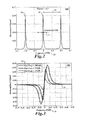
- FIGURE 2 shows a resonance signal as the laser is scanned over a frequency range of about three free spectral ranges (FSRs) (from -1.5 to +1.5 FSR). As shown in FIGURE 2 , three resonance peaks 26 are shown for the assumed parameters above. A resonance full width at half maximum (FWHM) line width 27 is about 3.8% of a free spectral range (FSR) 28, which is the frequency separation of the two resonance peaks 26, corresponding to resonator finesse of 26.3.
- FSRs free spectral ranges
- a demodulated first harmonic signal 30 is shown as a function of laser detuned frequency from a resonance (in units of FSR, i.e. 20 MHz) 29 for several input light modulation frequencies (20, 70 and 200 kHz) 36, but at a fixed modulation amplitude.
- the slopes of the demodulated first harmonic signal 30 i.e. the sensitivity
- a normalized sensitivity is defined as the slope of this demodulated first harmonic signal 30 in units of intensity change (normalized to input light power) per MHz of laser frequency detuning from the resonance peak 26.
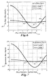
- the dependence of gyro sensitivity 32 is plotted as a function of phase modulation amplitude M34 (in unit of radians) for several modulation frequencies 36, e.g. 20, 70, 200, 300 and 400 kHz.
- modulation frequencies 36 e.g. 20, 70, 200, 300 and 400 kHz.
- modulation amplitude 34 that maximizes the gyro sensitivity 32.
- the plot shows that maximum achievable sensitivities 38 are different for different modulation frequencies 36.
- the gyro sensitivities 32 are plotted versus frequency modulation amplitude (half of peak-to-peak frequency excursion) 39 in units of resonance FWHM (shown in FIGURE 2 ) instead of phase modulation amplitude in units of radians.
- FWHM resonance FWHM
- the maximum achievable sensitivity 38 is reached when the frequency modulation amplitude 39 is about 40% of FWHM.
- the modulation frequency 36 increases from 200 to 300 and 400 kHz, the optimum frequency modulation amplitude 39 also increases from 45% to 65% and 100% of resonance FWHM.
- the disclosed model predicts an in-phase bias error 40 and a quadrature bias error 41 produced by modulator intensity modulation due to polarization cross-coupling.
- phase modulation amplitude 34 at specific values, such as 3.83 and 7.02 radians, for bias reduction may degrade the gyro S/N sensitivity 32 if the modulation frequency 36 is selected arbitrarily.
- finding the optimal modulation frequency 36 is needed once the phase modulation amplitude 34 is set to one of the bias nulling points 46, 48.
- backscattering in the sensing loop may cause CW and CCW lightwaves to reach the same photo detector.
- demodulated signal will contain noise from backscattered light if the input light modulation frequencies are identical in both directions. Therefore it is advantageous to select different modulation frequencies for CW and CCW beams.
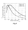
- a modulation frequency separation of a few kHz is typically enough for demodulation electronics to avoid cross-talk effects between different beams. Since the sensitivity peaks (shown in FIGURE 8 ) are relatively broad, there is very little compromise to S/N sensitivity when each input light is modulated within a few kHz of the optimal frequency in FIGURE 8 . The S/N sensitivity can therefore be substantially close to maximum for both CW and CCW light.
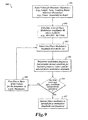
- FIGURE 9 shows a method to carry out an optimization process.
- the basic RFOG parameters such as cavity length, round-trip loss, input/output coupling ratios, laser power and line width 27, are input to a mathematical model.
- the mathematical model is a computer program described above that relates allowable combinations of RFOG parameters to the bias and S/N sensitivity performance of the gyro.
- one amplitude 34 is selected from the set of amplitudes calculated at block 102. For reasons of practical implementation, a low amplitude 34 is likely selected.
- the modulation frequency 36 that maximizes the desired the gyro S/N sensitivity 32 is determined by calculating a response plot (as shown in FIGURE 8 ) for the selected phase modulation amplitude of block 102 and the selected input parameter values for the mathematical model of block 101.
- High S/N sensitivity is generally considered desirable therefore the frequency at which the response plot reaches its peak may be selected.
- the example method 100 determines whether the selected RFOG parameters, phase modulation amplitude and phase modulation frequency achieve the desired reduction in bias and desired sensitivity 32.
- At a block 106 at least one of the gyro input parameters, e.g. input/output coupling ratio, is varied from the value originally used in the mathematical model of block 101.
- the mathematical model relating the RFOG parameters to its sensitivity is recalculated with the newly varied value or values.
- either the same or a different amplitude 34 is selected at block 103.
- response plots are updated according to the new RFOG parameters and the selected phase modulation amplitude 34 so that a new phase modulation frequency can be determined that provides the desired RFOG S/N sensitivity.
- Blocks 103 to 106 can be repeated as many times as necessary until the resulting RFOG design or operation achieves the desired reduction in bias and the desired gyro sensitivity 32.
- phase modulation amplitude and frequency values are applied to the phase modulator 13 of the RFOG 10.
- the selecting and optimizing process highlighted in this invention is by no means limited to occurring during the RFOG design process or though the use of modeling tools. Optimization of the modulation amplitude and frequency of the input beam can be completed during practical operation of the gyro. Servo electronics can be used to dynamically adjust the modulation of the input beam in search of the desired sensitivity and minimum bias error.
Landscapes
- Physics & Mathematics (AREA)
- Engineering & Computer Science (AREA)
- Optics & Photonics (AREA)
- Electromagnetism (AREA)
- Power Engineering (AREA)
- General Physics & Mathematics (AREA)
- Radar, Positioning & Navigation (AREA)
- Remote Sensing (AREA)
- Gyroscopes (AREA)
Applications Claiming Priority (1)
| Application Number | Priority Date | Filing Date | Title |
|---|---|---|---|
| US12/540,175 US8085407B2 (en) | 2009-08-12 | 2009-08-12 | Resonator optical gyroscope having input beam modulation optimized for high sensitivity and low bias |
Publications (3)
| Publication Number | Publication Date |
|---|---|
| EP2293014A2 true EP2293014A2 (de) | 2011-03-09 |
| EP2293014A3 EP2293014A3 (de) | 2011-05-11 |
| EP2293014B1 EP2293014B1 (de) | 2019-03-20 |
Family
ID=43037729
Family Applications (1)
| Application Number | Title | Priority Date | Filing Date |
|---|---|---|---|
| EP10171309.7A Not-in-force EP2293014B1 (de) | 2009-08-12 | 2010-07-29 | Optisches Resonatorgyroskop mit Eingabestrahlmodulation, die für eine hohe Empfindlichkeit und niedrigen Nullratenfehler optimiert ist |
Country Status (3)
| Country | Link |
|---|---|
| US (1) | US8085407B2 (de) |
| EP (1) | EP2293014B1 (de) |
| JP (1) | JP5629156B2 (de) |
Cited By (2)
| Publication number | Priority date | Publication date | Assignee | Title |
|---|---|---|---|---|
| EP3401641A1 (de) * | 2017-05-10 | 2018-11-14 | Honeywell International Inc. | Systeme und verfahren für dynamischen bias-offset-betrieb in einem resonator-glasfasergyroskop |
| US10175047B2 (en) | 2017-05-10 | 2019-01-08 | Honeywell International Inc. | Systems and methods for dynamic bias offset operation in resonator fiber optic gyroscope |
Families Citing this family (16)
| Publication number | Priority date | Publication date | Assignee | Title |
|---|---|---|---|---|
| DE102011081947A1 (de) * | 2011-09-01 | 2013-03-07 | Robert Bosch Gmbh | Sensoranordnung für ein Fahrzeug und Betriebsverfahren für eine Sensoranordnung in einem Fahrzeug |
| US8976364B2 (en) | 2011-10-05 | 2015-03-10 | The Trustees Of The Stevens Institute Of Technology | Optical gyroscope |
| CN102435186B (zh) * | 2011-11-28 | 2013-10-16 | 北京大学 | 一种光纤陀螺的数字信号处理方法、装置及光纤陀螺仪 |
| CN102519445B (zh) * | 2011-12-07 | 2013-12-18 | 浙江大学 | 基于数字相位斜波移频技术的谐振式光学陀螺 |
| US8659760B2 (en) * | 2012-04-12 | 2014-02-25 | Honeywell International Inc. | Resonator fiber optic gyroscope utilizing laser frequency combs |
| US8947671B2 (en) | 2013-02-22 | 2015-02-03 | Honeywell International Inc. | Method and system for detecting optical ring resonator resonance frequencies and free spectral range to reduce the number of lasers in a resonator fiber optic gyroscope |
| CN103353389B (zh) * | 2013-06-21 | 2015-09-30 | 天津大学 | 一种频域干涉谱解调方法 |
| US9001336B1 (en) | 2013-10-07 | 2015-04-07 | Honeywell International Inc. | Methods and apparatus of tracking/locking resonator free spectral range and its application in resonator fiber optic gyroscope |
| WO2015057795A1 (en) * | 2013-10-15 | 2015-04-23 | Coriant Advanced Technology, LLC | Operation and stabilization of mod-mux wdm transmitters based on silicon microrings |
| US9097526B1 (en) | 2014-01-17 | 2015-08-04 | Honeywell International Inc. | Systems and methods for a polarization matched resonator fiber optic gyroscope |
| FR3038785B1 (fr) * | 2015-07-10 | 2017-08-04 | Commissariat Energie Atomique | Laser injecte et procede de generation d'impulsions laser multimode longitudinal |
| CN108489647B (zh) * | 2018-01-16 | 2020-10-02 | 天津大学 | 一种解调保偏光纤中动态应力频率的方法 |
| CN108489640B (zh) * | 2018-01-17 | 2020-10-02 | 天津大学 | 一种基于白光干涉的分布式动态应力频率测量方法 |
| CN109631871B (zh) * | 2018-12-09 | 2021-03-09 | 西安航天精密机电研究所 | 一种抑制光纤陀螺仪交叉耦合的随机调制及解调方法 |
| CN110530355B (zh) * | 2019-08-26 | 2020-12-29 | 北京航空航天大学 | 用于集成光波导陀螺谐振频率跟踪的高带宽信号检测方法 |
| CN115962768B (zh) * | 2023-03-16 | 2023-06-06 | 中国人民解放军国防科技大学 | 一种谐振子闭环激励相位移动控制方法、装置及设备 |
Family Cites Families (5)
| Publication number | Priority date | Publication date | Assignee | Title |
|---|---|---|---|---|
| US5296912A (en) * | 1992-01-16 | 1994-03-22 | Honeywell Inc. | RFOG rotation rate error reducer having resonator mode symmetrization |
| US5469257A (en) | 1993-11-24 | 1995-11-21 | Honeywell Inc. | Fiber optic gyroscope output noise reducer |
| US5781300A (en) * | 1996-10-31 | 1998-07-14 | Honeywell Inc. | Backscatter error reducer for interferometric fiber optic gyroscope |
| US6175410B1 (en) | 1998-12-17 | 2001-01-16 | Honeywell Inc. | Fiber optic gyroscope having modulated suppression of co-propagating and counter-propagating polarization errors |
| US7777889B2 (en) * | 2008-08-07 | 2010-08-17 | Honeywell International Inc. | Bias-instability reduction in fiber optic gyroscopes |
-
2009
- 2009-08-12 US US12/540,175 patent/US8085407B2/en active Active
-
2010
- 2010-07-29 EP EP10171309.7A patent/EP2293014B1/de not_active Not-in-force
- 2010-08-04 JP JP2010175379A patent/JP5629156B2/ja not_active Expired - Fee Related
Non-Patent Citations (1)
| Title |
|---|
| None |
Cited By (2)
| Publication number | Priority date | Publication date | Assignee | Title |
|---|---|---|---|---|
| EP3401641A1 (de) * | 2017-05-10 | 2018-11-14 | Honeywell International Inc. | Systeme und verfahren für dynamischen bias-offset-betrieb in einem resonator-glasfasergyroskop |
| US10175047B2 (en) | 2017-05-10 | 2019-01-08 | Honeywell International Inc. | Systems and methods for dynamic bias offset operation in resonator fiber optic gyroscope |
Also Published As
| Publication number | Publication date |
|---|---|
| EP2293014A3 (de) | 2011-05-11 |
| US8085407B2 (en) | 2011-12-27 |
| JP5629156B2 (ja) | 2014-11-19 |
| EP2293014B1 (de) | 2019-03-20 |
| US20110037985A1 (en) | 2011-02-17 |
| JP2011039049A (ja) | 2011-02-24 |
Similar Documents
| Publication | Publication Date | Title |
|---|---|---|
| EP2293014B1 (de) | Optisches Resonatorgyroskop mit Eingabestrahlmodulation, die für eine hohe Empfindlichkeit und niedrigen Nullratenfehler optimiert ist | |
| US8274659B2 (en) | Resonator fiber optic gyroscopes with reduced rotation rate instability from back reflections | |
| JP4818979B2 (ja) | 外部共振器ビーム発生器を備える光共振器ジャイロ | |
| JP5096858B2 (ja) | 光学式共振器ジャイロスコープ、および共振非対称誤差を低減するための方法 | |
| EP0576663B1 (de) | Symmetrierung von Resonatorbetriebsarten | |
| EP0830570B1 (de) | Eigenfrequenznachlaufanordnung für faseroptische sensorspule | |
| US20150022818A1 (en) | Laser-driven optical gyroscope with push-pull modulation | |
| EP1044354B1 (de) | Faseroptischer kreisel | |
| EP0730725A1 (de) | Reduzierung von optischem rauschen | |
| EP2226612B1 (de) | Hohlraumlängenmodulation in faseroptischen Resonator-Gyroskopen | |
| US6801319B2 (en) | Symmetrical depolarized fiber optic gyroscope | |
| JP2863009B2 (ja) | 共振器光ファイバ・ジャイロスコープのカー効果誤差の削減 | |
| JP2010038906A (ja) | 光ファイバジャイロスコープにおけるバイアス不安定性の低減 | |
| JP2779704B2 (ja) | スペクトル変化系誤差の制御 | |
| EP0935738B1 (de) | Rücksteuerungs-fehlerreduktion in interferometrischen optischen glasfasergyroskopen | |
| EP0990117B1 (de) | Faseroptischer kreisel mit schwingungsfehlerkompensation | |
| US9644966B2 (en) | Integrated optic circuit with waveguides stitched at supplementary angles for reducing coherent backscatter | |
| EP0830569B1 (de) | Optische leistungsstabilisierung für interferometrisches optisches glasfaser-gyroskop | |
| Qiu et al. | Performance of resonator fiber optic gyroscope using external-cavity laser stabilization and optical filtering | |
| Sanders et al. | Improvements of compact resonator fiber optic gyroscopes | |
| Strandjord et al. | Resonator fiber optic gyro progress including observation of navigation grade angle random walk | |
| Chamoun | A laser-driven fiber optic gyroscope for inertial navigation of aircraft | |
| Nasiri-Avanaki et al. | Comparative Assessment on the performance of Open-loop and Closed-loop IFOGs | |
| CN220649542U (zh) | 集成光学芯片及光学陀螺仪 | |
| Terrel | Rotation sensing with optical ring resonators |
Legal Events
| Date | Code | Title | Description |
|---|---|---|---|
| PUAI | Public reference made under article 153(3) epc to a published international application that has entered the european phase |
Free format text: ORIGINAL CODE: 0009012 |
|
| 17P | Request for examination filed |
Effective date: 20100729 |
|
| AK | Designated contracting states |
Kind code of ref document: A2 Designated state(s): AL AT BE BG CH CY CZ DE DK EE ES FI FR GB GR HR HU IE IS IT LI LT LU LV MC MK MT NL NO PL PT RO SE SI SK SM TR |
|
| AX | Request for extension of the european patent |
Extension state: BA ME RS |
|
| PUAL | Search report despatched |
Free format text: ORIGINAL CODE: 0009013 |
|
| AK | Designated contracting states |
Kind code of ref document: A3 Designated state(s): AL AT BE BG CH CY CZ DE DK EE ES FI FR GB GR HR HU IE IS IT LI LT LU LV MC MK MT NL NO PL PT RO SE SI SK SM TR |
|
| AX | Request for extension of the european patent |
Extension state: BA ME RS |
|
| RAP1 | Party data changed (applicant data changed or rights of an application transferred) |
Owner name: HONEYWELL INTERNATIONAL INC. |
|
| STAA | Information on the status of an ep patent application or granted ep patent |
Free format text: STATUS: EXAMINATION IS IN PROGRESS |
|
| 17Q | First examination report despatched |
Effective date: 20170608 |
|
| GRAP | Despatch of communication of intention to grant a patent |
Free format text: ORIGINAL CODE: EPIDOSNIGR1 |
|
| STAA | Information on the status of an ep patent application or granted ep patent |
Free format text: STATUS: GRANT OF PATENT IS INTENDED |
|
| INTG | Intention to grant announced |
Effective date: 20181017 |
|
| GRAS | Grant fee paid |
Free format text: ORIGINAL CODE: EPIDOSNIGR3 |
|
| GRAA | (expected) grant |
Free format text: ORIGINAL CODE: 0009210 |
|
| STAA | Information on the status of an ep patent application or granted ep patent |
Free format text: STATUS: THE PATENT HAS BEEN GRANTED |
|
| AK | Designated contracting states |
Kind code of ref document: B1 Designated state(s): AL AT BE BG CH CY CZ DE DK EE ES FI FR GB GR HR HU IE IS IT LI LT LU LV MC MK MT NL NO PL PT RO SE SI SK SM TR |
|
| REG | Reference to a national code |
Ref country code: GB Ref legal event code: FG4D |
|
| REG | Reference to a national code |
Ref country code: CH Ref legal event code: EP |
|
| REG | Reference to a national code |
Ref country code: DE Ref legal event code: R096 Ref document number: 602010057655 Country of ref document: DE |
|
| REG | Reference to a national code |
Ref country code: AT Ref legal event code: REF Ref document number: 1111011 Country of ref document: AT Kind code of ref document: T Effective date: 20190415 |
|
| REG | Reference to a national code |
Ref country code: IE Ref legal event code: FG4D |
|
| REG | Reference to a national code |
Ref country code: NL Ref legal event code: MP Effective date: 20190320 |
|
| PG25 | Lapsed in a contracting state [announced via postgrant information from national office to epo] |
Ref country code: LT Free format text: LAPSE BECAUSE OF FAILURE TO SUBMIT A TRANSLATION OF THE DESCRIPTION OR TO PAY THE FEE WITHIN THE PRESCRIBED TIME-LIMIT Effective date: 20190320 Ref country code: FI Free format text: LAPSE BECAUSE OF FAILURE TO SUBMIT A TRANSLATION OF THE DESCRIPTION OR TO PAY THE FEE WITHIN THE PRESCRIBED TIME-LIMIT Effective date: 20190320 Ref country code: SE Free format text: LAPSE BECAUSE OF FAILURE TO SUBMIT A TRANSLATION OF THE DESCRIPTION OR TO PAY THE FEE WITHIN THE PRESCRIBED TIME-LIMIT Effective date: 20190320 Ref country code: NO Free format text: LAPSE BECAUSE OF FAILURE TO SUBMIT A TRANSLATION OF THE DESCRIPTION OR TO PAY THE FEE WITHIN THE PRESCRIBED TIME-LIMIT Effective date: 20190620 |
|
| REG | Reference to a national code |
Ref country code: LT Ref legal event code: MG4D |
|
| PG25 | Lapsed in a contracting state [announced via postgrant information from national office to epo] |
Ref country code: BG Free format text: LAPSE BECAUSE OF FAILURE TO SUBMIT A TRANSLATION OF THE DESCRIPTION OR TO PAY THE FEE WITHIN THE PRESCRIBED TIME-LIMIT Effective date: 20190620 Ref country code: HR Free format text: LAPSE BECAUSE OF FAILURE TO SUBMIT A TRANSLATION OF THE DESCRIPTION OR TO PAY THE FEE WITHIN THE PRESCRIBED TIME-LIMIT Effective date: 20190320 Ref country code: GR Free format text: LAPSE BECAUSE OF FAILURE TO SUBMIT A TRANSLATION OF THE DESCRIPTION OR TO PAY THE FEE WITHIN THE PRESCRIBED TIME-LIMIT Effective date: 20190621 Ref country code: LV Free format text: LAPSE BECAUSE OF FAILURE TO SUBMIT A TRANSLATION OF THE DESCRIPTION OR TO PAY THE FEE WITHIN THE PRESCRIBED TIME-LIMIT Effective date: 20190320 Ref country code: NL Free format text: LAPSE BECAUSE OF FAILURE TO SUBMIT A TRANSLATION OF THE DESCRIPTION OR TO PAY THE FEE WITHIN THE PRESCRIBED TIME-LIMIT Effective date: 20190320 |
|
| REG | Reference to a national code |
Ref country code: AT Ref legal event code: MK05 Ref document number: 1111011 Country of ref document: AT Kind code of ref document: T Effective date: 20190320 |
|
| PG25 | Lapsed in a contracting state [announced via postgrant information from national office to epo] |
Ref country code: CZ Free format text: LAPSE BECAUSE OF FAILURE TO SUBMIT A TRANSLATION OF THE DESCRIPTION OR TO PAY THE FEE WITHIN THE PRESCRIBED TIME-LIMIT Effective date: 20190320 Ref country code: IT Free format text: LAPSE BECAUSE OF FAILURE TO SUBMIT A TRANSLATION OF THE DESCRIPTION OR TO PAY THE FEE WITHIN THE PRESCRIBED TIME-LIMIT Effective date: 20190320 Ref country code: RO Free format text: LAPSE BECAUSE OF FAILURE TO SUBMIT A TRANSLATION OF THE DESCRIPTION OR TO PAY THE FEE WITHIN THE PRESCRIBED TIME-LIMIT Effective date: 20190320 Ref country code: SK Free format text: LAPSE BECAUSE OF FAILURE TO SUBMIT A TRANSLATION OF THE DESCRIPTION OR TO PAY THE FEE WITHIN THE PRESCRIBED TIME-LIMIT Effective date: 20190320 Ref country code: ES Free format text: LAPSE BECAUSE OF FAILURE TO SUBMIT A TRANSLATION OF THE DESCRIPTION OR TO PAY THE FEE WITHIN THE PRESCRIBED TIME-LIMIT Effective date: 20190320 Ref country code: EE Free format text: LAPSE BECAUSE OF FAILURE TO SUBMIT A TRANSLATION OF THE DESCRIPTION OR TO PAY THE FEE WITHIN THE PRESCRIBED TIME-LIMIT Effective date: 20190320 Ref country code: PT Free format text: LAPSE BECAUSE OF FAILURE TO SUBMIT A TRANSLATION OF THE DESCRIPTION OR TO PAY THE FEE WITHIN THE PRESCRIBED TIME-LIMIT Effective date: 20190720 Ref country code: AL Free format text: LAPSE BECAUSE OF FAILURE TO SUBMIT A TRANSLATION OF THE DESCRIPTION OR TO PAY THE FEE WITHIN THE PRESCRIBED TIME-LIMIT Effective date: 20190320 |
|
| PG25 | Lapsed in a contracting state [announced via postgrant information from national office to epo] |
Ref country code: PL Free format text: LAPSE BECAUSE OF FAILURE TO SUBMIT A TRANSLATION OF THE DESCRIPTION OR TO PAY THE FEE WITHIN THE PRESCRIBED TIME-LIMIT Effective date: 20190320 Ref country code: SM Free format text: LAPSE BECAUSE OF FAILURE TO SUBMIT A TRANSLATION OF THE DESCRIPTION OR TO PAY THE FEE WITHIN THE PRESCRIBED TIME-LIMIT Effective date: 20190320 |
|
| PG25 | Lapsed in a contracting state [announced via postgrant information from national office to epo] |
Ref country code: IS Free format text: LAPSE BECAUSE OF FAILURE TO SUBMIT A TRANSLATION OF THE DESCRIPTION OR TO PAY THE FEE WITHIN THE PRESCRIBED TIME-LIMIT Effective date: 20190720 Ref country code: AT Free format text: LAPSE BECAUSE OF FAILURE TO SUBMIT A TRANSLATION OF THE DESCRIPTION OR TO PAY THE FEE WITHIN THE PRESCRIBED TIME-LIMIT Effective date: 20190320 |
|
| REG | Reference to a national code |
Ref country code: DE Ref legal event code: R097 Ref document number: 602010057655 Country of ref document: DE |
|
| PLBE | No opposition filed within time limit |
Free format text: ORIGINAL CODE: 0009261 |
|
| STAA | Information on the status of an ep patent application or granted ep patent |
Free format text: STATUS: NO OPPOSITION FILED WITHIN TIME LIMIT |
|
| PG25 | Lapsed in a contracting state [announced via postgrant information from national office to epo] |
Ref country code: DK Free format text: LAPSE BECAUSE OF FAILURE TO SUBMIT A TRANSLATION OF THE DESCRIPTION OR TO PAY THE FEE WITHIN THE PRESCRIBED TIME-LIMIT Effective date: 20190320 |
|
| 26N | No opposition filed |
Effective date: 20200102 |
|
| PG25 | Lapsed in a contracting state [announced via postgrant information from national office to epo] |
Ref country code: SI Free format text: LAPSE BECAUSE OF FAILURE TO SUBMIT A TRANSLATION OF THE DESCRIPTION OR TO PAY THE FEE WITHIN THE PRESCRIBED TIME-LIMIT Effective date: 20190320 Ref country code: MC Free format text: LAPSE BECAUSE OF FAILURE TO SUBMIT A TRANSLATION OF THE DESCRIPTION OR TO PAY THE FEE WITHIN THE PRESCRIBED TIME-LIMIT Effective date: 20190320 |
|
| REG | Reference to a national code |
Ref country code: CH Ref legal event code: PL |
|
| GBPC | Gb: european patent ceased through non-payment of renewal fee |
Effective date: 20190729 |
|
| PG25 | Lapsed in a contracting state [announced via postgrant information from national office to epo] |
Ref country code: TR Free format text: LAPSE BECAUSE OF FAILURE TO SUBMIT A TRANSLATION OF THE DESCRIPTION OR TO PAY THE FEE WITHIN THE PRESCRIBED TIME-LIMIT Effective date: 20190320 |
|
| REG | Reference to a national code |
Ref country code: BE Ref legal event code: MM Effective date: 20190731 |
|
| PG25 | Lapsed in a contracting state [announced via postgrant information from national office to epo] |
Ref country code: GB Free format text: LAPSE BECAUSE OF NON-PAYMENT OF DUE FEES Effective date: 20190729 |
|
| PG25 | Lapsed in a contracting state [announced via postgrant information from national office to epo] |
Ref country code: LI Free format text: LAPSE BECAUSE OF NON-PAYMENT OF DUE FEES Effective date: 20190731 Ref country code: CH Free format text: LAPSE BECAUSE OF NON-PAYMENT OF DUE FEES Effective date: 20190731 Ref country code: LU Free format text: LAPSE BECAUSE OF NON-PAYMENT OF DUE FEES Effective date: 20190729 Ref country code: BE Free format text: LAPSE BECAUSE OF NON-PAYMENT OF DUE FEES Effective date: 20190731 |
|
| PG25 | Lapsed in a contracting state [announced via postgrant information from national office to epo] |
Ref country code: IE Free format text: LAPSE BECAUSE OF NON-PAYMENT OF DUE FEES Effective date: 20190729 |
|
| PGFP | Annual fee paid to national office [announced via postgrant information from national office to epo] |
Ref country code: DE Payment date: 20200729 Year of fee payment: 11 Ref country code: FR Payment date: 20200728 Year of fee payment: 11 |
|
| PG25 | Lapsed in a contracting state [announced via postgrant information from national office to epo] |
Ref country code: CY Free format text: LAPSE BECAUSE OF FAILURE TO SUBMIT A TRANSLATION OF THE DESCRIPTION OR TO PAY THE FEE WITHIN THE PRESCRIBED TIME-LIMIT Effective date: 20190320 |
|
| PG25 | Lapsed in a contracting state [announced via postgrant information from national office to epo] |
Ref country code: HU Free format text: LAPSE BECAUSE OF FAILURE TO SUBMIT A TRANSLATION OF THE DESCRIPTION OR TO PAY THE FEE WITHIN THE PRESCRIBED TIME-LIMIT; INVALID AB INITIO Effective date: 20100729 Ref country code: MT Free format text: LAPSE BECAUSE OF FAILURE TO SUBMIT A TRANSLATION OF THE DESCRIPTION OR TO PAY THE FEE WITHIN THE PRESCRIBED TIME-LIMIT Effective date: 20190320 |
|
| REG | Reference to a national code |
Ref country code: DE Ref legal event code: R119 Ref document number: 602010057655 Country of ref document: DE |
|
| PG25 | Lapsed in a contracting state [announced via postgrant information from national office to epo] |
Ref country code: DE Free format text: LAPSE BECAUSE OF NON-PAYMENT OF DUE FEES Effective date: 20220201 |
|
| PG25 | Lapsed in a contracting state [announced via postgrant information from national office to epo] |
Ref country code: FR Free format text: LAPSE BECAUSE OF NON-PAYMENT OF DUE FEES Effective date: 20210731 |
|
| PG25 | Lapsed in a contracting state [announced via postgrant information from national office to epo] |
Ref country code: MK Free format text: LAPSE BECAUSE OF FAILURE TO SUBMIT A TRANSLATION OF THE DESCRIPTION OR TO PAY THE FEE WITHIN THE PRESCRIBED TIME-LIMIT Effective date: 20190320 |
|
| P01 | Opt-out of the competence of the unified patent court (upc) registered |
Effective date: 20230525 |