EP2292945B1 - Frein à disque doté d'un accouplement à patinage pour le dispositif de réglage - Google Patents
Frein à disque doté d'un accouplement à patinage pour le dispositif de réglage Download PDFInfo
- Publication number
- EP2292945B1 EP2292945B1 EP10174631.1A EP10174631A EP2292945B1 EP 2292945 B1 EP2292945 B1 EP 2292945B1 EP 10174631 A EP10174631 A EP 10174631A EP 2292945 B1 EP2292945 B1 EP 2292945B1
- Authority
- EP
- European Patent Office
- Prior art keywords
- sleeve
- clutch
- brake
- polygonal
- disc
- Prior art date
- Legal status (The legal status is an assumption and is not a legal conclusion. Google has not performed a legal analysis and makes no representation as to the accuracy of the status listed.)
- Not-in-force
Links
Images


Classifications
-
- F—MECHANICAL ENGINEERING; LIGHTING; HEATING; WEAPONS; BLASTING
- F16—ENGINEERING ELEMENTS AND UNITS; GENERAL MEASURES FOR PRODUCING AND MAINTAINING EFFECTIVE FUNCTIONING OF MACHINES OR INSTALLATIONS; THERMAL INSULATION IN GENERAL
- F16D—COUPLINGS FOR TRANSMITTING ROTATION; CLUTCHES; BRAKES
- F16D65/00—Parts or details
- F16D65/38—Slack adjusters
- F16D65/40—Slack adjusters mechanical
- F16D65/52—Slack adjusters mechanical self-acting in one direction for adjusting excessive play
- F16D65/56—Slack adjusters mechanical self-acting in one direction for adjusting excessive play with screw-thread and nut
Definitions
- the invention relates to a disc brake according to the preamble of claim 1.
- Such a brake is from the EP 0 566 008 A1 known.
- the vehicle brake in question is designed especially for commercial vehicles.
- the brake pads are heavily loaded due to the high braked masses.
- the wear of the brake pads is therefore correspondingly high.
- the adjusting device is designed so that according to the wear of the brake pads an adjustment takes place.
- the adjusting device When changing the brake linings, it may be due to the design of the adjusting device to exceed an allowable torque of the internal mechanism. This torque is initiated via the manual reset device or the adjusting spindle. If a certain torque is exceeded, the slip clutch responds to the adjustment spindle, which can also be referred to as a safety or overload clutch. In the disk brake in question, it has the task of securing the internal components of the adjuster against damage or destruction.
- Slip clutches are well known. In terms of function, friction clutches are distinguished by a constant contact force, which however can also be adjustable. According to another design so-called multi-plate clutches are used. These slats are made of steel, but they may also be provided with friction linings. The contact pressure is generated by suitable springs.
- EP 0 566 008 A1 describes a pneumatic disc brake with a brake disc comprising a brake caliper, on the side of a clamping device is arranged.
- the application device acts via at least one adjusting spindle and a thrust piece seated on its brake disk-side end on a brake shoe displaceable on the application side in the brake caliper with respect to the brake disk.
- An adjusting device is rotatably coupled to the adjusting spindle to keep constant due to pad wear changing clearance.
- the adjusting device is coupled to an externally operable rotary drive device, by means of which the adjusting spindle can be returned to its initial position.
- the rotary drive device is provided with a separating device, for example a predetermined breaking point or a slip clutch, in order to prevent a malfunction of the brake in the event of an improper brake pad replacement when a specific limit torque is exceeded.
- JP 10 047326 A describes a screw with a built-in torque limiter.
- a threaded threaded shank is provided with a disc having circumferentially disposed tooth flanks with the tooth flanks facing away from the free end of the screw shank.
- a second screw shaft is arranged with a smaller diameter than the former and with thread, which is guided by a hexagonal screw head.
- the screw head has on its underside a corresponding with the teeth of the disc of the screw shaft and engaging in this toothing.
- the screw head is axially movable.
- axial springs eg disc springs, are placed within the screw head and biased and secured with a nut on the second screw shaft for setting a limit torque. As a result, the toothing is held in engagement.
- the toothing is disengaged by axial movement of the screw head against the force of the preloaded axial spring and limits the torque.
- US 2006/024142 A1 describes a threaded bolt with torque limiter.
- the threaded bolt has a cylindrical head which is inserted through an opening in a bottom of a corrugated cylindrical sleeve.
- the sleeve surrounds the head of the threaded bolt and is coupled to the head via a square bar in pin form.
- the square bar is inserted into holes in the cylindrical wall of the sleeve at its side facing away from the threaded bolt, open side.
- an annular, resilient in the axial direction ramp is rotatably applied whose circumferential angle is less than 360 °, so that between a resilient, upstanding end and a fixed end, a distance is provided, which corresponds to the cross section of the square bar, the distance something is formed larger.
- the square bar contacts the surface of the resilient ramp.
- the spring force of the resilient ramp the underside of the square bar is pressed against the resilient ramp, wherein the bottom of the sleeve, on which the head rests, forms an axial stop.
- the spring force of the resilient ramp determines the friction between the square bar and the surface of the resilient ramp.
- the threaded bolt is rotated by the friction between the bottom of the square bar and the surface of the resilient ramp.
- the square bar slips in a pivotal motion relative to the resilient ramp to the end thereof, which is spaced from the stationary end, and locks with a clicking sound into the distance between these ends , This signal is acoustically signaled to the user that the limit torque has been reached. Further rotation is possible because the square bar contacts the fixed end. When turning back, the square bar contacts the resilient end of the ramp and thus exerts a torque on the threaded bolt for unscrewing.
- the present invention has for its object to make an improved disc brake of the type described in more detail with an adjuster so that the slip clutches can be produced inexpensively without the use of springs, but it is ensured that even after several overloads the slip clutch neither destroyed is still worn.
- the stated object is achieved in that the coupling halves are coupled together by at least one elastically deformable in the elastic range of the material, designed as a pull rod or torsion bar reset rod.
- each return rod is a tensile bar elastically deformable by tensile forces.
- the coupling halves must then be designed so that they can move when exceeding a certain torque in the axial direction.
- the slip clutch is formed from a polygonal sleeve and a cup-shaped coupling sleeve, wherein the mutually facing end faces with in each case one Ring face lying spur gears are provided, which engage with each other and are wedge-shaped.
- the wedge angle is relatively small, so that when a certain torque is exceeded, the axial displacement of a coupling half is correspondingly low. As soon as the serrations mesh again, the elastic deformation of the tension rod is released.
- the tension rod extends over the height of the polygonal sleeve and is arranged centrally in this and at the end face facing away from the end portion is firmly inserted into the frontal wall of the polygonal sleeve.
- the greatest possible length of the tension rod is achieved, so that the elastic deformation is correspondingly high.
- the end of the tension rod is provided with a head which engages behind the end wall of the coupling sleeve.
- the spur toothing consists of inclined flanks and approximately perpendicular flanks. When exceeding a certain torque, the inclined flanks slide on each other and cause the axial displacement of a coupling half.
- the coupling sleeve is provided on the side facing away from the serrations on the inside with a profiling formed by longitudinal webs and longitudinal grooves.
- this coupling sleeve can be coupled with a counterpart.
- the adjustment of the slip clutch is made by turning the polygonal sleeve by means of a suitable tool.
- the polygonal sleeve is a hexagonal sleeve.
- the return rod is a torsion bar which can be rotated or twisted by torsional and / or bending forces.
- This torsion bar is in turn firmly clamped with one end and designed so that when exceeding a certain torque of this torsion bar a small little is deformed, so that between the two coupling halves, a relative movement is performed.
- the torsion bar is designed T-shaped in longitudinal section and that it is firmly clamped in the wall of the polygonal sleeve facing away from the coupling sleeve. This takes place, for example, by means of a recess, adapted in one of the cross-sectional shape of the torsion bar, of the end wall of the polygonal sleeve.
- a recess adapted in one of the cross-sectional shape of the torsion bar, of the end wall of the polygonal sleeve.
- the coupling bush is expediently provided in the connecting region of the two coupling halves or bushes with an internal toothing.
- the torsion bar engages with its transversely to the central longitudinal axis of the coupling sleeve locking ridge in this toothing.
- a rotation of the coupling sleeve relative to the hexagonal sleeve takes place.
- the adjustment of the torque is again through the polygonal sleeve, which is twisted.
- FIG. 1 shows that a mounted on an axis, not shown axle of a commercial vehicle brake disc 1 is arranged in a caliper 2. On both sides of the brake disc 1, the brake pads 3, 4 are mounted.
- the disc brake is also preferably equipped with a crossbeam 5, in which two parallel and spaced-apart adjusting spindles 6, 7 are mounted.
- the reference numeral 8 the entire application device is designated.
- the two adjusting spindles 6, 7 are synchronously coupled to each other via a synchronization device, in the illustrated embodiment by a chain drive 9.
- a complete disc brake is for example in the EP 0 566 008 A1 described.
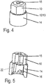
- the slip clutch is located at one end of one of the adjusting spindles, so that it is accessible from the outside for turning back during the lining change. Thereafter, it consists essentially of a coupling half forming polygonal sleeve 10, a further coupling half forming coupling sleeve 14 and a connecting the two parts tie rod 15th
- the polygonal sleeve 10 and the coupling sleeve 14 is provided at one end face with a respective spur toothing 12, 13, which according to the FIG. 4 engage each other.
- the teeth are wedge-shaped, the wedge angle is relatively low and only a few degrees. especially the FIG.
- FIG. 5 shows that the polygonal sleeve 10 are connected to the coupling sleeve 14 via a return rod in the form of a tie rod 15 with each other.
- This tension rod 15 passes through the polygonal sleeve 10 and is equipped with a head which abuts the outside of the end face of the polygonal sleeve 10. On the opposite side, a head is also formed, which engages behind the end face of the coupling sleeve 14.
- the spur gears 12, 13 are designed so that when a certain torque is exceeded, the coupling sleeve 14 is rotated. Characterized the tension rod 15 is stretched and causes the spur gears 12, 13 again lie flat against each other when a tooth is skipped. For this purpose, the tension rod 15 brings a restoring force.
- the coupling sleeve 14 is provided at its free, the polygonal sleeve 15 facing away from the end with a profiling 22 to insert therein a corresponding counterpart of the adjusting torque-transmitting.
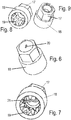
- FIGS. 6 to 11 show a second embodiment of the slip clutch according to the invention.
- the two coupling halves are in turn formed by a polygonal bushing 17 and a coupling sleeve 18. These two sleeves are connected by a reset rod, which is twisted by torsional or bending forces in the elastic range.
- One end of this torsion bar is inserted into a clamping opening 20 of the polygonal sleeve 17.
- This Torsionsstab is T-shaped in longitudinal section and has at the clamping opening 20 opposite End a latching ridge 21, which performs the function of a Kochratschettis.
- the two end regions of this latching web 21 engage in an internal profiling or toothing 19 of the coupling bushing 18.
- This design is particularly evident from the FIGS. 10 and 11 , In this coupling bushing 18 is provided in the free end region with a toothing 19 formed from webs and grooves in order to set up the slip clutch R on a corresponding contour of the adjusting spindle.
- the invention is not limited to the illustrated embodiments. It is essential that when exceeding a predetermined torque, the two coupling halves are rotated against each other, and that by this rotation a tension rod 15 is elongated or a torsion bar is twisted.
- polygon is not meant to be limiting. It includes torque transmission contours of various kinds.
Landscapes
- Engineering & Computer Science (AREA)
- General Engineering & Computer Science (AREA)
- Mechanical Engineering (AREA)
- Braking Arrangements (AREA)
- Mechanical Operated Clutches (AREA)
Claims (6)
- Frein à disque qui comprend un étrier de frein (2) dans lequel un disque de frein (1) et deux garnitures de frein (3, 4) disposées des deux côtés du disque de frein (1) sont montés, et qui, pour la compensation de l'usure des garnitures de frein (3, 4), est équipé d'un dispositif de rattrapage (3, 4) qui présente au moins une broche de rattrapage (6, 7) à laquelle est associé un accouplement à patinage (R) composé de deux moitiés d'accouplement et réagissant lors de la rotation en marche arrière lors du changement de garniture en cas de dépassement d'un couple déterminé,
caractérisé en ce que l'accouplement à patinage (R) se compose d'une douille polygonale (10) et d'une douille d'accouplement (14), et en ce que les faces frontales tournées l'une vers l'autre de la douille polygonale (10) et de la douille d'accouplement (14) présentent respectivement une face annulaire dotée de dentures frontales (12, 13) qui s'engrènent les unes dans les autres, sachant que les dentures frontales (12, 13) sont constituées en forme de coins, sachant que les moitiés d'accouplement (10, 14) sont couplées l'une à l'autre par au moins une barre de traction (15) déformable élastiquement dans la plage d'élasticité du matériau par des efforts de traction, sachant que la barre de traction (15) s'étend au-delà de la hauteur de la douille polygonale (10) et est disposée de manière centrée dans celle-ci, et en ce que la zone opposée à la denture frontale (12, 13) est fermement insérée dans la paroi frontale de la douille polygonale (10),
sachant que la douille d'accouplement (14) est en forme de pot, et les angles de coin sont tels qu'un mouvement relatif entre la douille polygonale (10) et la douille d'accouplement (14) puisse être effectué moyennant un allongement de la barre de traction. - Frein à disque selon la revendication 1, caractérisé en ce que la douille d'accouplement (14) est pourvue d'une denture (19) constituée, du côté opposé à la denture frontale (12, 13), côté intérieur, de nervures longitudinales et de moyeux.
- Frein à disque qui comprend un étrier de frein (2) dans lequel un disque de frein (1) et deux garnitures de frein (3, 4) disposées des deux côtés du disque de frein (1) sont montés, et qui, pour la compensation de l'usure des garnitures de frein (3, 4), est équipé d'un dispositif de rattrapage (3, 4) qui présente au moins une broche de rattrapage (6, 7) à laquelle est associé un accouplement à patinage (R) composé de deux moitiés d'accouplement et réagissant lors de la rotation en marche arrière lors du changement de garniture en cas de dépassement d'un couple déterminé,
caractérisé en ce que l'accouplement à patinage (R) se compose d'une douille polygonale (17) et d'une douille d'accouplement (18) présentant des faces frontales tournées l'une vers l'autre, sachant que les moitiés d'accouplement (17, 18) sont couplées l'une à l'autre par au moins une barre de rotation déformable en rotation ou en torsion dans la plage d'élasticité du matériau par des efforts de torsion et/ou de flexion, sachant que la barre de rotation s'étend au-delà de la hauteur de la douille polygonale (17) et est disposée de manière centrée dans celle-ci, sachant que la barre de rotation présente, dans la zone de la douille d'accouplement (18), une nervure d'encliquetage (21) dont les zones d'extrémité s'engrènent dans une denture intérieure (19) de la douille d'accouplement (18) et exécutent la fonction d'un élément de surencliquetage. - Frein à disque selon la revendication 3, caractérisé en ce que, vue en coupe longitudinale, la barre de rotation est configurée en forme de T, sachant qu'une extrémité est fixée dans la douille polygonale (17).
- Frein à disque selon la revendication 4, caractérisé en ce qu'une ouverture de blocage (20) dans laquelle la zone d'extrémité de la barre de rotation s'engrène est prévue dans la paroi côté frontal de la douille polygonale (17).
- Frein à disque selon l'une ou plusieurs des revendications 3 à 5, caractérisé en ce que la barre de rotation est constituée comme barre plate dans la zone de la douille polygonale (17).
Applications Claiming Priority (1)
| Application Number | Priority Date | Filing Date | Title |
|---|---|---|---|
| DE200910039800 DE102009039800A1 (de) | 2009-09-02 | 2009-09-02 | Scheibenbremse mit Rutschkupplung für die Nachstelleinrichtung |
Publications (2)
| Publication Number | Publication Date |
|---|---|
| EP2292945A1 EP2292945A1 (fr) | 2011-03-09 |
| EP2292945B1 true EP2292945B1 (fr) | 2017-04-12 |
Family
ID=43333129
Family Applications (1)
| Application Number | Title | Priority Date | Filing Date |
|---|---|---|---|
| EP10174631.1A Not-in-force EP2292945B1 (fr) | 2009-09-02 | 2010-08-31 | Frein à disque doté d'un accouplement à patinage pour le dispositif de réglage |
Country Status (2)
| Country | Link |
|---|---|
| EP (1) | EP2292945B1 (fr) |
| DE (1) | DE102009039800A1 (fr) |
Families Citing this family (3)
| Publication number | Priority date | Publication date | Assignee | Title |
|---|---|---|---|---|
| DE102012108672B3 (de) | 2012-09-17 | 2014-02-06 | Knorr-Bremse Systeme für Nutzfahrzeuge GmbH | Nachstelleinrichtung einer Scheibenbremse, eine entsprechende Scheibenbremse und Verfahren zum Betreiben einer Verschleißnachstellvorrichtung einer Scheibenbremse |
| CN106870603B (zh) | 2015-12-10 | 2020-01-14 | 英国美瑞特重型车制动系统有限公司 | 调整器组件 |
| EP3179128A1 (fr) * | 2015-12-10 | 2017-06-14 | Meritor Heavy Vehicle Braking Systems (UK) Limited | Dispositif de rembobinage manuel |
Family Cites Families (5)
| Publication number | Priority date | Publication date | Assignee | Title |
|---|---|---|---|---|
| US3929054A (en) * | 1972-12-01 | 1975-12-30 | Elco Industries Inc | Fastening element adapted for tightening to predetermined torque |
| DE4212405C2 (de) | 1992-04-13 | 2000-02-10 | Knorr Bremse Ag | Druckluftbetätigte Scheibenbremse |
| JPH1047326A (ja) * | 1996-08-01 | 1998-02-17 | Fujitsu Ten Ltd | トルクリミット機構内蔵ねじ |
| US20050008446A1 (en) * | 2003-02-06 | 2005-01-13 | Joe Allen | Torque controlling fastener |
| US20060024142A1 (en) * | 2004-08-02 | 2006-02-02 | Ducret Lucien C | Torque-limiting stud |
-
2009
- 2009-09-02 DE DE200910039800 patent/DE102009039800A1/de not_active Withdrawn
-
2010
- 2010-08-31 EP EP10174631.1A patent/EP2292945B1/fr not_active Not-in-force
Non-Patent Citations (1)
| Title |
|---|
| None * |
Also Published As
| Publication number | Publication date |
|---|---|
| DE102009039800A1 (de) | 2011-03-10 |
| EP2292945A1 (fr) | 2011-03-09 |
Similar Documents
| Publication | Publication Date | Title |
|---|---|---|
| EP2307756B1 (fr) | Dispositif de rattrapage de jeu pour un frein à disque | |
| WO2011113724A1 (fr) | Vis d'entraînement à roulement planétaire | |
| EP3271604A1 (fr) | Frein à disque pour véhicule utilitaire | |
| DE102014017438A1 (de) | Scheibenbremse. insbesondere für Nutzfahrzeuge | |
| DE102005003223B4 (de) | Scheibenbremse mit Nachstelleinrichtung | |
| DE102014017156B3 (de) | Betätigungseinrichtung für eine Innenbackenbremse mit manuell betätigbarer Rückstelleinrichtung | |
| EP2292945B1 (fr) | Frein à disque doté d'un accouplement à patinage pour le dispositif de réglage | |
| DE102008005454B4 (de) | Scheibenbremse mit Rutschkupplung für die Nachstelleinrichtung | |
| EP2055981B1 (fr) | Frein de véhicule | |
| DE102011051073B4 (de) | Vorrichtung zum Nachstellen des verschleißbedingten Lüftspiels bei einer Fahrzeugbremse | |
| EP2636917A1 (fr) | Dispositif de réglage d'usure pour freins à disques | |
| WO2016037934A1 (fr) | Dispositif de rattrapage de jeu pour frein à disque actionné par levier rotatif, et frein à disque pourvu d'un dispositif de rattrapage de jeu | |
| DE102008005455B4 (de) | Scheibenbremse mit Sicherheitskupplung für die Nachstelleinrichtung | |
| EP3779229B1 (fr) | Bague d'accouplement | |
| DE10236832A1 (de) | Druckplattenbaugruppe | |
| DE102013212429A1 (de) | Reibkupplung mit weggesteuerter Verschleißnachstelleinrichtung | |
| DE102004007372B4 (de) | Schraubwerkzeug | |
| EP3436713B1 (fr) | Dispositif de compensation d'usure comprenant une tige filetée fixée au préalable et embrayage | |
| EP3542082B1 (fr) | Dispositif de rattrapage d'usure pour frein à disque | |
| DE102007019440B4 (de) | Scheibenbremse mit Lösespindel für die Nachstelleinrichtung | |
| EP4337877A1 (fr) | Frein à disque muni d'une unité de rattrapage | |
| WO2020002156A1 (fr) | Dispositif de rattrapage permettant le rattrapage de jeu d'un frein à disque, frein à disque et procédé de rattrapage | |
| DE102019130423A1 (de) | Antriebsstrang | |
| EP3807051A1 (fr) | Dispositif limiteur de couple et son procédé d'étalonnage | |
| DE102016116961A1 (de) | Nachsteller für ein Bremssystem |
Legal Events
| Date | Code | Title | Description |
|---|---|---|---|
| PUAI | Public reference made under article 153(3) epc to a published international application that has entered the european phase |
Free format text: ORIGINAL CODE: 0009012 |
|
| AK | Designated contracting states |
Kind code of ref document: A1 Designated state(s): AL AT BE BG CH CY CZ DE DK EE ES FI FR GB GR HR HU IE IS IT LI LT LU LV MC MK MT NL NO PL PT RO SE SI SK SM TR |
|
| AX | Request for extension of the european patent |
Extension state: BA ME RS |
|
| 17P | Request for examination filed |
Effective date: 20110909 |
|
| 17Q | First examination report despatched |
Effective date: 20150603 |
|
| GRAP | Despatch of communication of intention to grant a patent |
Free format text: ORIGINAL CODE: EPIDOSNIGR1 |
|
| INTG | Intention to grant announced |
Effective date: 20161020 |
|
| GRAS | Grant fee paid |
Free format text: ORIGINAL CODE: EPIDOSNIGR3 |
|
| GRAA | (expected) grant |
Free format text: ORIGINAL CODE: 0009210 |
|
| AK | Designated contracting states |
Kind code of ref document: B1 Designated state(s): AL AT BE BG CH CY CZ DE DK EE ES FI FR GB GR HR HU IE IS IT LI LT LU LV MC MK MT NL NO PL PT RO SE SI SK SM TR |
|
| REG | Reference to a national code |
Ref country code: GB Ref legal event code: FG4D Free format text: NOT ENGLISH |
|
| REG | Reference to a national code |
Ref country code: CH Ref legal event code: EP |
|
| REG | Reference to a national code |
Ref country code: IE Ref legal event code: FG4D Free format text: LANGUAGE OF EP DOCUMENT: GERMAN |
|
| REG | Reference to a national code |
Ref country code: AT Ref legal event code: REF Ref document number: 884233 Country of ref document: AT Kind code of ref document: T Effective date: 20170515 |
|
| REG | Reference to a national code |
Ref country code: DE Ref legal event code: R096 Ref document number: 502010013448 Country of ref document: DE |
|
| REG | Reference to a national code |
Ref country code: SE Ref legal event code: TRGR |
|
| REG | Reference to a national code |
Ref country code: NL Ref legal event code: MP Effective date: 20170412 |
|
| REG | Reference to a national code |
Ref country code: LT Ref legal event code: MG4D |
|
| PG25 | Lapsed in a contracting state [announced via postgrant information from national office to epo] |
Ref country code: NL Free format text: LAPSE BECAUSE OF FAILURE TO SUBMIT A TRANSLATION OF THE DESCRIPTION OR TO PAY THE FEE WITHIN THE PRESCRIBED TIME-LIMIT Effective date: 20170412 |
|
| PG25 | Lapsed in a contracting state [announced via postgrant information from national office to epo] |
Ref country code: ES Free format text: LAPSE BECAUSE OF FAILURE TO SUBMIT A TRANSLATION OF THE DESCRIPTION OR TO PAY THE FEE WITHIN THE PRESCRIBED TIME-LIMIT Effective date: 20170412 Ref country code: NO Free format text: LAPSE BECAUSE OF FAILURE TO SUBMIT A TRANSLATION OF THE DESCRIPTION OR TO PAY THE FEE WITHIN THE PRESCRIBED TIME-LIMIT Effective date: 20170712 Ref country code: LT Free format text: LAPSE BECAUSE OF FAILURE TO SUBMIT A TRANSLATION OF THE DESCRIPTION OR TO PAY THE FEE WITHIN THE PRESCRIBED TIME-LIMIT Effective date: 20170412 Ref country code: GR Free format text: LAPSE BECAUSE OF FAILURE TO SUBMIT A TRANSLATION OF THE DESCRIPTION OR TO PAY THE FEE WITHIN THE PRESCRIBED TIME-LIMIT Effective date: 20170713 Ref country code: HR Free format text: LAPSE BECAUSE OF FAILURE TO SUBMIT A TRANSLATION OF THE DESCRIPTION OR TO PAY THE FEE WITHIN THE PRESCRIBED TIME-LIMIT Effective date: 20170412 Ref country code: FI Free format text: LAPSE BECAUSE OF FAILURE TO SUBMIT A TRANSLATION OF THE DESCRIPTION OR TO PAY THE FEE WITHIN THE PRESCRIBED TIME-LIMIT Effective date: 20170412 |
|
| PGFP | Annual fee paid to national office [announced via postgrant information from national office to epo] |
Ref country code: DE Payment date: 20170823 Year of fee payment: 8 Ref country code: GB Payment date: 20170824 Year of fee payment: 8 |
|
| PG25 | Lapsed in a contracting state [announced via postgrant information from national office to epo] |
Ref country code: LV Free format text: LAPSE BECAUSE OF FAILURE TO SUBMIT A TRANSLATION OF THE DESCRIPTION OR TO PAY THE FEE WITHIN THE PRESCRIBED TIME-LIMIT Effective date: 20170412 Ref country code: IS Free format text: LAPSE BECAUSE OF FAILURE TO SUBMIT A TRANSLATION OF THE DESCRIPTION OR TO PAY THE FEE WITHIN THE PRESCRIBED TIME-LIMIT Effective date: 20170812 Ref country code: BG Free format text: LAPSE BECAUSE OF FAILURE TO SUBMIT A TRANSLATION OF THE DESCRIPTION OR TO PAY THE FEE WITHIN THE PRESCRIBED TIME-LIMIT Effective date: 20170712 Ref country code: PL Free format text: LAPSE BECAUSE OF FAILURE TO SUBMIT A TRANSLATION OF THE DESCRIPTION OR TO PAY THE FEE WITHIN THE PRESCRIBED TIME-LIMIT Effective date: 20170412 |
|
| PGFP | Annual fee paid to national office [announced via postgrant information from national office to epo] |
Ref country code: SE Payment date: 20170830 Year of fee payment: 8 |
|
| REG | Reference to a national code |
Ref country code: DE Ref legal event code: R097 Ref document number: 502010013448 Country of ref document: DE |
|
| PG25 | Lapsed in a contracting state [announced via postgrant information from national office to epo] |
Ref country code: RO Free format text: LAPSE BECAUSE OF FAILURE TO SUBMIT A TRANSLATION OF THE DESCRIPTION OR TO PAY THE FEE WITHIN THE PRESCRIBED TIME-LIMIT Effective date: 20170412 Ref country code: CZ Free format text: LAPSE BECAUSE OF FAILURE TO SUBMIT A TRANSLATION OF THE DESCRIPTION OR TO PAY THE FEE WITHIN THE PRESCRIBED TIME-LIMIT Effective date: 20170412 Ref country code: EE Free format text: LAPSE BECAUSE OF FAILURE TO SUBMIT A TRANSLATION OF THE DESCRIPTION OR TO PAY THE FEE WITHIN THE PRESCRIBED TIME-LIMIT Effective date: 20170412 Ref country code: DK Free format text: LAPSE BECAUSE OF FAILURE TO SUBMIT A TRANSLATION OF THE DESCRIPTION OR TO PAY THE FEE WITHIN THE PRESCRIBED TIME-LIMIT Effective date: 20170412 Ref country code: SK Free format text: LAPSE BECAUSE OF FAILURE TO SUBMIT A TRANSLATION OF THE DESCRIPTION OR TO PAY THE FEE WITHIN THE PRESCRIBED TIME-LIMIT Effective date: 20170412 |
|
| PLBE | No opposition filed within time limit |
Free format text: ORIGINAL CODE: 0009261 |
|
| STAA | Information on the status of an ep patent application or granted ep patent |
Free format text: STATUS: NO OPPOSITION FILED WITHIN TIME LIMIT |
|
| PG25 | Lapsed in a contracting state [announced via postgrant information from national office to epo] |
Ref country code: IT Free format text: LAPSE BECAUSE OF FAILURE TO SUBMIT A TRANSLATION OF THE DESCRIPTION OR TO PAY THE FEE WITHIN THE PRESCRIBED TIME-LIMIT Effective date: 20170412 Ref country code: SM Free format text: LAPSE BECAUSE OF FAILURE TO SUBMIT A TRANSLATION OF THE DESCRIPTION OR TO PAY THE FEE WITHIN THE PRESCRIBED TIME-LIMIT Effective date: 20170412 |
|
| 26N | No opposition filed |
Effective date: 20180115 |
|
| REG | Reference to a national code |
Ref country code: CH Ref legal event code: PL |
|
| PG25 | Lapsed in a contracting state [announced via postgrant information from national office to epo] |
Ref country code: MC Free format text: LAPSE BECAUSE OF FAILURE TO SUBMIT A TRANSLATION OF THE DESCRIPTION OR TO PAY THE FEE WITHIN THE PRESCRIBED TIME-LIMIT Effective date: 20170412 |
|
| PG25 | Lapsed in a contracting state [announced via postgrant information from national office to epo] |
Ref country code: CH Free format text: LAPSE BECAUSE OF NON-PAYMENT OF DUE FEES Effective date: 20170831 Ref country code: LI Free format text: LAPSE BECAUSE OF NON-PAYMENT OF DUE FEES Effective date: 20170831 |
|
| REG | Reference to a national code |
Ref country code: FR Ref legal event code: ST Effective date: 20180430 |
|
| REG | Reference to a national code |
Ref country code: IE Ref legal event code: MM4A |
|
| PG25 | Lapsed in a contracting state [announced via postgrant information from national office to epo] |
Ref country code: SI Free format text: LAPSE BECAUSE OF FAILURE TO SUBMIT A TRANSLATION OF THE DESCRIPTION OR TO PAY THE FEE WITHIN THE PRESCRIBED TIME-LIMIT Effective date: 20170412 |
|
| REG | Reference to a national code |
Ref country code: BE Ref legal event code: MM Effective date: 20170831 |
|
| PG25 | Lapsed in a contracting state [announced via postgrant information from national office to epo] |
Ref country code: LU Free format text: LAPSE BECAUSE OF NON-PAYMENT OF DUE FEES Effective date: 20170831 |
|
| PG25 | Lapsed in a contracting state [announced via postgrant information from national office to epo] |
Ref country code: IE Free format text: LAPSE BECAUSE OF NON-PAYMENT OF DUE FEES Effective date: 20170831 |
|
| PG25 | Lapsed in a contracting state [announced via postgrant information from national office to epo] |
Ref country code: FR Free format text: LAPSE BECAUSE OF NON-PAYMENT OF DUE FEES Effective date: 20170831 Ref country code: BE Free format text: LAPSE BECAUSE OF NON-PAYMENT OF DUE FEES Effective date: 20170831 |
|
| PG25 | Lapsed in a contracting state [announced via postgrant information from national office to epo] |
Ref country code: MT Free format text: LAPSE BECAUSE OF FAILURE TO SUBMIT A TRANSLATION OF THE DESCRIPTION OR TO PAY THE FEE WITHIN THE PRESCRIBED TIME-LIMIT Effective date: 20170412 |
|
| REG | Reference to a national code |
Ref country code: AT Ref legal event code: MM01 Ref document number: 884233 Country of ref document: AT Kind code of ref document: T Effective date: 20170831 |
|
| PG25 | Lapsed in a contracting state [announced via postgrant information from national office to epo] |
Ref country code: AT Free format text: LAPSE BECAUSE OF NON-PAYMENT OF DUE FEES Effective date: 20170831 |
|
| REG | Reference to a national code |
Ref country code: DE Ref legal event code: R119 Ref document number: 502010013448 Country of ref document: DE |
|
| GBPC | Gb: european patent ceased through non-payment of renewal fee |
Effective date: 20180831 |
|
| REG | Reference to a national code |
Ref country code: SE Ref legal event code: EUG |
|
| PG25 | Lapsed in a contracting state [announced via postgrant information from national office to epo] |
Ref country code: SE Free format text: LAPSE BECAUSE OF NON-PAYMENT OF DUE FEES Effective date: 20180901 |
|
| PG25 | Lapsed in a contracting state [announced via postgrant information from national office to epo] |
Ref country code: HU Free format text: LAPSE BECAUSE OF FAILURE TO SUBMIT A TRANSLATION OF THE DESCRIPTION OR TO PAY THE FEE WITHIN THE PRESCRIBED TIME-LIMIT; INVALID AB INITIO Effective date: 20100831 |
|
| PG25 | Lapsed in a contracting state [announced via postgrant information from national office to epo] |
Ref country code: DE Free format text: LAPSE BECAUSE OF NON-PAYMENT OF DUE FEES Effective date: 20190301 |
|
| PG25 | Lapsed in a contracting state [announced via postgrant information from national office to epo] |
Ref country code: GB Free format text: LAPSE BECAUSE OF NON-PAYMENT OF DUE FEES Effective date: 20180831 Ref country code: CY Free format text: LAPSE BECAUSE OF NON-PAYMENT OF DUE FEES Effective date: 20170412 |
|
| PG25 | Lapsed in a contracting state [announced via postgrant information from national office to epo] |
Ref country code: MK Free format text: LAPSE BECAUSE OF FAILURE TO SUBMIT A TRANSLATION OF THE DESCRIPTION OR TO PAY THE FEE WITHIN THE PRESCRIBED TIME-LIMIT Effective date: 20170412 |
|
| PG25 | Lapsed in a contracting state [announced via postgrant information from national office to epo] |
Ref country code: TR Free format text: LAPSE BECAUSE OF FAILURE TO SUBMIT A TRANSLATION OF THE DESCRIPTION OR TO PAY THE FEE WITHIN THE PRESCRIBED TIME-LIMIT Effective date: 20170412 |
|
| PG25 | Lapsed in a contracting state [announced via postgrant information from national office to epo] |
Ref country code: PT Free format text: LAPSE BECAUSE OF FAILURE TO SUBMIT A TRANSLATION OF THE DESCRIPTION OR TO PAY THE FEE WITHIN THE PRESCRIBED TIME-LIMIT Effective date: 20170412 |
|
| PG25 | Lapsed in a contracting state [announced via postgrant information from national office to epo] |
Ref country code: AL Free format text: LAPSE BECAUSE OF FAILURE TO SUBMIT A TRANSLATION OF THE DESCRIPTION OR TO PAY THE FEE WITHIN THE PRESCRIBED TIME-LIMIT Effective date: 20170412 |