EP2292887B1 - Localized heating of edge seals for a vacuum insulating glass unit, and/or unitized oven for accomplishing the same - Google Patents
Localized heating of edge seals for a vacuum insulating glass unit, and/or unitized oven for accomplishing the same Download PDFInfo
- Publication number
- EP2292887B1 EP2292887B1 EP10187446.9A EP10187446A EP2292887B1 EP 2292887 B1 EP2292887 B1 EP 2292887B1 EP 10187446 A EP10187446 A EP 10187446A EP 2292887 B1 EP2292887 B1 EP 2292887B1
- Authority
- EP
- European Patent Office
- Prior art keywords
- frit
- temperature
- unit
- heat source
- zone
- Prior art date
- Legal status (The legal status is an assumption and is not a legal conclusion. Google has not performed a legal analysis and makes no representation as to the accuracy of the status listed.)
- Active
Links
- 239000011521 glass Substances 0.000 title claims description 49
- 238000010438 heat treatment Methods 0.000 title claims description 30
- 239000000758 substrate Substances 0.000 claims description 36
- 238000000034 method Methods 0.000 claims description 31
- 238000007789 sealing Methods 0.000 claims description 21
- 238000002844 melting Methods 0.000 claims description 17
- 230000008018 melting Effects 0.000 claims description 16
- 230000005855 radiation Effects 0.000 claims description 15
- 238000001816 cooling Methods 0.000 claims description 13
- 229910000679 solder Inorganic materials 0.000 claims description 12
- 238000004519 manufacturing process Methods 0.000 claims description 8
- 239000012141 concentrate Substances 0.000 claims 2
- 230000002093 peripheral effect Effects 0.000 description 10
- 239000005341 toughened glass Substances 0.000 description 9
- 230000000712 assembly Effects 0.000 description 5
- 238000000429 assembly Methods 0.000 description 5
- 239000000463 material Substances 0.000 description 5
- 125000006850 spacer group Chemical group 0.000 description 5
- 238000005496 tempering Methods 0.000 description 5
- 239000000203 mixture Substances 0.000 description 4
- 229910052736 halogen Inorganic materials 0.000 description 3
- 150000002367 halogens Chemical class 0.000 description 3
- 239000005346 heat strengthened glass Substances 0.000 description 3
- 230000015572 biosynthetic process Effects 0.000 description 2
- 239000011248 coating agent Substances 0.000 description 2
- 238000000576 coating method Methods 0.000 description 2
- 239000005357 flat glass Substances 0.000 description 2
- 239000004831 Hot glue Substances 0.000 description 1
- 230000002411 adverse Effects 0.000 description 1
- 239000000919 ceramic Substances 0.000 description 1
- 239000000498 cooling water Substances 0.000 description 1
- 238000001514 detection method Methods 0.000 description 1
- 235000013399 edible fruits Nutrition 0.000 description 1
- 238000009472 formulation Methods 0.000 description 1
- 239000013067 intermediate product Substances 0.000 description 1
- 239000000155 melt Substances 0.000 description 1
- 238000010309 melting process Methods 0.000 description 1
- 238000012986 modification Methods 0.000 description 1
- 230000004048 modification Effects 0.000 description 1
- 238000010943 off-gassing Methods 0.000 description 1
- 230000003287 optical effect Effects 0.000 description 1
- 239000000047 product Substances 0.000 description 1
- 239000000126 substance Substances 0.000 description 1
- 239000010409 thin film Substances 0.000 description 1
Images


Classifications
-
- C—CHEMISTRY; METALLURGY
- C03—GLASS; MINERAL OR SLAG WOOL
- C03B—MANUFACTURE, SHAPING, OR SUPPLEMENTARY PROCESSES
- C03B23/00—Re-forming shaped glass
- C03B23/20—Uniting glass pieces by fusing without substantial reshaping
- C03B23/24—Making hollow glass sheets or bricks
- C03B23/245—Hollow glass sheets
-
- C—CHEMISTRY; METALLURGY
- C03—GLASS; MINERAL OR SLAG WOOL
- C03C—CHEMICAL COMPOSITION OF GLASSES, GLAZES OR VITREOUS ENAMELS; SURFACE TREATMENT OF GLASS; SURFACE TREATMENT OF FIBRES OR FILAMENTS MADE FROM GLASS, MINERALS OR SLAGS; JOINING GLASS TO GLASS OR OTHER MATERIALS
- C03C27/00—Joining pieces of glass to pieces of other inorganic material; Joining glass to glass other than by fusing
- C03C27/06—Joining glass to glass by processes other than fusing
-
- C—CHEMISTRY; METALLURGY
- C03—GLASS; MINERAL OR SLAG WOOL
- C03C—CHEMICAL COMPOSITION OF GLASSES, GLAZES OR VITREOUS ENAMELS; SURFACE TREATMENT OF GLASS; SURFACE TREATMENT OF FIBRES OR FILAMENTS MADE FROM GLASS, MINERALS OR SLAGS; JOINING GLASS TO GLASS OR OTHER MATERIALS
- C03C8/00—Enamels; Glazes; Fusion seal compositions being frit compositions having non-frit additions
- C03C8/24—Fusion seal compositions being frit compositions having non-frit additions, i.e. for use as seals between dissimilar materials, e.g. glass and metal; Glass solders
-
- E—FIXED CONSTRUCTIONS
- E06—DOORS, WINDOWS, SHUTTERS, OR ROLLER BLINDS IN GENERAL; LADDERS
- E06B—FIXED OR MOVABLE CLOSURES FOR OPENINGS IN BUILDINGS, VEHICLES, FENCES OR LIKE ENCLOSURES IN GENERAL, e.g. DOORS, WINDOWS, BLINDS, GATES
- E06B3/00—Window sashes, door leaves, or like elements for closing wall or like openings; Layout of fixed or moving closures, e.g. windows in wall or like openings; Features of rigidly-mounted outer frames relating to the mounting of wing frames
- E06B3/66—Units comprising two or more parallel glass or like panes permanently secured together
- E06B3/6612—Evacuated glazing units
-
- E—FIXED CONSTRUCTIONS
- E06—DOORS, WINDOWS, SHUTTERS, OR ROLLER BLINDS IN GENERAL; LADDERS
- E06B—FIXED OR MOVABLE CLOSURES FOR OPENINGS IN BUILDINGS, VEHICLES, FENCES OR LIKE ENCLOSURES IN GENERAL, e.g. DOORS, WINDOWS, BLINDS, GATES
- E06B3/00—Window sashes, door leaves, or like elements for closing wall or like openings; Layout of fixed or moving closures, e.g. windows in wall or like openings; Features of rigidly-mounted outer frames relating to the mounting of wing frames
- E06B3/66—Units comprising two or more parallel glass or like panes permanently secured together
- E06B3/677—Evacuating or filling the gap between the panes ; Equilibration of inside and outside pressure; Preventing condensation in the gap between the panes; Cleaning the gap between the panes
- E06B3/6775—Evacuating or filling the gap during assembly
-
- B—PERFORMING OPERATIONS; TRANSPORTING
- B29—WORKING OF PLASTICS; WORKING OF SUBSTANCES IN A PLASTIC STATE IN GENERAL
- B29C—SHAPING OR JOINING OF PLASTICS; SHAPING OF MATERIAL IN A PLASTIC STATE, NOT OTHERWISE PROVIDED FOR; AFTER-TREATMENT OF THE SHAPED PRODUCTS, e.g. REPAIRING
- B29C65/00—Joining or sealing of preformed parts, e.g. welding of plastics materials; Apparatus therefor
- B29C65/02—Joining or sealing of preformed parts, e.g. welding of plastics materials; Apparatus therefor by heating, with or without pressure
- B29C65/14—Joining or sealing of preformed parts, e.g. welding of plastics materials; Apparatus therefor by heating, with or without pressure using wave energy, i.e. electromagnetic radiation, or particle radiation
- B29C65/1403—Joining or sealing of preformed parts, e.g. welding of plastics materials; Apparatus therefor by heating, with or without pressure using wave energy, i.e. electromagnetic radiation, or particle radiation characterised by the type of electromagnetic or particle radiation
- B29C65/1412—Infrared [IR] radiation
- B29C65/1416—Near-infrared radiation [NIR]
-
- E—FIXED CONSTRUCTIONS
- E06—DOORS, WINDOWS, SHUTTERS, OR ROLLER BLINDS IN GENERAL; LADDERS
- E06B—FIXED OR MOVABLE CLOSURES FOR OPENINGS IN BUILDINGS, VEHICLES, FENCES OR LIKE ENCLOSURES IN GENERAL, e.g. DOORS, WINDOWS, BLINDS, GATES
- E06B3/00—Window sashes, door leaves, or like elements for closing wall or like openings; Layout of fixed or moving closures, e.g. windows in wall or like openings; Features of rigidly-mounted outer frames relating to the mounting of wing frames
- E06B3/66—Units comprising two or more parallel glass or like panes permanently secured together
- E06B3/663—Elements for spacing panes
- E06B3/66309—Section members positioned at the edges of the glazing unit
- E06B3/66333—Section members positioned at the edges of the glazing unit of unusual substances, e.g. wood or other fibrous materials, glass or other transparent materials
- E06B2003/66338—Section members positioned at the edges of the glazing unit of unusual substances, e.g. wood or other fibrous materials, glass or other transparent materials of glass
-
- E—FIXED CONSTRUCTIONS
- E06—DOORS, WINDOWS, SHUTTERS, OR ROLLER BLINDS IN GENERAL; LADDERS
- E06B—FIXED OR MOVABLE CLOSURES FOR OPENINGS IN BUILDINGS, VEHICLES, FENCES OR LIKE ENCLOSURES IN GENERAL, e.g. DOORS, WINDOWS, BLINDS, GATES
- E06B3/00—Window sashes, door leaves, or like elements for closing wall or like openings; Layout of fixed or moving closures, e.g. windows in wall or like openings; Features of rigidly-mounted outer frames relating to the mounting of wing frames
- E06B3/66—Units comprising two or more parallel glass or like panes permanently secured together
- E06B3/673—Assembling the units
- E06B3/67326—Assembling spacer elements with the panes
-
- E—FIXED CONSTRUCTIONS
- E06—DOORS, WINDOWS, SHUTTERS, OR ROLLER BLINDS IN GENERAL; LADDERS
- E06B—FIXED OR MOVABLE CLOSURES FOR OPENINGS IN BUILDINGS, VEHICLES, FENCES OR LIKE ENCLOSURES IN GENERAL, e.g. DOORS, WINDOWS, BLINDS, GATES
- E06B3/00—Window sashes, door leaves, or like elements for closing wall or like openings; Layout of fixed or moving closures, e.g. windows in wall or like openings; Features of rigidly-mounted outer frames relating to the mounting of wing frames
- E06B3/66—Units comprising two or more parallel glass or like panes permanently secured together
- E06B3/673—Assembling the units
- E06B3/67339—Working the edges of already assembled units
- E06B3/6736—Heat treatment
-
- E—FIXED CONSTRUCTIONS
- E06—DOORS, WINDOWS, SHUTTERS, OR ROLLER BLINDS IN GENERAL; LADDERS
- E06B—FIXED OR MOVABLE CLOSURES FOR OPENINGS IN BUILDINGS, VEHICLES, FENCES OR LIKE ENCLOSURES IN GENERAL, e.g. DOORS, WINDOWS, BLINDS, GATES
- E06B3/00—Window sashes, door leaves, or like elements for closing wall or like openings; Layout of fixed or moving closures, e.g. windows in wall or like openings; Features of rigidly-mounted outer frames relating to the mounting of wing frames
- E06B3/66—Units comprising two or more parallel glass or like panes permanently secured together
- E06B3/673—Assembling the units
- E06B3/67365—Transporting or handling panes, spacer frames or units during assembly
- E06B3/67369—Layout of the assembly streets
-
- Y—GENERAL TAGGING OF NEW TECHNOLOGICAL DEVELOPMENTS; GENERAL TAGGING OF CROSS-SECTIONAL TECHNOLOGIES SPANNING OVER SEVERAL SECTIONS OF THE IPC; TECHNICAL SUBJECTS COVERED BY FORMER USPC CROSS-REFERENCE ART COLLECTIONS [XRACs] AND DIGESTS
- Y02—TECHNOLOGIES OR APPLICATIONS FOR MITIGATION OR ADAPTATION AGAINST CLIMATE CHANGE
- Y02A—TECHNOLOGIES FOR ADAPTATION TO CLIMATE CHANGE
- Y02A30/00—Adapting or protecting infrastructure or their operation
- Y02A30/24—Structural elements or technologies for improving thermal insulation
- Y02A30/249—Glazing, e.g. vacuum glazing
-
- Y—GENERAL TAGGING OF NEW TECHNOLOGICAL DEVELOPMENTS; GENERAL TAGGING OF CROSS-SECTIONAL TECHNOLOGIES SPANNING OVER SEVERAL SECTIONS OF THE IPC; TECHNICAL SUBJECTS COVERED BY FORMER USPC CROSS-REFERENCE ART COLLECTIONS [XRACs] AND DIGESTS
- Y02—TECHNOLOGIES OR APPLICATIONS FOR MITIGATION OR ADAPTATION AGAINST CLIMATE CHANGE
- Y02B—CLIMATE CHANGE MITIGATION TECHNOLOGIES RELATED TO BUILDINGS, e.g. HOUSING, HOUSE APPLIANCES OR RELATED END-USER APPLICATIONS
- Y02B80/00—Architectural or constructional elements improving the thermal performance of buildings
- Y02B80/22—Glazing, e.g. vaccum glazing
Definitions
- This invention relates to edge sealing techniques for vacuum insulating glass (VIG) units. More particularly, this invention relates to techniques for providing localized heating to edge seals of units, and unitized ovens for accomplishing the same.
- VIP vacuum insulating glass
- Vacuum IG units are known in the art. For example, see U.S. Patent Nos. 5,664,395 , 5,657,607 , and 5,902,652 .
- the EP 1571134 A1 discloses a process for producing vacuum glass panels and a vacuum glass panel produced thereby.
- tempered sheet glass members are preheated to a given temperature and thereafter edge portions of the thermally tempered glass sheet members are locally heated in order to melt a glass paste.
- the JP 2002 137939 A discloses a method for producing glass panels, which are connected by a spacer frame which is coated with hot glue.
- the herein described process discloses an halogen lamp unit consisting of an halogen lamp and a reflective mirror which condenses the heat released from the halogen lamp to the specific region where the sealing member of a display panel is placed.
- the EP 0 061 183 A discloses a method for fabricating a display panel utilizing optical heating means.
- the herein described method discloses a concentrating-mechanism concentrating and/or a focusing-mechanism focusing infrared radiation from an infrared heat source to the solder frit.
- the EP 1 216 971 A1 discloses a method for manufacturing vacuum glazing and its application mechanical system.
- the herein described method discloses multiple vacuum chambers for heating, sealing and cooling of glass panels.
- Vacuum IG unit 1 includes two spaced apart glass substrates 2 and 3, which enclose an evacuated or low pressure space 6 therebetween. Glass sheets/substrates 2 and 3 are interconnected by peripheral or edge seal of fused solder glass 4 and an array of support pillars or spacers 5.
- Pump out tube 8 is hermetically sealed by solder glass 9 to an aperture or hole 10 which passes from an interior surface of glass sheet 2 to the bottom of recess 11 in the exterior face of sheet 2.
- a vacuum is attached to pump out tube 8 so that the interior cavity between substrates 2 and 3 can be evacuated to create a low pressure area or space 6. After evacuation, tube 8 is melted to seal the vacuum. Recess 11 retains sealed tube 8.
- a chemical getter 12 may be included within recess 13.
- solder glass peripheral seals 4 Conventional vacuum IG units, with their fused solder glass peripheral seals 4, have been manufactured as follows. Glass frit in a solution (ultimately to form solder glass edge seal 4) is initially deposited around the periphery of substrate 2. The other substrate 3 is brought down over top of substrate 2 so as to sandwich spacers 5 and the glass frit/solution therebetween. The entire assembly including sheets 2, 3, the spacers, and the seal material is then heated to a temperature of approximately 500°C, at which point the glass frit melts, wets the surfaces of the glass sheets 2, 3, and ultimately forms hermetic peripheral or edge seal 4. This approximately 500°C temperature is maintained for from about one to eight hours. After formation of the peripheral/edge seal 4 and the seal around tube 8, the assembly is cooled to room temperature.
- column 2 of U.S. Patent No. 5,664,395 states that a conventional vacuum IG processing temperature is approximately 500°C for one hour.
- Inventor Collins of the '395 patent states in "Thermal Outgassing of Vacuum Glazing,” by Lenzen, Turner and Collins, that "the edge seal process is currently quite slow: typically the temperature of the sample is increased at 200°C per hour, and held for one hour at a constant value ranging from 430°C and 530°C depending on the solder glass composition.” After formation of edge seal 4, a vacuum is drawn via the tube to form low pressure space 6.
- edge seal 4 Unfortunately, the aforesaid high temperatures and long heating times of the entire assembly utilized in the formulation of edge seal 4 are undesirable, especially when it is desired to use a heat strengthened or tempered glass substrate(s) 2, 3 in the vacuum IG unit. As shown in Figs. 3-4 , tempered glass loses temper strength upon exposure to high temperatures as a function of heating time. Moreover, such high processing temperatures may adversely affect certain low-E coating(s) that may be applied to one or both of the glass substrates in certain instances.
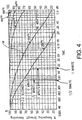
- Fig. 3 is a graph illustrating how fully thermally tempered plate glass loses original temper upon exposure to different temperatures for different periods of time, where the original center tension stress is 3,200 MU per inch.
- the x-axis in Fig. 3 is exponentially representative of time in hours (from 1 to 1,000 hours), while the y-axis is indicative of the percentage of original temper strength remaining after heat exposure.
- Fig. 4 is a graph similar to Fig. 3 , except that the x-axis in Fig. 4 extends from zero to one hour exponentially.
- Fig. 3 Seven different curves are illustrated in Fig. 3 , each indicative of a different temperature exposure in degrees Fahrenheit (°F).
- the different curves/lines are 400°F (across the top of the Fig. 3 graph), 500°F, 600°F, 700°F, 800°F, 900°F, and 950°F (the bottom curve of the Fig. 3 graph).
- a temperature of 900°F is equivalent to approximately 482°C, which is within the range utilized for forming the aforesaid conventional solder glass peripheral seal 4 in Figs. 1-2 .
- attention is drawn to the 900°F curve in Fig. 3 labeled by reference number 18.
- Only 20% of the original temper strength remains after one hour at this temperature (900°F or 482°C).
- Such a significant loss (i.e., 80% loss) of temper strength is of course undesirable.
- Another advantage associated with not heating up the entire unit for too long is that lower temperature pillar materials may then be used. This may or may not be desirable in some instances.
- the high temperatures applied to the entire VIG assembly may melt the glass or introduce stresses. These stresses may increase the likelihood of deformation of the glass and/or breakage.
- vacuum IG unit and corresponding method of making the same, where a structurally sound hermetic edge seal may be provided between opposing glass sheets.
- a vacuum IG unit including tempered glass sheets, wherein the peripheral seal is formed such that the glass sheets retain more of their original temper strength than with a conventional vacuum IG manufacturing technique where the entire unit is heated in order to form a solder glass edge seal.
- An aspect of this invention provides a method according to claim 1 of making a vacuum insulating glass (VIG) window unit.
- VOG vacuum insulating glass
- the method of making a vacuum insulating glass unit may include an edge seal thereof.
- Another aspect of this invention provides an apparatus according to claim 8 for forming edge seals for vacuum insulating glass units.
- seals do not mean that the seals are located at the absolute periphery or edge of the unit, but instead mean that the seal is at least partially located at or near (e.g., within about two inches) an edge of at least one substrate of the unit.
- edge as used herein is not limited to the absolute edge of a glass substrate but also may include an area at or near (e.g., within about two inches) of an absolute edge of the substrate(s).
- VIP assembly refers to an intermediate product prior to the VIG's edges being sealed and evacuation of the recess including, for example, two parallel-spaced apart substrates and a frit.
- the frit may be said to be “on” or “supported” by one or more of the substrates herein, this does not mean that the frit must directly contact the substrate(s).
- the word “on” covers both directly and indirectly on, so that the frit may be considered “on” a substrate even if other material (e,g., a coating and/or thin film) is provided between the substrate and the frit.
- a method of preferential heating for fruit edge seal of vacuum insulated glass units using a unitized zoned oven is provided.
- the pre-assembled unit is first heated to an intermediate temperature lower than that required to melt the frit seal (e.g., a temperature of about 200-300°C).
- the edge of the unit is further heated with localized heat from a substantially linear focused infrared (IR) heat source that is configured to generate IR radiation at a near infrared wavelength (e.g., a wavelength of about 0,7-5,0 ⁇ m) and, more preferably, of about 1.1-1.4 ⁇ m, in order to provide a localized temperature of from about 350-500°C until the frit is melted.
- IR focused infrared
- the techniques of this invention advantageously consume less energy and save time when the samples cool down.
- the localized temperature may be determined based in part on the material(s) comprising the frit. For example, lead-inclusive frits tend to require lower temperatures than silver-inclusive frits.
- the unitized oven of this invention includes multiple chambers. Generally, the chambers will correspond to an entrance zone, an edge sealing zone, and an exit zone.
- the unitized oven includes multiple chambers for accomplishing the functionality of a single zone (e.g., two entrance chambers are provided for performing entrance zone functionality, two exit chambers are provided for performing exit zone functionality, etc.)
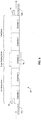
- FIG. 5 is a simplified side view illustrating an example layout of a five chamber oven 50 in accordance with an example embodiment.
- adjacent chambers may be separated by sealing doors (represented by dashed lines in between adjacent chambers) located between them.
- Linkage, pulleys, and/or other means may be provided to open and close such doors.
- the unitized oven 50 is semi-continuous in terms of product flow.
- a roller conveyer 52 or other transport technique maybe used to physically move a given VIG assembly from one zone and/or chamber to the next so that the VIG assembly and/or its contents are not disturbed or repositioned relative to one another.
- the roller conveyer 52 feeds VIG assemblies into the oven 50, e.g., through a first door 54, VIG assemblies may be moved into place and stopped when they reach a proper position within a chamber and/or zone,
- the position of the VIG assembly may be determined, for example, by photo-eye or other detection means, By way of example and without limitation, the position may be the center of a particular chamber, aligned within particular horizontal and vertical positions (e.g., as described in greater detail below in relation to Fig. 6 ), etc.
- it may be advantageous to temporarily stop a VIG assembly at a particular location for example, to allow the VIG assembly to heat sufficiently, to allow a solder frit to melt, etc.
- multiple VIG assemblies may be fed into the oven 50 at the same time so that they are processed in batch.
- up to five VIG assemblies may be processed by the oven at a time, with the process being started and stopped in dependence on the progress of each chamber.
- the edge sealing zone may require more time than the cooling performed in the exit zone chambers.
- the entrance zone e.g., chambers 1 and 2 in the Fig. 5 example embodiment
- substantially uniform heat may be applied to the VIG assembly so as to substantially uniformly heat the entire VIG assembly. Heating may be accomplished via IR radiation from an IR heat source or other means so as to reduce disturbance of the VIG assembly or its contents.
- substantially uniform heating sources are installed to maintain the VIG assembly as a whole at a predetermined background temperature. This may be accomplished by maintaining the entire VIG assembly at the intermediate temperature from the entrance zone and/or slightly increasing the temperature from the entrance zone.
- substantially linear focused IR heat sources 56 supply localized heating to the perimeter of the VIG assembly so as to melt the ceramic frit applied to the edges. IR heat is focused on peripheral edges, for example, by means of a parabolic mirror on an edge opposite to the VIG assembly. Further details of an example focusing mechanism are provided below with reference to Fig. 7 .
- this particular zone is termed an edge sealing zone, it will be appreciated that some edge sealing may occur in other zones. For example, most melting will occur within the edge sealing zone and some edge sealing will take place once the IR radiation sources are powered down, although the edges may continue to seal (e.g., the frit may begin or continue to harden) while in the exit zone.
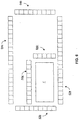
- Fig. 6 is an overhead view of the moving concentration of IR heat sources 62 and 64 in the edge sealing zone of a unitized oven in accordance with an example embodiment.
- the frit melting oven is designed such that variously sized VIG assemblies may be sealed
- one corner of the focused IR bank is fixed in position (e.g., the corner proximate to banks 62a-b).
- banks 62a-b are fixed in position. In such example arrangements, only two sides of the focused IR bank would need to be repositioned to ensure proper frit melting.
- the IR sources also may be segmented into sections so that a part or all of the sections can be turned on at any time to adjust the length of heating to that of the VIG assembly size.
- Parts of these IR source banks 64a-b may be moved into various positions around the perimeter of the VIG assembly by mechanical means, such as, for example, arms, rollers on a rail, and/or other linkages. In Fig. 6 , this is shown as banks 64a-b being segmented and bank segments 64a'-b' being moved from their initial positions (designated by the dotted lines in the banks 64a-b) to positions proximate to the VIG assembly 1' (designated by the solid lines) to be edge sealed. In the Fig.
- IR sources corresponding to banks G4a'-b' and parts of 62a-b would be turned on; the rest of the IR sources in banks 64a-b and the non-proximate IR sources in banks 62a-b need not be turned on (e.g., they would may remain off).
- the localized heat source comprises first, second, third, and fourth banks of infrared heat source elements, the banks being arranged such that the infrared heat source is substantially rectangularly shaped within the edge melting zone.
- the first and second banks are fixed in position and constitute two substantially perpendicular legs of the substantially rectangularly shaped infrared heat source, and the third and fourth banks constitute the other two substantially perpendicular legs of the substantially rectangularly shaped infrared heat source.
- the infrared heat source elements of the second and third banks are movable in dependence on a size of the unit so as to move closer to the edges to be sealed
- the angle of the focusing mirror may be adjustable in certain example embodiments to allow the heat to be focused more precisely on the VIG assembly perimeters (as described in greater detail below with reference to Fig. 7 ).
- the IR segmented source movement and/or focusing may be computer-controlled to adjust the results of the individual units.
- the VIG assembly 1' to be edge sealed may be elevated such that it is more proximate to the IR sources. This may be accomplished by moving it into a proper X-Y position with respect to the IR banks 62a-b, moving portions of the movable IR banks 64a-b, and lifting the VIG assembly 1' into position.
- the IR sources within the banks may be IR tubes.
- the IR tubes may be close enough to each to provide heating across the edges of the VIG assembly (e.g., without leaving "gaps," or unheated or substantially differently heated areas around the edges), but also maybe far enough away from each other to allow for movement of such tubes.
- the IR tubes may be located approximately 5 mm apart in certain example embodiments.
- the sizes of the banks may vary in dependence on the needs of the VIG unit manufacturing process. Also by way of example and without limitation, banks of about 2-3 meters should accommodate most standard VIG unit manufacturing requirements.
- the VIG assembly is cooled down in an exit zone comprising two chambers, e.g., in a stepwise manner via chambers 4 and 5 of Fig. 5 .
- Each successive exit zone chamber is maintained at a lower temperature than the previous exit zone chamber.
- This arrangement may be enabled by using forced convective air cooling, cooling water piping, and/or other cooling means suitable for removing heat from the particular exit zone chamber.
- the VIG assembly may be rolled out of the oven 50 through exit door 58 via rollers 52b.
- Fig. 7 is a side view of a concentration and/or focusing mirror 72 located proximate to an IR heating element 74 in accordance with an example embodiment. It will be appreciated that any type of concentrating and/or focusing mechanism may be used in connection with certain other example embodiments.
- IR radiation from IR heating element 74 is focused and/or concentrated by the parabolic mirror 72 onto or proximate to solder frit 4.
- the mirror 72 may be moved and/or repositioned to cause more or less of the peripheral edges of the VIG assembly 1' to be heated, to focus IR radiation to or away from the substrates 2 and 3, etc.
- a pre-assembled VIG assembly which may include a pre-applied and fired perimeter frit ink, enters the oven.
- the VIG assembly In the entrance zone, the VIG assembly is heated up to a predetermined temperature of between about 200-300°C. This may be accomplished using staged heating in two entrance chambers, so that the entire VIG assembly is pre-heated to two intermediate temperatures.
- the VIG assembly will enter into the oven at room temperature (e.g., which typically is about 23°C, although it will be appreciated that other processing environments and/or conditions may implement a different "room temperature").
- the entire VIG assembly may be heated to about 75°C in a first entrance zone chamber and then to about 150°C in a second entrance zone chamber.
- the entire VIG assembly is heated to about 200°C, and an IR heat source (e.g., a computer-controlled substantially linear IR heat source) is moved into position and focused around the perimeter of the VIG assembly,
- the IR heat source is activated at a predetermined distance (e.g., from about 0.5-10 cm) from the edge of the VIG assembly, depending in part on the focusing/concentrating mirror, whether the IR radiation is meant to "contact" the top and/or bottom substrates or just the sides proximate to the frit, etc,
- the IR heat source is focused, e.g., by means of a parabolic mirror provided on a side of the IR heat source opposite to the VIG assembly.
- the temperature of the frit on the perimeter of the VIG assembly is controlled to about 350-500°C, which is suitable to melt the frit but still below the melting point of the glass substrates, which varies from about 600-800°C based on the composition of the glass.
- the glass temperature remains at the background temperature, Accordingly, heat strengthened or tempered glass, if utilized, is not detempered or suffers a reduced amount of de-tempering during the frit heating and/or melting processes.
- the VIG assembly is transported to the exit zone.
- the exit zone includes two temperature ramp-down areas (or chambers). The temperature is reduced so that the VIG assembly is at a temperature less than about 100°C when it exits the oven, In a first exit chamber, the temperature of the entire VIG assembly will be reduced to about 150°C and then to about 100°C in a second exit chamber.
- Fig. 8 is an illustrative flowchart showing a process for providing localized heating to frit edge seals of a VIG assembly via a unitized oven.
- a VIG assembly including a plurality of edges to be sealed is inserted into a unitized oven.
- a roller conveyer may convey the VIG assembly into the oven, e.g., through a door.
- the VIG assembly is pro-heated to two intermediate temperatures in an entrance zone of the unitized oven. The intermediate temperatures are below the melting points of glass and the frit along the edge to be sealed.
- Localized heat is provided to the edges of the VIG assembly to be sealed (e.g., using one or more substantially linear IR heat sources, producing IR radiation having a near infrared wavelength (e.g., a wavelength of about 0.7-5.0 ⁇ m) and, more preferably, of about 1.1-1.4 ⁇ m) in an edge sealing zone of the unitized oven in step S86,
- the localized heat is at a temperature above the intermediate temperatures and is sufficient to cause the frit around the edges to melt, The temperatures may be chosen in dependence on the composition of the frit material.
- the VIG assembly, apart from the areas proximate to the peripheral edges to be sealed, are kept at a temperature close to that of the intermediate temperature (e.g., at a temperature sufficiently low so as to avoid melting of the glass).
- a plurality of heat sources are provided, e.g., within a bank. At least some of the banks may be fixed in position.
- the VIG assembly may be positioned proximate to the fixed banks so that at least some of the edges to be sealed are adjacent to the fixed banks.
- Additional banks including movable heat sources may be positioned so as to provide heat proximate to the edges of the VIG assembly that are not adjacent to the fixed banks.
- the areas to be heated may be more finely tuned by providing a concentration and/or focusing mirror.
- step S88 the VIG assembly is cooled in an exit zone of the oven.
- the pre-heating and cooling of the VIG assembly are staged so as to reduce the chances of breakage of the VIG assembly and/or de-tempering of the substrates comprising the VIG assembly.
- Multiple chambers are provided for the ramping-up of temperatures and the cooling processes, e.g., when the heating and cooling processes are staged.
- certain example embodiments advantageously heat, melt, and cool the frit quickly. This helps produce a temperature gradient proximate to the edges of the VIG assembly. The temperature gradient, in turn, helps reduce de-tempering and/or the chances of breakage of the glass. In certain example embodiments, at least certain portions of a thermally tempered glass sheet(s)/substrate(s) of the VIG unit lose no more than about 50% of original temper strength.
- the substrates may be glass substrates, heat strengthened substrates, tempered substrates, etc.
Description
- This invention relates to edge sealing techniques for vacuum insulating glass (VIG) units. More particularly, this invention relates to techniques for providing localized heating to edge seals of units, and unitized ovens for accomplishing the same.
- Vacuum IG units are known in the art. For example, see
U.S. Patent Nos. 5,664,395 ,5,657,607 , and5,902,652 . - The
EP 1571134 A1 discloses a process for producing vacuum glass panels and a vacuum glass panel produced thereby. In the herein described process, tempered sheet glass members are preheated to a given temperature and thereafter edge portions of the thermally tempered glass sheet members are locally heated in order to melt a glass paste. - The
JP 2002 137939 A - The
EP 0 061 183 A - The
EP 1 216 971 A1 -
Figs. 1-2 illustrate a conventional vacuum IG unit (vacuum IG unit or VIG unit).Vacuum IG unit 1 includes two spacedapart glass substrates low pressure space 6 therebetween. Glass sheets/substrates solder glass 4 and an array of support pillars orspacers 5. - Pump out
tube 8 is hermetically sealed bysolder glass 9 to an aperture orhole 10 which passes from an interior surface ofglass sheet 2 to the bottom ofrecess 11 in the exterior face ofsheet 2. A vacuum is attached to pump outtube 8 so that the interior cavity betweensubstrates space 6. After evacuation,tube 8 is melted to seal the vacuum. Recess 11 retains sealedtube 8. Optionally, achemical getter 12 may be included withinrecess 13. - Conventional vacuum IG units, with their fused solder glass
peripheral seals 4, have been manufactured as follows. Glass frit in a solution (ultimately to form solder glass edge seal 4) is initially deposited around the periphery ofsubstrate 2. Theother substrate 3 is brought down over top ofsubstrate 2 so as tosandwich spacers 5 and the glass frit/solution therebetween. The entireassembly including sheets glass sheets edge seal 4. This approximately 500°C temperature is maintained for from about one to eight hours. After formation of the peripheral/edge seal 4 and the seal aroundtube 8, the assembly is cooled to room temperature. It is noted thatcolumn 2 ofU.S. Patent No. 5,664,395 states that a conventional vacuum IG processing temperature is approximately 500°C for one hour. Inventor Collins of the '395 patent states in "Thermal Outgassing of Vacuum Glazing," by Lenzen, Turner and Collins, that "the edge seal process is currently quite slow: typically the temperature of the sample is increased at 200°C per hour, and held for one hour at a constant value ranging from 430°C and 530°C depending on the solder glass composition." After formation ofedge seal 4, a vacuum is drawn via the tube to formlow pressure space 6. - Unfortunately, the aforesaid high temperatures and long heating times of the entire assembly utilized in the formulation of
edge seal 4 are undesirable, especially when it is desired to use a heat strengthened or tempered glass substrate(s) 2, 3 in the vacuum IG unit. As shown inFigs. 3-4 , tempered glass loses temper strength upon exposure to high temperatures as a function of heating time. Moreover, such high processing temperatures may adversely affect certain low-E coating(s) that may be applied to one or both of the glass substrates in certain instances. -
Fig. 3 is a graph illustrating how fully thermally tempered plate glass loses original temper upon exposure to different temperatures for different periods of time, where the original center tension stress is 3,200 MU per inch. The x-axis inFig. 3 is exponentially representative of time in hours (from 1 to 1,000 hours), while the y-axis is indicative of the percentage of original temper strength remaining after heat exposure.Fig. 4 is a graph similar toFig. 3 , except that the x-axis inFig. 4 extends from zero to one hour exponentially. - Seven different curves are illustrated in
Fig. 3 , each indicative of a different temperature exposure in degrees Fahrenheit (°F). The different curves/lines are 400°F (across the top of theFig. 3 graph), 500°F, 600°F, 700°F, 800°F, 900°F, and 950°F (the bottom curve of theFig. 3 graph). A temperature of 900°F is equivalent to approximately 482°C, which is within the range utilized for forming the aforesaid conventional solder glassperipheral seal 4 inFigs. 1-2 . Thus, attention is drawn to the 900°F curve inFig. 3 , labeled byreference number 18. As shown, only 20% of the original temper strength remains after one hour at this temperature (900°F or 482°C). Such a significant loss (i.e., 80% loss) of temper strength is of course undesirable. - In
Figs. 3-4 , it is noted that much better temper strength remains in a thermally tempered sheet when it is heated to a temperature of 800°F (about 428°C) for one hour as opposed to 900°F for one hour. Such a glass sheet retains about 70% of its original temper strength after one hour at 800°F, which is significantly better than the less than 20% when at 900°F for the same period of time. - Another advantage associated with not heating up the entire unit for too long is that lower temperature pillar materials may then be used. This may or may not be desirable in some instances.
- Even when non-tempered glass substrates are used, the high temperatures applied to the entire VIG assembly may melt the glass or introduce stresses. These stresses may increase the likelihood of deformation of the glass and/or breakage.
- Thus, it will be appreciated that there is a need in the art for vacuum IG unit, and corresponding method of making the same, where a structurally sound hermetic edge seal may be provided between opposing glass sheets. There also exists a need in the art for a vacuum IG unit including tempered glass sheets, wherein the peripheral seal is formed such that the glass sheets retain more of their original temper strength than with a conventional vacuum IG manufacturing technique where the entire unit is heated in order to form a solder glass edge seal.
- An aspect of this invention provides a method according to
claim 1 of making a vacuum insulating glass (VIG) window unit. - The method of making a vacuum insulating glass unit may include an edge seal thereof.
- Another aspect of this invention provides an apparatus according to
claim 8 for forming edge seals for vacuum insulating glass units. - These and other features and advantages may be better and more completely understood by reference to the following detailed description of exemplary illustrative embodiments in conjunction with the drawings, of which:
-
FIGURE 1 is a prior art cross-sectional view of a conventional vacuum IG unit; -
FIGURE 2 is a prior art top plan view of the bottom substrate, edge seal, and spacers of theFig. 1 vacuum IG unit taken along the section line illustrated inFig. 1 ; -
FIGURE 3 is a graph correlating time (hours) versus percent tempering strength remaining, illustrating the loss of original temper strength for a thermally tempered sheet of glass after exposure to different temperatures for different periods of time; -
FIGURE 4 is a graph correlating time versus percent tempering strength remaining similar to that ofFig. 3 , except that a smaller time period is provided on the x-axis; -
FIGURE 5 is a simplified side view illustrating an example layout of a five chamber oven in accordance with an example embodiment; -
FIGURE 6 is an overhead view of the moving concentration of IR heat sources in the edge sealing zone of a unitized oven in accordance with an example embodiment; -
FIGURE 7 is a side view of a concentration and/or focusing mirror located proximate to an IR heating element in accordance with an example embodiment; and -
FIGURE 8 is an illustrative flowchart showing a process for providing localized heating to frit edge seals of a VIG assembly via a unitized oven, in accordance with an example embodiment. - "Peripheral" and "edge" seals herein do not mean that the seals are located at the absolute periphery or edge of the unit, but instead mean that the seal is at least partially located at or near (e.g., within about two inches) an edge of at least one substrate of the unit. Likewise, "edge" as used herein is not limited to the absolute edge of a glass substrate but also may include an area at or near (e.g., within about two inches) of an absolute edge of the substrate(s). Also, it will be appreciated that as used herein the term "VIG assembly" refers to an intermediate product prior to the VIG's edges being sealed and evacuation of the recess including, for example, two parallel-spaced apart substrates and a frit. Also, while the frit may be said to be "on" or "supported" by one or more of the substrates herein, this does not mean that the frit must directly contact the substrate(s). In other words, the word "on" covers both directly and indirectly on, so that the frit may be considered "on" a substrate even if other material (e,g., a coating and/or thin film) is provided between the substrate and the frit.
- In this invention, a method of preferential heating for fruit edge seal of vacuum insulated glass units using a unitized zoned oven is provided. The pre-assembled unit is first heated to an intermediate temperature lower than that required to melt the frit seal (e.g., a temperature of about 200-300°C). Then, the edge of the unit is further heated with localized heat from a substantially linear focused infrared (IR) heat source that is configured to generate IR radiation at a near infrared wavelength (e.g., a wavelength of about 0,7-5,0 µm) and, more preferably, of about 1.1-1.4 µm, in order to provide a localized temperature of from about 350-500°C until the frit is melted. At the same time, if tempered or heat strengthened glass is used, at least certain portions of a thermally tempered glass sheet(s)/substrate(s) of the VIG unit lose no more than about 50% of original temper strength, as the majority of the area is still under the intermediate temperature. Because of the overall lower temperature, the techniques of this invention advantageously consume less energy and save time when the samples cool down. It will be appreciated that the localized temperature may be determined based in part on the material(s) comprising the frit. For example, lead-inclusive frits tend to require lower temperatures than silver-inclusive frits.
- The unitized oven of this invention includes multiple chambers. Generally, the chambers will correspond to an entrance zone, an edge sealing zone, and an exit zone. The unitized oven includes multiple chambers for accomplishing the functionality of a single zone (e.g., two entrance chambers are provided for performing entrance zone functionality, two exit chambers are provided for performing exit zone functionality, etc.)
- By way of example and without limitation,
Fig. 5 is a simplified side view illustrating an example layout of a fivechamber oven 50 in accordance with an example embodiment. In certain non-limiting implementations, adjacent chambers may be separated by sealing doors (represented by dashed lines in between adjacent chambers) located between them. Linkage, pulleys, and/or other means may be provided to open and close such doors. - The unitized
oven 50 is semi-continuous in terms of product flow. A roller conveyer 52 or other transport technique maybe used to physically move a given VIG assembly from one zone and/or chamber to the next so that the VIG assembly and/or its contents are not disturbed or repositioned relative to one another. At astart point 52a, the roller conveyer 52 feeds VIG assemblies into theoven 50, e.g., through afirst door 54, VIG assemblies may be moved into place and stopped when they reach a proper position within a chamber and/or zone, The position of the VIG assembly may be determined, for example, by photo-eye or other detection means, By way of example and without limitation, the position may be the center of a particular chamber, aligned within particular horizontal and vertical positions (e.g., as described in greater detail below in relation toFig. 6 ), etc. In certain example embodiments, it may be advantageous to temporarily stop a VIG assembly at a particular location, for example, to allow the VIG assembly to heat sufficiently, to allow a solder frit to melt, etc. - In certain example embodiments, multiple VIG assemblies may be fed into the
oven 50 at the same time so that they are processed in batch. For example, in a five chamber oven like the one shown inFig. 5 , up to five VIG assemblies may be processed by the oven at a time, with the process being started and stopped in dependence on the progress of each chamber. For example, the edge sealing zone may require more time than the cooling performed in the exit zone chambers. Thus, there may be some delay built into the process to account for the different process times of the different zones and/or chambers. - The entrance zone (e.g.,
chambers Fig. 5 example embodiment) is equipped with substantially uniform heat sources so that the VIG assembly is heatable in stages. That is, substantially uniform heat may be applied to the VIG assembly so as to substantially uniformly heat the entire VIG assembly. Heating may be accomplished via IR radiation from an IR heat source or other means so as to reduce disturbance of the VIG assembly or its contents. - In an edge sealing zone (e.g.,
chamber 3 ofFig. 5 ), substantially uniform heating sources are installed to maintain the VIG assembly as a whole at a predetermined background temperature. This may be accomplished by maintaining the entire VIG assembly at the intermediate temperature from the entrance zone and/or slightly increasing the temperature from the entrance zone. In the meantime, substantially linear focusedIR heat sources 56 supply localized heating to the perimeter of the VIG assembly so as to melt the ceramic frit applied to the edges. IR heat is focused on peripheral edges, for example, by means of a parabolic mirror on an edge opposite to the VIG assembly. Further details of an example focusing mechanism are provided below with reference toFig. 7 . Although this particular zone is termed an edge sealing zone, it will be appreciated that some edge sealing may occur in other zones. For example, most melting will occur within the edge sealing zone and some edge sealing will take place once the IR radiation sources are powered down, although the edges may continue to seal (e.g., the frit may begin or continue to harden) while in the exit zone. -
Fig. 6 is an overhead view of the moving concentration of IR heat sources 62 and 64 in the edge sealing zone of a unitized oven in accordance with an example embodiment. As shown inFig. 6 , the frit melting oven is designed such that variously sized VIG assemblies may be sealed In certain example embodiments, one corner of the focused IR bank is fixed in position (e.g., the corner proximate tobanks 62a-b). In theFig. 6 example,banks 62a-b are fixed in position. In such example arrangements, only two sides of the focused IR bank would need to be repositioned to ensure proper frit melting. The IR sources also may be segmented into sections so that a part or all of the sections can be turned on at any time to adjust the length of heating to that of the VIG assembly size. Parts of theseIR source banks 64a-b may be moved into various positions around the perimeter of the VIG assembly by mechanical means, such as, for example, arms, rollers on a rail, and/or other linkages. InFig. 6 , this is shown asbanks 64a-b being segmented andbank segments 64a'-b' being moved from their initial positions (designated by the dotted lines in thebanks 64a-b) to positions proximate to the VIG assembly 1' (designated by the solid lines) to be edge sealed. In theFig. 6 embodiment, only IR sources corresponding to banks G4a'-b' and parts of 62a-b would be turned on; the rest of the IR sources inbanks 64a-b and the non-proximate IR sources inbanks 62a-b need not be turned on (e.g., they would may remain off). - Thus, as is shown in
Fig. 6 , the localized heat source comprises first, second, third, and fourth banks of infrared heat source elements, the banks being arranged such that the infrared heat source is substantially rectangularly shaped within the edge melting zone. The first and second banks are fixed in position and constitute two substantially perpendicular legs of the substantially rectangularly shaped infrared heat source, and the third and fourth banks constitute the other two substantially perpendicular legs of the substantially rectangularly shaped infrared heat source. The infrared heat source elements of the second and third banks are movable in dependence on a size of the unit so as to move closer to the edges to be sealed - In addition, the angle of the focusing mirror may be adjustable in certain example embodiments to allow the heat to be focused more precisely on the VIG assembly perimeters (as described in greater detail below with reference to
Fig. 7 ). In certain example embodiments, the IR segmented source movement and/or focusing may be computer-controlled to adjust the results of the individual units. Still further, the VIG assembly 1' to be edge sealed may be elevated such that it is more proximate to the IR sources. This may be accomplished by moving it into a proper X-Y position with respect to theIR banks 62a-b, moving portions of themovable IR banks 64a-b, and lifting the VIG assembly 1' into position. - By way of example and without limitation, the IR sources within the banks may be IR tubes. The IR tubes may be close enough to each to provide heating across the edges of the VIG assembly (e.g., without leaving "gaps," or unheated or substantially differently heated areas around the edges), but also maybe far enough away from each other to allow for movement of such tubes. Thus, by way of example and without limitation, the IR tubes may be located approximately 5 mm apart in certain example embodiments. The sizes of the banks may vary in dependence on the needs of the VIG unit manufacturing process. Also by way of example and without limitation, banks of about 2-3 meters should accommodate most standard VIG unit manufacturing requirements.
- Referring once again to
Fig. 5 , the VIG assembly is cooled down in an exit zone comprising two chambers, e.g., in a stepwise manner viachambers Fig. 5 . Each successive exit zone chamber is maintained at a lower temperature than the previous exit zone chamber. This arrangement may be enabled by using forced convective air cooling, cooling water piping, and/or other cooling means suitable for removing heat from the particular exit zone chamber. Ultimately, the VIG assembly may be rolled out of theoven 50 throughexit door 58 viarollers 52b. -
Fig. 7 is a side view of a concentration and/or focusingmirror 72 located proximate to anIR heating element 74 in accordance with an example embodiment. It will be appreciated that any type of concentrating and/or focusing mechanism may be used in connection with certain other example embodiments. IR radiation fromIR heating element 74 is focused and/or concentrated by theparabolic mirror 72 onto or proximate tosolder frit 4. Themirror 72 may be moved and/or repositioned to cause more or less of the peripheral edges of the VIG assembly 1' to be heated, to focus IR radiation to or away from thesubstrates - A more detailed description of the VIG assembly edge sealing process will now be provided. A pre-assembled VIG assembly, which may include a pre-applied and fired perimeter frit ink, enters the oven. In the entrance zone, the VIG assembly is heated up to a predetermined temperature of between about 200-300°C. This may be accomplished using staged heating in two entrance chambers, so that the entire VIG assembly is pre-heated to two intermediate temperatures. In general, the VIG assembly will enter into the oven at room temperature (e.g., which typically is about 23°C, although it will be appreciated that other processing environments and/or conditions may implement a different "room temperature"). The entire VIG assembly may be heated to about 75°C in a first entrance zone chamber and then to about 150°C in a second entrance zone chamber.
- In the edge sealing zone, the entire VIG assembly is heated to about 200°C, and an IR heat source (e.g., a computer-controlled substantially linear IR heat source) is moved into position and focused around the perimeter of the VIG assembly, The IR heat source is activated at a predetermined distance (e.g., from about 0.5-10 cm) from the edge of the VIG assembly, depending in part on the focusing/concentrating mirror, whether the IR radiation is meant to "contact" the top and/or bottom substrates or just the sides proximate to the frit, etc, As noted above, the IR heat source is focused, e.g., by means of a parabolic mirror provided on a side of the IR heat source opposite to the VIG assembly. The temperature of the frit on the perimeter of the VIG assembly is controlled to about 350-500°C, which is suitable to melt the frit but still below the melting point of the glass substrates, which varies from about 600-800°C based on the composition of the glass. During the localized heating process in the edge sealing zone, the glass temperature remains at the background temperature, Accordingly, heat strengthened or tempered glass, if utilized, is not detempered or suffers a reduced amount of de-tempering during the frit heating and/or melting processes.
- Following the frit melting in the edge sealing zone, the VIG assembly is transported to the exit zone. The exit zone includes two temperature ramp-down areas (or chambers). The temperature is reduced so that the VIG assembly is at a temperature less than about 100°C when it exits the oven, In a first exit chamber, the temperature of the entire VIG assembly will be reduced to about 150°C and then to about 100°C in a second exit chamber.
-
Fig. 8 is an illustrative flowchart showing a process for providing localized heating to frit edge seals of a VIG assembly via a unitized oven. In step S82, a VIG assembly including a plurality of edges to be sealed is inserted into a unitized oven. A roller conveyer may convey the VIG assembly into the oven, e.g., through a door. In step S84, the VIG assembly is pro-heated to two intermediate temperatures in an entrance zone of the unitized oven. The intermediate temperatures are below the melting points of glass and the frit along the edge to be sealed. - Localized heat is provided to the edges of the VIG assembly to be sealed (e.g., using one or more substantially linear IR heat sources, producing IR radiation having a near infrared wavelength (e.g., a wavelength of about 0.7-5.0 µm) and, more preferably, of about 1.1-1.4 µm) in an edge sealing zone of the unitized oven in step S86, The localized heat is at a temperature above the intermediate temperatures and is sufficient to cause the frit around the edges to melt, The temperatures may be chosen in dependence on the composition of the frit material. The VIG assembly, apart from the areas proximate to the peripheral edges to be sealed, are kept at a temperature close to that of the intermediate temperature (e.g., at a temperature sufficiently low so as to avoid melting of the glass).
- In a step not shown, to provide localized heating, a plurality of heat sources (e,g., substantially linear IR heat sources) are provided, e.g., within a bank. At least some of the banks may be fixed in position. The VIG assembly may be positioned proximate to the fixed banks so that at least some of the edges to be sealed are adjacent to the fixed banks. Additional banks including movable heat sources may be positioned so as to provide heat proximate to the edges of the VIG assembly that are not adjacent to the fixed banks. The areas to be heated may be more finely tuned by providing a concentration and/or focusing mirror.
- Referring once again to
Fig. 8 , in step S88, the VIG assembly is cooled in an exit zone of the oven. The pre-heating and cooling of the VIG assembly are staged so as to reduce the chances of breakage of the VIG assembly and/or de-tempering of the substrates comprising the VIG assembly. Multiple chambers are provided for the ramping-up of temperatures and the cooling processes, e.g., when the heating and cooling processes are staged. - Thus, certain example embodiments advantageously heat, melt, and cool the frit quickly. This helps produce a temperature gradient proximate to the edges of the VIG assembly. The temperature gradient, in turn, helps reduce de-tempering and/or the chances of breakage of the glass. In certain example embodiments, at least certain portions of a thermally tempered glass sheet(s)/substrate(s) of the VIG unit lose no more than about 50% of original temper strength.
- It will be appreciated that the example embodiments described herein may be used in connection with a variety of different VIG assembly and/or other units or components. For example, the substrates may be glass substrates, heat strengthened substrates, tempered substrates, etc.
- While the invention has been described in connection with what is presently considered to be the most practical and preferred embodiment, it is to be understood that the invention is not to be limited to the disclosed embodiment, but on the contrary, is intended to cover various modifications and equivalent arrangements included within the scope of the appended claims.
Claims (10)
- A method of making a vacuum insulating glass window unit (1), the method comprising:providing first and second substantially parallel spaced-apart glass substrates (2, 3) and a frit (4) provided at least partially between the first and second glass substrates (2, 3) for sealing an edge of the vacuum insulating glass window unit (1);pre-heating the glass substrates (2, 3) and the frit (4) to at least one temperature below a melting point of the first and second substrates (2, 3) and below a melting point of the frit (4);providing localized near infrared inclusive heat proximate to the edge to be sealed so as to at least partially melt the frit (4), wherein a concentrating-mechanism concentrates and/or a focusing-mechanism focusses infrared radiation from an infrared heat source (62, 64, 74) to the solder frit (4); andcooling the unit (1) and allowing the frit (4) to harden in making the vacuum insulating glass window unit (1), wherein the method further comprises during the cooling, providing first and second reduced temperatures in this order, the first reduced temperature being 150°C and being provided in a first exit zone chamber whereas the second reduced temperature being less than 100°C and being provided in a second exit zone chamber.
- The method of claim 1 of making a vacuum insulating glass window unit (1), including an edge seal thereof, wherein the localized near infrared radiation is provided at a wavelength of 1.1-1.4 µm to the unit proximate to the edge portions to be sealed so as to provide a localized temperature from 350°-500°C, wherein the localized near infrared heat being provided to the unit (1) such that at least some areas of the unit (1) not proximate to the edge portions to be sealed are kept at a temperature(s) below frit-melting temperature.
- The method of claim 2, further comprising:initially providing the unit (1) at room temperature; andduring the pre-heating, providing first and second intermediate temperatures in this order, the first intermediate temperature being 75°C and the second intermediate temperature being 150°C.
- The method of claim 2, wherein the frit melting temperature is from 350-500°C.
- The method of claim 2, wherein the localized heat source is a substantially linear infrared heat source (62, 64, 74) configured to generate near infrared radiation.
- The method of claim 2 or 5, further comprising concentrating and/or focusing the near infrared radiation on or proximate to the frit via at least one parabolic mirror (72).
- The method of claim 5, further comprising providing the near infrared radiation at a wavelength(s) of 1.1-1.4 µm.
- An apparatus (50) for forming edge seals for vacuum insulating glass units (1), comprising:a pre-heating zone for receiving a unit (1) comprising first and second substantially parallel spaced-apart glass substrates (2, 3), one or more edge portions between the first and second substrates to be sealed, and a frit (4) for sealing a periphery of the substrates (2, 3), and the pre-heating zone being for pre-heating the unit (1) in its entirety to at least one intermediate temperature, each said intermediate temperature being below a melting point of the first and second substrates (2, 3) and below a melting point of the frit (4);an edge sealing zone including a localized heat source for providing localized heat to the unit (1) proximate to the edge portions to be sealed at a frit melting temperature, wherein a concentrating-mechanism concentrates and/or a focusing-mechanism focusses infrared radiation from an infrared heat source (62, 64, 74) to the solder frit (4), so that the frit melting temperature being sufficiently high enough to melt the frit, the localized heat being provided to the unit (1) such that areas of the unit (1) not proximate to the edge portions to be sealed are maintained at a temperature close to an intermediate temperature; anda cooling zone of the oven (50) for cooling the unit (1) in its entirety to at least one reduced temperature and allowing the frit (4) to harden, wherein during the cooling, providing first and second reduced temperatures in this order, the first reduced temperature being 150°C and the second reduced temperature being less than 100°C,wherein the cooling zone is an exit zone, and the apparatus further comprising first and second exit zone chambers of the exit zone to respectively provide the first and second reduced temperatures in this order.
- The apparatus (1) of claim 8, wherein the pre-heating zone is an entrance zone, and the apparatus further comprising first and second entrance zone chambers of the entrance zone to respectively provide first and second intermediate temperatures in this order, the first intermediate temperature being from 65- 85°C and the second intermediate temperature being from 140-160°C.
- The apparatus of claim 8, wherein the localized heat source is a substantially linear infrared heat source (62, 64, 74) configured to generate near infrared radiation and wherein preferably the localized heat source comprises first, second, third, and fourth banks of infrared heat source elements, the banks being arranged such that the infrared heat source is substantially rectangularly shaped within the edge melting zone,
wherein the first and second banks are fixed in position and constitute two substantially perpendicular legs of the substantially rectangularly shaped infrared heat source,
wherein the third and fourth banks constitute the other two substantially perpendicular legs of the substantially rectangularly shaped infrared heat source, and
wherein the infrared heat source elements of the second and third banks are movable in dependence on a size of the unit so as to move closer to the edges to be sealed.
Priority Applications (1)
| Application Number | Priority Date | Filing Date | Title |
|---|---|---|---|
| PL10187446T PL2292887T3 (en) | 2007-12-14 | 2008-12-02 | Localized heating of edge seals for a vacuum insulating glass unit, and/or unitized oven for accomplishing the same |
Applications Claiming Priority (2)
| Application Number | Priority Date | Filing Date | Title |
|---|---|---|---|
| US12/000,663 US8500933B2 (en) | 2007-12-14 | 2007-12-14 | Localized heating of edge seals for a vacuum insulating glass unit, and/or unitized oven for accomplishing the same |
| EP08862066.1A EP2231984B1 (en) | 2007-12-14 | 2008-12-02 | Localized heating of edge seals for a vacuum insulating glass unit, and/or unitized oven for accomplishing the same |
Related Parent Applications (3)
| Application Number | Title | Priority Date | Filing Date |
|---|---|---|---|
| EP08862066.1 Division | 2008-12-02 | ||
| EP08862066.1A Division-Into EP2231984B1 (en) | 2007-12-14 | 2008-12-02 | Localized heating of edge seals for a vacuum insulating glass unit, and/or unitized oven for accomplishing the same |
| EP08862066.1A Division EP2231984B1 (en) | 2007-12-14 | 2008-12-02 | Localized heating of edge seals for a vacuum insulating glass unit, and/or unitized oven for accomplishing the same |
Publications (3)
| Publication Number | Publication Date |
|---|---|
| EP2292887A2 EP2292887A2 (en) | 2011-03-09 |
| EP2292887A3 EP2292887A3 (en) | 2011-05-18 |
| EP2292887B1 true EP2292887B1 (en) | 2018-02-21 |
Family
ID=40404515
Family Applications (3)
| Application Number | Title | Priority Date | Filing Date |
|---|---|---|---|
| EP10187446.9A Active EP2292887B1 (en) | 2007-12-14 | 2008-12-02 | Localized heating of edge seals for a vacuum insulating glass unit, and/or unitized oven for accomplishing the same |
| EP08862066.1A Active EP2231984B1 (en) | 2007-12-14 | 2008-12-02 | Localized heating of edge seals for a vacuum insulating glass unit, and/or unitized oven for accomplishing the same |
| EP19153153.2A Pending EP3492682A1 (en) | 2007-12-14 | 2008-12-02 | Localized heating of edge seals for a vacuum insulating glass unit and/or unitized oven for accomplishing the same |
Family Applications After (2)
| Application Number | Title | Priority Date | Filing Date |
|---|---|---|---|
| EP08862066.1A Active EP2231984B1 (en) | 2007-12-14 | 2008-12-02 | Localized heating of edge seals for a vacuum insulating glass unit, and/or unitized oven for accomplishing the same |
| EP19153153.2A Pending EP3492682A1 (en) | 2007-12-14 | 2008-12-02 | Localized heating of edge seals for a vacuum insulating glass unit and/or unitized oven for accomplishing the same |
Country Status (11)
| Country | Link |
|---|---|
| US (2) | US8500933B2 (en) |
| EP (3) | EP2292887B1 (en) |
| JP (1) | JP5342562B2 (en) |
| KR (3) | KR101573477B1 (en) |
| CN (1) | CN101896680B (en) |
| DK (2) | DK2231984T3 (en) |
| ES (2) | ES2718252T3 (en) |
| PL (2) | PL2231984T3 (en) |
| RU (1) | RU2470129C2 (en) |
| TR (2) | TR201806932T4 (en) |
| WO (1) | WO2009078912A1 (en) |
Families Citing this family (49)
| Publication number | Priority date | Publication date | Assignee | Title |
|---|---|---|---|---|
| US8500933B2 (en) | 2007-12-14 | 2013-08-06 | Guardian Industries Corp. | Localized heating of edge seals for a vacuum insulating glass unit, and/or unitized oven for accomplishing the same |
| KR101042724B1 (en) * | 2009-12-17 | 2011-06-20 | (주)알가 | Apparatus for edge sealing of vacuum glass panel and method for vacuum glass panel using the same |
| EP2552847A4 (en) * | 2010-03-27 | 2013-10-02 | Robert S Jones | Vacuum insulating glass unit with viscous edge seal |
| US9689195B2 (en) | 2010-03-27 | 2017-06-27 | Robert S. Jones | Vacuum insulating glass unit with viscous edge seal |
| US9732552B2 (en) | 2010-03-27 | 2017-08-15 | Robert S. Jones | Vacuum insulating glass unit with viscous edge seal |
| CN101867514A (en) * | 2010-05-10 | 2010-10-20 | 北京交通大学 | Method for implementing fusion of network middleware |
| US20110290295A1 (en) | 2010-05-28 | 2011-12-01 | Guardian Industries Corp. | Thermoelectric/solar cell hybrid coupled via vacuum insulated glazing unit, and method of making the same |
| US9293653B2 (en) | 2010-10-08 | 2016-03-22 | Guardian Industries Corp. | Light source with light scattering features, device including light source with light scattering features, and/or methods of making the same |
| US8573804B2 (en) | 2010-10-08 | 2013-11-05 | Guardian Industries Corp. | Light source, device including light source, and/or methods of making the same |
| US8492788B2 (en) | 2010-10-08 | 2013-07-23 | Guardian Industries Corp. | Insulating glass (IG) or vacuum insulating glass (VIG) unit including light source, and/or methods of making the same |
| US8357553B2 (en) | 2010-10-08 | 2013-01-22 | Guardian Industries Corp. | Light source with hybrid coating, device including light source with hybrid coating, and/or methods of making the same |
| US20120090246A1 (en) | 2010-10-15 | 2012-04-19 | Guardian Industries Corp. | Refrigerator/freezer door, and/or method of making the same |
| CN102476926B (en) * | 2010-11-23 | 2013-12-18 | 洛阳兰迪玻璃机器股份有限公司 | Vacuum glass sealing device |
| US8434904B2 (en) | 2010-12-06 | 2013-05-07 | Guardian Industries Corp. | Insulated glass units incorporating emitters, and/or methods of making the same |
| MY166708A (en) * | 2010-12-28 | 2018-07-18 | Tvp Solar Sa | Method for performing a frit firing cycle in the manufacturing of a vacuum solar thermal panel |
| US8667762B2 (en) | 2010-12-29 | 2014-03-11 | Guardian Industries Corp. | Grid keeper for insulating glass unit, and/or insulating glass unit incorporating the same |
| US9359247B2 (en) | 2011-02-22 | 2016-06-07 | Guardian Industries Corp. | Coefficient of thermal expansion filler for vanadium-based frit materials and/or methods of making and/or using the same |
| US9458052B2 (en) | 2011-02-22 | 2016-10-04 | Guardian Industries Corp. | Coefficient of thermal expansion filler for vanadium-based frit materials and/or methods of making and/or using the same |
| US9822580B2 (en) | 2011-02-22 | 2017-11-21 | Guardian Glass, LLC | Localized heating techniques incorporating tunable infrared element(s) for vacuum insulating glass units, and/or apparatuses for same |
| US9290408B2 (en) | 2011-02-22 | 2016-03-22 | Guardian Industries Corp. | Vanadium-based frit materials, and/or methods of making the same |
| US9309146B2 (en) | 2011-02-22 | 2016-04-12 | Guardian Industries Corp. | Vanadium-based frit materials, binders, and/or solvents and methods of making the same |
| US8802203B2 (en) | 2011-02-22 | 2014-08-12 | Guardian Industries Corp. | Vanadium-based frit materials, and/or methods of making the same |
| US8985095B2 (en) | 2011-05-17 | 2015-03-24 | Guardian Industries Corp. | Roof-mounted water heater |
| CA2844097A1 (en) * | 2011-08-02 | 2013-02-07 | Robert S. Jones | Vacuum insulating glass unit with viscous edge seal |
| KR101379061B1 (en) * | 2011-08-11 | 2014-03-28 | (주)엘지하우시스 | Heat strengthened vacuum glass |
| US10274203B2 (en) * | 2012-05-03 | 2019-04-30 | Electrolux Home Products Corporation N.V. | Arrangement of glass panels for a heat insulated oven door for a cooking oven |
| US9346708B2 (en) | 2012-05-04 | 2016-05-24 | Corning Incorporated | Strengthened glass substrates with glass frits and methods for making the same |
| HUE043865T2 (en) * | 2012-05-18 | 2019-09-30 | Panasonic Ip Man Co Ltd | Production method of multiple panes |
| JP5821011B2 (en) * | 2012-05-18 | 2015-11-24 | パナソニックIpマネジメント株式会社 | Method for producing double-glazed glass |
| US9428952B2 (en) * | 2012-05-31 | 2016-08-30 | Guardian Industries Corp. | Vacuum insulated glass (VIG) window unit with reduced seal height variation and method for making same |
| US8608525B1 (en) | 2012-06-05 | 2013-12-17 | Guardian Industries Corp. | Coated articles and/or devices with optical out-coupling layer stacks (OCLS), and/or methods of making the same |
| US11554986B2 (en) | 2013-02-26 | 2023-01-17 | Corning Incorporated | Decorative porous inorganic layer compatible with ion exchange processes |
| CN103588386B (en) * | 2013-11-11 | 2016-05-18 | 青岛亨达玻璃科技有限公司 | The production method of toughened vacuum glass |
| US9988302B2 (en) | 2014-02-04 | 2018-06-05 | Guardian Glass, LLC | Frits for use in vacuum insulating glass (VIG) units, and/or associated methods |
| US9593527B2 (en) | 2014-02-04 | 2017-03-14 | Guardian Industries Corp. | Vacuum insulating glass (VIG) unit with lead-free dual-frit edge seals and/or methods of making the same |
| US9498072B2 (en) | 2014-02-11 | 2016-11-22 | Anthony, Inc. | Display case door assembly with tempered glass vacuum panel |
| US10165870B2 (en) | 2014-02-11 | 2019-01-01 | Anthony, Inc. | Display case door assembly with vacuum panel |
| TWI680026B (en) * | 2014-04-21 | 2019-12-21 | 美商康寧公司 | Method for welding first and second substrates,and method for producing glass and/or glass-ceramic packaging |
| KR101578073B1 (en) * | 2014-07-14 | 2015-12-16 | 코닝정밀소재 주식회사 | Method for hermetic sealing and hermetically sealed substrate package |
| US10597933B2 (en) * | 2015-09-29 | 2020-03-24 | Panasonic Intellectual Property Management Co., Ltd. | Glass panel unit and windowpane |
| US10095088B2 (en) * | 2016-06-13 | 2018-10-09 | Olympus Corporation | Optical apparatus |
| US9687087B1 (en) | 2016-06-16 | 2017-06-27 | Anthony, Inc. | Display case door assembly with vacuum panel and lighting features |
| EP3363983B1 (en) * | 2017-02-17 | 2021-10-27 | VKR Holding A/S | Vacuum insulated glazing unit |
| EP3583080B1 (en) * | 2017-02-17 | 2024-01-03 | VKR Holding A/S | Top frit heat treatment |
| EP3647291A4 (en) * | 2017-06-30 | 2020-07-01 | Panasonic Intellectual Property Management Co., Ltd. | Production method for glass panel unit |
| EP3827152B1 (en) * | 2018-07-23 | 2022-12-14 | VKR Holding A/S | Preactive oxygen modification to form peripheral seal for vacuum insulated glazing (vig) unit |
| RU200153U1 (en) * | 2020-02-05 | 2020-10-08 | Общество с ограниченной ответственностью "ПТК ПРИБОРСЕРВИС" (ООО "ПТК ПРИБОРСЕРВИС") | DEVICE OF A VACUUM OVEN-LAMINATOR FOR THE PRODUCTION OF GLASS-PACKET-TRIPLEX |
| KR102200381B1 (en) | 2020-02-10 | 2021-01-08 | 주식회사 자이트게버 | bottom weights device for horizontal blinds |
| US11802436B2 (en) | 2020-12-30 | 2023-10-31 | Guardian Glass, LLC | Vacuum insulated glass (VIG) window unit with metal alloy spacers, and/or methods of making the same |
Family Cites Families (43)
| Publication number | Priority date | Publication date | Assignee | Title |
|---|---|---|---|---|
| US3632324A (en) * | 1967-08-10 | 1972-01-04 | Okaya Electric Industry Co | Method of sealing display cathodes in a glass envelope |
| FR2288069A1 (en) * | 1974-10-15 | 1976-05-14 | Saint Gobain | DEVICE FOR COATING THE FOUR AREAS OF A MULTIPLE GLAZING WITH A PLASTIC MASTIC |
| SU852811A1 (en) | 1979-12-18 | 1981-08-07 | Грузинский Ордена Ленина И Орденатрудового Красного Знамени Политехническийинститут Им. B.И.Ленина | Black enamel |
| DE3126996A1 (en) | 1981-03-21 | 1982-09-30 | Karl 7531 Neuhausen Lenhardt | METHOD FOR PRODUCING THE FIXED COMPOSITION OF INSULATING GLASS PANES |
| US4683154A (en) | 1985-08-19 | 1987-07-28 | The United States Of America As Represented By The United States Department Of Energy | Laser sealed vacuum insulation window |
| US4820365A (en) * | 1987-09-30 | 1989-04-11 | Dimension Industries, Inc. | Glass edge sealant curing system |
| SU1590472A1 (en) | 1987-11-16 | 1990-09-07 | Киевский Политехнический Институт Им.50-Летия Великой Октябрьской Социалистической Революции | Uneritted glaze |
| US5657607A (en) | 1989-08-23 | 1997-08-19 | University Of Sydney | Thermally insulating glass panel and method of construction |
| SU1694561A1 (en) | 1990-01-08 | 1991-11-30 | Государственный научно-исследовательский институт строительной керамики | Glaze |
| SU1791433A1 (en) | 1991-04-11 | 1993-01-30 | Gnii Stroitelnoj Keramiki | Glaze |
| SG44580A1 (en) | 1992-01-31 | 1997-12-19 | Univ Sydney | Improvements to thermally insulating glass panels |
| EP0953719B1 (en) | 1993-06-30 | 2003-10-15 | The University Of Sydney | Methods of construction of evacuated glazing |
| US5489321A (en) | 1994-07-14 | 1996-02-06 | Midwest Research Institute | Welding/sealing glass-enclosed space in a vacuum |
| DE19545422C2 (en) | 1995-12-06 | 1998-11-19 | Inst Physikalische Hochtech Ev | Process for anodic bonding of silicon components with glass components |
| RU2150564C1 (en) * | 1999-01-27 | 2000-06-10 | Ивлюшкин Алексей Николаевич | Glass block for windows |
| US6336984B1 (en) | 1999-09-24 | 2002-01-08 | Guardian Industries Corporation | Vacuum IG window unit with peripheral seal at least partially diffused at temper |
| US6365242B1 (en) | 1999-07-07 | 2002-04-02 | Guardian Industries Corp. | Peripheral seal for vacuum IG window unit |
| US6399169B1 (en) | 1999-07-07 | 2002-06-04 | Guardian Industries Corp. | Vacuum IG window unit with dual peripheral seal |
| AU5406399A (en) * | 1999-08-27 | 2001-03-26 | Qingdao Synergy Technology Appliance Co., Ltd. | The method for manufacturing vacuum glazing and its application mechanical system |
| US6946171B1 (en) | 1999-09-22 | 2005-09-20 | Guardian Industries Corp. | Vacuum IG pillar with lubricating and/or reflective coating |
| US6478911B1 (en) | 2000-09-27 | 2002-11-12 | Guardian Industries Corp. | Vacuum IG window unit with edge seal formed via microwave curing, and corresponding method of making the same |
| US6444281B1 (en) | 1999-10-13 | 2002-09-03 | Guardian Industries Corp. | Vacuum IG window unit with spacers between first and second edge seals |
| US6383580B1 (en) | 1999-11-12 | 2002-05-07 | Guardian Industries Corp. | Vacuum IG window unit with edge mounted pump-out tube |
| US6503583B2 (en) | 1999-11-16 | 2003-01-07 | Guardian Industries Corp. | Vacuum IG window unit with fiber inclusive edge seal |
| US6541083B1 (en) | 2000-01-11 | 2003-04-01 | Guardian Industries Corp. | Vacuum IG unit with alkali silicate edge seal and/or spacers |
| AU2001282271A1 (en) | 2000-08-11 | 2002-02-25 | Anthony John Cooper | Double glazing |
| US6701749B2 (en) | 2000-09-27 | 2004-03-09 | Guardian Industries Corp. | Vacuum IG window unit with edge seal at least partially diffused at temper and completed via microwave curing, and corresponding method of making the same |
| JP2002137939A (en) | 2000-10-30 | 2002-05-14 | Matsushita Electric Ind Co Ltd | Method of fabricating display panel and fabricating device therefor |
| JP2002179439A (en) * | 2000-12-12 | 2002-06-26 | Central Glass Co Ltd | Method for manufacturing low pressure double layered glass |
| JP4503196B2 (en) | 2001-03-07 | 2010-07-14 | 株式会社アルバック | Sealing chamber, panel holder and sealing method |
| CN1245780C (en) | 2001-04-10 | 2006-03-15 | 皇家菲利浦电子有限公司 | Combination quick release buckle and electrical connector |
| JP4203235B2 (en) | 2001-07-05 | 2008-12-24 | 日本板硝子株式会社 | Glass panel |
| US6692600B2 (en) | 2001-09-14 | 2004-02-17 | Guardian Industries Corp. | VIG evacuation with plasma excitation |
| US6926782B2 (en) | 2002-06-27 | 2005-08-09 | Glass Equipment Development, Inc. | Method and apparatus for processing sealant of an insulating glass unit |
| JP2004111084A (en) * | 2002-09-13 | 2004-04-08 | Canon Inc | Manufacturing method of vacuum flat panel display |
| JP2004182567A (en) | 2002-12-05 | 2004-07-02 | Nippon Sheet Glass Co Ltd | Method for manufacturing vacuum glass panel and vacuum glass panel manufactured by using the method |
| US20050217319A1 (en) | 2002-12-05 | 2005-10-06 | Nippon Sheet Glass Company, Limited | Vacuum glass panel manufacturing method and vacuum glass panel manufactured by the manufacturing method |
| US7344901B2 (en) | 2003-04-16 | 2008-03-18 | Corning Incorporated | Hermetically sealed package and method of fabricating of a hermetically sealed package |
| CN100497222C (en) * | 2004-04-01 | 2009-06-10 | 唐健正 | Reinforced vacuum glass manufacture method and vacuum glass made thereby |
| JP4393308B2 (en) | 2004-08-24 | 2010-01-06 | キヤノン株式会社 | Manufacturing method of image display device |
| EP2017236A4 (en) | 2006-05-02 | 2009-12-16 | Nippon Sheet Glass Co Ltd | Glass composition and glass spacer using the same |
| US8500933B2 (en) | 2007-12-14 | 2013-08-06 | Guardian Industries Corp. | Localized heating of edge seals for a vacuum insulating glass unit, and/or unitized oven for accomplishing the same |
| US8857698B2 (en) | 2009-11-18 | 2014-10-14 | Agc Glass Europe | Method for manufacturing insulating glazing |
-
2007
- 2007-12-14 US US12/000,663 patent/US8500933B2/en active Active
-
2008
- 2008-12-02 ES ES08862066T patent/ES2718252T3/en active Active
- 2008-12-02 EP EP10187446.9A patent/EP2292887B1/en active Active
- 2008-12-02 PL PL08862066T patent/PL2231984T3/en unknown
- 2008-12-02 PL PL10187446T patent/PL2292887T3/en unknown
- 2008-12-02 DK DK08862066.1T patent/DK2231984T3/en active
- 2008-12-02 CN CN200880121170.8A patent/CN101896680B/en active Active
- 2008-12-02 DK DK10187446.9T patent/DK2292887T3/en active
- 2008-12-02 EP EP08862066.1A patent/EP2231984B1/en active Active
- 2008-12-02 KR KR1020107015239A patent/KR101573477B1/en active IP Right Grant
- 2008-12-02 ES ES10187446.9T patent/ES2670226T3/en active Active
- 2008-12-02 TR TR2018/06932T patent/TR201806932T4/en unknown
- 2008-12-02 WO PCT/US2008/013268 patent/WO2009078912A1/en active Application Filing
- 2008-12-02 KR KR1020157033367A patent/KR101673835B1/en active IP Right Grant
- 2008-12-02 TR TR2019/04675T patent/TR201904675T4/en unknown
- 2008-12-02 KR KR1020167030457A patent/KR101766618B1/en active IP Right Grant
- 2008-12-02 RU RU2010129047/03A patent/RU2470129C2/en active
- 2008-12-02 EP EP19153153.2A patent/EP3492682A1/en active Pending
- 2008-12-02 JP JP2010537930A patent/JP5342562B2/en active Active
-
2013
- 2013-07-03 US US13/934,256 patent/US10703667B2/en active Active
Non-Patent Citations (1)
| Title |
|---|
| None * |
Also Published As
| Publication number | Publication date |
|---|---|
| EP2292887A2 (en) | 2011-03-09 |
| KR101766618B1 (en) | 2017-08-08 |
| US20130291594A1 (en) | 2013-11-07 |
| JP5342562B2 (en) | 2013-11-13 |
| ES2718252T3 (en) | 2019-06-28 |
| EP3492682A1 (en) | 2019-06-05 |
| KR20160129110A (en) | 2016-11-08 |
| TR201806932T4 (en) | 2018-06-21 |
| US10703667B2 (en) | 2020-07-07 |
| EP2231984B1 (en) | 2019-01-23 |
| EP2292887A3 (en) | 2011-05-18 |
| KR101673835B1 (en) | 2016-11-07 |
| JP2011506252A (en) | 2011-03-03 |
| RU2470129C2 (en) | 2012-12-20 |
| US20090151854A1 (en) | 2009-06-18 |
| DK2231984T3 (en) | 2019-04-23 |
| PL2231984T3 (en) | 2019-06-28 |
| KR101573477B1 (en) | 2015-12-01 |
| KR20100103568A (en) | 2010-09-27 |
| TR201904675T4 (en) | 2019-05-21 |
| ES2670226T3 (en) | 2018-05-29 |
| EP2231984A1 (en) | 2010-09-29 |
| CN101896680A (en) | 2010-11-24 |
| RU2010129047A (en) | 2012-01-20 |
| WO2009078912A1 (en) | 2009-06-25 |
| DK2292887T3 (en) | 2018-06-06 |
| US8500933B2 (en) | 2013-08-06 |
| CN101896680B (en) | 2014-12-17 |
| KR20150139973A (en) | 2015-12-14 |
| PL2292887T3 (en) | 2018-07-31 |
Similar Documents
| Publication | Publication Date | Title |
|---|---|---|
| EP2292887B1 (en) | Localized heating of edge seals for a vacuum insulating glass unit, and/or unitized oven for accomplishing the same | |
| US10717668B2 (en) | Localized heating via an infrared heat source array of edge seals for a vacuum insulating glass unit, and/or unitized oven with infrared heat source array for accomplishing the same | |
| US10221613B2 (en) | Evacuation and port sealing techniques for vacuum insulating glass units | |
| US20180066471A1 (en) | Localized heating techniques incorporating tunable infrared element(s) for vacuum insulating glass units, and/or apparatuses for same |
Legal Events
| Date | Code | Title | Description |
|---|---|---|---|
| PUAI | Public reference made under article 153(3) epc to a published international application that has entered the european phase |
Free format text: ORIGINAL CODE: 0009012 |
|
| AC | Divisional application: reference to earlier application |
Ref document number: 2231984 Country of ref document: EP Kind code of ref document: P |
|
| AK | Designated contracting states |
Kind code of ref document: A2 Designated state(s): AT BE BG CH CY CZ DE DK EE ES FI FR GB GR HR HU IE IS IT LI LT LU LV MC MT NL NO PL PT RO SE SI SK TR |
|
| AX | Request for extension of the european patent |
Extension state: AL BA MK RS |
|
| PUAL | Search report despatched |
Free format text: ORIGINAL CODE: 0009013 |
|
| AK | Designated contracting states |
Kind code of ref document: A3 Designated state(s): AT BE BG CH CY CZ DE DK EE ES FI FR GB GR HR HU IE IS IT LI LT LU LV MC MT NL NO PL PT RO SE SI SK TR |
|
| AX | Request for extension of the european patent |
Extension state: AL BA MK RS |
|
| 17P | Request for examination filed |
Effective date: 20111117 |
|
| 17Q | First examination report despatched |
Effective date: 20160126 |
|
| GRAP | Despatch of communication of intention to grant a patent |
Free format text: ORIGINAL CODE: EPIDOSNIGR1 |
|
| INTG | Intention to grant announced |
Effective date: 20170906 |
|
| RAP1 | Party data changed (applicant data changed or rights of an application transferred) |
Owner name: GUARDIAN GLASS, LLC |
|
| GRAS | Grant fee paid |
Free format text: ORIGINAL CODE: EPIDOSNIGR3 |
|
| GRAA | (expected) grant |
Free format text: ORIGINAL CODE: 0009210 |
|
| AC | Divisional application: reference to earlier application |
Ref document number: 2231984 Country of ref document: EP Kind code of ref document: P |
|
| AK | Designated contracting states |
Kind code of ref document: B1 Designated state(s): AT BE BG CH CY CZ DE DK EE ES FI FR GB GR HR HU IE IS IT LI LT LU LV MC MT NL NO PL PT RO SE SI SK TR |
|
| REG | Reference to a national code |
Ref country code: GB Ref legal event code: FG4D |
|
| REG | Reference to a national code |
Ref country code: CH Ref legal event code: EP |
|
| REG | Reference to a national code |
Ref country code: DE Ref legal event code: R096 Ref document number: 602008054157 Country of ref document: DE Ref country code: AT Ref legal event code: REF Ref document number: 971912 Country of ref document: AT Kind code of ref document: T Effective date: 20180315 |
|
| REG | Reference to a national code |
Ref country code: IE Ref legal event code: FG4D |
|
| REG | Reference to a national code |
Ref country code: ES Ref legal event code: FG2A Ref document number: 2670226 Country of ref document: ES Kind code of ref document: T3 Effective date: 20180529 |
|
| REG | Reference to a national code |
Ref country code: DK Ref legal event code: T3 Effective date: 20180528 |
|
| REG | Reference to a national code |
Ref country code: NL Ref legal event code: MP Effective date: 20180221 |
|
| REG | Reference to a national code |
Ref country code: LT Ref legal event code: MG4D |
|
| REG | Reference to a national code |
Ref country code: AT Ref legal event code: MK05 Ref document number: 971912 Country of ref document: AT Kind code of ref document: T Effective date: 20180221 |
|
| PG25 | Lapsed in a contracting state [announced via postgrant information from national office to epo] |
Ref country code: CY Free format text: LAPSE BECAUSE OF FAILURE TO SUBMIT A TRANSLATION OF THE DESCRIPTION OR TO PAY THE FEE WITHIN THE PRESCRIBED TIME-LIMIT Effective date: 20180221 Ref country code: HR Free format text: LAPSE BECAUSE OF FAILURE TO SUBMIT A TRANSLATION OF THE DESCRIPTION OR TO PAY THE FEE WITHIN THE PRESCRIBED TIME-LIMIT Effective date: 20180221 Ref country code: LT Free format text: LAPSE BECAUSE OF FAILURE TO SUBMIT A TRANSLATION OF THE DESCRIPTION OR TO PAY THE FEE WITHIN THE PRESCRIBED TIME-LIMIT Effective date: 20180221 Ref country code: NL Free format text: LAPSE BECAUSE OF FAILURE TO SUBMIT A TRANSLATION OF THE DESCRIPTION OR TO PAY THE FEE WITHIN THE PRESCRIBED TIME-LIMIT Effective date: 20180221 Ref country code: NO Free format text: LAPSE BECAUSE OF FAILURE TO SUBMIT A TRANSLATION OF THE DESCRIPTION OR TO PAY THE FEE WITHIN THE PRESCRIBED TIME-LIMIT Effective date: 20180521 Ref country code: FI Free format text: LAPSE BECAUSE OF FAILURE TO SUBMIT A TRANSLATION OF THE DESCRIPTION OR TO PAY THE FEE WITHIN THE PRESCRIBED TIME-LIMIT Effective date: 20180221 |
|
| PG25 | Lapsed in a contracting state [announced via postgrant information from national office to epo] |
Ref country code: AT Free format text: LAPSE BECAUSE OF FAILURE TO SUBMIT A TRANSLATION OF THE DESCRIPTION OR TO PAY THE FEE WITHIN THE PRESCRIBED TIME-LIMIT Effective date: 20180221 Ref country code: LV Free format text: LAPSE BECAUSE OF FAILURE TO SUBMIT A TRANSLATION OF THE DESCRIPTION OR TO PAY THE FEE WITHIN THE PRESCRIBED TIME-LIMIT Effective date: 20180221 Ref country code: SE Free format text: LAPSE BECAUSE OF FAILURE TO SUBMIT A TRANSLATION OF THE DESCRIPTION OR TO PAY THE FEE WITHIN THE PRESCRIBED TIME-LIMIT Effective date: 20180221 Ref country code: BG Free format text: LAPSE BECAUSE OF FAILURE TO SUBMIT A TRANSLATION OF THE DESCRIPTION OR TO PAY THE FEE WITHIN THE PRESCRIBED TIME-LIMIT Effective date: 20180521 Ref country code: GR Free format text: LAPSE BECAUSE OF FAILURE TO SUBMIT A TRANSLATION OF THE DESCRIPTION OR TO PAY THE FEE WITHIN THE PRESCRIBED TIME-LIMIT Effective date: 20180522 |
|
| REG | Reference to a national code |
Ref country code: FR Ref legal event code: PLFP Year of fee payment: 11 |
|
| PG25 | Lapsed in a contracting state [announced via postgrant information from national office to epo] |
Ref country code: RO Free format text: LAPSE BECAUSE OF FAILURE TO SUBMIT A TRANSLATION OF THE DESCRIPTION OR TO PAY THE FEE WITHIN THE PRESCRIBED TIME-LIMIT Effective date: 20180221 Ref country code: EE Free format text: LAPSE BECAUSE OF FAILURE TO SUBMIT A TRANSLATION OF THE DESCRIPTION OR TO PAY THE FEE WITHIN THE PRESCRIBED TIME-LIMIT Effective date: 20180221 |
|
| REG | Reference to a national code |
Ref country code: DE Ref legal event code: R097 Ref document number: 602008054157 Country of ref document: DE |
|
| PG25 | Lapsed in a contracting state [announced via postgrant information from national office to epo] |
Ref country code: SK Free format text: LAPSE BECAUSE OF FAILURE TO SUBMIT A TRANSLATION OF THE DESCRIPTION OR TO PAY THE FEE WITHIN THE PRESCRIBED TIME-LIMIT Effective date: 20180221 Ref country code: CZ Free format text: LAPSE BECAUSE OF FAILURE TO SUBMIT A TRANSLATION OF THE DESCRIPTION OR TO PAY THE FEE WITHIN THE PRESCRIBED TIME-LIMIT Effective date: 20180221 |
|
| PLBE | No opposition filed within time limit |
Free format text: ORIGINAL CODE: 0009261 |
|
| STAA | Information on the status of an ep patent application or granted ep patent |
Free format text: STATUS: NO OPPOSITION FILED WITHIN TIME LIMIT |
|
| 26N | No opposition filed |
Effective date: 20181122 |
|
| PG25 | Lapsed in a contracting state [announced via postgrant information from national office to epo] |
Ref country code: SI Free format text: LAPSE BECAUSE OF FAILURE TO SUBMIT A TRANSLATION OF THE DESCRIPTION OR TO PAY THE FEE WITHIN THE PRESCRIBED TIME-LIMIT Effective date: 20180221 |
|
| REG | Reference to a national code |
Ref country code: CH Ref legal event code: PL |
|
| PG25 | Lapsed in a contracting state [announced via postgrant information from national office to epo] |
Ref country code: LU Free format text: LAPSE BECAUSE OF NON-PAYMENT OF DUE FEES Effective date: 20181202 Ref country code: MC Free format text: LAPSE BECAUSE OF FAILURE TO SUBMIT A TRANSLATION OF THE DESCRIPTION OR TO PAY THE FEE WITHIN THE PRESCRIBED TIME-LIMIT Effective date: 20180221 |
|
| REG | Reference to a national code |
Ref country code: IE Ref legal event code: MM4A |
|
| REG | Reference to a national code |
Ref country code: BE Ref legal event code: MM Effective date: 20181231 |
|
| PG25 | Lapsed in a contracting state [announced via postgrant information from national office to epo] |
Ref country code: IE Free format text: LAPSE BECAUSE OF NON-PAYMENT OF DUE FEES Effective date: 20181202 |
|
| PG25 | Lapsed in a contracting state [announced via postgrant information from national office to epo] |
Ref country code: BE Free format text: LAPSE BECAUSE OF NON-PAYMENT OF DUE FEES Effective date: 20181231 |
|
| PG25 | Lapsed in a contracting state [announced via postgrant information from national office to epo] |
Ref country code: CH Free format text: LAPSE BECAUSE OF NON-PAYMENT OF DUE FEES Effective date: 20181231 Ref country code: LI Free format text: LAPSE BECAUSE OF NON-PAYMENT OF DUE FEES Effective date: 20181231 |
|
| PG25 | Lapsed in a contracting state [announced via postgrant information from national office to epo] |
Ref country code: MT Free format text: LAPSE BECAUSE OF NON-PAYMENT OF DUE FEES Effective date: 20181202 |
|
| PGFP | Annual fee paid to national office [announced via postgrant information from national office to epo] |
Ref country code: TR Payment date: 20191129 Year of fee payment: 12 |
|
| PGFP | Annual fee paid to national office [announced via postgrant information from national office to epo] |
Ref country code: ES Payment date: 20200102 Year of fee payment: 12 |
|
| PG25 | Lapsed in a contracting state [announced via postgrant information from national office to epo] |
Ref country code: PT Free format text: LAPSE BECAUSE OF FAILURE TO SUBMIT A TRANSLATION OF THE DESCRIPTION OR TO PAY THE FEE WITHIN THE PRESCRIBED TIME-LIMIT Effective date: 20180221 |
|
| PG25 | Lapsed in a contracting state [announced via postgrant information from national office to epo] |
Ref country code: HU Free format text: LAPSE BECAUSE OF FAILURE TO SUBMIT A TRANSLATION OF THE DESCRIPTION OR TO PAY THE FEE WITHIN THE PRESCRIBED TIME-LIMIT; INVALID AB INITIO Effective date: 20081202 |
|
| PG25 | Lapsed in a contracting state [announced via postgrant information from national office to epo] |
Ref country code: IS Free format text: LAPSE BECAUSE OF FAILURE TO SUBMIT A TRANSLATION OF THE DESCRIPTION OR TO PAY THE FEE WITHIN THE PRESCRIBED TIME-LIMIT Effective date: 20180621 |
|
| REG | Reference to a national code |
Ref country code: ES Ref legal event code: FD2A Effective date: 20220207 |
|
| PG25 | Lapsed in a contracting state [announced via postgrant information from national office to epo] |
Ref country code: ES Free format text: LAPSE BECAUSE OF NON-PAYMENT OF DUE FEES Effective date: 20201203 |
|
| PG25 | Lapsed in a contracting state [announced via postgrant information from national office to epo] |
Ref country code: TR Free format text: LAPSE BECAUSE OF NON-PAYMENT OF DUE FEES Effective date: 20201202 |
|
| PGFP | Annual fee paid to national office [announced via postgrant information from national office to epo] |
Ref country code: PL Payment date: 20230913 Year of fee payment: 16 Ref country code: FR Payment date: 20230929 Year of fee payment: 16 |
|
| PGFP | Annual fee paid to national office [announced via postgrant information from national office to epo] |
Ref country code: GB Payment date: 20231012 Year of fee payment: 16 |
|
| PGFP | Annual fee paid to national office [announced via postgrant information from national office to epo] |
Ref country code: IT Payment date: 20231110 Year of fee payment: 16 Ref country code: DK Payment date: 20231214 Year of fee payment: 16 Ref country code: DE Payment date: 20231010 Year of fee payment: 16 |