EP2292489A1 - Méthode de démarrage d'un moteur thermique d'un véhicule hybride - Google Patents
Méthode de démarrage d'un moteur thermique d'un véhicule hybride Download PDFInfo
- Publication number
- EP2292489A1 EP2292489A1 EP10174807A EP10174807A EP2292489A1 EP 2292489 A1 EP2292489 A1 EP 2292489A1 EP 10174807 A EP10174807 A EP 10174807A EP 10174807 A EP10174807 A EP 10174807A EP 2292489 A1 EP2292489 A1 EP 2292489A1
- Authority
- EP
- European Patent Office
- Prior art keywords
- electric machine
- thermal engine
- clutch
- starting method
- torque
- Prior art date
- Legal status (The legal status is an assumption and is not a legal conclusion. Google has not performed a legal analysis and makes no representation as to the accuracy of the status listed.)
- Granted
Links
- 238000000034 method Methods 0.000 title claims abstract description 28
- 230000005540 biological transmission Effects 0.000 claims abstract description 18
- 230000002441 reversible effect Effects 0.000 claims abstract description 9
- 238000002485 combustion reaction Methods 0.000 claims abstract description 6
- 230000033001 locomotion Effects 0.000 claims description 12
- 230000001105 regulatory effect Effects 0.000 claims description 7
- 230000001276 controlling effect Effects 0.000 claims 1
- 230000010355 oscillation Effects 0.000 description 5
- 230000001133 acceleration Effects 0.000 description 4
- 238000009825 accumulation Methods 0.000 description 4
- 238000001816 cooling Methods 0.000 description 4
- 239000000110 cooling liquid Substances 0.000 description 4
- 230000005611 electricity Effects 0.000 description 4
- 238000004804 winding Methods 0.000 description 4
- 239000007858 starting material Substances 0.000 description 3
- 230000000694 effects Effects 0.000 description 2
- 239000000314 lubricant Substances 0.000 description 2
- 238000006073 displacement reaction Methods 0.000 description 1
- 239000012530 fluid Substances 0.000 description 1
- 238000009434 installation Methods 0.000 description 1
- 238000009413 insulation Methods 0.000 description 1
- 238000005259 measurement Methods 0.000 description 1
- 238000013021 overheating Methods 0.000 description 1
- 230000001172 regenerating effect Effects 0.000 description 1
- 239000000126 substance Substances 0.000 description 1
- 230000002459 sustained effect Effects 0.000 description 1
Images


Classifications
-
- B—PERFORMING OPERATIONS; TRANSPORTING
- B60—VEHICLES IN GENERAL
- B60W—CONJOINT CONTROL OF VEHICLE SUB-UNITS OF DIFFERENT TYPE OR DIFFERENT FUNCTION; CONTROL SYSTEMS SPECIALLY ADAPTED FOR HYBRID VEHICLES; ROAD VEHICLE DRIVE CONTROL SYSTEMS FOR PURPOSES NOT RELATED TO THE CONTROL OF A PARTICULAR SUB-UNIT
- B60W30/00—Purposes of road vehicle drive control systems not related to the control of a particular sub-unit, e.g. of systems using conjoint control of vehicle sub-units
- B60W30/18—Propelling the vehicle
- B60W30/192—Mitigating problems related to power-up or power-down of the driveline, e.g. start-up of a cold engine
-
- B—PERFORMING OPERATIONS; TRANSPORTING
- B60—VEHICLES IN GENERAL
- B60K—ARRANGEMENT OR MOUNTING OF PROPULSION UNITS OR OF TRANSMISSIONS IN VEHICLES; ARRANGEMENT OR MOUNTING OF PLURAL DIVERSE PRIME-MOVERS IN VEHICLES; AUXILIARY DRIVES FOR VEHICLES; INSTRUMENTATION OR DASHBOARDS FOR VEHICLES; ARRANGEMENTS IN CONNECTION WITH COOLING, AIR INTAKE, GAS EXHAUST OR FUEL SUPPLY OF PROPULSION UNITS IN VEHICLES
- B60K6/00—Arrangement or mounting of plural diverse prime-movers for mutual or common propulsion, e.g. hybrid propulsion systems comprising electric motors and internal combustion engines ; Control systems therefor, i.e. systems controlling two or more prime movers, or controlling one of these prime movers and any of the transmission, drive or drive units Informative references: mechanical gearings with secondary electric drive F16H3/72; arrangements for handling mechanical energy structurally associated with the dynamo-electric machine H02K7/00; machines comprising structurally interrelated motor and generator parts H02K51/00; dynamo-electric machines not otherwise provided for in H02K see H02K99/00
- B60K6/20—Arrangement or mounting of plural diverse prime-movers for mutual or common propulsion, e.g. hybrid propulsion systems comprising electric motors and internal combustion engines ; Control systems therefor, i.e. systems controlling two or more prime movers, or controlling one of these prime movers and any of the transmission, drive or drive units Informative references: mechanical gearings with secondary electric drive F16H3/72; arrangements for handling mechanical energy structurally associated with the dynamo-electric machine H02K7/00; machines comprising structurally interrelated motor and generator parts H02K51/00; dynamo-electric machines not otherwise provided for in H02K see H02K99/00 the prime-movers consisting of electric motors and internal combustion engines, e.g. HEVs
- B60K6/22—Arrangement or mounting of plural diverse prime-movers for mutual or common propulsion, e.g. hybrid propulsion systems comprising electric motors and internal combustion engines ; Control systems therefor, i.e. systems controlling two or more prime movers, or controlling one of these prime movers and any of the transmission, drive or drive units Informative references: mechanical gearings with secondary electric drive F16H3/72; arrangements for handling mechanical energy structurally associated with the dynamo-electric machine H02K7/00; machines comprising structurally interrelated motor and generator parts H02K51/00; dynamo-electric machines not otherwise provided for in H02K see H02K99/00 the prime-movers consisting of electric motors and internal combustion engines, e.g. HEVs characterised by apparatus, components or means specially adapted for HEVs
- B60K6/36—Arrangement or mounting of plural diverse prime-movers for mutual or common propulsion, e.g. hybrid propulsion systems comprising electric motors and internal combustion engines ; Control systems therefor, i.e. systems controlling two or more prime movers, or controlling one of these prime movers and any of the transmission, drive or drive units Informative references: mechanical gearings with secondary electric drive F16H3/72; arrangements for handling mechanical energy structurally associated with the dynamo-electric machine H02K7/00; machines comprising structurally interrelated motor and generator parts H02K51/00; dynamo-electric machines not otherwise provided for in H02K see H02K99/00 the prime-movers consisting of electric motors and internal combustion engines, e.g. HEVs characterised by apparatus, components or means specially adapted for HEVs characterised by the transmission gearings
-
- B—PERFORMING OPERATIONS; TRANSPORTING
- B60—VEHICLES IN GENERAL
- B60K—ARRANGEMENT OR MOUNTING OF PROPULSION UNITS OR OF TRANSMISSIONS IN VEHICLES; ARRANGEMENT OR MOUNTING OF PLURAL DIVERSE PRIME-MOVERS IN VEHICLES; AUXILIARY DRIVES FOR VEHICLES; INSTRUMENTATION OR DASHBOARDS FOR VEHICLES; ARRANGEMENTS IN CONNECTION WITH COOLING, AIR INTAKE, GAS EXHAUST OR FUEL SUPPLY OF PROPULSION UNITS IN VEHICLES
- B60K6/00—Arrangement or mounting of plural diverse prime-movers for mutual or common propulsion, e.g. hybrid propulsion systems comprising electric motors and internal combustion engines ; Control systems therefor, i.e. systems controlling two or more prime movers, or controlling one of these prime movers and any of the transmission, drive or drive units Informative references: mechanical gearings with secondary electric drive F16H3/72; arrangements for handling mechanical energy structurally associated with the dynamo-electric machine H02K7/00; machines comprising structurally interrelated motor and generator parts H02K51/00; dynamo-electric machines not otherwise provided for in H02K see H02K99/00
- B60K6/20—Arrangement or mounting of plural diverse prime-movers for mutual or common propulsion, e.g. hybrid propulsion systems comprising electric motors and internal combustion engines ; Control systems therefor, i.e. systems controlling two or more prime movers, or controlling one of these prime movers and any of the transmission, drive or drive units Informative references: mechanical gearings with secondary electric drive F16H3/72; arrangements for handling mechanical energy structurally associated with the dynamo-electric machine H02K7/00; machines comprising structurally interrelated motor and generator parts H02K51/00; dynamo-electric machines not otherwise provided for in H02K see H02K99/00 the prime-movers consisting of electric motors and internal combustion engines, e.g. HEVs
- B60K6/42—Arrangement or mounting of plural diverse prime-movers for mutual or common propulsion, e.g. hybrid propulsion systems comprising electric motors and internal combustion engines ; Control systems therefor, i.e. systems controlling two or more prime movers, or controlling one of these prime movers and any of the transmission, drive or drive units Informative references: mechanical gearings with secondary electric drive F16H3/72; arrangements for handling mechanical energy structurally associated with the dynamo-electric machine H02K7/00; machines comprising structurally interrelated motor and generator parts H02K51/00; dynamo-electric machines not otherwise provided for in H02K see H02K99/00 the prime-movers consisting of electric motors and internal combustion engines, e.g. HEVs characterised by the architecture of the hybrid electric vehicle
- B60K6/48—Parallel type
-
- B—PERFORMING OPERATIONS; TRANSPORTING
- B60—VEHICLES IN GENERAL
- B60K—ARRANGEMENT OR MOUNTING OF PROPULSION UNITS OR OF TRANSMISSIONS IN VEHICLES; ARRANGEMENT OR MOUNTING OF PLURAL DIVERSE PRIME-MOVERS IN VEHICLES; AUXILIARY DRIVES FOR VEHICLES; INSTRUMENTATION OR DASHBOARDS FOR VEHICLES; ARRANGEMENTS IN CONNECTION WITH COOLING, AIR INTAKE, GAS EXHAUST OR FUEL SUPPLY OF PROPULSION UNITS IN VEHICLES
- B60K6/00—Arrangement or mounting of plural diverse prime-movers for mutual or common propulsion, e.g. hybrid propulsion systems comprising electric motors and internal combustion engines ; Control systems therefor, i.e. systems controlling two or more prime movers, or controlling one of these prime movers and any of the transmission, drive or drive units Informative references: mechanical gearings with secondary electric drive F16H3/72; arrangements for handling mechanical energy structurally associated with the dynamo-electric machine H02K7/00; machines comprising structurally interrelated motor and generator parts H02K51/00; dynamo-electric machines not otherwise provided for in H02K see H02K99/00
- B60K6/20—Arrangement or mounting of plural diverse prime-movers for mutual or common propulsion, e.g. hybrid propulsion systems comprising electric motors and internal combustion engines ; Control systems therefor, i.e. systems controlling two or more prime movers, or controlling one of these prime movers and any of the transmission, drive or drive units Informative references: mechanical gearings with secondary electric drive F16H3/72; arrangements for handling mechanical energy structurally associated with the dynamo-electric machine H02K7/00; machines comprising structurally interrelated motor and generator parts H02K51/00; dynamo-electric machines not otherwise provided for in H02K see H02K99/00 the prime-movers consisting of electric motors and internal combustion engines, e.g. HEVs
- B60K6/50—Architecture of the driveline characterised by arrangement or kind of transmission units
- B60K6/54—Transmission for changing ratio
- B60K6/547—Transmission for changing ratio the transmission being a stepped gearing
-
- B—PERFORMING OPERATIONS; TRANSPORTING
- B60—VEHICLES IN GENERAL
- B60W—CONJOINT CONTROL OF VEHICLE SUB-UNITS OF DIFFERENT TYPE OR DIFFERENT FUNCTION; CONTROL SYSTEMS SPECIALLY ADAPTED FOR HYBRID VEHICLES; ROAD VEHICLE DRIVE CONTROL SYSTEMS FOR PURPOSES NOT RELATED TO THE CONTROL OF A PARTICULAR SUB-UNIT
- B60W10/00—Conjoint control of vehicle sub-units of different type or different function
- B60W10/02—Conjoint control of vehicle sub-units of different type or different function including control of driveline clutches
-
- B—PERFORMING OPERATIONS; TRANSPORTING
- B60—VEHICLES IN GENERAL
- B60W—CONJOINT CONTROL OF VEHICLE SUB-UNITS OF DIFFERENT TYPE OR DIFFERENT FUNCTION; CONTROL SYSTEMS SPECIALLY ADAPTED FOR HYBRID VEHICLES; ROAD VEHICLE DRIVE CONTROL SYSTEMS FOR PURPOSES NOT RELATED TO THE CONTROL OF A PARTICULAR SUB-UNIT
- B60W10/00—Conjoint control of vehicle sub-units of different type or different function
- B60W10/04—Conjoint control of vehicle sub-units of different type or different function including control of propulsion units
- B60W10/06—Conjoint control of vehicle sub-units of different type or different function including control of propulsion units including control of combustion engines
-
- B—PERFORMING OPERATIONS; TRANSPORTING
- B60—VEHICLES IN GENERAL
- B60W—CONJOINT CONTROL OF VEHICLE SUB-UNITS OF DIFFERENT TYPE OR DIFFERENT FUNCTION; CONTROL SYSTEMS SPECIALLY ADAPTED FOR HYBRID VEHICLES; ROAD VEHICLE DRIVE CONTROL SYSTEMS FOR PURPOSES NOT RELATED TO THE CONTROL OF A PARTICULAR SUB-UNIT
- B60W10/00—Conjoint control of vehicle sub-units of different type or different function
- B60W10/04—Conjoint control of vehicle sub-units of different type or different function including control of propulsion units
- B60W10/08—Conjoint control of vehicle sub-units of different type or different function including control of propulsion units including control of electric propulsion units, e.g. motors or generators
-
- B—PERFORMING OPERATIONS; TRANSPORTING
- B60—VEHICLES IN GENERAL
- B60W—CONJOINT CONTROL OF VEHICLE SUB-UNITS OF DIFFERENT TYPE OR DIFFERENT FUNCTION; CONTROL SYSTEMS SPECIALLY ADAPTED FOR HYBRID VEHICLES; ROAD VEHICLE DRIVE CONTROL SYSTEMS FOR PURPOSES NOT RELATED TO THE CONTROL OF A PARTICULAR SUB-UNIT
- B60W10/00—Conjoint control of vehicle sub-units of different type or different function
- B60W10/10—Conjoint control of vehicle sub-units of different type or different function including control of change-speed gearings
- B60W10/11—Stepped gearings
- B60W10/113—Stepped gearings with two input flow paths, e.g. double clutch transmission selection of one of the torque flow paths by the corresponding input clutch
-
- B—PERFORMING OPERATIONS; TRANSPORTING
- B60—VEHICLES IN GENERAL
- B60W—CONJOINT CONTROL OF VEHICLE SUB-UNITS OF DIFFERENT TYPE OR DIFFERENT FUNCTION; CONTROL SYSTEMS SPECIALLY ADAPTED FOR HYBRID VEHICLES; ROAD VEHICLE DRIVE CONTROL SYSTEMS FOR PURPOSES NOT RELATED TO THE CONTROL OF A PARTICULAR SUB-UNIT
- B60W30/00—Purposes of road vehicle drive control systems not related to the control of a particular sub-unit, e.g. of systems using conjoint control of vehicle sub-units
- B60W30/18—Propelling the vehicle
- B60W30/18009—Propelling the vehicle related to particular drive situations
- B60W30/18027—Drive off, accelerating from standstill
-
- B—PERFORMING OPERATIONS; TRANSPORTING
- B60—VEHICLES IN GENERAL
- B60K—ARRANGEMENT OR MOUNTING OF PROPULSION UNITS OR OF TRANSMISSIONS IN VEHICLES; ARRANGEMENT OR MOUNTING OF PLURAL DIVERSE PRIME-MOVERS IN VEHICLES; AUXILIARY DRIVES FOR VEHICLES; INSTRUMENTATION OR DASHBOARDS FOR VEHICLES; ARRANGEMENTS IN CONNECTION WITH COOLING, AIR INTAKE, GAS EXHAUST OR FUEL SUPPLY OF PROPULSION UNITS IN VEHICLES
- B60K6/00—Arrangement or mounting of plural diverse prime-movers for mutual or common propulsion, e.g. hybrid propulsion systems comprising electric motors and internal combustion engines ; Control systems therefor, i.e. systems controlling two or more prime movers, or controlling one of these prime movers and any of the transmission, drive or drive units Informative references: mechanical gearings with secondary electric drive F16H3/72; arrangements for handling mechanical energy structurally associated with the dynamo-electric machine H02K7/00; machines comprising structurally interrelated motor and generator parts H02K51/00; dynamo-electric machines not otherwise provided for in H02K see H02K99/00
- B60K6/20—Arrangement or mounting of plural diverse prime-movers for mutual or common propulsion, e.g. hybrid propulsion systems comprising electric motors and internal combustion engines ; Control systems therefor, i.e. systems controlling two or more prime movers, or controlling one of these prime movers and any of the transmission, drive or drive units Informative references: mechanical gearings with secondary electric drive F16H3/72; arrangements for handling mechanical energy structurally associated with the dynamo-electric machine H02K7/00; machines comprising structurally interrelated motor and generator parts H02K51/00; dynamo-electric machines not otherwise provided for in H02K see H02K99/00 the prime-movers consisting of electric motors and internal combustion engines, e.g. HEVs
- B60K6/22—Arrangement or mounting of plural diverse prime-movers for mutual or common propulsion, e.g. hybrid propulsion systems comprising electric motors and internal combustion engines ; Control systems therefor, i.e. systems controlling two or more prime movers, or controlling one of these prime movers and any of the transmission, drive or drive units Informative references: mechanical gearings with secondary electric drive F16H3/72; arrangements for handling mechanical energy structurally associated with the dynamo-electric machine H02K7/00; machines comprising structurally interrelated motor and generator parts H02K51/00; dynamo-electric machines not otherwise provided for in H02K see H02K99/00 the prime-movers consisting of electric motors and internal combustion engines, e.g. HEVs characterised by apparatus, components or means specially adapted for HEVs
- B60K6/26—Arrangement or mounting of plural diverse prime-movers for mutual or common propulsion, e.g. hybrid propulsion systems comprising electric motors and internal combustion engines ; Control systems therefor, i.e. systems controlling two or more prime movers, or controlling one of these prime movers and any of the transmission, drive or drive units Informative references: mechanical gearings with secondary electric drive F16H3/72; arrangements for handling mechanical energy structurally associated with the dynamo-electric machine H02K7/00; machines comprising structurally interrelated motor and generator parts H02K51/00; dynamo-electric machines not otherwise provided for in H02K see H02K99/00 the prime-movers consisting of electric motors and internal combustion engines, e.g. HEVs characterised by apparatus, components or means specially adapted for HEVs characterised by the motors or the generators
- B60K2006/268—Electric drive motor starts the engine, i.e. used as starter motor
-
- B—PERFORMING OPERATIONS; TRANSPORTING
- B60—VEHICLES IN GENERAL
- B60W—CONJOINT CONTROL OF VEHICLE SUB-UNITS OF DIFFERENT TYPE OR DIFFERENT FUNCTION; CONTROL SYSTEMS SPECIALLY ADAPTED FOR HYBRID VEHICLES; ROAD VEHICLE DRIVE CONTROL SYSTEMS FOR PURPOSES NOT RELATED TO THE CONTROL OF A PARTICULAR SUB-UNIT
- B60W20/00—Control systems specially adapted for hybrid vehicles
-
- B—PERFORMING OPERATIONS; TRANSPORTING
- B60—VEHICLES IN GENERAL
- B60W—CONJOINT CONTROL OF VEHICLE SUB-UNITS OF DIFFERENT TYPE OR DIFFERENT FUNCTION; CONTROL SYSTEMS SPECIALLY ADAPTED FOR HYBRID VEHICLES; ROAD VEHICLE DRIVE CONTROL SYSTEMS FOR PURPOSES NOT RELATED TO THE CONTROL OF A PARTICULAR SUB-UNIT
- B60W2710/00—Output or target parameters relating to a particular sub-units
- B60W2710/02—Clutches
- B60W2710/025—Clutch slip, i.e. difference between input and output speeds
-
- B—PERFORMING OPERATIONS; TRANSPORTING
- B60—VEHICLES IN GENERAL
- B60Y—INDEXING SCHEME RELATING TO ASPECTS CROSS-CUTTING VEHICLE TECHNOLOGY
- B60Y2400/00—Special features of vehicle units
- B60Y2400/42—Clutches or brakes
- B60Y2400/428—Double clutch arrangements; Dual clutches
-
- Y—GENERAL TAGGING OF NEW TECHNOLOGICAL DEVELOPMENTS; GENERAL TAGGING OF CROSS-SECTIONAL TECHNOLOGIES SPANNING OVER SEVERAL SECTIONS OF THE IPC; TECHNICAL SUBJECTS COVERED BY FORMER USPC CROSS-REFERENCE ART COLLECTIONS [XRACs] AND DIGESTS
- Y02—TECHNOLOGIES OR APPLICATIONS FOR MITIGATION OR ADAPTATION AGAINST CLIMATE CHANGE
- Y02T—CLIMATE CHANGE MITIGATION TECHNOLOGIES RELATED TO TRANSPORTATION
- Y02T10/00—Road transport of goods or passengers
- Y02T10/60—Other road transportation technologies with climate change mitigation effect
- Y02T10/62—Hybrid vehicles
-
- Y—GENERAL TAGGING OF NEW TECHNOLOGICAL DEVELOPMENTS; GENERAL TAGGING OF CROSS-SECTIONAL TECHNOLOGIES SPANNING OVER SEVERAL SECTIONS OF THE IPC; TECHNICAL SUBJECTS COVERED BY FORMER USPC CROSS-REFERENCE ART COLLECTIONS [XRACs] AND DIGESTS
- Y02—TECHNOLOGIES OR APPLICATIONS FOR MITIGATION OR ADAPTATION AGAINST CLIMATE CHANGE
- Y02T—CLIMATE CHANGE MITIGATION TECHNOLOGIES RELATED TO TRANSPORTATION
- Y02T10/00—Road transport of goods or passengers
- Y02T10/60—Other road transportation technologies with climate change mitigation effect
- Y02T10/72—Electric energy management in electromobility
Definitions
- the present invention relates to a starting method of a thermal engine of a vehicle with hybrid propulsion.
- a vehicle with hybrid propulsion comprises an internal combustion thermal engine, which transmits torque to the driving wheels by means of a transmission provided with a gearbox, and at least one electric machine, which is electrically connected to an electric accumulation system and mechanically connected to the driving wheels.
- a thermal operating mode in which the torque is generated only by the thermal engine, and the electric machine may work as generator for recharging the accumulation system
- an electric operating mode in which the thermal engine is off and the torque is generated only by the electric machine working as engine
- a combined operating mode in which the torque is generated by both the thermal engine and by electric machine working as engine.
- the electric machine may be used as generator for a regenerative deceleration in which the kinetic energy possessed by the vehicle is partially converted into electricity, which is stored in the accumulation system, instead of being fully dissipated in friction in the brakes.
- the electric machine When the electric machine is disconnectable from the driving wheels, i.e. when the electric machine is mechanically connected to a primary gearbox shaft or is mechanically connected directly to a drive shaft of the thermal engine, the electric machine may be used to start the thermal engine itself, thus also performing the function of starter motor (as described, for example, in patent US5337848A1 and in patent application GB2335404A ).
- the thermal engine When the thermal engine is "cold", the thermal engine requires the application of a very high torque (indicatively even 2-4 times higher than the starting torque needed to start a "warm” thermal engine) to the drive shaft, because the lubricant oil inside the thermal engine is not very fluid and thus opposes a high mechanical resistance due to the low temperature.
- a traditional starter motor can apply a very high torque to the drive shaft of the thermal engine by virtue of a very high gear-down ratio (e.g. even 1:10) between the starter motor and the drive shaft; instead, the electric machine of a vehicle with hybrid propulsion is normally mechanically connected to the drive shaft of the thermal engine with a low gear-down ratio (often unitary, i.e. 1:1, and thus without any gear-down). Consequently, the electric machine of a vehicle with hybrid propulsion may not be capable of generating the very high starting torque needed to start the thermal engine when the thermal engine is "cold".
- the "launched” starting method allows to apply a high starting torque to the drive shaft needed to start a "cold” thermal engine, but is redundant to start a “warm” thermal engine; consequently, when the thermal engine is “warm”, the "launched” starting method may impose unnecessarily high mechanical stress on the transmission components and determine an unnecessary delay in starting the thermal engine related to the time needed to "idle” the electric machine.
- the starting of the thermal engine is guaranteed in relatively rapid times; however, when the clutch which connects the drive shaft of the thermal engine to the driving wheels is closed, a reduction (or a cancellation or even an inversion) of the vehicle acceleration occurs due to the braking effect of the thermal engine; such a reduction of vehicle acceleration is very annoying because it is clearly perceived by the driver.
- the driver does not intervene in any manner on the decision to start or stop the thermal engine: the only command decided by the user is to press the accelerator pedal and when the driver presses the accelerator pedal the vehicle is expected to accelerate uniformly and not to "suddenly" brake because an electronic control unit has autonomously decided to start the thermal engine.
- the braking effect of the thermal engine determines the onset of longitudinal oscillations, which are particularly annoying because they are clearly perceived and very uncomfortable.
- vibrations may be generated on the drive shaft, which are transmitted to the driving wheels determining further longitudinal oscillations of the vehicle.
- the longitudinal oscillations are particularly annoying because they are clearly perceived and very uncomfortable.
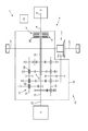
- numeral 1 indicates as a whole a road vehicle with hybrid propulsion provided with two front wheels 2 and two rear driving wheels 3, which receive torque from a hybrid propulsion system 4.
- the hybrid propulsion system 4 comprises an internal combustion engine 5, which is arranged in frontal position and is provided with a drive shaft 6, an automatic manual transmission 7 (commonly named "AMT"), which transmits the torque generated by the internal combustion engine 5 to the rear drive wheels 3, and a reversible electric machine 8 (i.e. an electric machine which can work either as electric engine, using electricity and generating mechanical torque, or as electric generator, using mechanical energy and generating electricity), which is mechanically connected to the transmission 7.
- AMT automatic manual transmission 7
- a reversible electric machine 8 i.e. an electric machine which can work either as electric engine, using electricity and generating mechanical torque, or as electric generator, using mechanical energy and generating electricity
- the transmission 7 comprises a transmission shaft 9, which on one end is angularly integral with the drive shaft 6, and on the other end is mechanically connected to a twin-clutch gearbox 10, which is arranged in rear position and transmits motion to the rear driving wheels 3 by means of two axles shafts 12, which receive motion from a differential 12.
- the reversible electric machine 8 is mechanically connected to the twin-clutch gearbox 10, as described in greater detail below, and is controlled by an electronic power converter 13 connected to an electric accumulation system 14, which is adapted to store electricity, and is provided with chemical batteries and/or supercapacitors.
- the twin-clutch gearbox 10 comprises two mutually coaxial, independent primary shafts 15 and 16, inserted within one another, and two coaxial clutches 17 and 18 arranged in series, each of which is adapted to connect a respective primary shaft 15 or 16 to the transmission shaft 9 (and thus to the drive shaft 6 of the thermal internal combustion engine 5). Furthermore, the twin-clutch gearbox 10 comprises two secondary shafts 19 and 20, which are both angularly integral with the input of the differential 11, which transmits motion to the rear driving wheels 3.
- the twin-clutch gearbox 10 shown in the figure 2 has seven forward gears indicated by Roman numerals (first gear I, second gear II, third gear III, fourth gear IV, fifth gear V, sixth gear VI and seventh gear VII) and one reverse gear (indicated by the letter R).
- the primary shafts 15 and 16 are mechanically coupled to the secondary shafts 19 and 20 by means of a plurality of gear pairs 21, each of which defines a respective gear, and comprises a primary gear which is mounted on a primary shaft 15 or 16 and a secondary gear, which is mounted on a secondary shaft 19 or 20 and permanently meshes with the primary gear.
- Each primary gear 8 is keyed onto a respective primary shaft 15 or 16 to rotate, again integrally, with the primary shaft 15 or 16 itself, and permanently meshes with the respective secondary gear; instead, each secondary gear is idly mounted on the respective secondary shaft 19 or 20.
- the twin-clutch gearbox 10 comprises a respective synchronizer 22 for each gear pair 21, which is mounted coaxially to respective secondary shaft 19 or 20, and is adapted to be actuated to engage the respective secondary gear 19 or 20 (i.e. to make the respective gear angularly integral with the secondary shaft 19 or 20).
- the electric machine 8 has a drive shaft 23, which is permanently connected to the primary shaft 15 so as to rotate, again integrally, with the primary shaft 15 itself.
- the primary shaft 15 is elongated on the side opposite to the clutches 17 and 18 in order to protrude from a gearbox casing 24; therefore, outside the gearbox 24, the primary shaft 15 is made integral (e.g. by butt jointing) to the shaft 23 of the electric machine 8.
- the vehicle 1 comprises a control unit 25, which superintends the operation of the propulsion system 4, and thus the operation of the thermal engine 5, of the transmission 7 and of the electric machine 8.
- the control unit 25 is connected to a temperature sensor which detects the temperature of a cooling liquid of the thermal engine 5.
- control unit 25 The methods used by the control unit 25 to start the thermal engine 5 when the vehicle 1 is stationary are described with reference to figure 3 .
- the thermal engine 5 when the vehicle 1 is standing, the thermal engine 5 must be normally started following a request for movement by the driver (i.e. the driver presses the accelerator pedal when requesting movement); therefore, in order to satisfy the motion requirement by the driver as quickly as possible, torque must be transmitted to the driving wheels 3 as rapidly as possible.
- the control unit 25 makes the electric machine 8 work as engine to generate the maximum possible torque; at the same time (or nearly at the same time, as described in greater detail below) the control unit 25 partially closes both clutches 17 and 18 so that both clutches 17 and 18 slip (i.e. work with a given relative slip between the two parts of each clutch 17 and 18) and the second gear II is engaged by making the corresponding synchronizer 22 connect the primary shaft 16 to the driving wheels 3 (obviously all the other gears are disengaged).
- the torque generated by the electric machine 8 (shown by a thick solid line in figure 3 ) is entirely transmitted by the clutch 17 to a basket 26 in common to the clutches 17 and 18; from the basket 26 in common to clutches 17 and 18 the torque generated by the electric machine 8 is divided partially towards the thermal engine 5 and partially towards the primary shaft 16, and thus towards the driving wheels 3.
- the part of torque addressed towards the thermal engine 5 is indicated by a thick dashed-and-dotted line, while the part of torque addressed towards the driving wheels 3 is indicated by a thick dashed line.
- the part of the driving torque generated by the electric machine 8 which is addressed towards the thermal engine 5 turns the engine shaft 6 determining the ignition of the thermal engine 5 itself in known manner. Instead, the part of the torque generated by the electric machine 8 which is addressed towards the driving wheels 3 turns the driving wheels 3 themselves determining the running of the vehicle 1.
- the distribution of the torque generated by the electric machine 8 between the thermal engine 5 and the driving wheels 3 is regulated by the degree of closure of the clutches 17 and 18; in other words, the degree of closure of the clutch 17 is regulated to regulate the part of torque addressed towards the thermal engine 5 (the more the clutch 17 is closed, the more driving torque generated by the electric machine 8 is addressed towards the thermal engine 5), and the degree of closing of the clutch 18 is regulated to regulate the part of torque addressed to the driving wheels 3 (the more the clutch 18 is closed, the higher is the part of torque generated by the electric machine 8 addressed to the driving wheels 3).
- the degree of closure of the clutch 17 is regulated to regulate the part of torque addressed to the thermal engine 5 according to the starting needs of the thermal engine 5 itself, while the degree of closure of the clutch 18 is regulated to regulate the part of torque addressed to the driving wheels 3 according to the motion requirements of the vehicle 1; the two regulation methods are not independent, because the available torque is limited by the performance of the electric machine 8, and thus an acceptable compromise must be found in every instant between the starting needs of the thermal engine 5 and the motion requirements of the vehicle 1.
- the essential need is to avoid sudden or even pulsating longitudinal acceleration variations of the vehicle 1, because this is extremely uncomfortable for the occupants of the vehicle 1.
- both clutches 17 and 18 are partially closed so that both clutches 17 and 18 slip; in this manner, the rotation speed of the electric machine 8, the rotation speed of the thermal engine 5, and the rotation speed of the driving wheels 3 are independent from one another. Consequently, the electric machine 8 may turn at the rotation speed which allows the generation of the maximum possible mechanical power (typically the nominal rotation speed of the electric machine 8), because during this step all the available power is needed to start the thermal engine 5 rapidly and to accelerate the vehicle 1; in other words, the rotation speed of the electric machine 8 is independent from the rotation speed of the drive wheels 3 and the rotation speed of the drive shaft 6 of the thermal engine 5 and thus may maximize the generation of the mechanical power.
- the maximum possible mechanical power typically the nominal rotation speed of the electric machine 8
- the drive shaft 6 of the thermal engine 5 is free to follow an optimal progression of the angular speed compatible with the concerned inertias (which in the case of a fractioned thermal engine 5 split into 8, 10 or 12 cylinders are high because of the cylinder counterpressure).
- the driving wheels 3 of the vehicle 1 are free to impart the required acceleration compatibly with the concerned inertias to the vehicle 1.
- the electric machine 8 may be temporarily overloaded with respect to the nominal performance to have the maximum possible power available; in other words, the intensity of the electric current supplied to the electric machine 8 is increased to overload the electric machine 8 by feeding the electric machine 8 itself with an electric current having an intensity which is higher than nominal intensity (i.e. than the maximum intensity which can be sustained in continued manner without damage) in order to have the electric machine 8 generating a mechanical power higher than the nominal mechanical power.
- the electric machine 8 before partially closing the clutches 17 and 18 the electric machine 8 is accelerated with no load to reach a required launch rotation speed; only when the electric machine 8 has reached the required launch rotation speed the clutches 17 and 18 are partially closed, as described above. In this manner, the torque (higher than nominal torque) generated by the electric machine 8 is entirely used to rotate the drive shaft 6 of the thermal engine 5, because the electric machine 8 (along with the parts of the transmission 7 angularly integral with the electric machine 8) was previously made to rotate.
- part of the kinetic energy possessed by the electric machine 8 (and by parts of the transmission 7 angularly integral with the electric machine 8) can be transferred to the drive shaft 6 of the thermal engine 5 and/or to the driving wheels 3; in other words, the electric machine 8 undergoes a deceleration which determines a transfer of part of the kinetic energy possessed by the electric machine 8 (and by the parts of the transmission 7 integrally angular with the electric machine 8) to the drive shaft 6 of the thermal engine 5 and/or to the driving wheels 3.
- the control unit 25 determines the temperature of the thermal engine 5 by reading the measurement provided by the temperature sensor of the cooling liquid of the thermal engine 5.
- the control unit 25 determines the overload of the electric machine 8 by determining the increased intensity of the electric current fed to the electric machine 8 with respect to nominal intensity according to the temperature of the thermal engine 5; in particular, the increase of the intensity of the electric current fed to the electric machine 8 with respect to nominal intensity is inversely proportional to the temperature of the thermal engine 5, thus the lower the temperature of the thermal engine 5, the higher the increase of intensity of the electric current fed to the electric machine 8 with respect to the nominal intensity, and vice versa. In other words, the lower the temperature of the thermal engine 5, the higher the starting torque to be applied to the drive shaft 6 of the thermal engine 5, and thus the higher the overload of the electric machine 8.
- the control unit 25 determines the launch rotation speed of the electric machine 8 (i.e. the rotation speed of the electric machine 8 in the closing instant of the clutch 15) according to the temperature of the thermal engine 5; in particular, the launch rotation speed is inversely proportional to the temperature of the thermal engine 5, and therefore the lower the temperature of the thermal engine 5, the higher the launch rotation speed.
- control unit 25 regulates both the launch rotation speed of the electric machine 8 when the clutch 15 is closed, and the overload entity of the electric machine 8 while/after closing the clutch 15 according to the temperature of the thermal engine 5 (i.e. the temperature of the cooling liquid of the thermal engine 5); in this manner, when the thermal engine 5 is "cold", i.e. the torque required for starting is higher due to the hydraulic resistance generated by the lubricant, the launch rotation speed of the electric machine 8 when the clutch 15 is closed can be increased and/or the overload intensity of the electric machine 8 can be increased.
- the control unit 25 before starting the thermal engine 5 the control unit 25 also determines the temperature of the electric machine 8, and thus determines the intensity of the electric current fed to the electric machine 8 with respect to the nominal intensity also according to the temperature of the electric machine 8.
- the control unit 25 may limit the electric machine 8 overload (typically by compensating the overload limitation of the electric machine 8 with a corresponding increase of the launch rotation speed) to prevent subjecting the electric machine 8 to excessive overheating, which could damage or overstress the electric insulation of the electric machine 8 itself. Consequently, beyond given threshold, the higher the temperature of the electric machine 8, the lower the increase of the intensity of the electric current fed to the electric machine 8 with respect to nominal intensity.
- the temperature of the electric machine 8 is estimated according to the temperature of the cooling liquid of the thermal engine 5 supplied by the temperature sensor. If the cooling circuit of the electric machine 8 is independent from the cooling circuit of the thermal engine 5, the temperature of the electric machine 8 is independently estimated by determining the temperature of the thermal engine 5 using a specific temperature sensor, or the temperature of the electric machine 8 is indirectly estimated by estimating an electric resistance of at least one stator winding of the electric machine 8 according to the voltage applied to the terminals of the stator winding and to the electric current which crosses the terminals of the stator winding, and thus estimating the temperature of the electric machine 8 according to the electric resistance of the stator winding of the electric machine 8.
- the above described starting method of the thermal engine 5 has many advantages.
- the above described method for starting the thermal engine 5 allows to rapidly and effectively start the thermal engine 5 in all conditions (i.e. both when the thermal engine 5 is “cold” and when the thermal engine 5 is “warm") without excessively stressing (i.e. stressing more than necessary) the components of the transmission 7, and in particular the electric machine 8.
- the driver and the other occupants of the vehicle 1 are not aware of the starting of the thermal engine 5 and do not experience any negative consequence (such as sudden or unexpected braking of the vehicle and/or the onset of longitudinal oscillations) during the starting of the thermal engine 5. Therefore, from the point of view of the driver and the other occupants of the vehicle 1 the starting of the thermal engine 5 is extremely comfortable.
- the above-described method for starting the thermal engine 5 is simple and cost-effective to be implemented also in an existing vehicle with hybrid propulsion because it does not require the installation of additional physical components with respect to those normally present and does not engage a considerable calculation power (therefore does not require an increase of power of the control unit 25).
Landscapes
- Engineering & Computer Science (AREA)
- Chemical & Material Sciences (AREA)
- Combustion & Propulsion (AREA)
- Transportation (AREA)
- Mechanical Engineering (AREA)
- Automation & Control Theory (AREA)
- Hybrid Electric Vehicles (AREA)
- Control Of Vehicle Engines Or Engines For Specific Uses (AREA)
Applications Claiming Priority (1)
| Application Number | Priority Date | Filing Date | Title |
|---|---|---|---|
| ITBO2009A000567A IT1395448B1 (it) | 2009-09-03 | 2009-09-03 | Metodo di avviamento di un motore termico di un veicolo con propulsione ibrida |
Publications (2)
| Publication Number | Publication Date |
|---|---|
| EP2292489A1 true EP2292489A1 (fr) | 2011-03-09 |
| EP2292489B1 EP2292489B1 (fr) | 2013-01-09 |
Family
ID=42062344
Family Applications (1)
| Application Number | Title | Priority Date | Filing Date |
|---|---|---|---|
| EP10174807A Active EP2292489B1 (fr) | 2009-09-03 | 2010-09-01 | Méthode de démarrage d'un moteur thermique d'un véhicule hybride |
Country Status (3)
| Country | Link |
|---|---|
| US (1) | US8386106B2 (fr) |
| EP (1) | EP2292489B1 (fr) |
| IT (1) | IT1395448B1 (fr) |
Cited By (6)
| Publication number | Priority date | Publication date | Assignee | Title |
|---|---|---|---|---|
| EP2511147A1 (fr) * | 2011-04-12 | 2012-10-17 | GETRAG Getriebe- und Zahnradfabrik Hermann Hagenmeyer GmbH & Cie KG | Procédé destiné au fonctionnement d'une chaîne cinématique hybride |
| WO2012156041A1 (fr) * | 2011-05-13 | 2012-11-22 | Audi Ag | Système de propulsion hybride pour véhicules automobiles |
| FR3013660A1 (fr) * | 2013-11-28 | 2015-05-29 | Renault Sa | Procede et systeme de demarrage d'un moteur thermique |
| RU2617251C1 (ru) * | 2014-11-06 | 2017-04-24 | Тойота Дзидося Кабусики Кайся | Контроллер для транспортного средства |
| EP3083356A4 (fr) * | 2013-12-16 | 2017-06-07 | BYD Company Limited | Procédé et système pour démarrer un moteur à combustion de véhicule hybride |
| WO2018065313A1 (fr) * | 2016-10-04 | 2018-04-12 | GETRAG B.V. & Co. KG | Procédé de démarrage d'un véhicule automobile |
Families Citing this family (10)
| Publication number | Priority date | Publication date | Assignee | Title |
|---|---|---|---|---|
| DE102011003080A1 (de) * | 2011-01-19 | 2012-07-19 | Robert Bosch Gmbh | Verfahren und Vorrichtung zum Betreiben einer Antriebsvorrichtung |
| KR101684500B1 (ko) * | 2011-12-06 | 2016-12-09 | 현대자동차 주식회사 | 하이브리드 차량의 엔진 제어 방법 |
| JP5874594B2 (ja) * | 2012-09-26 | 2016-03-02 | アイシン・エィ・ダブリュ株式会社 | 車両用駆動装置の制御装置 |
| JP6028492B2 (ja) * | 2012-09-26 | 2016-11-16 | 株式会社デンソー | ハイブリッド車のモータ制御装置 |
| DE102013000838A1 (de) * | 2013-01-21 | 2014-07-24 | Getrag Getriebe- Und Zahnradfabrik Hermann Hagenmeyer Gmbh & Cie Kg | Verfahren zum Halten eines Kraftfahrzeuges an einer Steigung |
| CN105082972A (zh) * | 2014-04-18 | 2015-11-25 | 比亚迪股份有限公司 | 动力传动系统及具有该动力传动系统的车辆 |
| KR101601176B1 (ko) * | 2014-09-26 | 2016-03-08 | 현대자동차주식회사 | 차량의 변속장치 |
| KR101637685B1 (ko) * | 2014-09-29 | 2016-07-08 | 현대자동차주식회사 | Amt 하이브리드 변속기 |
| DE102017214396A1 (de) * | 2017-08-18 | 2019-02-21 | Bayerische Motoren Werke Aktiengesellschaft | Hybridantriebsgetriebeeinheit sowie Verfahren zum Betreiben eines Fahrzeugs mit Hybridantrieb |
| CN115059550A (zh) * | 2022-05-31 | 2022-09-16 | 江门市大长江集团有限公司 | 发动机起动方法、控制设备、装置以及车辆 |
Citations (11)
| Publication number | Priority date | Publication date | Assignee | Title |
|---|---|---|---|---|
| US5337848A (en) | 1992-01-25 | 1994-08-16 | Mercedes-Benz Ag | Hybrid drive for a motor vehicle |
| GB2335404A (en) | 1998-03-21 | 1999-09-22 | Trevor Lee Proudler | Hybrid power plants for e.g. motor vehicles |
| US6354974B1 (en) | 1999-04-26 | 2002-03-12 | Luk Lamellen Und Kupplungsbau Gmbh | Power train for use in motor vehicles and the like |
| US20020088291A1 (en) * | 2001-01-10 | 2002-07-11 | Bowen Thomas C. | Twin clutch automated transmission with integrated transfer case |
| US20020117860A1 (en) | 1998-09-09 | 2002-08-29 | Luk Lamellen Und Kupplungsbau Beteiligungs Kg | Power train for a motor vehicle |
| DE10305639A1 (de) * | 2002-02-12 | 2004-03-25 | Aisin Seiki K.K., Kariya | Getriebeanordnung mit einer Antriebsquelle |
| US20050139035A1 (en) * | 2003-12-24 | 2005-06-30 | Hee Ra Lee | Double clutch transmission for a hybrid electric vehicle and method for operating the same |
| US20050155803A1 (en) | 2004-01-15 | 2005-07-21 | Peter Schiele | Method for controlling and regulating a powertrain of a hybrid vehicle and powertrain of a hybrid vehicle |
| WO2007131838A1 (fr) | 2006-05-12 | 2007-11-22 | Robert Bosch Gmbh | Procédé pour démarrer un moteur à combustion interne avec entraînement hybride |
| US20090017988A1 (en) | 2007-07-05 | 2009-01-15 | Luk Lamellen Und Kupplungsbau Beteiligungs Kg | Method for controlling a starting clutch |
| DE102007050659A1 (de) * | 2007-10-24 | 2009-04-30 | Zf Friedrichshafen Ag | Verfahren zum Betreiben eines Antriebsstrangs |
Family Cites Families (2)
| Publication number | Priority date | Publication date | Assignee | Title |
|---|---|---|---|---|
| US6455947B1 (en) * | 2001-02-14 | 2002-09-24 | Bae Systems Controls, Inc. | Power combining apparatus for hybrid electric vehicle |
| US7383902B2 (en) * | 2002-12-20 | 2008-06-10 | Hitachi, Ltd. | Hybrid car and control apparatus therefor, and hybrid four-wheel-drive car and control apparatus therefor |
-
2009
- 2009-09-03 IT ITBO2009A000567A patent/IT1395448B1/it active
-
2010
- 2010-09-01 EP EP10174807A patent/EP2292489B1/fr active Active
- 2010-09-03 US US12/875,739 patent/US8386106B2/en active Active
Patent Citations (11)
| Publication number | Priority date | Publication date | Assignee | Title |
|---|---|---|---|---|
| US5337848A (en) | 1992-01-25 | 1994-08-16 | Mercedes-Benz Ag | Hybrid drive for a motor vehicle |
| GB2335404A (en) | 1998-03-21 | 1999-09-22 | Trevor Lee Proudler | Hybrid power plants for e.g. motor vehicles |
| US20020117860A1 (en) | 1998-09-09 | 2002-08-29 | Luk Lamellen Und Kupplungsbau Beteiligungs Kg | Power train for a motor vehicle |
| US6354974B1 (en) | 1999-04-26 | 2002-03-12 | Luk Lamellen Und Kupplungsbau Gmbh | Power train for use in motor vehicles and the like |
| US20020088291A1 (en) * | 2001-01-10 | 2002-07-11 | Bowen Thomas C. | Twin clutch automated transmission with integrated transfer case |
| DE10305639A1 (de) * | 2002-02-12 | 2004-03-25 | Aisin Seiki K.K., Kariya | Getriebeanordnung mit einer Antriebsquelle |
| US20050139035A1 (en) * | 2003-12-24 | 2005-06-30 | Hee Ra Lee | Double clutch transmission for a hybrid electric vehicle and method for operating the same |
| US20050155803A1 (en) | 2004-01-15 | 2005-07-21 | Peter Schiele | Method for controlling and regulating a powertrain of a hybrid vehicle and powertrain of a hybrid vehicle |
| WO2007131838A1 (fr) | 2006-05-12 | 2007-11-22 | Robert Bosch Gmbh | Procédé pour démarrer un moteur à combustion interne avec entraînement hybride |
| US20090017988A1 (en) | 2007-07-05 | 2009-01-15 | Luk Lamellen Und Kupplungsbau Beteiligungs Kg | Method for controlling a starting clutch |
| DE102007050659A1 (de) * | 2007-10-24 | 2009-04-30 | Zf Friedrichshafen Ag | Verfahren zum Betreiben eines Antriebsstrangs |
Non-Patent Citations (1)
| Title |
|---|
| BERGER R ET AL: "ESG - Elektrisches Schaltgetriebe", ATZ AUTOMOBILTECHNISCHE ZEITSCHRIFT, VIEWEG PUBLISHING, WIESBADEN, DE, vol. 107, no. 6, 1 June 2005 (2005-06-01), pages 488 - 493,495, XP001519133, ISSN: 0001-2785 * |
Cited By (10)
| Publication number | Priority date | Publication date | Assignee | Title |
|---|---|---|---|---|
| EP2511147A1 (fr) * | 2011-04-12 | 2012-10-17 | GETRAG Getriebe- und Zahnradfabrik Hermann Hagenmeyer GmbH & Cie KG | Procédé destiné au fonctionnement d'une chaîne cinématique hybride |
| WO2012156041A1 (fr) * | 2011-05-13 | 2012-11-22 | Audi Ag | Système de propulsion hybride pour véhicules automobiles |
| FR3013660A1 (fr) * | 2013-11-28 | 2015-05-29 | Renault Sa | Procede et systeme de demarrage d'un moteur thermique |
| WO2015079006A1 (fr) * | 2013-11-28 | 2015-06-04 | Renault S.A.S | Procede et systeme de demarrage d'un moteur thermique |
| CN105848950B (zh) * | 2013-11-28 | 2019-07-09 | 雷诺两合公司 | 用于启动燃烧式发动机的方法和系统 |
| US10532735B2 (en) | 2013-11-28 | 2020-01-14 | Renault S.A.S. | Method and system for starting a combustion engine |
| EP3083356A4 (fr) * | 2013-12-16 | 2017-06-07 | BYD Company Limited | Procédé et système pour démarrer un moteur à combustion de véhicule hybride |
| US9889841B2 (en) | 2013-12-16 | 2018-02-13 | Byd Company Limited | Method and system for starting engine of hybrid vehicle |
| RU2617251C1 (ru) * | 2014-11-06 | 2017-04-24 | Тойота Дзидося Кабусики Кайся | Контроллер для транспортного средства |
| WO2018065313A1 (fr) * | 2016-10-04 | 2018-04-12 | GETRAG B.V. & Co. KG | Procédé de démarrage d'un véhicule automobile |
Also Published As
| Publication number | Publication date |
|---|---|
| US20110082609A1 (en) | 2011-04-07 |
| EP2292489B1 (fr) | 2013-01-09 |
| ITBO20090567A1 (it) | 2011-03-04 |
| US8386106B2 (en) | 2013-02-26 |
| IT1395448B1 (it) | 2012-09-21 |
Similar Documents
| Publication | Publication Date | Title |
|---|---|---|
| EP2292489B1 (fr) | Méthode de démarrage d'un moteur thermique d'un véhicule hybride | |
| US10232698B2 (en) | Mode transition control device for hybrid vehicle | |
| US10343509B2 (en) | Device for controlling driving force of hybrid vehicle | |
| US8060266B2 (en) | Mode changeover control device for a hybrid vehicle | |
| US6808470B2 (en) | Motor vehicle drive | |
| EP2594445B1 (fr) | Dispositif de commande de changement de vitesse pour système d'entraînement de véhicule hybride | |
| CN101209711B (zh) | 用于混合动力车辆的模式转换控制装置 | |
| EP2246230B1 (fr) | Méthode pour démarrer un moteur thermique d'un véhicule hybride | |
| EP2574515B1 (fr) | Dispositif de commande pour véhicule hybride | |
| US9216734B2 (en) | Control device | |
| JP5373371B2 (ja) | ハイブリッド電気自動車の制御装置 | |
| JP5747980B2 (ja) | ハイブリッド車両の制御装置 | |
| US20070056784A1 (en) | Engine starting control device for a hybrid vehicle | |
| EP1772301A2 (fr) | Système de commande de la traction du véhicule | |
| US10093166B2 (en) | Power generation control system for hybrid vehicle | |
| DE102007000672B4 (de) | Antriebsquellensteuerungsvorrichtung für ein Fahrzeug | |
| US20180141426A1 (en) | Mode transition control device for hybrid vehicle | |
| JP6374431B2 (ja) | 駆動制御機構および駆動制御装置 | |
| US20110048822A1 (en) | Method and device for controlling a creep operation of a vehicle with a hybrid drive | |
| JP3454172B2 (ja) | ハイブリッド車両の制御方法 | |
| EP3916269B1 (fr) | Dispositif de conduite de véhicule et véhicule hybride | |
| JP2020152241A (ja) | 車両の制御装置 | |
| KR20210014442A (ko) | 하이브리드 차량의 변속기 입력 토크 제어 방법 | |
| JP2023059718A (ja) | ハイブリッド式電動車両の制御装置 | |
| JP2012091571A (ja) | 車両の走行制御装置 |
Legal Events
| Date | Code | Title | Description |
|---|---|---|---|
| PUAI | Public reference made under article 153(3) epc to a published international application that has entered the european phase |
Free format text: ORIGINAL CODE: 0009012 |
|
| 17P | Request for examination filed |
Effective date: 20101112 |
|
| AK | Designated contracting states |
Kind code of ref document: A1 Designated state(s): AL AT BE BG CH CY CZ DE DK EE ES FI FR GB GR HR HU IE IS IT LI LT LU LV MC MK MT NL NO PL PT RO SE SI SK SM TR |
|
| AX | Request for extension of the european patent |
Extension state: BA ME RS |
|
| REG | Reference to a national code |
Ref country code: DE Ref legal event code: R079 Ref document number: 602010004502 Country of ref document: DE Free format text: PREVIOUS MAIN CLASS: B60W0010080000 Ipc: B60W0010060000 |
|
| RIC1 | Information provided on ipc code assigned before grant |
Ipc: B60W 10/06 20060101AFI20120601BHEP Ipc: B60W 10/02 20060101ALI20120601BHEP Ipc: B60W 30/192 20120101ALI20120601BHEP Ipc: B60K 6/547 20071001ALI20120601BHEP Ipc: B60W 10/08 20060101ALI20120601BHEP Ipc: B60W 20/00 20060101ALI20120601BHEP Ipc: B60W 10/113 20120101ALI20120601BHEP Ipc: B60K 6/36 20071001ALI20120601BHEP Ipc: B60K 6/48 20071001ALI20120601BHEP Ipc: B60W 30/18 20120101ALI20120601BHEP |
|
| GRAP | Despatch of communication of intention to grant a patent |
Free format text: ORIGINAL CODE: EPIDOSNIGR1 |
|
| GRAS | Grant fee paid |
Free format text: ORIGINAL CODE: EPIDOSNIGR3 |
|
| GRAA | (expected) grant |
Free format text: ORIGINAL CODE: 0009210 |
|
| AK | Designated contracting states |
Kind code of ref document: B1 Designated state(s): AL AT BE BG CH CY CZ DE DK EE ES FI FR GB GR HR HU IE IS IT LI LT LU LV MC MK MT NL NO PL PT RO SE SI SK SM TR |
|
| REG | Reference to a national code |
Ref country code: GB Ref legal event code: FG4D |
|
| RIN1 | Information on inventor provided before grant (corrected) |
Inventor name: FAVARETTO, FABRIZIO |
|
| REG | Reference to a national code |
Ref country code: AT Ref legal event code: REF Ref document number: 592544 Country of ref document: AT Kind code of ref document: T Effective date: 20130115 Ref country code: CH Ref legal event code: EP |
|
| REG | Reference to a national code |
Ref country code: IE Ref legal event code: FG4D |
|
| REG | Reference to a national code |
Ref country code: DE Ref legal event code: R096 Ref document number: 602010004502 Country of ref document: DE Effective date: 20130307 |
|
| PG25 | Lapsed in a contracting state [announced via postgrant information from national office to epo] |
Ref country code: SI Free format text: LAPSE BECAUSE OF FAILURE TO SUBMIT A TRANSLATION OF THE DESCRIPTION OR TO PAY THE FEE WITHIN THE PRESCRIBED TIME-LIMIT Effective date: 20130109 |
|
| REG | Reference to a national code |
Ref country code: NL Ref legal event code: VDEP Effective date: 20130109 |
|
| REG | Reference to a national code |
Ref country code: AT Ref legal event code: MK05 Ref document number: 592544 Country of ref document: AT Kind code of ref document: T Effective date: 20130109 |
|
| REG | Reference to a national code |
Ref country code: LT Ref legal event code: MG4D |
|
| PG25 | Lapsed in a contracting state [announced via postgrant information from national office to epo] |
Ref country code: LT Free format text: LAPSE BECAUSE OF FAILURE TO SUBMIT A TRANSLATION OF THE DESCRIPTION OR TO PAY THE FEE WITHIN THE PRESCRIBED TIME-LIMIT Effective date: 20130109 Ref country code: IS Free format text: LAPSE BECAUSE OF FAILURE TO SUBMIT A TRANSLATION OF THE DESCRIPTION OR TO PAY THE FEE WITHIN THE PRESCRIBED TIME-LIMIT Effective date: 20130509 Ref country code: BE Free format text: LAPSE BECAUSE OF FAILURE TO SUBMIT A TRANSLATION OF THE DESCRIPTION OR TO PAY THE FEE WITHIN THE PRESCRIBED TIME-LIMIT Effective date: 20130109 Ref country code: SE Free format text: LAPSE BECAUSE OF FAILURE TO SUBMIT A TRANSLATION OF THE DESCRIPTION OR TO PAY THE FEE WITHIN THE PRESCRIBED TIME-LIMIT Effective date: 20130109 Ref country code: ES Free format text: LAPSE BECAUSE OF FAILURE TO SUBMIT A TRANSLATION OF THE DESCRIPTION OR TO PAY THE FEE WITHIN THE PRESCRIBED TIME-LIMIT Effective date: 20130420 Ref country code: NO Free format text: LAPSE BECAUSE OF FAILURE TO SUBMIT A TRANSLATION OF THE DESCRIPTION OR TO PAY THE FEE WITHIN THE PRESCRIBED TIME-LIMIT Effective date: 20130409 Ref country code: BG Free format text: LAPSE BECAUSE OF FAILURE TO SUBMIT A TRANSLATION OF THE DESCRIPTION OR TO PAY THE FEE WITHIN THE PRESCRIBED TIME-LIMIT Effective date: 20130409 Ref country code: AT Free format text: LAPSE BECAUSE OF FAILURE TO SUBMIT A TRANSLATION OF THE DESCRIPTION OR TO PAY THE FEE WITHIN THE PRESCRIBED TIME-LIMIT Effective date: 20130109 |
|
| PG25 | Lapsed in a contracting state [announced via postgrant information from national office to epo] |
Ref country code: GR Free format text: LAPSE BECAUSE OF FAILURE TO SUBMIT A TRANSLATION OF THE DESCRIPTION OR TO PAY THE FEE WITHIN THE PRESCRIBED TIME-LIMIT Effective date: 20130410 Ref country code: PL Free format text: LAPSE BECAUSE OF FAILURE TO SUBMIT A TRANSLATION OF THE DESCRIPTION OR TO PAY THE FEE WITHIN THE PRESCRIBED TIME-LIMIT Effective date: 20130109 Ref country code: PT Free format text: LAPSE BECAUSE OF FAILURE TO SUBMIT A TRANSLATION OF THE DESCRIPTION OR TO PAY THE FEE WITHIN THE PRESCRIBED TIME-LIMIT Effective date: 20130509 Ref country code: FI Free format text: LAPSE BECAUSE OF FAILURE TO SUBMIT A TRANSLATION OF THE DESCRIPTION OR TO PAY THE FEE WITHIN THE PRESCRIBED TIME-LIMIT Effective date: 20130109 Ref country code: LV Free format text: LAPSE BECAUSE OF FAILURE TO SUBMIT A TRANSLATION OF THE DESCRIPTION OR TO PAY THE FEE WITHIN THE PRESCRIBED TIME-LIMIT Effective date: 20130109 Ref country code: NL Free format text: LAPSE BECAUSE OF FAILURE TO SUBMIT A TRANSLATION OF THE DESCRIPTION OR TO PAY THE FEE WITHIN THE PRESCRIBED TIME-LIMIT Effective date: 20130109 |
|
| PG25 | Lapsed in a contracting state [announced via postgrant information from national office to epo] |
Ref country code: HR Free format text: LAPSE BECAUSE OF FAILURE TO SUBMIT A TRANSLATION OF THE DESCRIPTION OR TO PAY THE FEE WITHIN THE PRESCRIBED TIME-LIMIT Effective date: 20130109 |
|
| PG25 | Lapsed in a contracting state [announced via postgrant information from national office to epo] |
Ref country code: CZ Free format text: LAPSE BECAUSE OF FAILURE TO SUBMIT A TRANSLATION OF THE DESCRIPTION OR TO PAY THE FEE WITHIN THE PRESCRIBED TIME-LIMIT Effective date: 20130109 Ref country code: EE Free format text: LAPSE BECAUSE OF FAILURE TO SUBMIT A TRANSLATION OF THE DESCRIPTION OR TO PAY THE FEE WITHIN THE PRESCRIBED TIME-LIMIT Effective date: 20130109 Ref country code: SK Free format text: LAPSE BECAUSE OF FAILURE TO SUBMIT A TRANSLATION OF THE DESCRIPTION OR TO PAY THE FEE WITHIN THE PRESCRIBED TIME-LIMIT Effective date: 20130109 Ref country code: DK Free format text: LAPSE BECAUSE OF FAILURE TO SUBMIT A TRANSLATION OF THE DESCRIPTION OR TO PAY THE FEE WITHIN THE PRESCRIBED TIME-LIMIT Effective date: 20130109 Ref country code: RO Free format text: LAPSE BECAUSE OF FAILURE TO SUBMIT A TRANSLATION OF THE DESCRIPTION OR TO PAY THE FEE WITHIN THE PRESCRIBED TIME-LIMIT Effective date: 20130109 |
|
| PLBE | No opposition filed within time limit |
Free format text: ORIGINAL CODE: 0009261 |
|
| STAA | Information on the status of an ep patent application or granted ep patent |
Free format text: STATUS: NO OPPOSITION FILED WITHIN TIME LIMIT |
|
| PG25 | Lapsed in a contracting state [announced via postgrant information from national office to epo] |
Ref country code: CY Free format text: LAPSE BECAUSE OF FAILURE TO SUBMIT A TRANSLATION OF THE DESCRIPTION OR TO PAY THE FEE WITHIN THE PRESCRIBED TIME-LIMIT Effective date: 20130109 |
|
| 26N | No opposition filed |
Effective date: 20131010 |
|
| REG | Reference to a national code |
Ref country code: DE Ref legal event code: R097 Ref document number: 602010004502 Country of ref document: DE Effective date: 20131010 |
|
| PG25 | Lapsed in a contracting state [announced via postgrant information from national office to epo] |
Ref country code: MC Free format text: LAPSE BECAUSE OF FAILURE TO SUBMIT A TRANSLATION OF THE DESCRIPTION OR TO PAY THE FEE WITHIN THE PRESCRIBED TIME-LIMIT Effective date: 20130109 |
|
| REG | Reference to a national code |
Ref country code: FR Ref legal event code: ST Effective date: 20140530 |
|
| REG | Reference to a national code |
Ref country code: IE Ref legal event code: MM4A |
|
| PG25 | Lapsed in a contracting state [announced via postgrant information from national office to epo] |
Ref country code: IE Free format text: LAPSE BECAUSE OF NON-PAYMENT OF DUE FEES Effective date: 20130901 |
|
| PG25 | Lapsed in a contracting state [announced via postgrant information from national office to epo] |
Ref country code: FR Free format text: LAPSE BECAUSE OF NON-PAYMENT OF DUE FEES Effective date: 20130930 |
|
| REG | Reference to a national code |
Ref country code: CH Ref legal event code: PL |
|
| PG25 | Lapsed in a contracting state [announced via postgrant information from national office to epo] |
Ref country code: SM Free format text: LAPSE BECAUSE OF FAILURE TO SUBMIT A TRANSLATION OF THE DESCRIPTION OR TO PAY THE FEE WITHIN THE PRESCRIBED TIME-LIMIT Effective date: 20130109 |
|
| PG25 | Lapsed in a contracting state [announced via postgrant information from national office to epo] |
Ref country code: MT Free format text: LAPSE BECAUSE OF FAILURE TO SUBMIT A TRANSLATION OF THE DESCRIPTION OR TO PAY THE FEE WITHIN THE PRESCRIBED TIME-LIMIT Effective date: 20130109 Ref country code: TR Free format text: LAPSE BECAUSE OF FAILURE TO SUBMIT A TRANSLATION OF THE DESCRIPTION OR TO PAY THE FEE WITHIN THE PRESCRIBED TIME-LIMIT Effective date: 20130109 |
|
| PG25 | Lapsed in a contracting state [announced via postgrant information from national office to epo] |
Ref country code: HU Free format text: LAPSE BECAUSE OF FAILURE TO SUBMIT A TRANSLATION OF THE DESCRIPTION OR TO PAY THE FEE WITHIN THE PRESCRIBED TIME-LIMIT; INVALID AB INITIO Effective date: 20100901 Ref country code: LU Free format text: LAPSE BECAUSE OF NON-PAYMENT OF DUE FEES Effective date: 20130901 Ref country code: MK Free format text: LAPSE BECAUSE OF FAILURE TO SUBMIT A TRANSLATION OF THE DESCRIPTION OR TO PAY THE FEE WITHIN THE PRESCRIBED TIME-LIMIT Effective date: 20130109 Ref country code: CH Free format text: LAPSE BECAUSE OF NON-PAYMENT OF DUE FEES Effective date: 20140930 Ref country code: LI Free format text: LAPSE BECAUSE OF NON-PAYMENT OF DUE FEES Effective date: 20140930 |
|
| PG25 | Lapsed in a contracting state [announced via postgrant information from national office to epo] |
Ref country code: AL Free format text: LAPSE BECAUSE OF FAILURE TO SUBMIT A TRANSLATION OF THE DESCRIPTION OR TO PAY THE FEE WITHIN THE PRESCRIBED TIME-LIMIT Effective date: 20130109 |
|
| RIC2 | Information provided on ipc code assigned after grant |
Ipc: B60W 30/192 20120101ALI20120601BHEP Ipc: B60W 20/00 20160101ALI20120601BHEP Ipc: B60W 10/02 20060101ALI20120601BHEP Ipc: B60W 10/06 20060101AFI20120601BHEP Ipc: B60W 30/18 20120101ALI20120601BHEP Ipc: B60W 10/113 20120101ALI20120601BHEP Ipc: B60K 6/547 20071001ALI20120601BHEP Ipc: B60K 6/48 20071001ALI20120601BHEP Ipc: B60W 10/08 20060101ALI20120601BHEP Ipc: B60K 6/36 20071001ALI20120601BHEP |
|
| P01 | Opt-out of the competence of the unified patent court (upc) registered |
Effective date: 20230525 |
|
| PGFP | Annual fee paid to national office [announced via postgrant information from national office to epo] |
Ref country code: IT Payment date: 20230911 Year of fee payment: 14 Ref country code: GB Payment date: 20230926 Year of fee payment: 14 |
|
| PGFP | Annual fee paid to national office [announced via postgrant information from national office to epo] |
Ref country code: DE Payment date: 20230928 Year of fee payment: 14 |