EP2292372A2 - Verfahren zur Herstellung eines Lochs unter Verwendung verschiedener Laserstellungen - Google Patents
Verfahren zur Herstellung eines Lochs unter Verwendung verschiedener Laserstellungen Download PDFInfo
- Publication number
- EP2292372A2 EP2292372A2 EP10002655A EP10002655A EP2292372A2 EP 2292372 A2 EP2292372 A2 EP 2292372A2 EP 10002655 A EP10002655 A EP 10002655A EP 10002655 A EP10002655 A EP 10002655A EP 2292372 A2 EP2292372 A2 EP 2292372A2
- Authority
- EP
- European Patent Office
- Prior art keywords
- remainder
- laser
- diffuser
- laser beam
- iii
- Prior art date
- Legal status (The legal status is an assumption and is not a legal conclusion. Google has not performed a legal analysis and makes no representation as to the accuracy of the status listed.)
- Granted
Links
- 238000000034 method Methods 0.000 title claims abstract description 28
- 239000000758 substrate Substances 0.000 claims abstract description 17
- 238000004519 manufacturing process Methods 0.000 claims description 22
- 238000001816 cooling Methods 0.000 claims description 19
- 239000010410 layer Substances 0.000 description 13
- PXHVJJICTQNCMI-UHFFFAOYSA-N Nickel Chemical compound [Ni] PXHVJJICTQNCMI-UHFFFAOYSA-N 0.000 description 8
- 239000000463 material Substances 0.000 description 8
- 239000012720 thermal barrier coating Substances 0.000 description 7
- 238000000576 coating method Methods 0.000 description 6
- 238000002485 combustion reaction Methods 0.000 description 6
- 229910000601 superalloy Inorganic materials 0.000 description 6
- 229910017052 cobalt Inorganic materials 0.000 description 5
- 239000010941 cobalt Substances 0.000 description 5
- GUTLYIVDDKVIGB-UHFFFAOYSA-N cobalt atom Chemical compound [Co] GUTLYIVDDKVIGB-UHFFFAOYSA-N 0.000 description 5
- 239000013078 crystal Substances 0.000 description 5
- 238000005260 corrosion Methods 0.000 description 3
- 230000003993 interaction Effects 0.000 description 3
- 229910052759 nickel Inorganic materials 0.000 description 3
- 238000007711 solidification Methods 0.000 description 3
- 230000008023 solidification Effects 0.000 description 3
- XEEYBQQBJWHFJM-UHFFFAOYSA-N Iron Chemical compound [Fe] XEEYBQQBJWHFJM-UHFFFAOYSA-N 0.000 description 2
- 229910045601 alloy Inorganic materials 0.000 description 2
- 239000000956 alloy Substances 0.000 description 2
- BRPQOXSCLDDYGP-UHFFFAOYSA-N calcium oxide Chemical compound [O-2].[Ca+2] BRPQOXSCLDDYGP-UHFFFAOYSA-N 0.000 description 2
- 239000000292 calcium oxide Substances 0.000 description 2
- ODINCKMPIJJUCX-UHFFFAOYSA-N calcium oxide Inorganic materials [Ca]=O ODINCKMPIJJUCX-UHFFFAOYSA-N 0.000 description 2
- 238000005266 casting Methods 0.000 description 2
- 239000002826 coolant Substances 0.000 description 2
- 230000007797 corrosion Effects 0.000 description 2
- 238000005566 electron beam evaporation Methods 0.000 description 2
- 229910052735 hafnium Inorganic materials 0.000 description 2
- VBJZVLUMGGDVMO-UHFFFAOYSA-N hafnium atom Chemical compound [Hf] VBJZVLUMGGDVMO-UHFFFAOYSA-N 0.000 description 2
- 239000000395 magnesium oxide Substances 0.000 description 2
- CPLXHLVBOLITMK-UHFFFAOYSA-N magnesium oxide Inorganic materials [Mg]=O CPLXHLVBOLITMK-UHFFFAOYSA-N 0.000 description 2
- AXZKOIWUVFPNLO-UHFFFAOYSA-N magnesium;oxygen(2-) Chemical compound [O-2].[Mg+2] AXZKOIWUVFPNLO-UHFFFAOYSA-N 0.000 description 2
- 239000000203 mixture Substances 0.000 description 2
- 230000003647 oxidation Effects 0.000 description 2
- 238000007254 oxidation reaction Methods 0.000 description 2
- 230000008569 process Effects 0.000 description 2
- 229910052710 silicon Inorganic materials 0.000 description 2
- 239000010703 silicon Substances 0.000 description 2
- 239000007787 solid Substances 0.000 description 2
- 230000007704 transition Effects 0.000 description 2
- 229910052727 yttrium Inorganic materials 0.000 description 2
- VWQVUPCCIRVNHF-UHFFFAOYSA-N yttrium atom Chemical compound [Y] VWQVUPCCIRVNHF-UHFFFAOYSA-N 0.000 description 2
- YPFNIPKMNMDDDB-UHFFFAOYSA-K 2-[2-[bis(carboxylatomethyl)amino]ethyl-(2-hydroxyethyl)amino]acetate;iron(3+) Chemical compound [Fe+3].OCCN(CC([O-])=O)CCN(CC([O-])=O)CC([O-])=O YPFNIPKMNMDDDB-UHFFFAOYSA-K 0.000 description 1
- 241000191291 Abies alba Species 0.000 description 1
- 239000008186 active pharmaceutical agent Substances 0.000 description 1
- 230000001154 acute effect Effects 0.000 description 1
- 239000002318 adhesion promoter Substances 0.000 description 1
- 239000000919 ceramic Substances 0.000 description 1
- 230000008859 change Effects 0.000 description 1
- 239000011248 coating agent Substances 0.000 description 1
- 230000001419 dependent effect Effects 0.000 description 1
- 238000010894 electron beam technology Methods 0.000 description 1
- 239000012530 fluid Substances 0.000 description 1
- 238000005242 forging Methods 0.000 description 1
- 239000000446 fuel Substances 0.000 description 1
- 238000000608 laser ablation Methods 0.000 description 1
- 239000007788 liquid Substances 0.000 description 1
- 238000003754 machining Methods 0.000 description 1
- 239000000155 melt Substances 0.000 description 1
- 229910001092 metal group alloy Inorganic materials 0.000 description 1
- 239000007769 metal material Substances 0.000 description 1
- 238000003801 milling Methods 0.000 description 1
- TWNQGVIAIRXVLR-UHFFFAOYSA-N oxo(oxoalumanyloxy)alumane Chemical compound O=[Al]O[Al]=O TWNQGVIAIRXVLR-UHFFFAOYSA-N 0.000 description 1
- SIWVEOZUMHYXCS-UHFFFAOYSA-N oxo(oxoyttriooxy)yttrium Chemical compound O=[Y]O[Y]=O SIWVEOZUMHYXCS-UHFFFAOYSA-N 0.000 description 1
- 238000007750 plasma spraying Methods 0.000 description 1
- 238000010248 power generation Methods 0.000 description 1
- 239000011253 protective coating Substances 0.000 description 1
- 230000001681 protective effect Effects 0.000 description 1
- 239000011241 protective layer Substances 0.000 description 1
- 229910052761 rare earth metal Inorganic materials 0.000 description 1
- 150000002910 rare earth metals Chemical class 0.000 description 1
- 238000009419 refurbishment Methods 0.000 description 1
- 238000005488 sandblasting Methods 0.000 description 1
- 229910052706 scandium Inorganic materials 0.000 description 1
- SIXSYDAISGFNSX-UHFFFAOYSA-N scandium atom Chemical compound [Sc] SIXSYDAISGFNSX-UHFFFAOYSA-N 0.000 description 1
- 230000035939 shock Effects 0.000 description 1
- 230000035882 stress Effects 0.000 description 1
- 239000000126 substance Substances 0.000 description 1
- 230000008646 thermal stress Effects 0.000 description 1
- RUDFQVOCFDJEEF-UHFFFAOYSA-N yttrium(III) oxide Inorganic materials [O-2].[O-2].[O-2].[Y+3].[Y+3] RUDFQVOCFDJEEF-UHFFFAOYSA-N 0.000 description 1
Images


Classifications
-
- B—PERFORMING OPERATIONS; TRANSPORTING
- B23—MACHINE TOOLS; METAL-WORKING NOT OTHERWISE PROVIDED FOR
- B23K—SOLDERING OR UNSOLDERING; WELDING; CLADDING OR PLATING BY SOLDERING OR WELDING; CUTTING BY APPLYING HEAT LOCALLY, e.g. FLAME CUTTING; WORKING BY LASER BEAM
- B23K26/00—Working by laser beam, e.g. welding, cutting or boring
- B23K26/36—Removing material
- B23K26/38—Removing material by boring or cutting
- B23K26/382—Removing material by boring or cutting by boring
- B23K26/389—Removing material by boring or cutting by boring of fluid openings, e.g. nozzles, jets
-
- B—PERFORMING OPERATIONS; TRANSPORTING
- B23—MACHINE TOOLS; METAL-WORKING NOT OTHERWISE PROVIDED FOR
- B23K—SOLDERING OR UNSOLDERING; WELDING; CLADDING OR PLATING BY SOLDERING OR WELDING; CUTTING BY APPLYING HEAT LOCALLY, e.g. FLAME CUTTING; WORKING BY LASER BEAM
- B23K26/00—Working by laser beam, e.g. welding, cutting or boring
- B23K26/02—Positioning or observing the workpiece, e.g. with respect to the point of impact; Aligning, aiming or focusing the laser beam
- B23K26/06—Shaping the laser beam, e.g. by masks or multi-focusing
- B23K26/062—Shaping the laser beam, e.g. by masks or multi-focusing by direct control of the laser beam
- B23K26/0622—Shaping the laser beam, e.g. by masks or multi-focusing by direct control of the laser beam by shaping pulses
Definitions
- the invention relates to a method for producing a hole in which the angular position of the laser relative to the substrate is changed discontinuously during processing.
- the use of the laser to make holes in substrates is known in which the laser is moved across the surface.
- the EP 0 950 463 A1 discloses that a laser beam rotates about an axis to first make the diffuser of a film cooling hole.
- the basic idea of the invention is therefore to divide the total volume of the hole to be produced into partial volumes and to form these in individual production steps. First, an inner portion is generated. A remainder remains to form the diffuser of the hole. The component material of a few individual partial volumes of this remainder is removed by traversing in each case one lateral flank of the bore with the laser beam.
- the laser beam is preferably aligned so that it encloses an angle of greater than 8 ° with the worn flank. Since the laser beam is not directed close to and parallel to the already formed flank of the bore on the component surface during the production of the bore, it is impossible that there is an impermissible interaction between the laser beam and the flank. Furthermore, the division of the total volume of the bore into several sub-volumes allows complex bore geometries to be formed.
- the laser beam is aligned so that it with the trailing edge an angle greater than 10 ° and less than 90 °, preferably greater than 15 ° and less than 80 ° and more preferably greater than 20 ° and smaller 60 °. Particularly preferred is an angle of 9 °.
- a laser beam with variable pulse width can be used become.
- the pulse width can be in the range from 50ns to 800ns, preferably from 70ns to 600ns and especially from 200ns to 500ns. Particularly preferred is a pulse width of 400ns.
- the component material can be evaporated very quickly. This is particularly advantageous for the manufacture of the diffuser.
- a laser beam with a frequency in the range of 20 kHz to 40 kHz, preferably from 25 kHz to 35 kHz and in particular from 28 kHz to 32 kHz can be directed to the component surface. This is particularly advantageous for the manufacture of the diffuser.
- a preferred embodiment of the invention provides to manufacture a bore in a turbine component, in particular in a turbine blade.
- the bore may in particular be a complete cooling air bore or a diffuser opening of a cooling air bore.
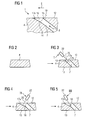
- FIG. 1 a hole 1 in a substrate 4 is shown.
- the substrate 4 is a nickel- or cobalt-based superalloy, in particular in turbine components such as turbine blades 120, 130 FIG. 12 ,
- the hole 1 is continuous (no blind hole).
- the film cooling hole 1 is overflowed in an overflow direction 9 of a hot gas.
- An outflow direction 8 of a cooling medium from the film cooling hole 1 and the overflow 9 form an acute angle with each other.
- the film cooling hole 1 has at least two differently shaped sections 7, 10, in particular it has only two sections 7, 10.
- the first portion is an inner portion 7 which is preferably cylindrical or rotationally symmetrical in cross section or preferably has at least one constant cross section in an outflow direction 8.
- a perpendicular 19 on the inner surface 17a intersects an opposing portion 15 in the substrate 4 on the surface 12th
- a laser 22 is used by way of example as a processing machine.
- the method begins with the provision of the substrate 4 (FIG. Fig. 2 ), which is then processed with a laser 22 or electron beam source in a first angular position (I), preferably the laser position (I).
- the angle of the angular positions I, II, III is defined by a middle line of a laser beam 25 and the surface 12 around the film cooling hole 1.
- the inner portion 7 is produced from the surface 12 to the opposite inner surface 13 of the substrate 4 (in the case of turbine blades in the cavity) ( Fig. 3 ).
- the laser 22 does not have to be moved.
- a remainder 16 remains in the hole 1 to be produced in order to finish the diffuser 10 ( Fig. 3 ).
- the inner portion 7 is completed.
- a first partial volume of the remainder 16 in a further step ( Fig. 4 ) and in a second laser position II, which is different from the first laser position I, a first partial volume of the remainder 16, a left partial volume 28 (FIG. Fig. 6-9 ) as the first portion of the still to be removed remainder 16 for the diffuser 10 removed.
- the angular position of the laser 22 relative to the surface of the flank has changed in the position II compared to the angular position I.
- the laser 22 is moved, preferably via the right flank 17b of the remainder 16, until a left flank 17a of the diffuser 10 is exposed.
- the method of the laser 22 does not represent any other angular position.
- laser parameters such as pulse lengths are preferably used as in the first laser position I.
- the angular position III of the laser 22 is different from the position II, in particular also from the angular position I.
- the angular positions I, II, III of the laser 22 preferably correspond to the partial steps.
- the production or the change of the laser positions I, II, III of the laser 22 relative to the substrate 4 is due to the fact that a laser 22 can not be used if a cut surface is to be made parallel to the laser beam direction, since the laser beam cone scatters 10 °, wherein the cone must not overlap with a final contour of the one area to be produced.
- the complex process steps give outstanding results as compared to using the laser / lasers in a single center position of II and III or only in position I.
- two lasers may also preferably be used if necessary, in particular for the manufacture of the diffuser 10, in which other parameters are preferably used for the second laser, so that the lasers 22 have different performance characteristics (power, pulse duration, frequency, .. .) exhibit.
- the laser beam is aligned in such a way that it encloses an angle of greater than 10 ° and less than 90 °, preferably greater than 15 ° and less than 80 °, and particularly preferably greater than 20 ° and less than 60 °, with the trailing edge. Particularly preferred is an angle of 9 °.
- a pulsed laser beam In this case, a laser beam with variable pulse width can be used.
- the pulse width can be in the range from 50ns to 800ns, preferably from 70ns to 600ns and especially from 200ns to 500ns. Particularly preferred is a pulse width of 400ns.
- the component material can be evaporated very quickly. This is particularly advantageous for the production of the diffuser 10, ie in the angular positions II, III.
- these pulse widths are not used in the angular position I.
- a laser beam with a frequency in the range of 20 kHz to 40 kHz, preferably from 25 kHz to 35 kHz and in particular from 28 kHz to 32 kHz can be directed to the component surface.
- This is particularly advantageous for the production of the diffuser 10, ie in the angular positions II, III.
- these frequencies are not used in the angular position I.
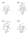
- FIG. 6 shows the rest 16 after FIG. 3 , wherein the remainder 16 is indicated by right and left laterally delimiting flanks 17a and 17b with dashed lines. Also with a dashed line, the total volume of the residue 16 to be removed is divided into a left 28 and a right 18 partial volume.
- the production of the left partial volume 28 is in the FIG. 7 shown and the FIG. 8 illustrates that of the right partial volume 18.
- a laser beam 25 is emitted by a laser 22 onto the component surface.
- the laser 22 is aligned so that the laser beam 25 with the left flank 17a forms an angle preferably greater than 5 ° and first encounters the immediately adjacent to the left flank 17 region of the left part of the volume 13, where it evaporates a portion of the component material.
- the laser beam 25 is further directed to the component surface until it reaches the left flank 17a. Then, the laser 22 is moved to the right in the drawing so that the laser beam 25 impinges on still existing in the sub-volume 13 component material, which in turn is evaporated to the left flank 17 a. In this way, the entire edge 17a of the partial volume 13 is traversed with the laser beam 25.
- the laser 22 is rotated counterclockwise and aligned so that the laser beam 25 with the right flank 17 b forms an angle greater than 8 ° and initially on the right Flank 17b adjacent region of the right sub-volume 18 impinges, where it evaporates a portion of the component material. Subsequently, in the manner already described, the right flank 17b is traversed with the laser beam 25, in order also to remove the right subvolume 18 (FIG. Fig. 8 ).
- FIG. 9 shows the rest 16 of the FIG. 2 in a schematic representation, wherein here an alternative hole geometry is indicated, which is defined by laterally delimiting flanks 17a and 17b.
- this alternative bore geometry the partial volumes 28 and 18 are arranged one above the other, wherein the partial volume 18 preferably adjoins the outer surface 12 of the component 1 with the tip.
- the production of the film cooling hole can also be carried out as described above if a metallic adhesion promoter layer, preferably of the MCrAlY type, is present on the substrate 4 and / or a ceramic layer is present on an MCrAlY layer or on the substrate 4.
- a metallic adhesion promoter layer preferably of the MCrAlY type
- the FIG. 10 shows by way of example a gas turbine 100 in a longitudinal partial section.
- the gas turbine 100 has inside a rotatably mounted about a rotation axis 102 rotor 103 with a shaft 101, which is also referred to as a turbine runner.
- a compressor 105 for example, a toroidal combustion chamber 110, in particular annular combustion chamber, with a plurality of coaxially arranged burners 107, a turbine 108 and the exhaust housing 109th
- the annular combustion chamber 110 communicates with an annular annular hot gas channel 111, for example.
- Each turbine stage 112 is formed, for example, from two blade rings. As seen in the direction of flow of a working medium 113, in the hot gas channel 111 of a row of guide vanes 115, a series 125 formed of rotor blades 120 follows.
- the guide vanes 130 are fastened to an inner housing 138 of a stator 143, whereas the moving blades 120 of a row 125 are attached to the rotor 103 by means of a turbine disk 133, for example. Coupled to the rotor 103 is a generator or work machine (not shown).
- air 105 is sucked in and compressed by the compressor 105 through the intake housing 104.
- the compressed air provided at the turbine-side end of the compressor 105 is supplied to the burners 107 where it is mixed with a fuel.
- the mixture is then burned to form the working fluid 113 in the combustion chamber 110.
- the working medium 113 flows along the hot gas channel 111 past the guide vanes 130 and the rotor blades 120.
- the working medium 113 expands in a pulse-transmitting manner, so that the rotor blades 120 drive the rotor 103 and drive the machine coupled to it.
- the components exposed to the hot working medium 113 are subject to thermal loads during operation of the gas turbine 100.
- the guide vanes 130 and rotor blades 120 of the first turbine stage 112, viewed in the flow direction of the working medium 113, are subjected to the greatest thermal stress in addition to the heat shield elements lining the annular combustion chamber 110. To withstand the prevailing temperatures, they can be cooled by means of a coolant.
- substrates of the components can have a directional structure, ie they are monocrystalline (SX structure) or have only longitudinal grains (DS structure).
- As the material for the components, in particular for the turbine blade 120, 130 and components of the combustion chamber 110 for example, iron-, nickel- or cobalt-based superalloys are used. Such superalloys are for example from EP 1 204 776 B1 .
- EP 1 306 454 EP 1 319 729 A1 .
- the blades 120, 130 may be anti-corrosion coatings (MCrAlX; M is at least one element of the group iron (Fe), cobalt (Co), nickel (Ni), X is an active element and is yttrium (Y) and / or silicon , Scandium (Sc) and / or at least one element of the rare earth or hafnium).
- M is at least one element of the group iron (Fe), cobalt (Co), nickel (Ni)
- X is an active element and is yttrium (Y) and / or silicon , Scandium (Sc) and / or at least one element of the rare earth or hafnium).
- Such alloys are known from the EP 0 486 489 B1 .
- EP 0 786 017 B1 EP 0 786 017 B1 .
- EP 0 412 397 B1 or EP 1 306 454 A1 On the MCrAlX may still be present a thermal barrier coating, and consists for example of ZrO 2 , Y 2 O 3 -ZrO 2 , that is, it is not, partially or completely stabilized by yttria and / or calcium oxide and / or magnesium oxide.
- suitable coating processes such as electron beam evaporation (EB-PVD), stalk-shaped grains are produced in the thermal barrier coating.
- the vane 130 has a guide vane foot (not shown here) facing the inner casing 138 of the turbine 108 and a vane head opposite the vane root.
- the vane head faces the rotor 103 and fixed to a mounting ring 140 of the stator 143.
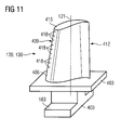
- FIG. 11 shows a perspective view of a blade 120 or guide vane 130 of a turbomachine, which extends along a longitudinal axis 121.
- the turbomachine may be a gas turbine of an aircraft or a power plant for power generation, a steam turbine or a compressor.
- the blade 120, 130 has along the longitudinal axis 121 consecutively a fastening region 400, a blade platform 403 adjacent thereto and an airfoil 406 and a blade tip 415.
- the blade 130 may have at its blade tip 415 another platform (not shown).
- a blade root 183 is formed, which serves for attachment of the blades 120, 130 to a shaft or a disc (not shown).
- the blade root 183 is designed, for example, as a hammer head. Other designs as Christmas tree or Schwalbenschwanzfuß are possible.
- the blade 120, 130 has a leading edge 409 and a trailing edge 412 for a medium flowing past the airfoil 406.
- blades 120, 130 for example, solid metallic materials, in particular superalloys, are used in all regions 400, 403, 406 of the blade 120, 130.
- Such superalloys are for example from EP 1 204 776 B1 .
- EP 1 306 454 .
- the blade 120, 130 can be made by a casting process, also by directional solidification, by a forging process, by a milling process or combinations thereof.
- the blades 120, 130 may have coatings against corrosion or oxidation, e.g. M is at least one element of the group iron (Fe), cobalt (Co), nickel (Ni), X is an active element and stands for yttrium (Y) and / or silicon and / or at least one element of the rare ones Earth, or hafnium (Hf)).
- M is at least one element of the group iron (Fe), cobalt (Co), nickel (Ni)
- X is an active element and stands for yttrium (Y) and / or silicon and / or at least one element of the rare ones Earth, or hafnium (Hf)).
- Such alloys are known from the EP 0 486 489 B1 .
- EP 0 412 397 B1 or EP 1 306 454 A1 The density is preferably 95% of the theoretical density.
- the layer composition comprises Co-30Ni-28Cr-8A1-0, 6Y-0, 7Si or Co-28Ni-24Cr-10Al-0.6Y.
- nickel-based protective layers such as Ni-10Cr-12Al-0.6Y-3Re or Ni-12Co-21Cr-11Al-0.4Y-2Re or Ni-25Co-17Cr-10Al-0.4Y-1 are also preferably used , 5RE.
- thermal barrier coating which is preferably the outermost layer, and consists for example of ZrO 2 , Y 2 O 3 -ZrO 2 , that is, it is not, partially or completely stabilized by yttrium oxide and / or calcium oxide and / or magnesium oxide.
- the thermal barrier coating covers the entire MCrAlX layer.
- suitable coating processes such as electron beam evaporation (EB-PVD)
- stalk-shaped grains are produced in the thermal barrier coating.
- Other coating methods are conceivable, for example atmospheric plasma spraying (APS), LPPS, VPS or CVD.
- the thermal barrier coating may have porous, micro- or macro-cracked grains for better thermal shock resistance.
- the thermal barrier coating is therefore preferably more porous than the MCrAlX layer.
- Refurbishment means that components 120, 130 may need to be deprotected after use (e.g., by sandblasting). This is followed by removal of the corrosion and / or oxidation layers or products. Optionally, even cracks in the component 120, 130 are repaired. This is followed by a re-coating of the component 120, 130 and a renewed use of the component 120, 130.
- the blade 120, 130 may be hollow or solid. If the blade 120, 130 is to be cooled, it is hollow and may still film cooling holes 418 (indicated by dashed lines) on.
Landscapes
- Physics & Mathematics (AREA)
- Optics & Photonics (AREA)
- Engineering & Computer Science (AREA)
- Plasma & Fusion (AREA)
- Mechanical Engineering (AREA)
- Laser Beam Processing (AREA)
- Turbine Rotor Nozzle Sealing (AREA)
- Piezo-Electric Or Mechanical Vibrators, Or Delay Or Filter Circuits (AREA)
Abstract
Description
- Die Erfindung betrifft ein Verfahren zur Herstellung eines Lochs, bei dem die Winkelstellung des Lasers gegenüber dem Substrat während der Bearbeitung diskontinuierlich verändert wird.
- Die Verwendung des Lasers zur Herstellung von Löchern in Substraten ist bekannt, bei der der Laser über die Oberfläche verfahren wird.
- Verfahren zur Fertigung von Bohrungen mit seitlich begrenzenden Flanken sind im Stand der Technik bekannt. So ist in der
US 6,420,677 ein Verfahren zur lasergestützten Ausbildung von Kühlluftbohrungen in Turbinenschaufeln beschrieben. Dabei ist vorgesehen, eine Folge von Laserpulsen auf die Oberfläche der Turbinenschaufel abzugeben, wobei Teile des Turbinenmaterials verdampft werden, so dass eine Bohrung entlang einer Z-Achse ausgebildet wird. Der Laserstrahl wird während der Bearbeitung um Winkel von +/- 10-20° gegenüber der Z-Achse gekippt auf die Schaufeloberfläche abgegeben. - Die
EP 0 950 463 A1 offenbart, dass ein Laserstrahl um eine Achse rotiert, um zuerst den Diffusor eines Filmkühllochs herzustellen. - Es ist daher Aufgabe der vorliegenden Erfindung ein Verfahren der eingangs genannten Art anzugeben, bei dem keine Beschädigung der Bohrungsflanke durch Wechselwirkung mit dem Loch auftritt.
- Diese Aufgabe wird gelöst durch ein Verfahren gemäß Anspruch 1.
- Diese Aufgabe wird erfindungsgemäß dadurch gelöst, dass in mehreren Fertigungsschritten jeweils ein Teilvolumen des Lochs ausgebildet wird.
- In den Unteransprüchen sind weitere vorteilhafte Maßnahmen aufgelistet, die beliebig miteinander kombiniert werden können, um weitere Vorteile zu erzielen.
- Grundgedanke der Erfindung ist es somit, das Gesamtvolumen des zu fertigenden Lochs in Teilvolumen aufzuteilen und diese in einzelnen Fertigungsschritten auszubilden. Zuerst wird ein Innenanteil erzeugt. Ein Rest verbleibt, um den Diffusor des Lochs zu bilden. Das Bauteilmaterial einiger einzelner Teilvolumina dieses Restes wird entfernt, indem jeweils eine seitliche Flanke der Bohrung mit dem Laserstrahl abgefahren wird.
- Der Laserstrahl wird vorzugsweise so ausgerichtet, dass er mit der abgefahrenen Flanke einen Winkel von größer 8° einschließt.
Da der Laserstrahl während der Fertigung der Bohrung nicht nah zu und parallel mit der bereits ausgebildeten Flanke der Bohrung auf die Bauteiloberfläche gerichtet wird, ist ausgeschlossen, dass es zu einer unzulässigen Wechselwirkung zwischen dem Laserstrahl und der Flanke kommt. Weiterhin erlaubt die Aufteilung des Gesamtvolumens der Bohrung in mehrere Teilvolumina komplexe Bohrungsgeometrien auszubilden. - Gemäß einer weiteren Ausbildung der Erfindung ist vorgesehen, dass der Laserstrahl so ausgerichtet wird, dass er mit der abgefahrenen Flanke einen Winkel größer 10° und kleiner 90°, bevorzugt von größer 15° und kleiner 80° und besonders bevorzugt von größer 20° und kleiner 60° einschließt. Insbesondere bevorzugt ist ein Winkel von 9°.
- In Weiterbildung der Erfindung ist vorgesehen, einen gepulsten Laserstrahl auf die Bauteiloberfläche im Loch zu richten. Dabei kann ein Laserstrahl mit variabler Pulsbreite verwendet werden. Die Pulsbreite kann im Bereich von 50ns bis 800ns, bevorzugt von 70ns bis 600ns und insbesondere von 200ns bis 500ns liegen. Besonders bevorzugt ist eine Pulsbreite von 400ns. Mit einem solchen gepulsten Laserstrahl kann das Bauteilmaterial besonders schnell verdampft werden.
Dies ist besonders vorteilhaft für die Herstellung des Diffusors. - Vorteilhafter Weise kann auch ein Laserstrahl mit einer Frequenz im Bereich von 20kHz bis 40 kHz, bevorzugt von 25kHz bis 35kHz und insbesondere von 28kHz bis 32kHz auf die Bauteiloberfläche gerichtet werden.
Dies ist besonders vorteilhaft für die Herstellung des Diffusors. - Eine bevorzugte Weiterbildung der Erfindung sieht vor, eine Bohrung in einem Turbinenbauteil, insbesondere in einer Turbinenschaufel zu fertigen. Bei der Bohrung kann es sich insbesondere um eine vollständige Kühlluftbohrung oder um eine Diffusoröffnung einer Kühlluftbohrung handeln.
- Es zeigen:
- Figur 1
- ein herzustellendes Filmkühlloch und
- Figuren 2-9
- schematische Darstellungen des Ablaufs des Verfahrens,
- Figur 10
- eine Gasturbine,
- Figur 11
- eine Turbinenschaufel und
- Figur 12
- eine Liste von Superlegierungen.
- Die Beschreibung und die Figuren stellen nur Ausführungsbeispiele der Erfindung dar.
- In
Figur 1 ist ein Loch 1 in einem Substrat 4 dargestellt. Das Substrat 4 ist insbesondere bei Turbinenbauteilen wie Turbinenschaufeln 120, 130 eine nickel- oder kobaltbasierte Superlegierung gemäßFigur 12 . Das Loch 1 ist durchgehend (kein Sackloch). - Die Erfindung wird anhand eines Filmkühllochs ohne Einschränkung der erfinderischen Idee erläutert.
- Das Filmkühlloch 1 wird in einer Überströmrichtung 9 eines Heißgases überströmt. Eine Ausströmrichtung 8 eines Kühlmediums aus dem Filmkühlloch 1 und die Überströmrichtung 9 bilden einen spitzen Winkel miteinander.
- Das Filmkühlloch 1 weist zumindest zwei verschieden ausgebildete Abschnitte 7, 10 auf, insbesondere weist es 1 nur zwei Abschnitte 7, 10 auf.
Der erste Abschnitt ist ein Innenanteil 7, der im Querschnitt vorzugsweise zylindrisch oder rotationssymmetrisch ausgebildet ist oder vorzugsweise zumindest einen konstanten Querschnitt in einer Ausströmrichtung 8 aufweist. - Ab einer gewissen Tiefe unterhalb einer äußeren Oberfläche 12 des Substrats 4 bis zur Oberfläche 12 des Substrats 4 verbreitert sich der Querschnitt des Filmkühllochs 1 gegenüber dem Innenanteil 7 erheblich. Dies stellt den Diffusor 10 dar.
- An einem Knickpunkt 14 einer linken Fläche 17a des Filmkühllochs 1, der den Übergang vom Diffusor 10 zum Innenanteil 7 gegenüberliegend darstellt, schneidet eine Senkrechte 19 auf der Innenfläche 17a einen gegenüberliegenden Abschnitt 15 im Substrat 4 an der Oberfläche 12.
- In den
Figuren 2 - 9 ist der schematische Ablauf des Verfahrens zur Herstellung des Lochs 1 dargestellt. - Im Folgenden wird ein Laser 22 exemplarisch als Bearbeitungsmaschine verwendet.
- Das Verfahren beginnt mit der Bereitstellung des Substrats 4 (
Fig. 2 ), das dann mit einem Laser 22 oder Elektronenstrahlquelle in einer ersten Winkelstellung (I), vorzugsweise der Laserstellung (I) bearbeitet wird. - Der Winkel der Winkelstellungen I, II, III ist definiert durch eine mittlere Linie eines Laserstrahls 25 und der Oberfläche 12 um das Filmkühlloch 1.
- Dabei wird der Innenanteil 7 von der Oberfläche 12 bis zur gegenüberliegenden inneren Fläche 13 des Substrats 4 (bei Turbinenschaufeln im Hohlraum) hergestellt (
Fig. 3 ). Vorzugsweise muss der Laser 22 dabei nicht verfahren werden. Dabei verbleibt ein Rest 16 im herzustellenden Loch 1, um den Diffusor 10 fertig zu stellen (Fig. 3 ). Der Innenanteil 7 ist fertig gestellt. - In einem weiteren Schritt (
Fig. 4 ) und in einer zweiten Laserstellung II, die von der ersten Laserstellung I verschieden ist, wird ein erstes Teilvolumen des Restes 16, ein linkes Teilvolumen 28 (Fig. 6 - 9 ) als erster Abschnitt des noch abzutragenden Rests 16 für den Diffusor 10 abgetragen. Dabei hat sich die Winkelstellung des Lasers 22 gegenüber der Fläche der Flanke in der Stellung II im Vergleich zu der Winkelstellung I verändert. - Dabei II wird der Laser 22 verfahren, vorzugsweise über die rechte Flanke 17b des Rests 16, bis eine linke Flanke 17a des Diffusors 10 freiliegt. Das Verfahren des Lasers 22 stellt keine andere Winkelstellung dar.
- Hier II werden vorzugsweise auch andere Laserparameter wie Pulslängen verwendet als in der ersten Laserstellung I.
- Dabei verbleibt jedoch weiterhin ein zweites Teilvolumen 18 des Restes 16, ein rechtes Teilvolumen 18, das in dieser Laserstellung II nicht bearbeitet werden kann, da ansonsten die Spitze 15 (
Figur 1 ) abgetragen werden würde. - Daher wird in einem letzten Verfahrensschritt (
Fig. 5 ) der Laser 22 in eine geänderte dritte Stellung III gebracht, um das rechte Teilvolumen 18 abzutragen, so dass ein Filmkühlloch gemäßFigur 1 entsteht. - Die Winkelstellung III des Lasers 22 ist verschieden von der Stellung II, insbesondere auch von der Winkelstellung I. Die Winkelstellungen I, II, III des Lasers 22 entsprechen vorzugsweise den Teilschritten.
- Die Herstellung bzw. die Veränderung der Laserstellungen I, II, III des Lasers 22 gegenüber dem Substrat 4 ist bedingt durch die Tatsache, das ein Laser 22 nicht verwendet werden kann, wenn parallel zur Laserstrahlrichtung eine Schnittfläche herzustellen ist, da der Laserstrahlkegel eine Streuung von 10° aufweist, wobei der Kegel sich nicht mit einer Endkontur des einen herzustellenden Bereichs überschneiden darf.
- Die aufwändigen Verfahrensschritte (eventuell verschiedene Laser, verschieden lange Laserpulse, verschiedene Laserabtragungsarten und verschiedene Laserstellungen) ergeben überragende gute Ergebnisse als wenn man den Laser/die Laser in einer einzigen Mittelstellung von II und III oder nur in Stellung I verwenden würde.
- Es kann vorzugsweise nur ein Laser 22 für die gesamte Herstellung des Filmkühllochs 1 verwendet werden.
- Aber auch zwei Laser können vorzugsweise benutzt werden, wenn dies erforderlich ist, insbesondere für die Herstellung des Diffusors 10, bei dem für den zweiten Laser vorzugsweise andere Parameter verwendet werden, so dass die Laser 22 verschiedene Leistungsmerkmale (Leistung, Pulsdauer, Frequenz, ...) aufweisen.
- Dabei ist insbesondere vorgesehen, dass der Laserstrahl so ausgerichtet wird, dass er mit der abgefahrenen Flanke einen Winkel größer 10° und kleiner 90°, bevorzugt von größer 15° und kleiner 80° und besonders bevorzugt von größer 20° und kleiner 60° einschließt. Insbesondere bevorzugt ist ein Winkel von 9°.
- In einer Weiterbildung ist vorgesehen, einen gepulsten Laserstrahl zu verwenden. Dabei kann ein Laserstrahl mit variabler Pulsbreite verwendet werden. Die Pulsbreite kann im Bereich von 50ns bis 800ns, bevorzugt von 70ns bis 600ns und insbesondere von 200ns bis 500ns liegen. Besonders bevorzugt ist eine Pulsbreite von 400ns. Mit einem solchen gepulsten Laserstrahl kann das Bauteilmaterial besonders schnell verdampft werden.
Dies ist besonders vorteilhaft für die Herstellung des Diffusors 10, also in den Winkelstellungen II, III.
Vorzugsweise werden diese Pulsbreiten nicht in der Winkelstellung I verwendet. - Vorteilhafter Weise kann auch ein Laserstrahl mit einer Frequenz im Bereich von 20kHz bis40 kHz, bevorzugt von 25kHz bis 35kHz und insbesondere von 28kHz bis 32kHz auf die Bauteiloberfläche gerichtet werden.
Dies ist besonders vorteilhaft für die Herstellung des Diffusors 10, also in den Winkelstellungen II, III.
Vorzugsweise werden diese Frequenzen nicht in der Winkelstellung I verwendet. - Die
Figur 6 zeigt den Rest 16 nachFigur 3 , wobei der abzutragende Rest 16 durch rechts und links seitlich begrenzende Flanken 17a und 17b mit gestrichelten Linien angedeutet ist. Ebenfalls mit einer gestrichelten Linie ist das Gesamtvolumen des abzutragenden Rests 16 in ein linkes 28 und ein rechtes 18 Teilvolumen unterteilt. - Die Fertigung des linken Teilvolumens 28 ist in der
Figur 7 gezeigt und dieFigur 8 illustriert die des rechten Teilvolumens 18.
Um in einem ersten Fertigungsschritt das linke Teilvolumen 28 des Restes 16 zu beseitigen, wird ein Laserstrahl 25 von einem Laser 22 auf die Bauteiloberfläche abgegeben. Dabei ist der Laser 22 so ausgerichtet, dass der Laserstrahl 25 mit der linken Flanke 17a einen Winkel vorzugsweise größer 5° einschließt und zunächst auf den unmittelbar an die linke Flanke 17 angrenzenden Bereich des linken Teilvolumens 13 trifft, wo er einen Teil des Bauteilmaterials verdampft. - Der Laserstrahl 25 wird solange weiter auf die Bauteiloberfläche gerichtet, bis er die linke Flanke 17a erreicht. Dann wird der Laser 22 in der Zeichnung nach rechts bewegt, so dass der Laserstrahl 25 auf noch in dem Teilvolumen 13 vorhandenes Bauteilmaterial trifft, das dann wiederum bis zur linken Flanke 17a verdampft wird. Auf diese Weise wird mit dem Laserstrahl 25 die gesamte Flanke 17a des Teilvolumens 13 abgefahren.
- Nachdem das gesamte Teilvolumen 28 des Restes 16 auf diese Weise gefertigt worden ist, wird der Laser 22 gegen den Uhrzeigersinn gedreht und so ausgerichtet, dass der Laserstrahl 25 mit der rechten Flanke 17b einen Winkel größer 8° einschließt und zunächst auf den unmittelbar an die rechte Flanke 17b angrenzenden Bereich des rechten Teilvolumens 18 auftrifft, wo er einen Teil des Bauteilmaterials verdampft. Anschließend wird in der bereits beschriebenen Weise die rechte Flanke 17b mit dem Laserstrahl 25 abgefahren, um auch das rechte Teilvolumen 18 abzutragen (
Fig. 8 ). - Während der Entfernung des Restes 16 kommt es zu keiner unzulässigen Wechselwirkung zwischen dem Laserstrahl 25 und dem Filmkühlloch 1. Somit ist eine Beschädigung der Flanken des Filmkühllochs 1 ausgeschlossen.
- Die
Figur 9 zeigt den Rest 16 derFigur 2 in schematischer Darstellung, wobei hier eine alternative Bohrungsgeometrie angedeutet ist, die durch seitlich begrenzende Flanken 17a und 17b definiert wird.
Bei dieser alternativen Bohrungsgeometrie sind die Teilvolumina 28 und 18 übereinander angeordnet, wobei das Teilvolumen 18 vorzugsweise mit der Spitze an die äußere Oberfläche 12 des Bauteils 1 angrenzt. - Die alternative Entfernung wird in der bereits geschilderten Weise gefertigt.
- Die Erzeugung des Filmkühllochs kann auch wie oben beschrieben erfolgen, wenn eine metallische Haftvermittlerschicht, vorzugsweise des Typs MCrAlY auf dem Substrat 4 und/oder eine keramische Schicht auf einer MCrAlY-Schicht oder auf dem Substrat 4 vorhanden ist.
- Die
Figur 10 zeigt beispielhaft eine Gasturbine 100 in einem Längsteilschnitt.
Die Gasturbine 100 weist im Inneren einen um eine Rotationsachse 102 drehgelagerten Rotor 103 mit einer Welle 101 auf, der auch als Turbinenläufer bezeichnet wird.
Entlang des Rotors 103 folgen aufeinander ein Ansauggehäuse 104, ein Verdichter 105, eine beispielsweise torusartige Brennkammer 110, insbesondere Ringbrennkammer, mit mehreren koaxial angeordneten Brennern 107, eine Turbine 108 und das Abgasgehäuse 109.
Die Ringbrennkammer 110 kommuniziert mit einem beispielsweise ringförmigen Heißgaskanal 111. Dort bilden beispielsweise vier hintereinander geschaltete Turbinenstufen 112 die Turbine 108.
Jede Turbinenstufe 112 ist beispielsweise aus zwei Schaufelringen gebildet. In Strömungsrichtung eines Arbeitsmediums 113 gesehen folgt im Heißgaskanal 111 einer Leitschaufelreihe 115 eine aus Laufschaufeln 120 gebildete Reihe 125. - Die Leitschaufeln 130 sind dabei an einem Innengehäuse 138 eines Stators 143 befestigt, wohingegen die Laufschaufeln 120 einer Reihe 125 beispielsweise mittels einer Turbinenscheibe 133 am Rotor 103 angebracht sind.
An dem Rotor 103 angekoppelt ist ein Generator oder eine Arbeitsmaschine (nicht dargestellt). - Während des Betriebes der Gasturbine 100 wird vom Verdichter 105 durch das Ansauggehäuse 104 Luft 135 angesaugt und verdichtet. Die am turbinenseitigen Ende des Verdichters 105 bereitgestellte verdichtete Luft wird zu den Brennern 107 geführt und dort mit einem Brennmittel vermischt. Das Gemisch wird dann unter Bildung des Arbeitsmediums 113 in der Brennkammer 110 verbrannt. Von dort aus strömt das Arbeitsmedium 113 entlang des Heißgaskanals 111 vorbei an den Leitschaufeln 130 und den Laufschaufeln 120. An den Laufschaufeln 120 entspannt sich das Arbeitsmedium 113 impulsübertragend, so dass die Laufschaufeln 120 den Rotor 103 antreiben und dieser die an ihn angekoppelte Arbeitsmaschine.
- Die dem heißen Arbeitsmedium 113 ausgesetzten Bauteile unterliegen während des Betriebes der Gasturbine 100 thermischen Belastungen. Die Leitschaufeln 130 und Laufschaufeln 120 der in Strömungsrichtung des Arbeitsmediums 113 gesehen ersten Turbinenstufe 112 werden neben den die Ringbrennkammer 110 auskleidenden Hitzeschildelementen am meisten thermisch belastet.
Um den dort herrschenden Temperaturen standzuhalten, können diese mittels eines Kühlmittels gekühlt werden.
Ebenso können Substrate der Bauteile eine gerichtete Struktur aufweisen, d.h. sie sind einkristallin (SX-Struktur) oder weisen nur längsgerichtete Körner auf (DS-Struktur).
Als Material für die Bauteile, insbesondere für die Turbinenschaufel 120, 130 und Bauteile der Brennkammer 110 werden beispielsweise eisen-, nickel- oder kobaltbasierte Superlegierungen verwendet.
Solche Superlegierungen sind beispielsweise aus derEP 1 204 776 B1 ,EP 1 306 454 ,EP 1 319 729 A1 ,WO 99/67435 WO 00/44949 - Ebenso können die Schaufeln 120, 130 Beschichtungen gegen Korrosion (MCrAlX; M ist zumindest ein Element der Gruppe Eisen (Fe), Kobalt (Co), Nickel (Ni), X ist ein Aktivelement und steht für Yttrium (Y) und/oder Silizium, Scandium (Sc) und/oder zumindest ein Element der Seltenen Erden bzw. Hafnium). Solche Legierungen sind bekannt aus der
EP 0 486 489 B1 ,EP 0 786 017 B1 ,EP 0 412 397 B1 oderEP 1 306 454 A1 . Auf der MCrAlX kann noch eine Wärmedämmschicht vorhanden sein, und besteht beispielsweise aus ZrO2, Y2O3-ZrO2, d.h. sie ist nicht, teilweise oder vollständig stabilisiert durch Yttriumoxid und/oder Kalziumoxid und/oder Magnesiumoxid.
Durch geeignete Beschichtungsverfahren wie z.B. Elektronenstrahlverdampfen (EB-PVD) werden stängelförmige Körner in der Wärmedämmschicht erzeugt. - Die Leitschaufel 130 weist einen dem Innengehäuse 138 der Turbine 108 zugewandten Leitschaufelfuß (hier nicht dargestellt) und einen dem Leitschaufelfuß gegenüberliegenden Leitschaufelkopf auf. Der Leitschaufelkopf ist dem Rotor 103 zugewandt und an einem Befestigungsring 140 des Stators 143 festgelegt.
- Die
Figur 11 zeigt in perspektivischer Ansicht eine Laufschaufel 120 oder Leitschaufel 130 einer Strömungsmaschine, die sich entlang einer Längsachse 121 erstreckt. - Die Strömungsmaschine kann eine Gasturbine eines Flugzeugs oder eines Kraftwerks zur Elektrizitätserzeugung, eine Dampfturbine oder ein Kompressor sein.
- Die Schaufel 120, 130 weist entlang der Längsachse 121 aufeinander folgend einen Befestigungsbereich 400, eine daran angrenzende Schaufelplattform 403 sowie ein Schaufelblatt 406 und eine Schaufelspitze 415 auf.
Als Leitschaufel 130 kann die Schaufel 130 an ihrer Schaufelspitze 415 eine weitere Plattform aufweisen (nicht dargestellt). - Im Befestigungsbereich 400 ist ein Schaufelfuß 183 gebildet, der zur Befestigung der Laufschaufeln 120, 130 an einer Welle oder einer Scheibe dient (nicht dargestellt).
- Der Schaufelfuß 183 ist beispielsweise als Hammerkopf ausgestaltet. Andere Ausgestaltungen als Tannenbaum- oder Schwalbenschwanzfuß sind möglich.
Die Schaufel 120, 130 weist für ein Medium, das an dem Schaufelblatt 406 vorbeiströmt, eine Anströmkante 409 und eine Abströmkante 412 auf. - Bei herkömmlichen Schaufeln 120, 130 werden in allen Bereichen 400, 403, 406 der Schaufel 120, 130 beispielsweise massive metallische Werkstoffe, insbesondere Superlegierungen verwendet.
Solche Superlegierungen sind beispielsweise aus derEP 1 204 776 B1 ,EP 1 306 454 ,EP 1 319 729 A1 ,WO 99/67435 WO 00/44949
Die Schaufel 120, 130 kann hierbei durch ein Gussverfahren, auch mittels gerichteter Erstarrung, durch ein Schmiedeverfahren, durch ein Fräsverfahren oder Kombinationen daraus gefertigt sein. - Werkstücke mit einkristalliner Struktur oder Strukturen werden als Bauteile für Maschinen eingesetzt, die im Betrieb hohen mechanischen, thermischen und/oder chemischen Belastungen ausgesetzt sind.
Die Fertigung von derartigen einkristallinen Werkstücken erfolgt z.B. durch gerichtetes Erstarren aus der Schmelze. Es handelt sich dabei um Gießverfahren, bei denen die flüssige metallische Legierung zur einkristallinen Struktur, d.h. zum einkristallinen Werkstück, oder gerichtet erstarrt.
Dabei werden dendritische Kristalle entlang dem Wärmefluss ausgerichtet und bilden entweder eine stängelkristalline Kornstruktur (kolumnar, d.h. Körner, die über die ganze Länge des Werkstückes verlaufen und hier, dem allgemeinen Sprachgebrauch nach, als gerichtet erstarrt bezeichnet werden) oder eine einkristalline Struktur, d.h. das ganze Werkstück besteht aus einem einzigen Kristall. In diesen Verfahren muss man den Übergang zur globulitischen (polykristallinen) Erstarrung meiden, da sich durch ungerichtetes Wachstum notwendigerweise transversale und longitudinale Korngrenzen ausbilden, welche die guten Eigenschaften des gerichtet erstarrten oder einkristallinen Bauteiles zunichte machen.
Ist allgemein von gerichtet erstarrten Gefügen die Rede, so sind damit sowohl Einkristalle gemeint, die keine Korngrenzen oder höchstens Kleinwinkelkorngrenzen aufweisen, als auch Stängelkristallstrukturen, die wohl in longitudinaler Richtung verlaufende Korngrenzen, aber keine transversalen Korngrenzen aufweisen. Bei diesen zweitgenannten kristallinen Strukturen spricht man auch von gerichtet erstarrten Gefügen (directionally solidified structures).
Solche Verfahren sind aus derUS-PS 6,024,792 und derEP 0 892 090 A1 bekannt. - Ebenso können die Schaufeln 120, 130 Beschichtungen gegen Korrosion oder Oxidation aufweisen, z. B. (MCrAlX; M ist zumindest ein Element der Gruppe Eisen (Fe), Kobalt (Co), Nickel (Ni), X ist ein Aktivelement und steht für Yttrium (Y) und/oder Silizium und/oder zumindest ein Element der Seltenen Erden, bzw. Hafnium (Hf)). Solche Legierungen sind bekannt aus der
EP 0 486 489 B1 ,EP 0 786 017 B1 ,EP 0 412 397 B1 oderEP 1 306 454 A1 .
Die Dichte liegt vorzugsweise bei 95% der theoretischen Dichte.
Auf der MCrAlX-Schicht (als Zwischenschicht oder als äußerste Schicht) bildet sich eine schützende Aluminiumoxidschicht (TGO = thermal grown oxide layer). - Vorzugsweise weist die Schichtzusammensetzung Co-30Ni-28Cr-8A1-0, 6Y-0, 7Si oder Co-28Ni-24Cr-10Al-0,6Y auf. Neben diesen kobaltbasierten Schutzbeschichtungen werden auch vorzugsweise nickelbasierte Schutzschichten verwendet wie Ni-10Cr-12Al-0,6Y-3Re oder Ni-12Co-21Cr-11Al-0,4Y-2Re oder Ni-25Co-17Cr-10Al-0,4Y-1,5Re.
- Auf der MCrAlX kann noch eine Wärmedämmschicht vorhanden sein, die vorzugsweise die äußerste Schicht ist, und besteht beispielsweise aus ZrO2, Y2O3-ZrO2, d.h. sie ist nicht, teilweise oder vollständig stabilisiert durch Yttriumoxid und/oder Kalziumoxid und/oder Magnesiumoxid.
Die Wärmedämmschicht bedeckt die gesamte MCrAlX-Schicht. Durch geeignete Beschichtungsverfahren wie z.B. Elektronenstrahlverdampfen (EB-PVD) werden stängelförmige Körner in der Wärmedämmschicht erzeugt.
Andere Beschichtungsverfahren sind denkbar, z.B. atmosphärisches Plasmaspritzen (APS), LPPS, VPS oder CVD. Die Wärmedämmschicht kann poröse, mikro- oder makrorissbehaftete Körner zur besseren Thermoschockbeständigkeit aufweisen. Die Wärmedämmschicht ist also vorzugsweise poröser als die MCrAlX-Schicht. - Wiederaufarbeitung (Refurbishment) bedeutet, dass Bauteile 120, 130 nach ihrem Einsatz gegebenenfalls von Schutzschichten befreit werden müssen (z.B. durch Sandstrahlen). Danach erfolgt eine Entfernung der Korrosions- und/oder Oxidationsschichten bzw. -produkte. Gegebenenfalls werden auch noch Risse im Bauteil 120, 130 repariert. Danach erfolgt eine Wiederbeschichtung des Bauteils 120, 130 und ein erneuter Einsatz des Bauteils 120, 130.
- Die Schaufel 120, 130 kann hohl oder massiv ausgeführt sein. Wenn die Schaufel 120, 130 gekühlt werden soll, ist sie hohl und weist ggf. noch Filmkühllöcher 418 (gestrichelt angedeutet) auf.
Claims (14)
- Verfahren zur Herstellung eines komplexen Lochs (1) in einem Substrat (4),
insbesondere eines durchgehenden Lochs (1),
das (1) einen Innenanteil (7) und einen Diffusor (10) aufweist,
der einen verbreiterten Querschnitt gegenüber dem Innenanteil aufweist,
dadurch gekennzeichnet, dass
zuerst der Innenanteil (7) des Filmkühllochs (1) hergestellt wird,
wobei auch gleichzeitig ein Teil des Diffusors (10) hergestellt wird,
wobei der noch verbliebene Rest (16, 18, 28) zur Herstellung des Diffusors (10) in zumindest zwei,
insbesondere in nur zwei Teilschritten abgetragen wird. - Verfahren nach Anspruch 1,
dadurch gekennzeichnet, dass
zumindest ein Laser (22) zur Abtragung des Restes (16, 28, 18) verwendet wird,
und wobei die Winkelstellung (I, II, III) des Lasers (22) oder der Laser (22) gegenüber dem Substrat (4) mindestens zweimal verändert wird,
insbesondere nur zweimal verändert wird. - Verfahren nach Anspruch 1 oder 2,
dadurch gekennzeichnet, dass
ein Laser (22) zur Herstellung des Innenanteils (7) oder in der Winkelstellung (I) nicht verfahren wird. - Verfahren nach Anspruch 1, 2 oder 3,
dadurch gekennzeichnet, dass
nur ein Laser (22) verwendet wird. - Verfahren nach Anspruch 1, 2, 3 oder 4,
dadurch gekennzeichnet, dass
zumindest zwei, insbesondere nur zwei Laser (22) verwendet werden,
die (22) unterschiedliche Leistungsmerkmale aufweisen. - Verfahren nach Anspruch 1, 2, 3, 4 oder 5,
dadurch gekennzeichnet, dass
für die Herstellung des Innenanteils (7) oder in der Winkelstellung (I) andere Parameter des Lasers (22) oder der Laser (22) verwendet werden als bei der Herstellung des Diffusors (10) oder des Restes (16, 18, 28) oder in den Winkelstellungen (II, III). - Verfahren nach Anspruch 1, 2, 3, 4, 5 oder 6,
dadurch gekennzeichnet, dass
der Laser (22) bei der Herstellung des Diffusors (10) verfahren wird,
insbesondere in zumindest einer der Winkelstellungen II, III, IV, V,
ganz insbesondere über eine innenliegende Flanke (17a, 17b) des Restes (16, 18, 28) verfahren wird. - Verfahren nach Anspruch 1, 2, 3, 4, 5, 6 oder 7,
dadurch gekennzeichnet, dass
in mehreren Fertigungsschritten jeweils ein Teilvolumen (13, 18) des verbliebenen Rest (16, 18, 28) durch Abfahren einer seitlichen Flanke (17a, 17b) des Rests (16, 18, 28) des Diffusors (10) mit dem Laserstrahl (25) ausgebildet wird,
wobei der Laserstrahl (25) so ausgerichtet wird,
dass er mit der abgefahrenen Flanke (17a, 17b) einen Winkel von größer 8° einschließt. - Verfahren nach Anspruch 7 oder 8,
dadurch gekennzeichnet, dass
der Laserstrahl (25) so ausgerichtet ist, dass er mit der abgefahrenen Flanke (17a, 17b) einen Winkel von größer 10° und kleiner 90°, bevorzugt von größer 15° und kleiner 80° und besonders bevorzugt von größer 20° und kleiner 60° einschließt. - Verfahren nach einem oder mehreren der vorhergehenden Ansprüche 1, 2, 3, 4, 5, 6, 7, 8 oder 9,
dadurch gekennzeichnet, dass
ein gepulster Laserstrahl (25) verwendet wird, insbesondere zum Abtrag des Restes (16, 18, 28) oder in der zumindest zweiten Winkelstellung (II, III, ...), ganz insbesondere nur zum Abtrag des Restes (16, 18, 28). - Verfahren nach einem oder mehreren der vorhergehenden Ansprüche 1, 2, 3, 4, 5, 6, 7, 8, 9 oder 10,
bei dem ein Laserstrahl (25) mit variabler Pulsbreite verwendet wird,
insbesondere zum Abtrag des Restes (16, 18, 28) oder
in der zumindest zweiten Winkelstellung (II, III, ...), ganz insbesondere nur zum Abtrag des Restes (16, 18, 28). - Verfahren nach Anspruch 1, 2, 3, 4, 5, 6, 7, 8, 9, 10 oder 11,
dadurch gekennzeichnet, dass
ein Laserstrahl (25) mit einer Pulsbreite im Bereich von 50ns bis 800ns,
bevorzugt von 70ns bis 600ns und insbesondere von 200ns bis 500ns verwendet wird,
insbesondere zum Abtrag des Restes (16, 18, 28) oder in der zumindest zweiten Winkelstellung (II, III, ...), ganz insbesondere nur zum Abtrag des Restes (16, 18, 28). - Verfahren nach einem oder mehreren der vorhergehenden Ansprüche 1 bis 12,
dadurch gekennzeichnet, dass
der Laserstrahl (25) mit einer Frequenz im Bereich von 20kHz bis 40kHz,
bevorzugt von 25kHz bis 35kHz und insbesondere von 28kHz bis 32kHz verwendet wird,
insbesondere zum Abtrag des Restes (16, 18, 28) oder in der zumindest zweiten Winkelstellung (II, III, ...), ganz insbesondere nur zum Abtrag des Restes (16, 18, 28). - Verfahren nach einem oder mehreren der vorhergehenden Ansprüche 1 bis 13,
dadurch gekennzeichnet, dass
das durchgehende Loch (1) in einem Turbinenbauteil (120, 130, 155) mit einem Substrat (4) ausgebildet wird,
bei dem der Diffusor (10) eine deutlich andere Geometrie gegenüber dem Innenanteil (7) aufweist,
insbesondere dass sich der Querschnitt des Diffusors (10) gegenüber dem Innenanteil (7) vergrößert,
der (10) ganz insbesondere asymmetrisch ist.
Applications Claiming Priority (1)
| Application Number | Priority Date | Filing Date | Title |
|---|---|---|---|
| EP09010546A EP2286955B1 (de) | 2009-08-17 | 2009-08-17 | Verfahren zur Herstellung eines Lochs unter Verwendung verschiedener Laserstellungen |
Related Parent Applications (2)
| Application Number | Title | Priority Date | Filing Date |
|---|---|---|---|
| EP09010546A Division EP2286955B1 (de) | 2009-08-17 | 2009-08-17 | Verfahren zur Herstellung eines Lochs unter Verwendung verschiedener Laserstellungen |
| EP09010546.1 Division | 2009-08-17 |
Publications (3)
| Publication Number | Publication Date |
|---|---|
| EP2292372A2 true EP2292372A2 (de) | 2011-03-09 |
| EP2292372A3 EP2292372A3 (de) | 2011-09-07 |
| EP2292372B1 EP2292372B1 (de) | 2012-10-03 |
Family
ID=41509043
Family Applications (2)
| Application Number | Title | Priority Date | Filing Date |
|---|---|---|---|
| EP10002655A Not-in-force EP2292372B1 (de) | 2009-08-17 | 2009-08-17 | Verfahren zur Herstellung eines Lochs unter Verwendung verschiedener Laserstellungen |
| EP09010546A Not-in-force EP2286955B1 (de) | 2009-08-17 | 2009-08-17 | Verfahren zur Herstellung eines Lochs unter Verwendung verschiedener Laserstellungen |
Family Applications After (1)
| Application Number | Title | Priority Date | Filing Date |
|---|---|---|---|
| EP09010546A Not-in-force EP2286955B1 (de) | 2009-08-17 | 2009-08-17 | Verfahren zur Herstellung eines Lochs unter Verwendung verschiedener Laserstellungen |
Country Status (4)
| Country | Link |
|---|---|
| US (1) | US9040871B2 (de) |
| EP (2) | EP2292372B1 (de) |
| CN (1) | CN101992352B (de) |
| RU (1) | RU2542871C2 (de) |
Families Citing this family (15)
| Publication number | Priority date | Publication date | Assignee | Title |
|---|---|---|---|---|
| EP2105240B1 (de) * | 2008-03-28 | 2011-10-05 | Siemens Aktiengesellschaft | Verfahren zur Fertigung einer Bohrung |
| RU2505387C2 (ru) * | 2009-08-17 | 2014-01-27 | Сименс Акциенгезелльшафт | Способ изготовления асимметричного диффузора с применением различных положений лазера |
| US10113435B2 (en) | 2011-07-15 | 2018-10-30 | United Technologies Corporation | Coated gas turbine components |
| US8631557B2 (en) | 2011-07-19 | 2014-01-21 | Pratt & Whitney Canada Corp. | Laser drilling methods of shallow-angled holes |
| US9434025B2 (en) | 2011-07-19 | 2016-09-06 | Pratt & Whitney Canada Corp. | Laser drilling methods of shallow-angled holes |
| US8624151B2 (en) | 2011-07-19 | 2014-01-07 | Pratt & Whitney Canada Corp. | Laser drilling methods of shallow-angled holes |
| CN103990910B (zh) * | 2014-05-20 | 2015-08-05 | 西安交通大学 | 一种带热障涂层涡轮叶片气膜冷却孔的制备方法 |
| DE102014220525A1 (de) * | 2014-10-09 | 2016-04-14 | Siemens Aktiengesellschaft | Abtragstrategie beim Lasern |
| WO2016074135A1 (zh) * | 2014-11-10 | 2016-05-19 | 西门子公司 | 利用激光在工件上加工冷却孔的方法和装置 |
| US10399171B2 (en) | 2015-01-29 | 2019-09-03 | Messer Cutting Systems Inc. | Systems and methods for cutting a plow bolt hole with a cutting torch |
| US9962792B2 (en) * | 2015-02-20 | 2018-05-08 | General Electric Company | Component repair using confined laser drilling |
| EP3179040B1 (de) | 2015-11-20 | 2021-07-14 | Raytheon Technologies Corporation | Bauteil für ein gasturbinentriebwerk und zugehöriges verfahren zur herstellung eines filmgekühltes artikels |
| CN105269158B (zh) * | 2015-11-20 | 2017-04-19 | 西安交通大学 | 一种带热障涂层涡轮叶片冷却孔的高能激光分步加工方法 |
| DE102016222401A1 (de) * | 2016-11-15 | 2018-05-17 | Siemens Aktiengesellschaft | Erzeugung eines Formlochs in einer Wand |
| US11542831B1 (en) * | 2021-08-13 | 2023-01-03 | Raytheon Technologies Corporation | Energy beam positioning during formation of a cooling aperture |
Citations (2)
| Publication number | Priority date | Publication date | Assignee | Title |
|---|---|---|---|---|
| EP0950463A1 (de) | 1998-03-23 | 1999-10-20 | Abb Research Ltd. | Nichtkreisförmige Kühlbohrung und Verfahren zur Herstellung derselben |
| US6420677B1 (en) | 2000-12-20 | 2002-07-16 | Chromalloy Gas Turbine Corporation | Laser machining cooling holes in gas turbine components |
Family Cites Families (22)
| Publication number | Priority date | Publication date | Assignee | Title |
|---|---|---|---|---|
| DE59002985D1 (de) | 1989-07-14 | 1993-11-11 | Maho Ag | Verfahren und Vorrichtung zum Herstellen von Hohlräumen in Werkstücken mittels Laserstrahls. |
| DE3926479A1 (de) | 1989-08-10 | 1991-02-14 | Siemens Ag | Rheniumhaltige schutzbeschichtung, mit grosser korrosions- und/oder oxidationsbestaendigkeit |
| WO1991002108A1 (de) | 1989-08-10 | 1991-02-21 | Siemens Aktiengesellschaft | Hochtemperaturfeste korrosionsschutzbeschichtung, insbesondere für gasturbinenbauteile |
| US6744010B1 (en) * | 1991-08-22 | 2004-06-01 | United Technologies Corporation | Laser drilled holes for film cooling |
| RU2147624C1 (ru) | 1994-10-14 | 2000-04-20 | Сименс АГ | Защитный слой для защиты детали от коррозии, окисления и термической перегрузки, а также способ его изготовления |
| US5747769A (en) * | 1995-11-13 | 1998-05-05 | General Electric Company | Method of laser forming a slot |
| EP0861927A1 (de) | 1997-02-24 | 1998-09-02 | Sulzer Innotec Ag | Verfahren zum Herstellen von einkristallinen Strukturen |
| EP0892090B1 (de) | 1997-02-24 | 2008-04-23 | Sulzer Innotec Ag | Verfahren zum Herstellen von einkristallinen Strukturen |
| EP1306454B1 (de) | 2001-10-24 | 2004-10-06 | Siemens Aktiengesellschaft | Rhenium enthaltende Schutzschicht zum Schutz eines Bauteils gegen Korrosion und Oxidation bei hohen Temperaturen |
| WO1999067435A1 (en) | 1998-06-23 | 1999-12-29 | Siemens Aktiengesellschaft | Directionally solidified casting with improved transverse stress rupture strength |
| US6231692B1 (en) | 1999-01-28 | 2001-05-15 | Howmet Research Corporation | Nickel base superalloy with improved machinability and method of making thereof |
| JP2003529677A (ja) | 1999-07-29 | 2003-10-07 | シーメンス アクチエンゲゼルシヤフト | 耐熱性の構造部材及びその製造方法 |
| DE19960797C1 (de) * | 1999-12-16 | 2001-09-13 | Mtu Aero Engines Gmbh | Verfahren zum Herstellen einer Öffnung in einem metallischen Bauteil |
| US6368060B1 (en) * | 2000-05-23 | 2002-04-09 | General Electric Company | Shaped cooling hole for an airfoil |
| GB2381489B (en) * | 2001-10-30 | 2004-11-17 | Rolls Royce Plc | Method of forming a shaped hole |
| EP1319729B1 (de) | 2001-12-13 | 2007-04-11 | Siemens Aktiengesellschaft | Hochtemperaturbeständiges Bauteil aus einkristalliner oder polykristalliner Nickel-Basis-Superlegierung |
| EP2168711A3 (de) * | 2003-10-06 | 2012-01-25 | Siemens Aktiengesellschaft | Verfahren zur Herstellung eines Lochs |
| EP1674193A1 (de) | 2004-12-27 | 2006-06-28 | Siemens Aktiengesellschaft | Verfahren zur Herstellung eines Lochs |
| EP1681128A1 (de) | 2005-01-14 | 2006-07-19 | Siemens Aktiengesellschaft | Verfahren zur Herstellung eines Lochs und Vorrichtung |
| FR2909297B1 (fr) | 2006-11-30 | 2010-03-05 | Snecma | Procede de percage laser d'une piece en materiau composite a matrice ceramique, trou obtenu par ce procede, piece en materiau composite a matrice ceramique le comportant, turboreacteur comportant une telle piece. |
| US20090057282A1 (en) * | 2007-08-15 | 2009-03-05 | Chunfu Huang | Laser machining method utilizing variable inclination angle |
| EP2105240B1 (de) * | 2008-03-28 | 2011-10-05 | Siemens Aktiengesellschaft | Verfahren zur Fertigung einer Bohrung |
-
2009
- 2009-08-17 EP EP10002655A patent/EP2292372B1/de not_active Not-in-force
- 2009-08-17 EP EP09010546A patent/EP2286955B1/de not_active Not-in-force
-
2010
- 2010-08-12 US US12/855,090 patent/US9040871B2/en not_active Expired - Fee Related
- 2010-08-16 RU RU2010134237/02A patent/RU2542871C2/ru not_active IP Right Cessation
- 2010-08-17 CN CN201010256792.0A patent/CN101992352B/zh not_active Expired - Fee Related
Patent Citations (3)
| Publication number | Priority date | Publication date | Assignee | Title |
|---|---|---|---|---|
| EP0950463A1 (de) | 1998-03-23 | 1999-10-20 | Abb Research Ltd. | Nichtkreisförmige Kühlbohrung und Verfahren zur Herstellung derselben |
| EP0950463B1 (de) | 1998-03-23 | 2002-01-23 | Alstom | Nichtkreisförmige Kühlbohrung und Verfahren zur Herstellung derselben |
| US6420677B1 (en) | 2000-12-20 | 2002-07-16 | Chromalloy Gas Turbine Corporation | Laser machining cooling holes in gas turbine components |
Also Published As
| Publication number | Publication date |
|---|---|
| US20110036819A1 (en) | 2011-02-17 |
| US9040871B2 (en) | 2015-05-26 |
| EP2292372A3 (de) | 2011-09-07 |
| EP2292372B1 (de) | 2012-10-03 |
| RU2542871C2 (ru) | 2015-02-27 |
| EP2286955B1 (de) | 2012-06-13 |
| CN101992352B (zh) | 2015-04-01 |
| CN101992352A (zh) | 2011-03-30 |
| RU2010134237A (ru) | 2012-02-27 |
| EP2286955A1 (de) | 2011-02-23 |
Similar Documents
| Publication | Publication Date | Title |
|---|---|---|
| EP2286955B1 (de) | Verfahren zur Herstellung eines Lochs unter Verwendung verschiedener Laserstellungen | |
| EP2467228B1 (de) | Verfahren zur herstellung eines asymmetrischen diffusors unter verwendung verschiedener laserstellungen | |
| EP1973688B1 (de) | Verfahren zur herstellung eines lochs | |
| WO2010112553A2 (de) | Verfahren beim schweissen und bauteil | |
| EP2168711A2 (de) | Verfahren zur Herstellung eines Lochs | |
| EP3500395B1 (de) | Dreistufiger prozess zur kühlluftbohrerzeugung mittels nanosekunden- und millisekundenlaser und bauteil | |
| EP2384845A1 (de) | Laserbohren ohne Gratbildung | |
| EP2369131A1 (de) | Reparatur von Bauteilkanten mittels PSP-Streifen und Bauteil | |
| EP2186594A1 (de) | Verfahren und Vorrichtung zur Vorwärmung beim Schweißen unter Verwendung eines zweiten Laserstrahles | |
| DE102008016170A1 (de) | Bauteil mit sich überlappenden Schweißnähten und ein Verfahren zur Herstellung | |
| WO2009065753A1 (de) | Verfahren zum löten weiter spalte | |
| DE102008019636A1 (de) | Bauteil mit Schweißnaht und Verfahren zur Herstellung einer Schweißnaht | |
| EP2241397A1 (de) | Belotung von Löchern, Verfahren zum Beschichten und Lötgutstäbchen | |
| EP2138258B1 (de) | Verfahren zum Löten mit mehrstufigem Temperaturprofil | |
| EP2487006A1 (de) | Mehrmalige Laserbearbeitung unter verschiedenen Winkeln | |
| EP2604378B1 (de) | Wiederöffnung von Kühlluftbohrungen mit Nanosekundenlaser im Mikrosekundenbereich | |
| EP2733236A1 (de) | Zweilagiges keramisches Schichtsystem mit äußerer poröser Schicht und Vertiefungen darin | |
| WO2018114766A1 (de) | Verfahren zur fügung von heissgaskomponenten-segmenten durch löten und entsprechende heissgaskomponente | |
| EP2345499A1 (de) | Funkenerosive Bearbeitung nach Beschichtung mit Hilfselektrode im Bauteil während Beschichtung | |
| EP2452775A1 (de) | Verkürztes Bohrverfahren eines Lochs | |
| EP2498941B1 (de) | Funkenerosives schneiden mit dicker ablaufender drahtelektrode | |
| EP2322683A1 (de) | Beschichtungsverfahren eines Bauteils mit teilweise verschlossenen Löchern und Verfahren zum Öffnen der Löcher | |
| WO2009089840A1 (de) | Verfahren und vorrichtung zur geregelten edm-bearbeitung | |
| EP1946873A1 (de) | Modular aufgebaute Erodierelektrode und Verwendung dieser | |
| EP3047935A1 (de) | Verfahren zur herstellung eines lochs |
Legal Events
| Date | Code | Title | Description |
|---|---|---|---|
| PUAI | Public reference made under article 153(3) epc to a published international application that has entered the european phase |
Free format text: ORIGINAL CODE: 0009012 |
|
| AC | Divisional application: reference to earlier application |
Ref document number: 2286955 Country of ref document: EP Kind code of ref document: P |
|
| AK | Designated contracting states |
Kind code of ref document: A2 Designated state(s): AT BE BG CH CY CZ DE DK EE ES FI FR GB GR HR HU IE IS IT LI LT LU LV MC MK MT NL NO PL PT RO SE SI SK SM TR |
|
| AX | Request for extension of the european patent |
Extension state: AL BA RS |
|
| 17P | Request for examination filed |
Effective date: 20110321 |
|
| PUAL | Search report despatched |
Free format text: ORIGINAL CODE: 0009013 |
|
| AK | Designated contracting states |
Kind code of ref document: A3 Designated state(s): AT BE BG CH CY CZ DE DK EE ES FI FR GB GR HR HU IE IS IT LI LT LU LV MC MK MT NL NO PL PT RO SE SI SK SM TR |
|
| AX | Request for extension of the european patent |
Extension state: AL BA RS |
|
| RIC1 | Information provided on ipc code assigned before grant |
Ipc: B23K 26/38 20060101AFI20110729BHEP |
|
| 17Q | First examination report despatched |
Effective date: 20111220 |
|
| GRAP | Despatch of communication of intention to grant a patent |
Free format text: ORIGINAL CODE: EPIDOSNIGR1 |
|
| GRAS | Grant fee paid |
Free format text: ORIGINAL CODE: EPIDOSNIGR3 |
|
| GRAA | (expected) grant |
Free format text: ORIGINAL CODE: 0009210 |
|
| AC | Divisional application: reference to earlier application |
Ref document number: 2286955 Country of ref document: EP Kind code of ref document: P |
|
| AK | Designated contracting states |
Kind code of ref document: B1 Designated state(s): AT BE BG CH CY CZ DE DK EE ES FI FR GB GR HR HU IE IS IT LI LT LU LV MC MK MT NL NO PL PT RO SE SI SK SM TR |
|
| REG | Reference to a national code |
Ref country code: GB Ref legal event code: FG4D Free format text: NOT ENGLISH |
|
| REG | Reference to a national code |
Ref country code: AT Ref legal event code: REF Ref document number: 577744 Country of ref document: AT Kind code of ref document: T Effective date: 20121015 Ref country code: CH Ref legal event code: EP |
|
| REG | Reference to a national code |
Ref country code: IE Ref legal event code: FG4D Free format text: LANGUAGE OF EP DOCUMENT: GERMAN |
|
| REG | Reference to a national code |
Ref country code: CH Ref legal event code: NV Representative=s name: SIEMENS SCHWEIZ AG, CH |
|
| REG | Reference to a national code |
Ref country code: DE Ref legal event code: R096 Ref document number: 502009005001 Country of ref document: DE Effective date: 20121129 |
|
| REG | Reference to a national code |
Ref country code: NL Ref legal event code: T3 |
|
| PG25 | Lapsed in a contracting state [announced via postgrant information from national office to epo] |
Ref country code: SI Free format text: LAPSE BECAUSE OF FAILURE TO SUBMIT A TRANSLATION OF THE DESCRIPTION OR TO PAY THE FEE WITHIN THE PRESCRIBED TIME-LIMIT Effective date: 20121003 |
|
| RAP2 | Party data changed (patent owner data changed or rights of a patent transferred) |
Owner name: SIEMENS AKTIENGESELLSCHAFT |
|
| REG | Reference to a national code |
Ref country code: LT Ref legal event code: MG4D |
|
| PG25 | Lapsed in a contracting state [announced via postgrant information from national office to epo] |
Ref country code: SE Free format text: LAPSE BECAUSE OF FAILURE TO SUBMIT A TRANSLATION OF THE DESCRIPTION OR TO PAY THE FEE WITHIN THE PRESCRIBED TIME-LIMIT Effective date: 20121003 Ref country code: FI Free format text: LAPSE BECAUSE OF FAILURE TO SUBMIT A TRANSLATION OF THE DESCRIPTION OR TO PAY THE FEE WITHIN THE PRESCRIBED TIME-LIMIT Effective date: 20121003 Ref country code: NO Free format text: LAPSE BECAUSE OF FAILURE TO SUBMIT A TRANSLATION OF THE DESCRIPTION OR TO PAY THE FEE WITHIN THE PRESCRIBED TIME-LIMIT Effective date: 20130103 Ref country code: ES Free format text: LAPSE BECAUSE OF FAILURE TO SUBMIT A TRANSLATION OF THE DESCRIPTION OR TO PAY THE FEE WITHIN THE PRESCRIBED TIME-LIMIT Effective date: 20130114 Ref country code: HR Free format text: LAPSE BECAUSE OF FAILURE TO SUBMIT A TRANSLATION OF THE DESCRIPTION OR TO PAY THE FEE WITHIN THE PRESCRIBED TIME-LIMIT Effective date: 20121003 Ref country code: IS Free format text: LAPSE BECAUSE OF FAILURE TO SUBMIT A TRANSLATION OF THE DESCRIPTION OR TO PAY THE FEE WITHIN THE PRESCRIBED TIME-LIMIT Effective date: 20130203 Ref country code: LT Free format text: LAPSE BECAUSE OF FAILURE TO SUBMIT A TRANSLATION OF THE DESCRIPTION OR TO PAY THE FEE WITHIN THE PRESCRIBED TIME-LIMIT Effective date: 20121003 |
|
| PG25 | Lapsed in a contracting state [announced via postgrant information from national office to epo] |
Ref country code: GR Free format text: LAPSE BECAUSE OF FAILURE TO SUBMIT A TRANSLATION OF THE DESCRIPTION OR TO PAY THE FEE WITHIN THE PRESCRIBED TIME-LIMIT Effective date: 20130104 Ref country code: PL Free format text: LAPSE BECAUSE OF FAILURE TO SUBMIT A TRANSLATION OF THE DESCRIPTION OR TO PAY THE FEE WITHIN THE PRESCRIBED TIME-LIMIT Effective date: 20121003 Ref country code: LV Free format text: LAPSE BECAUSE OF FAILURE TO SUBMIT A TRANSLATION OF THE DESCRIPTION OR TO PAY THE FEE WITHIN THE PRESCRIBED TIME-LIMIT Effective date: 20121003 Ref country code: PT Free format text: LAPSE BECAUSE OF FAILURE TO SUBMIT A TRANSLATION OF THE DESCRIPTION OR TO PAY THE FEE WITHIN THE PRESCRIBED TIME-LIMIT Effective date: 20130204 |
|
| PG25 | Lapsed in a contracting state [announced via postgrant information from national office to epo] |
Ref country code: DK Free format text: LAPSE BECAUSE OF FAILURE TO SUBMIT A TRANSLATION OF THE DESCRIPTION OR TO PAY THE FEE WITHIN THE PRESCRIBED TIME-LIMIT Effective date: 20121003 Ref country code: EE Free format text: LAPSE BECAUSE OF FAILURE TO SUBMIT A TRANSLATION OF THE DESCRIPTION OR TO PAY THE FEE WITHIN THE PRESCRIBED TIME-LIMIT Effective date: 20121003 Ref country code: SK Free format text: LAPSE BECAUSE OF FAILURE TO SUBMIT A TRANSLATION OF THE DESCRIPTION OR TO PAY THE FEE WITHIN THE PRESCRIBED TIME-LIMIT Effective date: 20121003 Ref country code: BG Free format text: LAPSE BECAUSE OF FAILURE TO SUBMIT A TRANSLATION OF THE DESCRIPTION OR TO PAY THE FEE WITHIN THE PRESCRIBED TIME-LIMIT Effective date: 20130103 Ref country code: CZ Free format text: LAPSE BECAUSE OF FAILURE TO SUBMIT A TRANSLATION OF THE DESCRIPTION OR TO PAY THE FEE WITHIN THE PRESCRIBED TIME-LIMIT Effective date: 20121003 |
|
| PLBE | No opposition filed within time limit |
Free format text: ORIGINAL CODE: 0009261 |
|
| STAA | Information on the status of an ep patent application or granted ep patent |
Free format text: STATUS: NO OPPOSITION FILED WITHIN TIME LIMIT |
|
| PG25 | Lapsed in a contracting state [announced via postgrant information from national office to epo] |
Ref country code: RO Free format text: LAPSE BECAUSE OF FAILURE TO SUBMIT A TRANSLATION OF THE DESCRIPTION OR TO PAY THE FEE WITHIN THE PRESCRIBED TIME-LIMIT Effective date: 20121003 |
|
| 26N | No opposition filed |
Effective date: 20130704 |
|
| REG | Reference to a national code |
Ref country code: DE Ref legal event code: R097 Ref document number: 502009005001 Country of ref document: DE Effective date: 20130704 |
|
| PG25 | Lapsed in a contracting state [announced via postgrant information from national office to epo] |
Ref country code: CY Free format text: LAPSE BECAUSE OF FAILURE TO SUBMIT A TRANSLATION OF THE DESCRIPTION OR TO PAY THE FEE WITHIN THE PRESCRIBED TIME-LIMIT Effective date: 20121003 |
|
| BERE | Be: lapsed |
Owner name: SIEMENS A.G. Effective date: 20130831 |
|
| PG25 | Lapsed in a contracting state [announced via postgrant information from national office to epo] |
Ref country code: MC Free format text: LAPSE BECAUSE OF FAILURE TO SUBMIT A TRANSLATION OF THE DESCRIPTION OR TO PAY THE FEE WITHIN THE PRESCRIBED TIME-LIMIT Effective date: 20121003 |
|
| REG | Reference to a national code |
Ref country code: IE Ref legal event code: MM4A |
|
| PG25 | Lapsed in a contracting state [announced via postgrant information from national office to epo] |
Ref country code: BE Free format text: LAPSE BECAUSE OF NON-PAYMENT OF DUE FEES Effective date: 20130831 |
|
| PG25 | Lapsed in a contracting state [announced via postgrant information from national office to epo] |
Ref country code: IE Free format text: LAPSE BECAUSE OF NON-PAYMENT OF DUE FEES Effective date: 20130817 |
|
| PG25 | Lapsed in a contracting state [announced via postgrant information from national office to epo] |
Ref country code: SM Free format text: LAPSE BECAUSE OF FAILURE TO SUBMIT A TRANSLATION OF THE DESCRIPTION OR TO PAY THE FEE WITHIN THE PRESCRIBED TIME-LIMIT Effective date: 20121003 |
|
| PG25 | Lapsed in a contracting state [announced via postgrant information from national office to epo] |
Ref country code: TR Free format text: LAPSE BECAUSE OF FAILURE TO SUBMIT A TRANSLATION OF THE DESCRIPTION OR TO PAY THE FEE WITHIN THE PRESCRIBED TIME-LIMIT Effective date: 20121003 Ref country code: MT Free format text: LAPSE BECAUSE OF FAILURE TO SUBMIT A TRANSLATION OF THE DESCRIPTION OR TO PAY THE FEE WITHIN THE PRESCRIBED TIME-LIMIT Effective date: 20121003 |
|
| PG25 | Lapsed in a contracting state [announced via postgrant information from national office to epo] |
Ref country code: MK Free format text: LAPSE BECAUSE OF FAILURE TO SUBMIT A TRANSLATION OF THE DESCRIPTION OR TO PAY THE FEE WITHIN THE PRESCRIBED TIME-LIMIT Effective date: 20121003 Ref country code: HU Free format text: LAPSE BECAUSE OF FAILURE TO SUBMIT A TRANSLATION OF THE DESCRIPTION OR TO PAY THE FEE WITHIN THE PRESCRIBED TIME-LIMIT; INVALID AB INITIO Effective date: 20090817 Ref country code: LU Free format text: LAPSE BECAUSE OF NON-PAYMENT OF DUE FEES Effective date: 20130817 |
|
| REG | Reference to a national code |
Ref country code: AT Ref legal event code: MM01 Ref document number: 577744 Country of ref document: AT Kind code of ref document: T Effective date: 20140817 |
|
| PG25 | Lapsed in a contracting state [announced via postgrant information from national office to epo] |
Ref country code: AT Free format text: LAPSE BECAUSE OF NON-PAYMENT OF DUE FEES Effective date: 20140817 |
|
| REG | Reference to a national code |
Ref country code: FR Ref legal event code: PLFP Year of fee payment: 8 |
|
| REG | Reference to a national code |
Ref country code: FR Ref legal event code: PLFP Year of fee payment: 9 |
|
| REG | Reference to a national code |
Ref country code: CH Ref legal event code: PCOW Free format text: NEW ADDRESS: WERNER-VON-SIEMENS-STRASSE 1, 80333 MUENCHEN (DE) |
|
| REG | Reference to a national code |
Ref country code: FR Ref legal event code: PLFP Year of fee payment: 10 |
|
| PGFP | Annual fee paid to national office [announced via postgrant information from national office to epo] |
Ref country code: FR Payment date: 20180822 Year of fee payment: 10 Ref country code: NL Payment date: 20180809 Year of fee payment: 10 Ref country code: IT Payment date: 20180829 Year of fee payment: 10 |
|
| PGFP | Annual fee paid to national office [announced via postgrant information from national office to epo] |
Ref country code: GB Payment date: 20180809 Year of fee payment: 10 |
|
| PGFP | Annual fee paid to national office [announced via postgrant information from national office to epo] |
Ref country code: DE Payment date: 20181019 Year of fee payment: 10 |
|
| PGFP | Annual fee paid to national office [announced via postgrant information from national office to epo] |
Ref country code: CH Payment date: 20181107 Year of fee payment: 10 |
|
| REG | Reference to a national code |
Ref country code: DE Ref legal event code: R119 Ref document number: 502009005001 Country of ref document: DE |
|
| REG | Reference to a national code |
Ref country code: NL Ref legal event code: MM Effective date: 20190901 |
|
| GBPC | Gb: european patent ceased through non-payment of renewal fee |
Effective date: 20190817 |
|
| PG25 | Lapsed in a contracting state [announced via postgrant information from national office to epo] |
Ref country code: LI Free format text: LAPSE BECAUSE OF NON-PAYMENT OF DUE FEES Effective date: 20190831 Ref country code: CH Free format text: LAPSE BECAUSE OF NON-PAYMENT OF DUE FEES Effective date: 20190831 |
|
| PG25 | Lapsed in a contracting state [announced via postgrant information from national office to epo] |
Ref country code: DE Free format text: LAPSE BECAUSE OF NON-PAYMENT OF DUE FEES Effective date: 20200303 Ref country code: FR Free format text: LAPSE BECAUSE OF NON-PAYMENT OF DUE FEES Effective date: 20190831 Ref country code: NL Free format text: LAPSE BECAUSE OF NON-PAYMENT OF DUE FEES Effective date: 20190901 |
|
| PG25 | Lapsed in a contracting state [announced via postgrant information from national office to epo] |
Ref country code: GB Free format text: LAPSE BECAUSE OF NON-PAYMENT OF DUE FEES Effective date: 20190817 Ref country code: IT Free format text: LAPSE BECAUSE OF NON-PAYMENT OF DUE FEES Effective date: 20190817 |