EP2291105B1 - Household appliance with device for door weight compensation - Google Patents
Household appliance with device for door weight compensation Download PDFInfo
- Publication number
- EP2291105B1 EP2291105B1 EP09765766.2A EP09765766A EP2291105B1 EP 2291105 B1 EP2291105 B1 EP 2291105B1 EP 09765766 A EP09765766 A EP 09765766A EP 2291105 B1 EP2291105 B1 EP 2291105B1
- Authority
- EP
- European Patent Office
- Prior art keywords
- hinge
- front door
- household appliance
- rotation
- return spring
- Prior art date
- Legal status (The legal status is an assumption and is not a legal conclusion. Google has not performed a legal analysis and makes no representation as to the accuracy of the status listed.)
- Active
Links
- 230000000694 effects Effects 0.000 description 5
- 230000000750 progressive effect Effects 0.000 description 5
- 238000013459 approach Methods 0.000 description 2
- 238000010586 diagram Methods 0.000 description 2
- 238000000034 method Methods 0.000 description 1
- 230000000284 resting effect Effects 0.000 description 1
- 230000007704 transition Effects 0.000 description 1
Images


Classifications
-
- A—HUMAN NECESSITIES
- A47—FURNITURE; DOMESTIC ARTICLES OR APPLIANCES; COFFEE MILLS; SPICE MILLS; SUCTION CLEANERS IN GENERAL
- A47L—DOMESTIC WASHING OR CLEANING; SUCTION CLEANERS IN GENERAL
- A47L15/00—Washing or rinsing machines for crockery or tableware
- A47L15/42—Details
- A47L15/4251—Details of the casing
- A47L15/4257—Details of the loading door
- A47L15/4261—Connections of the door to the casing, e.g. door hinges
-
- E—FIXED CONSTRUCTIONS
- E05—LOCKS; KEYS; WINDOW OR DOOR FITTINGS; SAFES
- E05D—HINGES OR SUSPENSION DEVICES FOR DOORS, WINDOWS OR WINGS
- E05D11/00—Additional features or accessories of hinges
- E05D11/06—Devices for limiting the opening movement of hinges
-
- E—FIXED CONSTRUCTIONS
- E05—LOCKS; KEYS; WINDOW OR DOOR FITTINGS; SAFES
- E05F—DEVICES FOR MOVING WINGS INTO OPEN OR CLOSED POSITION; CHECKS FOR WINGS; WING FITTINGS NOT OTHERWISE PROVIDED FOR, CONCERNED WITH THE FUNCTIONING OF THE WING
- E05F1/00—Closers or openers for wings, not otherwise provided for in this subclass
- E05F1/08—Closers or openers for wings, not otherwise provided for in this subclass spring-actuated, e.g. for horizontally sliding wings
- E05F1/10—Closers or openers for wings, not otherwise provided for in this subclass spring-actuated, e.g. for horizontally sliding wings for swinging wings, e.g. counterbalance
- E05F1/12—Mechanisms in the shape of hinges or pivots, operated by springs
- E05F1/1246—Mechanisms in the shape of hinges or pivots, operated by springs with a coil spring perpendicular to the pivot axis
- E05F1/1269—Mechanisms in the shape of hinges or pivots, operated by springs with a coil spring perpendicular to the pivot axis with a traction spring
- E05F1/1276—Mechanisms in the shape of hinges or pivots, operated by springs with a coil spring perpendicular to the pivot axis with a traction spring for counterbalancing
-
- E—FIXED CONSTRUCTIONS
- E05—LOCKS; KEYS; WINDOW OR DOOR FITTINGS; SAFES
- E05Y—INDEXING SCHEME ASSOCIATED WITH SUBCLASSES E05D AND E05F, RELATING TO CONSTRUCTION ELEMENTS, ELECTRIC CONTROL, POWER SUPPLY, POWER SIGNAL OR TRANSMISSION, USER INTERFACES, MOUNTING OR COUPLING, DETAILS, ACCESSORIES, AUXILIARY OPERATIONS NOT OTHERWISE PROVIDED FOR, APPLICATION THEREOF
- E05Y2201/00—Constructional elements; Accessories therefor
- E05Y2201/20—Brakes; Disengaging means; Holders; Stops; Valves; Accessories therefor
- E05Y2201/224—Stops
-
- E—FIXED CONSTRUCTIONS
- E05—LOCKS; KEYS; WINDOW OR DOOR FITTINGS; SAFES
- E05Y—INDEXING SCHEME ASSOCIATED WITH SUBCLASSES E05D AND E05F, RELATING TO CONSTRUCTION ELEMENTS, ELECTRIC CONTROL, POWER SUPPLY, POWER SIGNAL OR TRANSMISSION, USER INTERFACES, MOUNTING OR COUPLING, DETAILS, ACCESSORIES, AUXILIARY OPERATIONS NOT OTHERWISE PROVIDED FOR, APPLICATION THEREOF
- E05Y2900/00—Application of doors, windows, wings or fittings thereof
- E05Y2900/30—Application of doors, windows, wings or fittings thereof for domestic appliances
- E05Y2900/304—Application of doors, windows, wings or fittings thereof for domestic appliances for dishwashers
Definitions
- the present invention relates to a domestic appliance with a balancing device, wherein a return spring is mounted on the balancing device and the said return spring is mounted with a connecting element to the hinge of the front door to compensate for the weight of the front door mounted on a horizontal axis of the frame.
- the front door of the inner chamber of a frame in the dishwasher is opened in the horizontal rotation angle towards the ground by means of a handle attached to the upper part of the front door by pulling, the door being fixed to the floor area with mutually attached hinges. Due to the weight of the front door creates a moment in the opening direction of the hinges, which leads without countermeasures to unwanted door opening and consequently door damage.
- the stated problem is solved by means of a device for door weight balance.
- the device includes a return spring which is connected to the frame from one side to the frame and from the other side by means of a hinge in the opposite direction of the opening, a train is connected to the front door.
- the connection between the return spring and the hinge via an intermediate connecting element, which contains a respective connecting shaft relative to the return spring and the hinges, so that the ends of the return spring and hinge can be protected and at the same time easily disassembled.
- connection extension in the form of hooks is provided on the shafts positioned parallel to each other. These each form a connection bearing for the opposite hinges and the return spring, wherein the waves have cylinder-like joints.
- the return spring pulls the front door by means of a hinge in the opposite direction to the door opening, whereby the force of the spring constant produces the effect of the counter-torque.
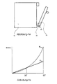
- This force increases by the voltage range of the return spring at each opening angle of the front door in a linear relationship. Due to the momentary effect caused by the weight of the door, the door has a progressive character as soon as the opening angle of the door increases and thereby approaches the x-axis. This ensures that, with the moment balanced by the spring constant, the door is compensated and locked only up to the predetermined opening angle by its weight (see moment diagram in Fig.
- the US 2,425,365 describes a domestic appliance with a frame and a chamber, wherein the chamber is closable by a front door.
- the front door is rotatably connected to the frame via a hinge part.
- an intermediate connection element is further arranged, which is further connected to a return spring.
- the opening of the front door has a rotation of the hinge part, and thus an increase in the tension of the return spring result.
- WO 2007/088141 A1 is another household appliance with a closable by a front door chamber known.
- the front door is attached to a hinge part, within which a return spring and a mechanism for tensioning the return spring when opening the front door are provided.
- a similarly constructed household appliance is in the EP 1 055 882 A2 described.
- the domestic appliance has a chamber and a front door for closing the chamber, wherein the front door is attached to a hinge part.
- a return spring and means for tensioning the spring are arranged when opening the front door.
- Purpose of the present invention is the compensation of the opening of the front door of a household appliance in a horizontal axis by means of a compensating progressive moment, which is caused by the weight of the door.
- Another purpose of this invention is to provide a progressive balancing torque without modifying a parameter from the return spring by means of an interconnecting member.
- the novelty is to provide a domestic appliance comprising a frame with a chamber, a hinge for resting on the frame of the front door closing and opening horizontally and a return spring for balancing the front door weight, a spring connection for transmitting movement between the said hinge and the return spring, an intermediate connection element with a spring connection and a hinge joint.
- the rotation surface which in the stated manner of opening the front door up to a predetermined free rotation angle in the direction of rotation of the door allows rotation of the hinge joint during opening, characterized by a stopper, which, as soon as the said hinge exceeds the free rotation angle, the hinge joint closes ,
- the cited stopper is shown in the form of an extension of the rotational surface of the hinge joint, whereby a rotational and locking function can be ensured on the joint member.
- the invention is characterized by a lever carrying at one end the hinge joint and at the other end the spring connection.
- the lever is a distance granted by the locking of the joint element, the moment will increase the spring distance.
- the rotating surface is basically a circular spring, whereby the joint element allows a rotation after the free rotation angle.
- a lever arm is characterized extending to the frame via a hinge and with which the return spring is connected to increase the pulling distance of the return spring during the door opening.
- the lever arm increases the tension of the spring by moving the front door in the direction of the door opening.
- the invention is characterized at least with a bearing on which the hinge element of the hinge is mounted, whereby the hinge element can be easily attached to the hinge.
- a joint surface is shown on the bearing, which carries the surface of revolution.
- At least one locking surface is attached to the bearing to block the extension form.
- a cylinder-type joint is deformed which deforms the spring connection, whereby the spring is e.g. reached at the tip of the hook without rotation a free rotation.
- the hinge joint is generally shown in bolt form, whereby the hinge joint includes a hinge surface and a locking surface with a lateral edge.
- FIG 1a a dishwasher is shown, at the bottom of which there is a frame (10) with a chamber (14) and with a hinge (20) in the direction x-axis (40) a hinged door (30) to be opened is mounted.
- the operator-pulled front door (30) which is fastened by means of a hinge (20), rotates and opens in the direction of the x-axis (40).
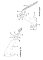
- FIG 2 the dishwasher without a side wall is shown to illustrate the mechanism of the counterbalancing device of the front door (30), wherein the front door (30) can be seen in the closed state.
- the front door (30) is fastened to the short side of the L-shaped hinge (20) from below by means of door connecting elements (22) similar to rivets.
- the long arm of the hinge (20) has a lever arm (24) and extends horizontally in the direction of the frame (10).
- the short side of the hinge hits the lever arm (24) in the corner.
- a door bearing (26) to which a x-axis (40) performing shaft is attached.
- the hinge (20) carrying the front door (30) is seated in the frame (10).
- a bearing (242) is arranged in a U-shape, wherein in the bearing (242), an intermediate connection element (50) is positioned.
- a return spring (60) with an end hinged hook (62) is mounted to the intermediate connector (50) and a frame hook (64) is attached to the rear bottom frame (10).
- a spiral body which extends over a sliding to the frame (10) inclined sliding spring (12) from below towards the front door (30).
- Figure 3a shows the intermediate connector (50) in the closed position (0 °) of the front door (30).
- the lever arm (24) extends in the direction of the frame (10). Due to the weight of the return spring (60) and the inclination of the frame (10) in the free spring length (L1), the intermediate connecting element (50) in a cylindrical joint structure at the lower tip to the spring connection (54) in the direction of frame (10) hung.
- the hinge joint (52), which connects in the form of a cam structure to the intermediate connection element (50), rests on the locking surface (244) and is at the same time set in park position, this locking surface of the bearing (242) being located near the edge of the lever arm (24). 24) is arranged.
- Figure 3b shows the intermediate connector (50) at fully open position (90 0 ) of the front door (30).
- the lever arm (24) looks up, and during the rotation in the direction of the x-axis (40), a spring is shown in the opening direction of the front door (30). Due to the return spring (60), the intermediate connection element (50) is influenced by the force of the spring connection (54) and rests with the hinge joint (52) on the locking surface (244).
- Figure 4a shows the locking surface (244) with closed front door (30) in more detail.
- Figure 4b shows the opened front door (30). In this open position one sees the lever (56), which encloses the hinge joints and the spring (52, 54) of the intermediate connection element (50) from both sides and forms a certain distance between these hinge elements.
- Figure 5a shows the intermediate connection element (50) on the longitudinal plane in cross section.
- the lever (56) is shown in a rectangular plate shape with two rounded ends and on the right side with a spring connection (54) in the form of a circular shaft.
- the spring connection (54) is circular and made of plastic with a small coefficient of friction. These characteristics allow the articulated hook (62) to rotate easily over the spring connection.
- On the left side of the lever (56) is the hinge joint (52), wherein on the side of the hinge joint (52) with the spring connection (54) in the parallel axis to the spring connection (54) a rotating surface (526) is arranged as a circular spring
- Figure 5a shows the fully opened front door (30) and the position of the bearing (242) with broken lines.
- the rotation surface (526) forms a missing spring, and during the opening and closing of the front door (30) is at a joint surface (248) which forms the bottom of the U-shaped bearing (242) , performed a limited rotational movement.
- the rotational movement is restricted by a parking stopper (524) which, with the front door (30) closed, forms the edge of the rotating surface (526) which is simultaneously positioned in the direction of the parking surface (246).
- a parking stopper (524) which, with the front door (30) closed, forms the edge of the rotating surface (526) which is simultaneously positioned in the direction of the parking surface (246).
- the rotary movement is a locking stop (522) which forms the edge of the rotating surface in the direction of the locking surface (244) and a free axis of rotation ( ⁇ ) with the parking stop (524).
- Parkstopper and locking stop (524.522) are shown circular at the junction to fix the sharpness.
- Figure 5b shows an opened front door (30) with a maximum of 30 ° defined free rotation angle and the corresponding position of the weight compensation device.
- the hinge (20) integrated with the front door (30) also rotates.
- the intermediate connector (50) has two degrees of freedom.
- the intermediate connecting element (50) moves in rotation.
- the return spring (60) fastened to the frame hook (64) is tensioned by the hook of the joint element (62) and the spring connection (54) is pulled by means of force at the level of the tension produced by the delay line and its own weight.
- the lever of the intermediate connecting element (56) extends in the direction of the return spring (60).
- the rotating surface (526) moves over the articulation surface (248), whereby the to the parking area ( 526) from its position, the front door (30) remaining closed. If the free axis of rotation is reached ( ⁇ ), the locking stop (522) is supported on the locking surface (244).
- the front door (30) is provided with a mechanism Figure 5c represented, wherein the free rotation angle ( ⁇ ) 30 0 is exceeded.
- This position shows up to a locking angle ( ⁇ ), for example 70 0 turned front door (30) relative to the frame (10).
- a locking angle ( ⁇ ) for example 70 0 turned front door (30) relative to the frame (10).
- the locking stop (522) of the intermediate connection element (50) see Fig. 5a ) on the locking surface (244).
- the hinge joint (52) will close in the rotation axis (528) against the clockwise rotation, whereby the door bearing (242) of the front door (30) to transmit the rotational movement to the lever (56) without bearing on the joint surface (248) , Subsequently, the front door (30), lever arm (24) and intermediate connecting element (50) rotate like a single component on the door bearing (26) in a horizontal axis (40).
- the return spring (60) rotates during the rotational movement within the spring connection (54) with the cylinder-like joint element and simultaneously stretches further.
Landscapes
- Closing And Opening Devices For Wings, And Checks For Wings (AREA)
Description
Die vorliegende Erfindung betrifft ein Hausgerät mit einer Ausgleichsvorrichtung, wobei an der Ausgleichsvorrichtung eine Rückholfeder angebracht ist und die angeführte Rückholfeder mit einem Verbindungselement an das Scharnier der Vordertür montiert ist, um das Gewicht der an einer waagerechten Achse des Rahmens angebrachten Vordertür auszugleichen.The present invention relates to a domestic appliance with a balancing device, wherein a return spring is mounted on the balancing device and the said return spring is mounted with a connecting element to the hinge of the front door to compensate for the weight of the front door mounted on a horizontal axis of the frame.
Die Vordertür der Innenkammer eines Rahmens im Geschirrspülgerät wird im waagerechten Drehwinkel in Richtung Boden mit Hilfe eines am oberen Bereich der Vordertür angebrachten Griffs durch Ziehen geöffnet, wobei die Tür am Bodenbereich mit gegenseitig befestigten Scharnieren befestigt wird. Durch das Gewicht der Vordertür entsteht in Öffnungsrichtung an den Scharnieren ein Moment, das ohne Gegenmaßnahmen zur ungewollten Türöffnung und infolgedessen zu Türschäden führt.The front door of the inner chamber of a frame in the dishwasher is opened in the horizontal rotation angle towards the ground by means of a handle attached to the upper part of the front door by pulling, the door being fixed to the floor area with mutually attached hinges. Due to the weight of the front door creates a moment in the opening direction of the hinges, which leads without countermeasures to unwanted door opening and consequently door damage.
Das angeführte Problem wird mittels einer Vorrichtung zum Türgewichtsausgleich gelöst. Die Vorrichtung beinhaltet eine Rückholfeder, die von einer Seite mit dem Rahmen und von der anderen Seite mittels eines Scharniers in Gegenrichtung der Öffnung einen Zug ausführend mit der Vordertür verbunden ist. Die Verbindung zwischen Rückholfeder und Scharnier erfolgt über ein Zwischenverbindungselement, das gegenüber der Rückholfeder und den Scharnieren je eine Verbindungswelle enthält, damit die Enden von Rückholfeder und Scharnier geschützt und zugleich auf einfache Weise demontiert werden können.The stated problem is solved by means of a device for door weight balance. The device includes a return spring which is connected to the frame from one side to the frame and from the other side by means of a hinge in the opposite direction of the opening, a train is connected to the front door. The connection between the return spring and the hinge via an intermediate connecting element, which contains a respective connecting shaft relative to the return spring and the hinges, so that the ends of the return spring and hinge can be protected and at the same time easily disassembled.
An beiden Enden des Zwischenverbindungselements ist an den zueinander parallel positionierten Wellen je eine Verbindungsverlängerung in Form von Haken bereitgestellt. Diese bilden je ein Verbindungslager für die gegenüberliegenden Scharniere und die Rückholfeder, wobei die Wellen zylinderartige Gelenke aufweisen.At each end of the intermediate connection element, a connection extension in the form of hooks is provided on the shafts positioned parallel to each other. These each form a connection bearing for the opposite hinges and the return spring, wherein the waves have cylinder-like joints.
Um das durch das Türgewicht gebildete Moment zu kompensieren, wird von der Rückholfeder die Vordertür mittels Scharnier in Gegenrichtung zur Türöffnung gezogen, wobei durch die Kraft der Federkonstante der Effekt des Gegenmoments erzeugt wird. Diese Kraft vergrößert sich durch die Spannungsstrecke der Rückholfeder bei jedem Öffnungswinkel der Vordertür im linearen Verhältnis. Die Tür weist durch den bedingt durch das Türgewicht entstehenden Momenteffekt einen progressiven Charakter auf, sobald sich der Öffnungswinkel der Tür vergrößert und sich dadurch der x-Achse annähert. Somit ist gewährleistet, dass mit dem durch die Federkonstante ausgeglichenen Moment die Tür nur bis zum vorgegebenen Öffnungswinkel durch ihr Gewicht ausgeglichen wird und arretiert (siehe Moment-Diagramm in
Die
Weitere Hausgeräte mit einem ähnlichen Aufbau sind aus
Aus der
Ein ähnlich aufgebautes Hausgerät ist in der
Zweck der vorliegenden Erfindung ist die Kompensierung des bei der Öffnung der Vordertür eines Hausgeräts in einer waagerechten Achse anhand einer Ausgleichsvorrichtung progressiven Moments, welches durch das Türgewicht entsteht.Purpose of the present invention is the compensation of the opening of the front door of a household appliance in a horizontal axis by means of a compensating progressive moment, which is caused by the weight of the door.
Ein weiterer Zweck dieser Erfindung ist die Gewährleistung eines progressiven Ausgleichsmoments ohne Modifizierung eines Parameters von der Rückholfeder mit Hilfe eines Zwischenverbindungselements.Another purpose of this invention is to provide a progressive balancing torque without modifying a parameter from the return spring by means of an interconnecting member.
Um die oben angeführten Ziele der vorliegenden Erfindung zu erreichen, wird durch die Neuheit ein Hausgerät erbracht, welches einen Rahmen mit Kammer, ein Scharnier zum Aufliegen auf dem Rahmen der die Kammer im waagerechten Drehwinkel schließenden und öffnenden Vordertür und eine Rückholfeder zum Ausgleich des Vordertürgewichts, eine Federverbindung zur Bewegungsübertragung zwischen dem angeführten Scharnier und der Rückholfeder, ein Zwischenverbindungselement mit einer Federverbindung und einem Scharniergelenk aufweist.In order to achieve the above-mentioned objects of the present invention, the novelty is to provide a domestic appliance comprising a frame with a chamber, a hinge for resting on the frame of the front door closing and opening horizontally and a return spring for balancing the front door weight, a spring connection for transmitting movement between the said hinge and the return spring, an intermediate connection element with a spring connection and a hinge joint.
Erfindungsgemäß ist die Drehfläche, die bei der angeführten Öffnungsweise der Vordertür bis zu einem vorgegebenen freien Drehwinkel in Drehrichtung der Tür ein Drehen des Scharniergelenks während des Öffnens gewährt, mit einem Stopper charakterisiert, der, sobald das angeführte Scharnier den freien Drehwinkel überschreitet, das Scharniergelenk schließt.According to the invention, the rotation surface, which in the stated manner of opening the front door up to a predetermined free rotation angle in the direction of rotation of the door allows rotation of the hinge joint during opening, characterized by a stopper, which, as soon as the said hinge exceeds the free rotation angle, the hinge joint closes ,
Bei manchen Ausführungen dieser Erfindung ist der angeführte Stopper in Form einer Verlängerung der Drehfläche des Scharniergelenks dargestellt, wodurch am Gelenkelement eine Dreh- und Verriegelungsfunktion gewährleistet werden kann.In some embodiments of this invention, the cited stopper is shown in the form of an extension of the rotational surface of the hinge joint, whereby a rotational and locking function can be ensured on the joint member.
Bei manchen Ausführungen ist die Erfindung mit einem Hebel charakterisiert, der an einem Ende das Scharniergelenk und an dem anderen Ende die Federverbindung trägt. Durch den Hebel wird ein Abstand gewährt und durch die Verriegelung des Gelenkelements wird das Moment die Federstrecke vergrößern.In some embodiments, the invention is characterized by a lever carrying at one end the hinge joint and at the other end the spring connection. The lever is a distance granted by the locking of the joint element, the moment will increase the spring distance.
Bei manchen Ausführungen der Erfindung ist die Drehfläche grundsätzlich eine Kreisfeder, wodurch das Gelenkelement nach dem freien Drehwinkel eine Drehung zulässt.In some embodiments of the invention, the rotating surface is basically a circular spring, whereby the joint element allows a rotation after the free rotation angle.
Bei manchen Ausführungen der Erfindung ist ein Hebelarm charakterisiert, der sich zum Rahmen hin über ein Scharnier erstreckt und mit dem die Rückholfeder verbunden ist, um die Zugstrecke der Rückholfeder während der Türöffnung zu vergrößern. Der Hebelarm vergrößert die Zugstrecke der Feder durch die Bewegung der Vordertür in Richtung Türöffnung.In some embodiments of the invention, a lever arm is characterized extending to the frame via a hinge and with which the return spring is connected to increase the pulling distance of the return spring during the door opening. The lever arm increases the tension of the spring by moving the front door in the direction of the door opening.
Bei manchen Ausführungen ist die Erfindung mindestens mit einem Lager charakterisiert, an dem das Gelenkelement des Scharniers montiert ist, wodurch das Gelenkelement einfach an das Scharnier angebracht werden kann.In some embodiments, the invention is characterized at least with a bearing on which the hinge element of the hinge is mounted, whereby the hinge element can be easily attached to the hinge.
Bei manchen Ausführungen der Erfindung ist am Lager eine Gelenkfläche dargestellt, die die Drehfläche trägt.In some embodiments of the invention, a joint surface is shown on the bearing, which carries the surface of revolution.
Bei manchen Ausführungen der Erfindung ist an dem Lager mindestens eine Verriegelungsfläche angebracht, um die Verlängerungsform zu blockieren.In some embodiments of the invention, at least one locking surface is attached to the bearing to block the extension form.
Bei manchen Ausführungen der Erfindung ist ein zylinderartiges Gelenk charakterisiert, das die Federverbindung verformt, wodurch die Feder z.B. an der Hakenspitze ohne Verdrehung eine freie Drehmöglichkeit erreicht.In some embodiments of the invention, a cylinder-type joint is deformed which deforms the spring connection, whereby the spring is e.g. reached at the tip of the hook without rotation a free rotation.
Bei manchen Ausführungen der Erfindung ist das Scharniergelenk grundsätzlich in Bolzenform dargestellt, wodurch das Scharniergelenk eine Gelenkfläche und eine Verriegelungsfläche mit einem seitlichen Rand enthält.In some embodiments of the invention, the hinge joint is generally shown in bolt form, whereby the hinge joint includes a hinge surface and a locking surface with a lateral edge.
Die weiteren Eigenschaften und Vorteile der vorliegenden Erfindung werden für die betreffenden Fachtechniker durch detaillierte Erläuterungen und Zeichnungen in den nachfolgenden Abschnitten verständlich gemacht.The other characteristics and advantages of the present invention will be understood by those skilled in the art through detailed explanations and drawings in the following paragraphs.
Die Einzelheiten und einige Vorteile der vorliegenden Erfindung werden durch die Erläuterungen und Zeichnungen ausführlich geschildert. Die Zeichnungen dienen dazu, die vorliegende Erfindung ohne irgendeine Einschränkung mittels Beispielen zu erklären.
-
Abbildung 1a -
Abbildung 1b -
Abbildung 2Abbildung 1 unten. -
Abbildung 3a -
Abbildung 3bAbbildung 3a -
Abbildung 4aAbbildung 3a -
Abbildung 4bAbbildung 3b -
Abbildung 5a -
Abbildung 5b -
Abbildung 5cAbbildung 5b
-
Figure 1a shows the perspective view of a household appliance with an attached intermediate connector. -
Figure 1b shows the state of the art of the method used the moment-angle diagram. -
Figure 2 shows the device for door opening and counterbalance without side wall in theillustration 1 below. -
Figure 3a shows the present invention with attached intermediate connection element, wherein the Rückholfeder- and hinge ratio is shown from the front. The door is closed here. -
Figure 3b shows the state of the interconnecting element ofFigure 3a from the front with the door open. -
Figure 4a shows that inFigure 3a illustrated intermediate element without spring in perspective view. -
Figure 4b shows that inFigure 3b illustrated intermediate connection element without spring in perspective view. -
Figure 5a shows the interconnecting element from the front in cross section. -
Figure 5b shows the scheme of the device for door weight balance with the door in the free rotation angle and the position of the intermediate connection element. -
Figure 5c shows the imFigure 5b illustrated mechanism with the front door in the locking angle.
Bevor die Strukturierungen der vorliegenden Erfindung ausführlich erläutert werden, ist hervorzuheben, dass die vorliegende Erfindung sich nicht mit der Ausführung von Komponenten-Arrangements und Konstruktionsdetails gemäß Beschreibungen und Definitionen in den nachfolgenden Abschnitten beschränkt.
In
In
Das Scharniergelenk (52), das sich in Form von einer Nockenstruktur an das Zwischenverbindungselement (50) verbindet, stützt sich auf die Verriegelungsfläche (244) und wird zugleich in Parkposition gestellt, wobei diese Verriegelungsfläche des Lagers (242) nahe der Kante des Hebelarms (24) angeordnet ist.
The hinge joint (52), which connects in the form of a cam structure to the intermediate connection element (50), rests on the locking surface (244) and is at the same time set in park position, this locking surface of the bearing (242) being located near the edge of the lever arm (24). 24) is arranged.
Die Drehbewegung wird durch einen Parkstopper (524) eingeschränkt, der bei geschlossener Vordertür (30) den Rand der Drehfläche (526) bildet, die gleichzeitig in Richtung Parkfläche (246) positioniert ist. Wird die Vordertür (30) vollständig geöffnet, ist die Drehbewegung ein Verriegelungsanschlag (522), der in Richtung Verriegelungsfläche (244) den Rand der Drehfläche und mit dem Parkstopper (524) eine freie Drehachse (α) bildet. Beim Scharniergelenk (52) sind an der Verbindungsstelle Parkstopper und Verriegelungsanschlag (524,522) zur Behebung der Schärfe kreisförmig dargestellt.The rotational movement is restricted by a parking stopper (524) which, with the front door (30) closed, forms the edge of the rotating surface (526) which is simultaneously positioned in the direction of the parking surface (246). When the front door (30) is fully opened, the rotary movement is a locking stop (522) which forms the edge of the rotating surface in the direction of the locking surface (244) and a free axis of rotation (α) with the parking stop (524). In the hinge joint (52) Parkstopper and locking stop (524.522) are shown circular at the junction to fix the sharpness.
Bei Spannung der Rückholfeder (60) während der Öffnung der Vordertür (30) wird bedingt durch die entstehende Zugkraft des Scharniergelenks (52) nur eine eingeschränkte Drehung ausgeführt. Aufgrund dieser Faktoren wird die Bewegung mit Einfluss auf die Gewichtausgleichsvorrichtung in
Bis zur freien Drehachse (α) wird während der Drehbewegung der Vordertür (30) aufgrund des Gewichts der Vordertür (30) das entstehende Moment in der x-Achse (40) durch das aus der Kraft des Federkoeffizienten der Rückholfeder (60) entstehende Ausgleichsmoment kompensiert. Hält das Ausgleichsmoment bei geschlossener Vordertür (30) bis zu dem freien Drehwinkel (α) zwischen einem bestimmten Winkelwert, entspricht der auf Hebelarm (24) rechtwinklig wirkende Kraftkomponentenwert zwischen Zwischenverbindungselement (50) und Hebelarm (24) dem Wert, der sich aus der Multiplikation der Hebelarmlänge (24) und einer freien Federlänge (r1) der Rückholfeder (60) ergibt.Up to the free axis of rotation (α) the resulting moment in the x-axis (40) is compensated during the rotational movement of the front door (30) due to the weight of the front door (30) by the resulting from the force of the spring coefficient of the return spring (60) compensation torque , If the balancing torque with closed front door (30) up to the free rotation angle (α) between a certain angle value, corresponds to the lever arm (24) perpendicular force component between interconnecting element (50) and lever arm (24) corresponds to the value resulting from the multiplication the lever arm length (24) and a free spring length (r1) of the return spring (60) results.
Bei einem Ausführungsbeispiel der vorliegenden Erfindung ist die Vordertür (30) mit einem Mechanismus auf
Im Verriegelungswinkel (β) vergrößert sich der normale Winkel im Verhältnis zur Bodenebene des Vordertürgewichts (30) und führt dadurch zur progressiven Vergrößerung des Moments. Andererseits ist die Struktur des Mechanismus, der das Ausgleichsmoment bildet, durch die Vergrößerung der Strecke des Hebelarms (24) wegen der Fixierung des Zwischenverbindungshebels (50) länger als der entstehende freie Hebelarm (r1). Der Momenteffekt dieser Struktur entspricht dem Wert, der sich aus der Multiplikation von Federlänge mit Verschluss (L2) des Hebalarms mit Verschluss (r2) in der neuen Position der Rückholfeder (60) ergibt, die zwischen x-Achse (40) und Federverbindung (54) gemessen wird.In the locking angle (β), the normal angle increases in relation to the ground plane of the front door weight (30) and thereby leads to the progressive increase of the moment. On the other hand, by increasing the distance of the lever arm (24) due to the fixation of the intermediate link lever (50), the structure of the mechanism constituting the balance torque is longer than the resulting free lever arm (r1). The momentary effect of this structure corresponds to the value resulting from the multiplication of spring length with closure (L2) of the lifting alarm with closure (r2) in the new position of the return spring (60) which is between x-axis (40) and spring connection (54 ) is measured.
Bei Verschließen der Vordertür (30) ist für das Gewichtsausgleichsmoment der Hebelarm mit Verschluss (r2) im Verriegelungswinkel (β) und ab dem freien Drehwinkel (α) bis zur geschlossenen Position der freie Hebelarm (r1) bestimmend.
Claims (10)
- Household appliance with a frame (10) and a compartment (14), wherein the compartment (14) is able to be closed off by a front door (30),
wherein the front door (30) is connected pivotably to the frame (10) via a hinge part (20), in order to make it possible to open the front door (30),
wherein, to compensate for the weight of the front door (30), a return spring (60) is provided,
wherein an intermediate connection element (50) is disposed between the hinge part (20) and the return spring (60) to transmit the movement
wherein a spring connection (54) is formed between the intermediate connection element (50) and the return spring (60) and a hinge joint (52) is formed between the intermediate connection element (50) and the hinge part (20),
characterised in that the hinge joint (52) comprises a rotation surface (526) and a locking stop (522), in order to make possible,
a rotational movement of the hinge part (20) in relation to the intermediate connection element (50) during a rotation of the hinge part (20) as a result of opening the front door (30) starting from a closed position of the front door (30) up to a predetermined angle of rotation (α),
and a locking of the hinge joint (52) and as a result a rotation of the intermediate connection element (50) with the hinge part (20) during a rotation of the hinge part (20), as from a continuing opening of the front door (30) and exceeding of the predetermined angle of rotation (α) up to a completely opened position of the front door (30). - Household appliance according to claim 1, characterised in that the locking stop (522) is embodied in the shape of an extension of the rotation surface (526).
- Household appliance according to one of the above claims, characterised in that the intermediate connection element (50) is embodied in the form of a lever (56), at one end of which the hinge joint (52) and at the other end of which the spring joint (54) is disposed.
- Household appliance according to one of the above claims, characterised in that the rotation surface (526) of the hinge joint (52) is embodied semicircular in shape.
- Household appliance according to one of the above claims, characterised in that the hinge part (20) has a lever arm (24) which extends through to the frame (10), wherein the lever arm (24) is linked to the return spring (60), so that when the hinge part (20) turns as the front door (30) is being opened, the distance that the return spring (60) stretches is increased.
- Household appliance according to one of the above claims, characterised in that the hinge joint (52) is formed by a support (242) provided on the hinge part (20) and by a hinge element provided on the intermediate connection element (50) and positioned in the support (242).
- Household appliance according to claim 6, characterised in that the support (242) of the hinge part (20) has a hinging surface (248) which bears the turning surface (526).
- Household appliance according to claim 6 or 7, characterised in that the support (242) of the hinge part (20) has a locking surface (244) and that the locking stop (522) is supported on the locking surface (244) when the hinge joint (52) is locked.
- Household appliance according to one of claims 6 to 8, characterised in that the hinge element provided on the intermediate connection element (50) and positioned in the support (242) takes the form of a cam.
- Household appliance according to one of the above claims, characterised in that spring connection (54) is formed by a cylinder-type hinge element provided on the intermediate connection element (50) and by a hinged hook (62) provided at one end of the return spring (60).
Priority Applications (1)
| Application Number | Priority Date | Filing Date | Title |
|---|---|---|---|
| PL09765766T PL2291105T3 (en) | 2008-06-16 | 2009-06-08 | Household appliance with device for door weight compensation |
Applications Claiming Priority (2)
| Application Number | Priority Date | Filing Date | Title |
|---|---|---|---|
| TR2008/04364A TR200804364A1 (en) | 2008-06-16 | 2008-06-16 | Household appliance with door weight compensation |
| PCT/EP2009/057021 WO2009153186A1 (en) | 2008-06-16 | 2009-06-08 | Household appliance with device for door weight compensation |
Publications (2)
| Publication Number | Publication Date |
|---|---|
| EP2291105A1 EP2291105A1 (en) | 2011-03-09 |
| EP2291105B1 true EP2291105B1 (en) | 2014-11-26 |
Family
ID=40972949
Family Applications (1)
| Application Number | Title | Priority Date | Filing Date |
|---|---|---|---|
| EP09765766.2A Active EP2291105B1 (en) | 2008-06-16 | 2009-06-08 | Household appliance with device for door weight compensation |
Country Status (5)
| Country | Link |
|---|---|
| EP (1) | EP2291105B1 (en) |
| ES (1) | ES2526416T3 (en) |
| PL (1) | PL2291105T3 (en) |
| TR (1) | TR200804364A1 (en) |
| WO (1) | WO2009153186A1 (en) |
Families Citing this family (1)
| Publication number | Priority date | Publication date | Assignee | Title |
|---|---|---|---|---|
| US9642511B2 (en) * | 2015-09-30 | 2017-05-09 | Haier Us Appliance Solutions, Inc. | In-situ door removal device in a dishwashing appliance |
Family Cites Families (5)
| Publication number | Priority date | Publication date | Assignee | Title |
|---|---|---|---|---|
| US2425365A (en) | 1945-11-13 | 1947-08-12 | Aviat Corp | Counterbalanced door structure |
| US3921252A (en) | 1974-04-29 | 1975-11-25 | Gen Electric | Hinge assembly for a dishwasher door |
| DE8709496U1 (en) | 1987-07-10 | 1987-08-20 | Miele & Cie Gmbh & Co, 4830 Guetersloh, De | |
| DE19923994A1 (en) | 1999-05-26 | 2000-11-30 | Bsh Bosch Siemens Hausgeraete | Household appliance hinge device |
| ITPD20060034A1 (en) | 2006-02-02 | 2007-08-03 | Zanovello Srl | HINGE FOR OVEN OR SIMILAR DOORS |
-
2008
- 2008-06-16 TR TR2008/04364A patent/TR200804364A1/en unknown
-
2009
- 2009-06-08 WO PCT/EP2009/057021 patent/WO2009153186A1/en active Application Filing
- 2009-06-08 PL PL09765766T patent/PL2291105T3/en unknown
- 2009-06-08 EP EP09765766.2A patent/EP2291105B1/en active Active
- 2009-06-08 ES ES09765766.2T patent/ES2526416T3/en active Active
Also Published As
| Publication number | Publication date |
|---|---|
| WO2009153186A1 (en) | 2009-12-23 |
| ES2526416T3 (en) | 2015-01-12 |
| PL2291105T3 (en) | 2015-04-30 |
| TR200804364A1 (en) | 2011-07-21 |
| EP2291105A1 (en) | 2011-03-09 |
Similar Documents
| Publication | Publication Date | Title |
|---|---|---|
| DE102008025265B4 (en) | folding cover | |
| DE102008026383A1 (en) | Domestic appliance with a door having a braking device | |
| EP2238306A1 (en) | Holding element for adjusting a cover of a piece of furniture | |
| EP3556976A1 (en) | Device for moving a piece of furniture on a body of a piece of furniture | |
| WO2019091969A1 (en) | Wing fitting for a piece of furniture, side wall of a body of a piece of furniture and piece of furniture comprising a side wall | |
| DE102007053093A1 (en) | Household appliance with door weight balance device | |
| DE102006044873A1 (en) | Furniture or built-in unit for building into furniture has upper and lower levers connecting upper and lower swivel bearings respectively and connected by connecting lever | |
| EP2291105B1 (en) | Household appliance with device for door weight compensation | |
| DE4418238A1 (en) | Multi=link hinge for refrigerator door | |
| WO2008034652A1 (en) | Motorized drive | |
| EP2998496B1 (en) | Hinge, in particular for the lid of a household appliance | |
| EP2274492A1 (en) | Household appliance | |
| DE102018100672A1 (en) | Furniture hinge, furniture panel and furniture body | |
| EP2142736B1 (en) | Fitting for a window, door or similar | |
| EP2341293B1 (en) | Domestic appliance with fixing device | |
| EP3326491A1 (en) | Fitting for the mobile positioning of a shelf board in a corner cupboard by means of a cogged wheel | |
| DE2720102C2 (en) | Counterbalanced door hinge for household appliances | |
| DE202010014477U1 (en) | fitting assembly | |
| DE4443098A1 (en) | Electric appliance door mechanism | |
| DE19548512A1 (en) | Hinge for drop-down door of domestic electrical appliance esp. dishwasher | |
| DE102007001927B3 (en) | Plastic window or door, has corner bearing with counter bearing having counter bearing base provided with counter bearing projection, where base is supported at fixed frame opposite side against misalignment by opening side at fixed frame | |
| DE102015102387A1 (en) | Sliding tilt mechanism of a storage of a household appliance and household appliance | |
| DE60203732T2 (en) | COUNTERWEIGHT HINGE DEVICE WITH VERTICAL MOTION FOR ONE DOOR | |
| EP2369111B1 (en) | Corner bearing for concealed assembly | |
| DE102021113124B3 (en) | Hinge with safety element |
Legal Events
| Date | Code | Title | Description |
|---|---|---|---|
| PUAI | Public reference made under article 153(3) epc to a published international application that has entered the european phase |
Free format text: ORIGINAL CODE: 0009012 |
|
| 17P | Request for examination filed |
Effective date: 20110117 |
|
| AK | Designated contracting states |
Kind code of ref document: A1 Designated state(s): AT BE BG CH CY CZ DE DK EE ES FI FR GB GR HR HU IE IS IT LI LT LU LV MC MK MT NL NO PL PT RO SE SI SK TR |
|
| AX | Request for extension of the european patent |
Extension state: AL BA RS |
|
| RIN1 | Information on inventor provided before grant (corrected) |
Inventor name: BAMBAL, SEBAHATTIN Inventor name: AYBAS, MUTLU YUCEL Inventor name: SIMSEK, OEVUENC |
|
| DAX | Request for extension of the european patent (deleted) | ||
| GRAP | Despatch of communication of intention to grant a patent |
Free format text: ORIGINAL CODE: EPIDOSNIGR1 |
|
| INTG | Intention to grant announced |
Effective date: 20140903 |
|
| GRAS | Grant fee paid |
Free format text: ORIGINAL CODE: EPIDOSNIGR3 |
|
| GRAA | (expected) grant |
Free format text: ORIGINAL CODE: 0009210 |
|
| AK | Designated contracting states |
Kind code of ref document: B1 Designated state(s): AT BE BG CH CY CZ DE DK EE ES FI FR GB GR HR HU IE IS IT LI LT LU LV MC MK MT NL NO PL PT RO SE SI SK TR |
|
| REG | Reference to a national code |
Ref country code: GB Ref legal event code: FG4D Free format text: NOT ENGLISH |
|
| REG | Reference to a national code |
Ref country code: CH Ref legal event code: EP |
|
| REG | Reference to a national code |
Ref country code: AT Ref legal event code: REF Ref document number: 697702 Country of ref document: AT Kind code of ref document: T Effective date: 20141215 |
|
| REG | Reference to a national code |
Ref country code: IE Ref legal event code: FG4D Free format text: LANGUAGE OF EP DOCUMENT: GERMAN |
|
| REG | Reference to a national code |
Ref country code: DE Ref legal event code: R096 Ref document number: 502009010275 Country of ref document: DE Effective date: 20141231 |
|
| REG | Reference to a national code |
Ref country code: ES Ref legal event code: FG2A Ref document number: 2526416 Country of ref document: ES Kind code of ref document: T3 Effective date: 20150112 |
|
| REG | Reference to a national code |
Ref country code: CH Ref legal event code: PFA Owner name: BSH HAUSGERAETE GMBH, DE Free format text: FORMER OWNER: BSH BOSCH UND SIEMENS HAUSGERAETE GMBH, DE |
|
| RAP2 | Party data changed (patent owner data changed or rights of a patent transferred) |
Owner name: BSH HAUSGERAETE GMBH |
|
| REG | Reference to a national code |
Ref country code: NL Ref legal event code: VDEP Effective date: 20141126 |
|
| REG | Reference to a national code |
Ref country code: LT Ref legal event code: MG4D |
|
| PG25 | Lapsed in a contracting state [announced via postgrant information from national office to epo] |
Ref country code: NO Free format text: LAPSE BECAUSE OF FAILURE TO SUBMIT A TRANSLATION OF THE DESCRIPTION OR TO PAY THE FEE WITHIN THE PRESCRIBED TIME-LIMIT Effective date: 20150226 Ref country code: FI Free format text: LAPSE BECAUSE OF FAILURE TO SUBMIT A TRANSLATION OF THE DESCRIPTION OR TO PAY THE FEE WITHIN THE PRESCRIBED TIME-LIMIT Effective date: 20141126 Ref country code: NL Free format text: LAPSE BECAUSE OF FAILURE TO SUBMIT A TRANSLATION OF THE DESCRIPTION OR TO PAY THE FEE WITHIN THE PRESCRIBED TIME-LIMIT Effective date: 20141126 Ref country code: LT Free format text: LAPSE BECAUSE OF FAILURE TO SUBMIT A TRANSLATION OF THE DESCRIPTION OR TO PAY THE FEE WITHIN THE PRESCRIBED TIME-LIMIT Effective date: 20141126 Ref country code: PT Free format text: LAPSE BECAUSE OF FAILURE TO SUBMIT A TRANSLATION OF THE DESCRIPTION OR TO PAY THE FEE WITHIN THE PRESCRIBED TIME-LIMIT Effective date: 20150326 Ref country code: IS Free format text: LAPSE BECAUSE OF FAILURE TO SUBMIT A TRANSLATION OF THE DESCRIPTION OR TO PAY THE FEE WITHIN THE PRESCRIBED TIME-LIMIT Effective date: 20150326 |
|
| REG | Reference to a national code |
Ref country code: PL Ref legal event code: T3 |
|
| REG | Reference to a national code |
Ref country code: DE Ref legal event code: R081 Ref document number: 502009010275 Country of ref document: DE Owner name: BSH HAUSGERAETE GMBH, DE Free format text: FORMER OWNER: BSH BOSCH UND SIEMENS HAUSGERAETE GMBH, 81739 MUENCHEN, DE Effective date: 20150407 |
|
| PG25 | Lapsed in a contracting state [announced via postgrant information from national office to epo] |
Ref country code: CY Free format text: LAPSE BECAUSE OF FAILURE TO SUBMIT A TRANSLATION OF THE DESCRIPTION OR TO PAY THE FEE WITHIN THE PRESCRIBED TIME-LIMIT Effective date: 20141126 Ref country code: LV Free format text: LAPSE BECAUSE OF FAILURE TO SUBMIT A TRANSLATION OF THE DESCRIPTION OR TO PAY THE FEE WITHIN THE PRESCRIBED TIME-LIMIT Effective date: 20141126 Ref country code: SE Free format text: LAPSE BECAUSE OF FAILURE TO SUBMIT A TRANSLATION OF THE DESCRIPTION OR TO PAY THE FEE WITHIN THE PRESCRIBED TIME-LIMIT Effective date: 20141126 Ref country code: GR Free format text: LAPSE BECAUSE OF FAILURE TO SUBMIT A TRANSLATION OF THE DESCRIPTION OR TO PAY THE FEE WITHIN THE PRESCRIBED TIME-LIMIT Effective date: 20150227 Ref country code: HR Free format text: LAPSE BECAUSE OF FAILURE TO SUBMIT A TRANSLATION OF THE DESCRIPTION OR TO PAY THE FEE WITHIN THE PRESCRIBED TIME-LIMIT Effective date: 20141126 |
|
| REG | Reference to a national code |
Ref country code: ES Ref legal event code: PC2A Owner name: BSH HAUSGERATE GMBH Effective date: 20150529 |
|
| REG | Reference to a national code |
Ref country code: FR Ref legal event code: PLFP Year of fee payment: 7 |
|
| PG25 | Lapsed in a contracting state [announced via postgrant information from national office to epo] |
Ref country code: RO Free format text: LAPSE BECAUSE OF FAILURE TO SUBMIT A TRANSLATION OF THE DESCRIPTION OR TO PAY THE FEE WITHIN THE PRESCRIBED TIME-LIMIT Effective date: 20141126 Ref country code: DK Free format text: LAPSE BECAUSE OF FAILURE TO SUBMIT A TRANSLATION OF THE DESCRIPTION OR TO PAY THE FEE WITHIN THE PRESCRIBED TIME-LIMIT Effective date: 20141126 Ref country code: CZ Free format text: LAPSE BECAUSE OF FAILURE TO SUBMIT A TRANSLATION OF THE DESCRIPTION OR TO PAY THE FEE WITHIN THE PRESCRIBED TIME-LIMIT Effective date: 20141126 Ref country code: SK Free format text: LAPSE BECAUSE OF FAILURE TO SUBMIT A TRANSLATION OF THE DESCRIPTION OR TO PAY THE FEE WITHIN THE PRESCRIBED TIME-LIMIT Effective date: 20141126 Ref country code: EE Free format text: LAPSE BECAUSE OF FAILURE TO SUBMIT A TRANSLATION OF THE DESCRIPTION OR TO PAY THE FEE WITHIN THE PRESCRIBED TIME-LIMIT Effective date: 20141126 |
|
| REG | Reference to a national code |
Ref country code: DE Ref legal event code: R097 Ref document number: 502009010275 Country of ref document: DE |
|
| PLBE | No opposition filed within time limit |
Free format text: ORIGINAL CODE: 0009261 |
|
| STAA | Information on the status of an ep patent application or granted ep patent |
Free format text: STATUS: NO OPPOSITION FILED WITHIN TIME LIMIT |
|
| 26N | No opposition filed |
Effective date: 20150827 |
|
| REG | Reference to a national code |
Ref country code: FR Ref legal event code: CD Owner name: BSH HAUSGERATE GMBH, DE Effective date: 20151022 |
|
| PG25 | Lapsed in a contracting state [announced via postgrant information from national office to epo] |
Ref country code: MC Free format text: LAPSE BECAUSE OF FAILURE TO SUBMIT A TRANSLATION OF THE DESCRIPTION OR TO PAY THE FEE WITHIN THE PRESCRIBED TIME-LIMIT Effective date: 20141126 |
|
| REG | Reference to a national code |
Ref country code: CH Ref legal event code: PL |
|
| GBPC | Gb: european patent ceased through non-payment of renewal fee |
Effective date: 20150608 |
|
| PG25 | Lapsed in a contracting state [announced via postgrant information from national office to epo] |
Ref country code: SI Free format text: LAPSE BECAUSE OF FAILURE TO SUBMIT A TRANSLATION OF THE DESCRIPTION OR TO PAY THE FEE WITHIN THE PRESCRIBED TIME-LIMIT Effective date: 20141126 Ref country code: LU Free format text: LAPSE BECAUSE OF FAILURE TO SUBMIT A TRANSLATION OF THE DESCRIPTION OR TO PAY THE FEE WITHIN THE PRESCRIBED TIME-LIMIT Effective date: 20150608 |
|
| REG | Reference to a national code |
Ref country code: IE Ref legal event code: MM4A |
|
| PG25 | Lapsed in a contracting state [announced via postgrant information from national office to epo] |
Ref country code: GB Free format text: LAPSE BECAUSE OF NON-PAYMENT OF DUE FEES Effective date: 20150608 Ref country code: CH Free format text: LAPSE BECAUSE OF NON-PAYMENT OF DUE FEES Effective date: 20150630 Ref country code: IE Free format text: LAPSE BECAUSE OF NON-PAYMENT OF DUE FEES Effective date: 20150608 Ref country code: LI Free format text: LAPSE BECAUSE OF NON-PAYMENT OF DUE FEES Effective date: 20150630 |
|
| REG | Reference to a national code |
Ref country code: FR Ref legal event code: PLFP Year of fee payment: 8 |
|
| REG | Reference to a national code |
Ref country code: AT Ref legal event code: MM01 Ref document number: 697702 Country of ref document: AT Kind code of ref document: T Effective date: 20150608 |
|
| PG25 | Lapsed in a contracting state [announced via postgrant information from national office to epo] |
Ref country code: AT Free format text: LAPSE BECAUSE OF NON-PAYMENT OF DUE FEES Effective date: 20150608 |
|
| PG25 | Lapsed in a contracting state [announced via postgrant information from national office to epo] |
Ref country code: MT Free format text: LAPSE BECAUSE OF FAILURE TO SUBMIT A TRANSLATION OF THE DESCRIPTION OR TO PAY THE FEE WITHIN THE PRESCRIBED TIME-LIMIT Effective date: 20141126 |
|
| PG25 | Lapsed in a contracting state [announced via postgrant information from national office to epo] |
Ref country code: HU Free format text: LAPSE BECAUSE OF FAILURE TO SUBMIT A TRANSLATION OF THE DESCRIPTION OR TO PAY THE FEE WITHIN THE PRESCRIBED TIME-LIMIT; INVALID AB INITIO Effective date: 20090608 Ref country code: BG Free format text: LAPSE BECAUSE OF FAILURE TO SUBMIT A TRANSLATION OF THE DESCRIPTION OR TO PAY THE FEE WITHIN THE PRESCRIBED TIME-LIMIT Effective date: 20141126 |
|
| REG | Reference to a national code |
Ref country code: FR Ref legal event code: PLFP Year of fee payment: 9 |
|
| PG25 | Lapsed in a contracting state [announced via postgrant information from national office to epo] |
Ref country code: BE Free format text: LAPSE BECAUSE OF NON-PAYMENT OF DUE FEES Effective date: 20150630 |
|
| REG | Reference to a national code |
Ref country code: FR Ref legal event code: PLFP Year of fee payment: 10 |
|
| PG25 | Lapsed in a contracting state [announced via postgrant information from national office to epo] |
Ref country code: MK Free format text: LAPSE BECAUSE OF FAILURE TO SUBMIT A TRANSLATION OF THE DESCRIPTION OR TO PAY THE FEE WITHIN THE PRESCRIBED TIME-LIMIT Effective date: 20141126 |
|
| PGFP | Annual fee paid to national office [announced via postgrant information from national office to epo] |
Ref country code: FR Payment date: 20220621 Year of fee payment: 14 |
|
| PGFP | Annual fee paid to national office [announced via postgrant information from national office to epo] |
Ref country code: IT Payment date: 20220630 Year of fee payment: 14 Ref country code: ES Payment date: 20220719 Year of fee payment: 14 |
|
| PGFP | Annual fee paid to national office [announced via postgrant information from national office to epo] |
Ref country code: DE Payment date: 20230630 Year of fee payment: 15 |
|
| PGFP | Annual fee paid to national office [announced via postgrant information from national office to epo] |
Ref country code: TR Payment date: 20230602 Year of fee payment: 15 Ref country code: PL Payment date: 20230531 Year of fee payment: 15 |