EP2290732A1 - Secondary battery with insulating member - Google Patents
Secondary battery with insulating member Download PDFInfo
- Publication number
- EP2290732A1 EP2290732A1 EP10169597A EP10169597A EP2290732A1 EP 2290732 A1 EP2290732 A1 EP 2290732A1 EP 10169597 A EP10169597 A EP 10169597A EP 10169597 A EP10169597 A EP 10169597A EP 2290732 A1 EP2290732 A1 EP 2290732A1
- Authority
- EP
- European Patent Office
- Prior art keywords
- electrode assembly
- rechargeable battery
- case
- battery according
- insulating member
- Prior art date
- Legal status (The legal status is an assumption and is not a legal conclusion. Google has not performed a legal analysis and makes no representation as to the accuracy of the status listed.)
- Granted
Links
- 230000003139 buffering effect Effects 0.000 claims description 8
- -1 poly propylene Polymers 0.000 claims description 6
- 239000004698 Polyethylene Substances 0.000 claims description 4
- 239000004743 Polypropylene Substances 0.000 claims description 4
- 229920001343 polytetrafluoroethylene Polymers 0.000 claims description 4
- 239000004810 polytetrafluoroethylene Substances 0.000 claims description 4
- 239000002033 PVDF binder Substances 0.000 claims description 3
- 229920001774 Perfluoroether Polymers 0.000 claims description 3
- HQQADJVZYDDRJT-UHFFFAOYSA-N ethene;prop-1-ene Chemical group C=C.CC=C HQQADJVZYDDRJT-UHFFFAOYSA-N 0.000 claims description 3
- CTYRPMDGLDAWRQ-UHFFFAOYSA-N phenyl hydrogen sulfate Chemical compound OS(=O)(=O)OC1=CC=CC=C1 CTYRPMDGLDAWRQ-UHFFFAOYSA-N 0.000 claims description 3
- 229920000573 polyethylene Polymers 0.000 claims description 3
- 229920006389 polyphenyl polymer Polymers 0.000 claims description 3
- 229920001155 polypropylene Polymers 0.000 claims description 3
- 229940058401 polytetrafluoroethylene Drugs 0.000 claims description 3
- KKEYFWRCBNTPAC-UHFFFAOYSA-L terephthalate(2-) Chemical compound [O-]C(=O)C1=CC=C(C([O-])=O)C=C1 KKEYFWRCBNTPAC-UHFFFAOYSA-L 0.000 claims description 3
- 239000004812 Fluorinated ethylene propylene Substances 0.000 claims description 2
- 229920009441 perflouroethylene propylene Polymers 0.000 claims description 2
- 229920002981 polyvinylidene fluoride Polymers 0.000 claims description 2
- 238000007789 sealing Methods 0.000 abstract description 2
- 230000014759 maintenance of location Effects 0.000 description 5
- 230000000052 comparative effect Effects 0.000 description 3
- 230000003247 decreasing effect Effects 0.000 description 3
- 238000009413 insulation Methods 0.000 description 3
- 238000010030 laminating Methods 0.000 description 3
- 239000011149 active material Substances 0.000 description 2
- 230000015556 catabolic process Effects 0.000 description 2
- 238000006731 degradation reaction Methods 0.000 description 2
- 229910052751 metal Inorganic materials 0.000 description 2
- 239000002184 metal Substances 0.000 description 2
- 229910000838 Al alloy Inorganic materials 0.000 description 1
- 229910000831 Steel Inorganic materials 0.000 description 1
- 229910052782 aluminium Inorganic materials 0.000 description 1
- XAGFODPZIPBFFR-UHFFFAOYSA-N aluminium Chemical compound [Al] XAGFODPZIPBFFR-UHFFFAOYSA-N 0.000 description 1
- 230000000712 assembly Effects 0.000 description 1
- 238000000429 assembly Methods 0.000 description 1
- 230000008602 contraction Effects 0.000 description 1
- 230000002542 deteriorative effect Effects 0.000 description 1
- 238000004880 explosion Methods 0.000 description 1
- 239000011888 foil Substances 0.000 description 1
- 238000011900 installation process Methods 0.000 description 1
- 239000012212 insulator Substances 0.000 description 1
- 238000003475 lamination Methods 0.000 description 1
- 238000012986 modification Methods 0.000 description 1
- 230000004048 modification Effects 0.000 description 1
- 239000011255 nonaqueous electrolyte Substances 0.000 description 1
- 239000010959 steel Substances 0.000 description 1
- 238000004804 winding Methods 0.000 description 1
Images


Classifications
-
- H—ELECTRICITY
- H01—ELECTRIC ELEMENTS
- H01M—PROCESSES OR MEANS, e.g. BATTERIES, FOR THE DIRECT CONVERSION OF CHEMICAL ENERGY INTO ELECTRICAL ENERGY
- H01M50/00—Constructional details or processes of manufacture of the non-active parts of electrochemical cells other than fuel cells, e.g. hybrid cells
- H01M50/10—Primary casings, jackets or wrappings of a single cell or a single battery
- H01M50/102—Primary casings, jackets or wrappings of a single cell or a single battery characterised by their shape or physical structure
- H01M50/103—Primary casings, jackets or wrappings of a single cell or a single battery characterised by their shape or physical structure prismatic or rectangular
-
- H—ELECTRICITY
- H01—ELECTRIC ELEMENTS
- H01M—PROCESSES OR MEANS, e.g. BATTERIES, FOR THE DIRECT CONVERSION OF CHEMICAL ENERGY INTO ELECTRICAL ENERGY
- H01M10/00—Secondary cells; Manufacture thereof
- H01M10/02—Details
-
- H—ELECTRICITY
- H01—ELECTRIC ELEMENTS
- H01M—PROCESSES OR MEANS, e.g. BATTERIES, FOR THE DIRECT CONVERSION OF CHEMICAL ENERGY INTO ELECTRICAL ENERGY
- H01M10/00—Secondary cells; Manufacture thereof
- H01M10/04—Construction or manufacture in general
- H01M10/0431—Cells with wound or folded electrodes
-
- H—ELECTRICITY
- H01—ELECTRIC ELEMENTS
- H01M—PROCESSES OR MEANS, e.g. BATTERIES, FOR THE DIRECT CONVERSION OF CHEMICAL ENERGY INTO ELECTRICAL ENERGY
- H01M50/00—Constructional details or processes of manufacture of the non-active parts of electrochemical cells other than fuel cells, e.g. hybrid cells
- H01M50/10—Primary casings, jackets or wrappings of a single cell or a single battery
- H01M50/147—Lids or covers
-
- H—ELECTRICITY
- H01—ELECTRIC ELEMENTS
- H01M—PROCESSES OR MEANS, e.g. BATTERIES, FOR THE DIRECT CONVERSION OF CHEMICAL ENERGY INTO ELECTRICAL ENERGY
- H01M50/00—Constructional details or processes of manufacture of the non-active parts of electrochemical cells other than fuel cells, e.g. hybrid cells
- H01M50/50—Current conducting connections for cells or batteries
- H01M50/543—Terminals
-
- H—ELECTRICITY
- H01—ELECTRIC ELEMENTS
- H01M—PROCESSES OR MEANS, e.g. BATTERIES, FOR THE DIRECT CONVERSION OF CHEMICAL ENERGY INTO ELECTRICAL ENERGY
- H01M50/00—Constructional details or processes of manufacture of the non-active parts of electrochemical cells other than fuel cells, e.g. hybrid cells
- H01M50/50—Current conducting connections for cells or batteries
- H01M50/572—Means for preventing undesired use or discharge
-
- Y—GENERAL TAGGING OF NEW TECHNOLOGICAL DEVELOPMENTS; GENERAL TAGGING OF CROSS-SECTIONAL TECHNOLOGIES SPANNING OVER SEVERAL SECTIONS OF THE IPC; TECHNICAL SUBJECTS COVERED BY FORMER USPC CROSS-REFERENCE ART COLLECTIONS [XRACs] AND DIGESTS
- Y02—TECHNOLOGIES OR APPLICATIONS FOR MITIGATION OR ADAPTATION AGAINST CLIMATE CHANGE
- Y02E—REDUCTION OF GREENHOUSE GAS [GHG] EMISSIONS, RELATED TO ENERGY GENERATION, TRANSMISSION OR DISTRIBUTION
- Y02E60/00—Enabling technologies; Technologies with a potential or indirect contribution to GHG emissions mitigation
- Y02E60/10—Energy storage using batteries
-
- Y—GENERAL TAGGING OF NEW TECHNOLOGICAL DEVELOPMENTS; GENERAL TAGGING OF CROSS-SECTIONAL TECHNOLOGIES SPANNING OVER SEVERAL SECTIONS OF THE IPC; TECHNICAL SUBJECTS COVERED BY FORMER USPC CROSS-REFERENCE ART COLLECTIONS [XRACs] AND DIGESTS
- Y02—TECHNOLOGIES OR APPLICATIONS FOR MITIGATION OR ADAPTATION AGAINST CLIMATE CHANGE
- Y02P—CLIMATE CHANGE MITIGATION TECHNOLOGIES IN THE PRODUCTION OR PROCESSING OF GOODS
- Y02P70/00—Climate change mitigation technologies in the production process for final industrial or consumer products
- Y02P70/50—Manufacturing or production processes characterised by the final manufactured product
Definitions
- This disclosure relates to a rechargeable battery. More particularly, this disclosure relates to a rechargeable battery including an insulating member having an improved structure between an electrode assembly and a case.
- a rechargeable battery can be recharged and discharged, unlike a primary battery that cannot be recharged.
- a rechargeable battery with low capacity is used for a small portable electronic device such as a mobile phone, a laptop computer, and a camcorder, while a rechargeable battery with large capacity is used as a power source for driving a motor such as for a hybrid vehicle.
- a rechargeable battery large has been developed to have large capacity, high power, and high energy density using a non-aqueous electrolyte. It can be used to drive a device, for example, a motor such as an electric vehicle requiring a large amount of electric power.
- a rechargeable battery with high power is generally formed with a plurality of rechargeable batteries coupled in series or in parallel.
- This rechargeable battery may be cylindrical or prismatic.
- a prismatic rechargeable battery includes an electrode assembly including positive and negative electrodes and a separator therebetween, a case having a space for housing it, a cap plate closing and sealing the case and having a terminal hole through which a terminal is inserted, and a terminal inserted into the case and protruded outside of the case.
- the electrode assembly needs to be insulated from the case. However, it is difficult to install an insulating film between the electrode assembly and the case. In addition, the insulation film may be torn apart during the installation process. When torn apart, it may cause an internal short cut, resulting in more critical problems such as explosion of a rechargeable battery and the like.
- the electrode assembly is prepared by laminating positive and negative electrodes and a separator therebetween and then, spiral-winding them together, and pressing them into a flat jelly-roll. Accordingly, it has a dumbbell-shaped cross-section with both edges convex.
- the flat part of the electrode assembly is relatively thinner than convex parts at the edges, it may not be stably attached to the interface of a supporting part.
- the electrode assembly therein is also repetitively expanded and shrunk.
- the electrode assembly irregularly repeats expansion and contraction, it may deteriorate performance of the rechargeable battery.
- the electrode assemblies may have a gap during the expansion.
- the gap may cause interfaces not to be uniform, resultantly deteriorating performance of a rechargeable battery.
- An exemplary embodiment of the present invention provides a rechargeable battery stably insulating an electrode assembly from a case but still maintaining the shape of the electrode assembly in order to solve the aforementioned problem.
- a rechargeable battery comprising an electrode assembly having a first electrode, a second electrode, and a separator interposed between the first and the second electrodes. Further, a case for mounting the electrode assembly therein and an insulating member being disposed between side walls of the case and the electrode assembly to insulate the case from the electrode assembly are provided.
- An exploded-top view of the insulating member has the form of a cross. In other words, in an unfolded state, the insulating member is provided to have the form of a cross.
- a rechargeable battery including an insulating member between an electrode assembly and a case in order to stably insulate the electrode assembly from the case as well as uniformly maintain the interface of the electrode assembly and thereby, stably maintain capacity.
- the first electrode and the second electrode with the separator in-between are preferably wound into a jelly-roll.
- the insulating member when folded, matches the shape of the case.
- the shape of the surface of the insulating member being in contact with the electrode assembly is preferably designed to correspond to the outer shape of the electrode assembly.
- the insulating member forces the retention of the shape of an electrode assembly between the electrode assembly and a case.
- the insulating member preferably comprises a base in contact with the bottom of the case, a first insulating plate, a second insulating plate, a third insulating plate, and a fourth insulating plate, wherein all four insulating plates are attached to the base and are arranged to face the four side surfaces of the electrode assembly, respectively.
- the wound electrode assembly preferably comprises flat parts in its middle region and convex parts in its lower and upper parts, wherein the surfaces of the first and second insulating plates being in contact with the electrode assembly are formed such that their shape corresponds to the shape of the surface of the electrode assembly having flat and convex parts.
- the first insulating plate comprises a first supporting part and the second insulating plate comprises a second supporting part, wherein the supporting parts are flat where they contact the respective flat part of the electrode assembly, and slanted or curved in the region of the respective convex part of the electrode assembly to correspond to the shape of the electrode assembly.
- the supporting part is preferably closely attached to the flat part of the electrode assembly and supports the electrode assembly.
- the supporting part is shaped to have a buffering groove adapted to allow expansion of the battery; and/or is flat in the region where it contacts the flat part of the electrode assembly.
- the supporting part may be tilted or curbed in an arc shape where it contacts the convex part of the electrode assembly; and/or may have a trapezoid-shaped cross-section.
- the buffering grooves advantageously help to stably support the electrode assembly and prevent its degradation.
- the supporting parts are designed to stably support the flat parts and also stably support the convex parts.
- the electrode assembly therein is repetitively expanded and shrunk. Then, the supporting parts press the flat part of the electrode assembly between the case and the electrode assembly, maintaining the shape of the electrode assembly and preventing the interface from not being uniform.
- the inventive rechargeable battery exhibits improved capacity retention than a battery without support parts.
- the supporting parts may comprise film sheets laminated together.
- the film sheets further improve the capacity retention of the battery.
- the insulating member is preferably formed of one selected from the group consisting of poly propylene, poly ethylene, poly phenyl sulfate, poly buthylene terephthalate, poly tetrafluoro ethylene, perfluoroalkoxy, fluorinated ethylene propylene), poly vinylidene fluoride.
- the insulating member may have the form of a cuboid with the top open.
- the insulating member in one embodiment comprises a groove on the boundary between the base and the insulating plates, the groove being provided on the top of the surface of the base facing the electrode assembly or on the bottom of the surface of the base facing the case.
- the groove may have a triangular cross-section. It may also have a quadrangular cross-section.
- the third insulating plate and the fourth insulating plate are preferably of planar shape.
- the battery preferably further comprises a first terminal and a second terminal, the first terminal being connected to the first electrode via a first lead tab, the second terminal being connected to the second electrode via a second lead tab, wherein the third insulating plate is preferably disposed between the first lead tab and the case and the fourth insulating plate is preferably disposed between the second lead tab and the case.
- the lead tabs are prevented from contacting the case.
- the base may have a quadrangular shape.
- the base may be provided with an arc-shaped top surface in the region of contact with the bottom of the electrode assembly. It may be closely attached to the bottom of the case.
- the base formed accordingly can stably support the electrode assembly having corresponding shapes.
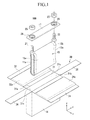
- FIG. 1 is an exploded perspective view of a rechargeable battery according to one exemplary embodiment.
- the rechargeable battery 100 includes an electrode assembly 15 including a positive electrode 11 and a negative electrode 12 and a separator 13 disposed therebetween, a case 14 having a space for housing it, a cap plate 17 combined with an opening 14a of the case 14, and a positive terminal 21 and a negative terminal 22 mounted on the cap plate 17 and electrically connected to the electrode assembly 15.
- the positive electrode 11 and the negative electrode 12 include a coated region coated with an active material on a current collector made of a thin metal foil plate and uncoated regions 11 a and 12a not coated with the active material.
- the positive uncoated region 11a is formed at one end of the positive electrode 11 along the length direction.
- the negative uncoated region 12a is formed at the other end of the negative electrode 12 along the length direction.
- the positive electrode 11 and the negative electrode 12 are laminated with a separator 13 as an insulator in the middle and then, spiral-wound into a jelly-roll, preparing an electrode assembly 15.
- the electrode assembly 15 is pressed to be flat with a press and the like, so that it can be housed in the case 14.
- the pressed assembly 15 is pushed toward both edges and expands to be convex there, forming a convex part 15b.
- a flat part 15a is formed between the both convex parts 15b.
- FIG. 2 is a perspective view of a rechargeable battery according to a first embodiment
- FIG. 3 is a cross-sectional view taken along the III-III line of FIG. 2
- FIG. 4 is a cross-sectional view taken along the IV-IV line of FIG. 2 .
- the lead tab 21 a of a positive terminal 21 at one edge of an electrode assembly is welded onto a positive uncoated region 11a.
- the lead tab 22a of a negative terminal 22 is welded onto a negative uncoated region 12a.
- the case 14 is made of a conductive metal such as aluminum, aluminum alloy, nickel-plated steel, or the like and formed as a hexahedron prism having a space for housing the electrode assembly 15 and an opening 14a at one side.
- an insulating member 30 is disposed for electric insulation between the case 14 and the electrode assembly 15.
- the insulating member 30 has a cross shape and includes a base 31 closely attached to the bottom of a case 14, a first insulating plate 32 extending from the first edge of the base 31, and a second insulating plate 34 extending from the second edge of the base 31.
- the insulating member 30 includes a third plate 36 extending from a third end 31 c crossing with the first end 31 a and a fourth insulating plate 38 extending from a fourth end 31 d facing the third end 31 c.
- the insulating member 30 may include one selected from the group consisting of PP(Poly Propylene), PE(poly ethylene), PPS(poly phenyl sulfate), PBT(Poly Buthylene Terephthalate), PTFE(Poly tetrafluoro ethylene), PFA(Perfluoroalkoxy), FEP(Fluorinated Ethylene Propylene), PVDF(Poly vinylidene fluoride).
- This insulating member 30, as shown in FIG. 1 is positioned on the opening 14a of a first case 14. It is inserted into the case 14 together with the electrode assembly 15, wherein the insulating plates 32, 34, 36, and 38 are folded together when the electrode assembly 15 is inserted into the case 14.
- the insulating member 30 is at large mounted as an exploded cuboid with the top open. Accordingly, its first shape is a cross.
- the third insulating plate 36, the base 31, and the fourth insulating plate 38 form one axis of the cross
- the first insulating plate 32, the base 31, and the second insulating plate 34 form the second, perpendicular part of the cross.
- the central crossing portion of the cross is established by the base 31.
- the cross is preferably a symmetric cross, i.e. the third and fourth plates 36, 38 and the first and second plates 32, 34 extend symmetrically from the base 31.
- a cross shaped insulating member 30 can be bended and easily mounted between an electrode assembly 15 and a case 14 when the electrode assembly 15 is inserted into the case.
- a nut 25 is screwed with terminals 21 and 22 and supports the electrode assembly 15 on top.
- a gasket 28 is installed between the nut 25 and the cap plate 17 for insulation.
- a supporting part 32a is formed to be protruded on a first insulating plate 32 to be closely attached to the flat part 15a of an electrode assembly 15.
- another supporting part 34a on a second insulating plate 34 is formed to be closely attached to the flat part 15a on the other side of the electrode assembly 15.
- the supporting parts 32a and 34a are respectively closely-attached to both sides of the electrode assembly 15. They have slanted ends, so that they can contact with the whole surface of the flat part 15a and the convex part 15b right next to the flat part 15a.
- the supporting parts 32a and 34a are flat, where they contact with the flat part 15a, and slanted, where they contact with a convex part 15b, so that they can stably support the flat part 15a and also, stably contact with a part of the convex part 15b. Accordingly, the supporting parts 32a and 34a have a trapezoid-shaped cross-section.
- the third insulating plate 36 and the fourth insulating plate 38 are disposed between lead tabs 21 a and 22a and a case 14, preventing the lead tabs 21 a and 22a from contacting with the case 14.
- an insulating member 30 When an insulating member 30 is inserted into a case 14, it is shaped as a cuboid with the top open.
- the electrode assembly 15 therein is repetitively expanded and shrunk. Then, the supporting parts 32a and 34a press the flat part 15a of the electrode assembly 15 between the case 14 and the electrode assembly 15, maintaining the shape of the electrode assembly 15 and preventing the interface from not being uniform.
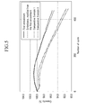
- FIG. 5 is a graph showing capacity change according to charge and discharge cycle of a rechargeable battery according to the first embodiment of the present invention.
- the rechargeable battery has a regular current of 5A and charged and discharged from 2.8V to 4.2V with 1C.
- a supporting part is formed by laminating 24 sheets of a film. It can be prepared to have an exact height through lamination rather than using one body. According to one embodiment modified from the first embodiment, a supporting part is formed by laminating 12 sheets of a film.
- a rechargeable battery of Comparative Example 1 has no supporting part.
- a rechargeable battery of Comparative Example 2 has no supporting part and has a non-uniform interface between the electrode assembly and the insulating member.
- an electrode assembly having a supporting part has little capacity change after 200 cycles of charges and discharges, but the one having no supporting part has a decreased capacity of about 98% capacity.
- the electrode assembly having a supporting part has a decreased capacity of approximately 96%, while the one having no supporting part has a decreased capacity of almost 93%.
- a rechargeable battery including a supporting part turned out to have higher capacity retention than one having no supporting part.
- the reason is that the supporting part supports an electrode assembly and maintains its uniform interface.
- the supporting part made of 24 sheets of a film had a little higher capacity retention than one made of 12 sheets of a film.
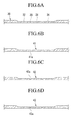
- FIGS. 6A to 6D shows a partial cross-sectional view of an insulating member according to the first embodiment and its modified embodiments of the present invention.
- an insulating member 30 includes a groove 35 on the boundary between a base 31 and supporting plates 32, 34, 36, and 38, so that the supporting plates can be easily folded.
- the groove 35 is formed to have a triangular cross-section on the top surface of the insulating member 30.
- the insulating member 41 may include a groove 41 a having a triangular cross-section on the bottom surface.
- the insulating member 42 may include a groove 42a having a quadrangular cross-section on the top surface.
- the insulating member 43 may include a groove 43a have a quadrangular cross-section on the bottom surface.
- FIG. 7 is a perspective view showing an insulating member according to Example 2 of the present invention.
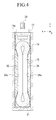
- FIG. 8 is a vertically cross-sectional view of a rechargeable battery according to Example 2 of the present invention.
- a rechargeable battery 200 according to the embodiment of the present invention has the same structure as one of the first embodiment except for an insulating member 50, it will not be illustrated in more detail.
- an insulating member 50 includes a base 51 closely attached to the bottom of a case 14, a first insulating plate 52 expanded from the first end 51 a of the base 51, and a second insulating plate 54 expanded from the second end 51 b of the base 51 opposing the first end 51 a.
- the insulating member 50 may include a third insulating plate 56 expanded from the third end 51 c crossing with the first end 51 a and a fourth insulating plate 58 expanded from the fourth end 51d facing the third end 51 c.
- the base 51 has a quadrangular shape and four ends 51 a, 51 b, 51 c, and 51d.
- the base 51 may be shaped to be an arc on the top surface where it contacts with an electrode assembly 15, so that it can stably support the electrode assembly 15 having the same arc-shaped bottom. Accordingly, the base 51 can stably support the electrode assembly 15 and prevent the electrode assembly 15 from shaking from an external impact. If the electrode assembly 15 shakes, the electrode assembly 15 may have bad contact with terminals 21 and 22. However, when a base 51 has an arc shape on top, it can more stably support an electrode assembly 15.
- the first insulating plate 52 includes a supporting part 52a closely attached to the flat part 15a of an electrode assembly 15 and supporting it.
- the supporting part 52a is shaped to be protruded and includes a buffering groove 52b in the center.
- the buffering groove 52b is at large quadrangular.
- the supporting part 52a is flat, where it contacts with the flat part 15a of an electrode assembly, and titled and curbed like an arc where it contacts with the convex part 15b. Since the convex part 15b contacts with a supporting part 52a at top and bottom of the flat part, the supporting part 52a needs to have two curbed parts 52c.
- the second insulating plate 54 includes a supporting part 54a closely attached to the flat part 15a of an electrode assembly 15.
- the supporting part is protruded and includes a buffering groove 54b in the center.
- the supporting part 54a is flat, where it contacts with the flat part 15a, and curbed 54c like an arc where it contacts with the convex part 15b.
- the curbed side 54c is closely attached to the convex part 15b of an electrode assembly 15.
- the curbed sides 52c and 54c play a role of supporting and pulling an electrode assembly at both ends. Accordingly, it can prevent the interface of the electrode assembly 15 from being non-uniform.
- buffering grooves 52b and 54b are formed in order to stably support the electrode assembly 15 and prevent its degradation
- the expanded electrode assembly 15 enters the buffering grooves 52b and 54b, alleviating the pressure thereon.
Landscapes
- Chemical & Material Sciences (AREA)
- Chemical Kinetics & Catalysis (AREA)
- Electrochemistry (AREA)
- General Chemical & Material Sciences (AREA)
- Engineering & Computer Science (AREA)
- Manufacturing & Machinery (AREA)
- Connection Of Batteries Or Terminals (AREA)
- Secondary Cells (AREA)
- Sealing Battery Cases Or Jackets (AREA)
- Cell Separators (AREA)
Abstract
Description
- This disclosure relates to a rechargeable battery. More particularly, this disclosure relates to a rechargeable battery including an insulating member having an improved structure between an electrode assembly and a case.
- A rechargeable battery can be recharged and discharged, unlike a primary battery that cannot be recharged. A rechargeable battery with low capacity is used for a small portable electronic device such as a mobile phone, a laptop computer, and a camcorder, while a rechargeable battery with large capacity is used as a power source for driving a motor such as for a hybrid vehicle.
- Recently, a rechargeable battery large has been developed to have large capacity, high power, and high energy density using a non-aqueous electrolyte. It can be used to drive a device, for example, a motor such as an electric vehicle requiring a large amount of electric power.
- Further, a rechargeable battery with high power is generally formed with a plurality of rechargeable batteries coupled in series or in parallel. This rechargeable battery may be cylindrical or prismatic.
- A prismatic rechargeable battery includes an electrode assembly including positive and negative electrodes and a separator therebetween, a case having a space for housing it, a cap plate closing and sealing the case and having a terminal hole through which a terminal is inserted, and a terminal inserted into the case and protruded outside of the case.
- The electrode assembly needs to be insulated from the case. However, it is difficult to install an insulating film between the electrode assembly and the case. In addition, the insulation film may be torn apart during the installation process. When torn apart, it may cause an internal short cut, resulting in more critical problems such as explosion of a rechargeable battery and the like.
- Herein, the electrode assembly is prepared by laminating positive and negative electrodes and a separator therebetween and then, spiral-winding them together, and pressing them into a flat jelly-roll. Accordingly, it has a dumbbell-shaped cross-section with both edges convex.
- However, since the flat part of the electrode assembly is relatively thinner than convex parts at the edges, it may not be stably attached to the interface of a supporting part.
- As a rechargeable battery is repetitively charged and discharged, the electrode assembly therein is also repetitively expanded and shrunk. When the electrode assembly irregularly repeats expansion and contraction, it may deteriorate performance of the rechargeable battery.
- In addition, the electrode assemblies may have a gap during the expansion. The gap may cause interfaces not to be uniform, resultantly deteriorating performance of a rechargeable battery.
- An exemplary embodiment of the present invention provides a rechargeable battery stably insulating an electrode assembly from a case but still maintaining the shape of the electrode assembly in order to solve the aforementioned problem.
- According to the embodiment of the present invention,
- According to the embodiment of the present invention, a rechargeable battery is provided comprising an electrode assembly having a first electrode, a second electrode, and a separator interposed between the first and the second electrodes. Further, a case for mounting the electrode assembly therein and an insulating member being disposed between side walls of the case and the electrode assembly to insulate the case from the electrode assembly are provided. An exploded-top view of the insulating member has the form of a cross. In other words, in an unfolded state, the insulating member is provided to have the form of a cross.
- According to the present invention, a rechargeable battery is provided including an insulating member between an electrode assembly and a case in order to stably insulate the electrode assembly from the case as well as uniformly maintain the interface of the electrode assembly and thereby, stably maintain capacity.
- The first electrode and the second electrode with the separator in-between are preferably wound into a jelly-roll.
- Preferably, the insulating member, when folded, matches the shape of the case. The shape of the surface of the insulating member being in contact with the electrode assembly is preferably designed to correspond to the outer shape of the electrode assembly.
- Thus, advantageously the insulating member forces the retention of the shape of an electrode assembly between the electrode assembly and a case.
- The insulating member preferably comprises a base in contact with the bottom of the case, a first insulating plate, a second insulating plate, a third insulating plate, and a fourth insulating plate, wherein all four insulating plates are attached to the base and are arranged to face the four side surfaces of the electrode assembly, respectively.
- The wound electrode assembly preferably comprises flat parts in its middle region and convex parts in its lower and upper parts, wherein the surfaces of the first and second insulating plates being in contact with the electrode assembly are formed such that their shape corresponds to the shape of the surface of the electrode assembly having flat and convex parts.
- In an embodiment, the first insulating plate comprises a first supporting part and the second insulating plate comprises a second supporting part, wherein the supporting parts are flat where they contact the respective flat part of the electrode assembly, and slanted or curved in the region of the respective convex part of the electrode assembly to correspond to the shape of the electrode assembly.
- The supporting part is preferably closely attached to the flat part of the electrode assembly and supports the electrode assembly. Alternatively or additionally, the supporting part is shaped to have a buffering groove adapted to allow expansion of the battery; and/or is flat in the region where it contacts the flat part of the electrode assembly. Alternatively or additionally, the supporting part may be tilted or curbed in an arc shape where it contacts the convex part of the electrode assembly; and/or may have a trapezoid-shaped cross-section.
- The buffering grooves advantageously help to stably support the electrode assembly and prevent its degradation.
- The supporting parts are designed to stably support the flat parts and also stably support the convex parts. Advantageously, while a rechargeable battery is repetitively charged and discharged, the electrode assembly therein is repetitively expanded and shrunk. Then, the supporting parts press the flat part of the electrode assembly between the case and the electrode assembly, maintaining the shape of the electrode assembly and preventing the interface from not being uniform. As a result, the inventive rechargeable battery exhibits improved capacity retention than a battery without support parts.
- The supporting parts may comprise film sheets laminated together.
- The film sheets further improve the capacity retention of the battery.
- The insulating member is preferably formed of one selected from the group consisting of poly propylene, poly ethylene, poly phenyl sulfate, poly buthylene terephthalate, poly tetrafluoro ethylene, perfluoroalkoxy, fluorinated ethylene propylene), poly vinylidene fluoride.
- The insulating member may have the form of a cuboid with the top open.
- The insulating member in one embodiment comprises a groove on the boundary between the base and the insulating plates, the groove being provided on the top of the surface of the base facing the electrode assembly or on the bottom of the surface of the base facing the case. The groove may have a triangular cross-section. It may also have a quadrangular cross-section.
- The third insulating plate and the fourth insulating plate are preferably of planar shape.
- The battery preferably further comprises a first terminal and a second terminal, the first terminal being connected to the first electrode via a first lead tab, the second terminal being connected to the second electrode via a second lead tab, wherein the third insulating plate is preferably disposed between the first lead tab and the case and the fourth insulating plate is preferably disposed between the second lead tab and the case.
- Advantageously, by the respective provision of the third and fourth insulating plates, the lead tabs are prevented from contacting the case.
- The base may have a quadrangular shape. The base may be provided with an arc-shaped top surface in the region of contact with the bottom of the electrode assembly. It may be closely attached to the bottom of the case. The base formed accordingly can stably support the electrode assembly having corresponding shapes.
-
-
FIG. 1 is an exploded perspective view of a rechargeable battery according to one embodiment. -
FIG. 2 is a perspective view of a rechargeable battery according to a first embodiment. -
FIG. 3 is a cross-sectional view taken along the III-III line ofFIG. 2 . -
FIG. 4 is a cross-sectional view taken along the IV-IV line ofFIG. 2 . -
FIG. 5 shows capacity change according to the charge and discharge cycle of rechargeable batteries of a first embodiment and comparative embodiment. -
FIG. 6a to 6d is a partial cross-sectional view showing an insulating member according to a first embodiment and other modified embodiments of the present invention. -
FIG. 7 is a perspective view showing an insulating member according to a second embodiment of the present invention. -
FIG. 8 is a vertically cross-sectional view of a rechargeable battery according to a second embodiment of the present invention. - The present invention will be described more fully hereinafter with reference to the accompanying drawings, in which exemplary embodiments of the invention are shown. As those skilled in the art would realize, the described embodiments may be modified in various different ways, all without departing from the scope of the present invention. In the specification and drawings, like reference numerals designate like elements
-
FIG. 1 is an exploded perspective view of a rechargeable battery according to one exemplary embodiment. - Referring to the drawing, the
rechargeable battery 100 includes anelectrode assembly 15 including apositive electrode 11 and anegative electrode 12 and aseparator 13 disposed therebetween, acase 14 having a space for housing it, acap plate 17 combined with anopening 14a of thecase 14, and apositive terminal 21 and anegative terminal 22 mounted on thecap plate 17 and electrically connected to theelectrode assembly 15. - The
positive electrode 11 and thenegative electrode 12 include a coated region coated with an active material on a current collector made of a thin metal foil plate anduncoated regions uncoated region 11a is formed at one end of thepositive electrode 11 along the length direction. The negativeuncoated region 12a is formed at the other end of thenegative electrode 12 along the length direction. - The
positive electrode 11 and thenegative electrode 12 are laminated with aseparator 13 as an insulator in the middle and then, spiral-wound into a jelly-roll, preparing anelectrode assembly 15. Theelectrode assembly 15 is pressed to be flat with a press and the like, so that it can be housed in thecase 14. The pressedassembly 15 is pushed toward both edges and expands to be convex there, forming aconvex part 15b. On the other hand, aflat part 15a is formed between the bothconvex parts 15b. -
FIG. 2 is a perspective view of a rechargeable battery according to a first embodiment,FIG. 3 is a cross-sectional view taken along the III-III line ofFIG. 2 , andFIG. 4 is a cross-sectional view taken along the IV-IV line ofFIG. 2 . - Referring to
FIGS. 2 to 4 , the lead tab 21 a of apositive terminal 21 at one edge of an electrode assembly is welded onto a positiveuncoated region 11a. The lead tab 22a of anegative terminal 22 is welded onto a negativeuncoated region 12a. - The
case 14 is made of a conductive metal such as aluminum, aluminum alloy, nickel-plated steel, or the like and formed as a hexahedron prism having a space for housing theelectrode assembly 15 and anopening 14a at one side. - As shown in
FIG. 1 , an insulatingmember 30 is disposed for electric insulation between thecase 14 and theelectrode assembly 15. The insulatingmember 30 has a cross shape and includes a base 31 closely attached to the bottom of acase 14, a first insulatingplate 32 extending from the first edge of thebase 31, and a second insulatingplate 34 extending from the second edge of thebase 31. In addition, the insulatingmember 30 includes athird plate 36 extending from athird end 31 c crossing with thefirst end 31 a and a fourth insulatingplate 38 extending from afourth end 31 d facing thethird end 31 c. - The insulating
member 30 may include one selected from the group consisting of PP(Poly Propylene), PE(poly ethylene), PPS(poly phenyl sulfate), PBT(Poly Buthylene Terephthalate), PTFE(Poly tetrafluoro ethylene), PFA(Perfluoroalkoxy), FEP(Fluorinated Ethylene Propylene), PVDF(Poly vinylidene fluoride). - This insulating
member 30, as shown inFIG. 1 , is positioned on theopening 14a of afirst case 14. It is inserted into thecase 14 together with theelectrode assembly 15, wherein the insulatingplates electrode assembly 15 is inserted into thecase 14. - The insulating
member 30 is at large mounted as an exploded cuboid with the top open. Accordingly, its first shape is a cross. The third insulatingplate 36, thebase 31, and the fourth insulatingplate 38 form one axis of the cross, the first insulatingplate 32, thebase 31, and the second insulatingplate 34 form the second, perpendicular part of the cross. Thus, the central crossing portion of the cross is established by thebase 31. The cross is preferably a symmetric cross, i.e. the third andfourth plates second plates base 31. - As aforementioned, a cross shaped insulating
member 30 can be bended and easily mounted between anelectrode assembly 15 and acase 14 when theelectrode assembly 15 is inserted into the case. - After the
electrode assembly 15 is inserted therein, anut 25 is screwed withterminals electrode assembly 15 on top. In addition, agasket 28 is installed between thenut 25 and thecap plate 17 for insulation. - Referring to
FIGS. 1 and4 , a supportingpart 32a is formed to be protruded on a first insulatingplate 32 to be closely attached to theflat part 15a of anelectrode assembly 15. In addition, another supportingpart 34a on a second insulatingplate 34 is formed to be closely attached to theflat part 15a on the other side of theelectrode assembly 15. - The supporting
parts electrode assembly 15. They have slanted ends, so that they can contact with the whole surface of theflat part 15a and theconvex part 15b right next to theflat part 15a. - In other words, the supporting
parts flat part 15a, and slanted, where they contact with aconvex part 15b, so that they can stably support theflat part 15a and also, stably contact with a part of theconvex part 15b. Accordingly, the supportingparts - On the other hand, the third insulating
plate 36 and the fourth insulatingplate 38 are disposed between lead tabs 21 a and 22a and acase 14, preventing the lead tabs 21 a and 22a from contacting with thecase 14. When an insulatingmember 30 is inserted into acase 14, it is shaped as a cuboid with the top open. - While a
rechargeable battery 100 is repetitively charged and discharged, theelectrode assembly 15 therein is repetitively expanded and shrunk. Then, the supportingparts flat part 15a of theelectrode assembly 15 between thecase 14 and theelectrode assembly 15, maintaining the shape of theelectrode assembly 15 and preventing the interface from not being uniform. -
FIG. 5 is a graph showing capacity change according to charge and discharge cycle of a rechargeable battery according to the first embodiment of the present invention. The rechargeable battery has a regular current of 5A and charged and discharged from 2.8V to 4.2V with 1C. - According to the first embodiment of the present invention, a supporting part is formed by laminating 24 sheets of a film. It can be prepared to have an exact height through lamination rather than using one body. According to one embodiment modified from the first embodiment, a supporting part is formed by laminating 12 sheets of a film. A rechargeable battery of Comparative Example 1 has no supporting part. A rechargeable battery of Comparative Example 2 has no supporting part and has a non-uniform interface between the electrode assembly and the insulating member.
- As shown in
FIG. 5 , an electrode assembly having a supporting part has little capacity change after 200 cycles of charges and discharges, but the one having no supporting part has a decreased capacity of about 98% capacity. In addition, after 400 cycles of charges and discharges, the electrode assembly having a supporting part has a decreased capacity of approximately 96%, while the one having no supporting part has a decreased capacity of almost 93%. - In conclusion, a rechargeable battery including a supporting part according to embodiments of the present invention turned out to have higher capacity retention than one having no supporting part. The reason is that the supporting part supports an electrode assembly and maintains its uniform interface. In addition, the supporting part made of 24 sheets of a film had a little higher capacity retention than one made of 12 sheets of a film.
-
FIGS. 6A to 6D shows a partial cross-sectional view of an insulating member according to the first embodiment and its modified embodiments of the present invention. - As shown in
FIG. 6A , an insulatingmember 30 includes agroove 35 on the boundary between a base 31 and supportingplates groove 35 is formed to have a triangular cross-section on the top surface of the insulatingmember 30. - In addition, as shown in
FIG. 6B , the insulatingmember 41 may include agroove 41 a having a triangular cross-section on the bottom surface. As shown inFIG. 6C , the insulatingmember 42 may include agroove 42a having a quadrangular cross-section on the top surface. In addition, as shown inFIG. 6D , the insulatingmember 43 may include agroove 43a have a quadrangular cross-section on the bottom surface. -
FIG. 7 is a perspective view showing an insulating member according to Example 2 of the present invention.FIG. 8 is a vertically cross-sectional view of a rechargeable battery according to Example 2 of the present invention. - Referring to
FIGS. 7 and8 , since arechargeable battery 200 according to the embodiment of the present invention has the same structure as one of the first embodiment except for an insulatingmember 50, it will not be illustrated in more detail. - According to the embodiment of the present invention, an insulating
member 50 includes a base 51 closely attached to the bottom of acase 14, a first insulatingplate 52 expanded from thefirst end 51 a of thebase 51, and a second insulatingplate 54 expanded from thesecond end 51 b of the base 51 opposing thefirst end 51 a. In addition, the insulatingmember 50 may include a third insulatingplate 56 expanded from thethird end 51 c crossing with thefirst end 51 a and a fourth insulatingplate 58 expanded from thefourth end 51d facing thethird end 51 c. - The
base 51 has a quadrangular shape and four ends 51 a, 51 b, 51 c, and 51d. - The base 51 may be shaped to be an arc on the top surface where it contacts with an
electrode assembly 15, so that it can stably support theelectrode assembly 15 having the same arc-shaped bottom. Accordingly, thebase 51 can stably support theelectrode assembly 15 and prevent theelectrode assembly 15 from shaking from an external impact. If theelectrode assembly 15 shakes, theelectrode assembly 15 may have bad contact withterminals base 51 has an arc shape on top, it can more stably support anelectrode assembly 15. - The first insulating
plate 52 includes a supportingpart 52a closely attached to theflat part 15a of anelectrode assembly 15 and supporting it. The supportingpart 52a is shaped to be protruded and includes abuffering groove 52b in the center. Thebuffering groove 52b is at large quadrangular. - The supporting
part 52a is flat, where it contacts with theflat part 15a of an electrode assembly, and titled and curbed like an arc where it contacts with theconvex part 15b. Since theconvex part 15b contacts with a supportingpart 52a at top and bottom of the flat part, the supportingpart 52a needs to have two curbedparts 52c. - The second insulating
plate 54 includes a supportingpart 54a closely attached to theflat part 15a of anelectrode assembly 15. The supporting part is protruded and includes abuffering groove 54b in the center. - The supporting
part 54a is flat, where it contacts with theflat part 15a, and curbed 54c like an arc where it contacts with theconvex part 15b. - When the supporting part is curbed like an
arc side 54c is closely attached to theconvex part 15b of anelectrode assembly 15. The curbed sides 52c and 54c play a role of supporting and pulling an electrode assembly at both ends. Accordingly, it can prevent the interface of theelectrode assembly 15 from being non-uniform. - In addition, since an
electrode assembly 15 is expanded during charges and discharges of arechargeable battery 200, it may be deteriorated itself and decrease cycle-life of therechargeable battery 200 when it is pressed. According to the embodiment of the present invention, bufferinggrooves electrode assembly 15 and prevent its degradation, - Accordingly, the expanded
electrode assembly 15 enters thebuffering grooves - While this invention has been described in connection with what is presently considered to be practical exemplary embodiments, it is to be understood that the invention is not limited to the disclosed embodiments, but, on the contrary, is intended to cover various modifications and equivalent arrangements included within the scope of the appended claims.
Claims (15)
- A rechargeable battery comprising:an electrode assembly (15) having a first electrode (11), a second electrode (12), and a separator (13) interposed between the first and the second electrodes (11, 12);a case (14) for mounting the electrode assembly (15) therein; andan insulating member (30, 41, 42, 43, 50) being disposed between side walls of the case (14) and the electrode assembly (15) to insulate the case (14) from the electrode assembly (15),characterized in thatan exploded-view of the insulating member (30, 41, 42, 43, 50) has the form of a cross.
- Rechargeable battery according to claim 1, wherein the insulating member (30, 41, 42, 43, 50), when folded, matches the shape of the case.
- Rechargeable battery according to claim 1 or 2, wherein the first electrode (11) and the second electrode (12) with the separator (13) in-between are being wound into a jelly-roll.
- Rechargeable battery according to any of the previous claims, wherein the shape of the surface of the insulating member (30, 41, 42, 43, 50) being in contact with the electrode assembly (15) is designed to correspond to the outer shape of the electrode assembly (15).
- Rechargeable battery according to any of the previous claims, wherein the insulating member (30, 41, 42, 43, 50) comprises a base (31, 51) in contact with the bottom of the case (14); a first insulating plate (32, 52); a second insulating plate (34, 54); a third insulating plate (36, 56); and a fourth insulating plate (38, 58), wherein all four insulating plates are attached to the base (31, 51) and are arranged to face the four side surfaces of the electrode assembly (15), respectively.
- Rechargeable battery according to any of claims 3 to 5, wherein the wound electrode assembly (15) comprises flat parts (15a) in its middle region and convex parts (15b) in its lower and upper parts, wherein the surfaces of the first and second insulating plates (32, 52; 34, 54) being in contact with the electrode assembly (15) are formed such that their shape corresponds to the shape surface of the electrode assembly (15) having flat and convex parts (15a, 15b).
- Rechargeable battery according to claim 6, wherein the first insulating plate (32, 52) comprises a first supporting part (32a, 52a) and the second insulating plate (34, 54) comprises a second supporting part (34a, 54a), wherein the supporting parts (32a, 52a; 34a, 54a):are flat where they contact the respective flat part (15a) of the electrode assembly (15), andslanted or curved in the region of the respective convex part (15b) of the electrode assembly (15) to correspond to the shape of the electrode assembly (15).
- Rechargeable battery according to claim 7, wherein the supporting part (32a, 52a; 34a, 54a) comprises at least one of the following features:the supporting part is closely attached to the flat part (15a) of the electrode assembly (15) and supports the electrode assembly (15);is shaped to have a buffering groove (52b) adapted to allow expansion of the battery;is flat in the region where it contacts the flat part (15a) of the electrode assembly (15);is tilted or curbed in an arc shape where it contacts the convex part (15b) of the electrode assembly; andhas a trapezoid-shaped cross-section.
- Rechargeable battery according to claim 7 or 8, wherein the supporting parts (32a, 52a; 34a, 54a) comprise film sheets laminated together.
- Rechargeable battery according to any of the previous claims, wherein the insulating member (30, 41, 42, 43, 50) is formed of one selected from the group consisting of poly propylene, poly ethylene, poly phenyl sulfate, poly buthylene terephthalate, poly tetrafluoro ethylene, perfluoroalkoxy, fluorinated ethylene propylene), poly vinylidene fluoride.
- Rechargeable battery according to any of the previous claims, wherein the insulating member (30, 41, 42, 43, 50) has the form of a cuboid with the top open.
- Rechargeable battery according to any of the previous claims, wherein the insulating member (30, 41, 42, 43, 50) comprises a groove (35) on the boundary between the base (31) and the insulating plates (32, 34, 36, 38), the groove (35):being provided on the top of the surface of the base (31) facing the electrode assembly (15) or on the bottom of the surface of the base (31) facing the case (14); and/orhaving a triangular cross-section; and/orhaving a quadrangular cross-section.
- Rechargeable battery according to any of the previous claims, wherein the third insulating plate (36, 56) and the fourth insulating plate (38, 58) are of planar shape.
- Rechargeable battery according to any of the previous claims, wherein the battery further comprises a first terminal (21) and a second terminal (22), the first terminal (21) being connected to the first electrode (11) via a first lead tab (21 a), the second terminal (22) being connected to the second electrode (12) via a second lead tab (22a), wherein the third insulating plate (36, 56) is disposed between the first lead tab (21 a) and the case (14) and the fourth insulating plate (38, 58) is disposed between the second lead tab (22a) and the case (14).
- Rechargeable battery according to any of the previous claims, wherein the base (31, 51):has a quadrangular shape; and/oris provided with an arc-shaped top surface in the region of contact with the bottom of the electrode assembly (15); and/oris closely attached to the bottom of the case (14).
Applications Claiming Priority (2)
| Application Number | Priority Date | Filing Date | Title |
|---|---|---|---|
| US23904409P | 2009-09-01 | 2009-09-01 | |
| US12/706,358 US8697272B2 (en) | 2009-09-01 | 2010-02-16 | Secondary battery having an insulating member |
Publications (2)
| Publication Number | Publication Date |
|---|---|
| EP2290732A1 true EP2290732A1 (en) | 2011-03-02 |
| EP2290732B1 EP2290732B1 (en) | 2012-05-09 |
Family
ID=42727424
Family Applications (1)
| Application Number | Title | Priority Date | Filing Date |
|---|---|---|---|
| EP10169597A Active EP2290732B1 (en) | 2009-09-01 | 2010-07-15 | Secondary battery with insulating member |
Country Status (6)
| Country | Link |
|---|---|
| US (1) | US8697272B2 (en) |
| EP (1) | EP2290732B1 (en) |
| JP (1) | JP5297424B2 (en) |
| KR (1) | KR101191661B1 (en) |
| CN (1) | CN102005602B (en) |
| AT (1) | ATE557435T1 (en) |
Cited By (6)
| Publication number | Priority date | Publication date | Assignee | Title |
|---|---|---|---|---|
| EP2639850A1 (en) * | 2012-03-12 | 2013-09-18 | GS Yuasa International Ltd. | Electric Storage Device |
| EP2804234A1 (en) * | 2013-05-15 | 2014-11-19 | Samsung SDI Co., Ltd. | Rechargeable battery with insulation member having two insulation portions |
| EP2590252A3 (en) * | 2011-11-04 | 2015-04-22 | Samsung SDI Co., Ltd. | Rechargeable battery and method for manufacturing the same |
| EP2866279A4 (en) * | 2012-06-26 | 2016-03-02 | Toyota Jidoshokki Kk | Accumulator device |
| CN105474429A (en) * | 2013-08-23 | 2016-04-06 | 丰田自动车株式会社 | Nonaqueous electrolyte battery and manufacturing method thereof |
| WO2021091064A1 (en) * | 2019-11-08 | 2021-05-14 | 삼성에스디아이(주) | Secondary battery |
Families Citing this family (40)
| Publication number | Priority date | Publication date | Assignee | Title |
|---|---|---|---|---|
| CN102356496B (en) * | 2010-05-21 | 2014-07-23 | 丰田自动车株式会社 | Secondary battery |
| KR101126809B1 (en) * | 2010-06-16 | 2012-03-23 | 에스비리모티브 주식회사 | Secondary Battery |
| JP5673355B2 (en) * | 2011-05-27 | 2015-02-18 | 株式会社Gsユアサ | battery |
| US9472802B2 (en) * | 2011-07-25 | 2016-10-18 | Samsung Sdi Co., Ltd. | Secondary battery |
| KR20130049025A (en) * | 2011-11-03 | 2013-05-13 | 삼성에스디아이 주식회사 | Rechargeable battery |
| DE102011088636A1 (en) * | 2011-12-15 | 2013-06-20 | Robert Bosch Gmbh | Hard shell housing with superhydrophobic material |
| DE102012206075A1 (en) * | 2011-12-15 | 2013-06-20 | Robert Bosch Gmbh | Hard shell cell housing with vapor barrier coating |
| JP6102058B2 (en) * | 2012-02-15 | 2017-03-29 | 株式会社Gsユアサ | Electricity storage element |
| JP5719859B2 (en) * | 2012-02-29 | 2015-05-20 | 株式会社半導体エネルギー研究所 | Power storage device |
| KR102115624B1 (en) * | 2012-03-12 | 2020-05-26 | 가부시키가이샤 지에스 유아사 | Electric storage device |
| JP6052574B2 (en) * | 2012-05-16 | 2016-12-27 | 株式会社Gsユアサ | Power storage device and method for manufacturing power storage device |
| DE102012208239A1 (en) * | 2012-05-16 | 2013-11-21 | Robert Bosch Gmbh | battery assembly |
| US9905369B2 (en) * | 2012-05-22 | 2018-02-27 | Gs Yuasa International Ltd. | Energy storage device |
| DE102012214443A1 (en) * | 2012-08-14 | 2014-02-20 | Robert Bosch Gmbh | Warping of battery cells by a cambered configuration of the battery case |
| WO2014054734A1 (en) * | 2012-10-03 | 2014-04-10 | 新神戸電機株式会社 | Secondary battery |
| FR2997559B1 (en) * | 2012-10-31 | 2016-12-09 | Renault Sa | THERMAL BATTERY PROTECTION ENVELOPE FOR MOTOR VEHICLE |
| KR101454117B1 (en) * | 2013-02-20 | 2014-10-27 | 주식회사 엘지화학 | Packaging film for display apparatus and display apparatus comprising the same |
| KR20140120189A (en) * | 2013-04-02 | 2014-10-13 | 삼성에스디아이 주식회사 | Rechargeable battery and manufacturing method of the same |
| JP5742869B2 (en) * | 2013-04-16 | 2015-07-01 | 株式会社豊田自動織機 | Power storage device |
| JP5841571B2 (en) * | 2013-07-31 | 2016-01-13 | 日立オートモティブシステムズ株式会社 | Secondary battery |
| JP2015060712A (en) * | 2013-09-18 | 2015-03-30 | 株式会社東芝 | Secondary battery |
| JP6414731B2 (en) * | 2013-10-01 | 2018-10-31 | 株式会社Gsユアサ | Power storage element and power storage device |
| KR102195727B1 (en) * | 2014-01-06 | 2020-12-28 | 삼성에스디아이 주식회사 | Secondary battery |
| KR102257678B1 (en) * | 2014-03-28 | 2021-05-28 | 삼성에스디아이 주식회사 | Secondary battery |
| JP6264196B2 (en) * | 2014-05-30 | 2018-01-24 | 三洋電機株式会社 | Prismatic secondary battery |
| KR102201306B1 (en) | 2014-06-17 | 2021-01-11 | 삼성에스디아이 주식회사 | Secondary Battery |
| JP6815716B2 (en) * | 2014-12-11 | 2021-01-20 | 株式会社Gsユアサ | Power storage element |
| JP6331097B2 (en) * | 2015-01-14 | 2018-05-30 | トヨタ自動車株式会社 | Manufacturing method of secondary battery |
| JP6506576B2 (en) * | 2015-03-13 | 2019-04-24 | マクセルホールディングス株式会社 | battery |
| JP6686286B2 (en) * | 2015-03-30 | 2020-04-22 | 三洋電機株式会社 | Prismatic secondary battery and assembled battery using the same |
| JP6264663B2 (en) | 2015-04-03 | 2018-01-24 | トヨタ自動車株式会社 | battery |
| JP6521779B2 (en) * | 2015-07-23 | 2019-05-29 | 日立オートモティブシステムズ株式会社 | Secondary battery |
| US10930965B2 (en) | 2016-10-25 | 2021-02-23 | Altergy Systems | Collapsing fuel cell isolator for fuel cell airflow management |
| JP6878914B2 (en) * | 2017-01-26 | 2021-06-02 | 株式会社豊田自動織機 | Power storage device |
| KR20180097085A (en) | 2017-02-22 | 2018-08-30 | 삼성에스디아이 주식회사 | Secondary battery having a structure capable of suppressing short circuit of multi-tap |
| JP6967192B2 (en) * | 2018-02-09 | 2021-11-17 | トヨタ自動車株式会社 | Secondary battery and assembled battery |
| DE102018202935A1 (en) * | 2018-02-27 | 2019-08-29 | Bayerische Motoren Werke Aktiengesellschaft | Energy storage cell and method for producing an energy storage cell |
| JP7068632B2 (en) * | 2018-12-11 | 2022-05-17 | トヨタ自動車株式会社 | battery |
| US20210305632A1 (en) * | 2020-03-25 | 2021-09-30 | Gs Yuasa International Ltd. | Energy storage device |
| WO2023097574A1 (en) * | 2021-12-01 | 2023-06-08 | 宁德时代新能源科技股份有限公司 | Battery cell and manufacturing method and device therefor, battery, and electrical apparatus |
Citations (5)
| Publication number | Priority date | Publication date | Assignee | Title |
|---|---|---|---|---|
| BE400376A (en) * | ||||
| EP0469776A2 (en) * | 1990-07-30 | 1992-02-05 | Eveready Battery Company, Inc. | Separators for electrochemical cells |
| US20060024568A1 (en) * | 2004-07-28 | 2006-02-02 | Lee Sang-Won | Rechargeable battery |
| US20060093902A1 (en) * | 2004-09-24 | 2006-05-04 | Lee Jin U | Lithium secondary battery and method for manufacturing the same |
| JP2009048966A (en) * | 2007-08-23 | 2009-03-05 | Toyota Motor Corp | Battery, and manufacturing method thereof |
Family Cites Families (12)
| Publication number | Priority date | Publication date | Assignee | Title |
|---|---|---|---|---|
| JPH0582158A (en) | 1991-09-24 | 1993-04-02 | Matsushita Electric Ind Co Ltd | Sealed rectangular alkaline storage battery |
| JPH07261678A (en) | 1994-03-22 | 1995-10-13 | Rohm Co Ltd | Led display device and method for coating case of led display device |
| JP3709628B2 (en) | 1995-11-15 | 2005-10-26 | ソニー株式会社 | Non-aqueous electrolyte secondary battery |
| JPH1131523A (en) | 1997-02-19 | 1999-02-02 | Sony Corp | Nonaqueous electrolyte secondary battery and manufacture thereof |
| TW420886B (en) * | 1997-12-19 | 2001-02-01 | Celgard Inc | Penta-layer battery separator |
| JPH11288703A (en) | 1998-04-01 | 1999-10-19 | Gs Melcotec Kk | Battery |
| US20040137321A1 (en) | 2002-11-27 | 2004-07-15 | Jean-Francois Savaria | Casing for an energy storage device |
| JP2005032477A (en) | 2003-07-08 | 2005-02-03 | Toyota Motor Corp | Battery and automobile mounting it |
| JP2006040684A (en) | 2004-07-27 | 2006-02-09 | Matsushita Electric Ind Co Ltd | Sealed rectangular battery |
| JP2006278245A (en) | 2005-03-30 | 2006-10-12 | Toyota Motor Corp | Battery and its manufacturing method |
| KR100669435B1 (en) | 2005-04-08 | 2007-01-15 | 삼성에스디아이 주식회사 | Secondary battery |
| JP5085950B2 (en) | 2006-02-07 | 2012-11-28 | 三洋電機株式会社 | Battery case, battery and non-aqueous electrolyte secondary battery |
-
2010
- 2010-02-16 US US12/706,358 patent/US8697272B2/en active Active
- 2010-02-18 KR KR1020100014786A patent/KR101191661B1/en active IP Right Grant
- 2010-07-15 AT AT10169597T patent/ATE557435T1/en active
- 2010-07-15 EP EP10169597A patent/EP2290732B1/en active Active
- 2010-08-19 JP JP2010184437A patent/JP5297424B2/en active Active
- 2010-08-27 CN CN2010102668353A patent/CN102005602B/en active Active
Patent Citations (5)
| Publication number | Priority date | Publication date | Assignee | Title |
|---|---|---|---|---|
| BE400376A (en) * | ||||
| EP0469776A2 (en) * | 1990-07-30 | 1992-02-05 | Eveready Battery Company, Inc. | Separators for electrochemical cells |
| US20060024568A1 (en) * | 2004-07-28 | 2006-02-02 | Lee Sang-Won | Rechargeable battery |
| US20060093902A1 (en) * | 2004-09-24 | 2006-05-04 | Lee Jin U | Lithium secondary battery and method for manufacturing the same |
| JP2009048966A (en) * | 2007-08-23 | 2009-03-05 | Toyota Motor Corp | Battery, and manufacturing method thereof |
Cited By (8)
| Publication number | Priority date | Publication date | Assignee | Title |
|---|---|---|---|---|
| EP2590252A3 (en) * | 2011-11-04 | 2015-04-22 | Samsung SDI Co., Ltd. | Rechargeable battery and method for manufacturing the same |
| EP2639850A1 (en) * | 2012-03-12 | 2013-09-18 | GS Yuasa International Ltd. | Electric Storage Device |
| US9065082B2 (en) | 2012-03-12 | 2015-06-23 | Gs Yuasa International Ltd. | Electric storage device |
| EP2866279A4 (en) * | 2012-06-26 | 2016-03-02 | Toyota Jidoshokki Kk | Accumulator device |
| EP2804234A1 (en) * | 2013-05-15 | 2014-11-19 | Samsung SDI Co., Ltd. | Rechargeable battery with insulation member having two insulation portions |
| US10014495B2 (en) | 2013-05-15 | 2018-07-03 | Samsung Sdi Co., Ltd. | Rechargeable battery |
| CN105474429A (en) * | 2013-08-23 | 2016-04-06 | 丰田自动车株式会社 | Nonaqueous electrolyte battery and manufacturing method thereof |
| WO2021091064A1 (en) * | 2019-11-08 | 2021-05-14 | 삼성에스디아이(주) | Secondary battery |
Also Published As
| Publication number | Publication date |
|---|---|
| JP5297424B2 (en) | 2013-09-25 |
| CN102005602A (en) | 2011-04-06 |
| ATE557435T1 (en) | 2012-05-15 |
| EP2290732B1 (en) | 2012-05-09 |
| KR20110025036A (en) | 2011-03-09 |
| JP2011054567A (en) | 2011-03-17 |
| KR101191661B1 (en) | 2012-10-17 |
| CN102005602B (en) | 2013-08-07 |
| US20110052975A1 (en) | 2011-03-03 |
| US8697272B2 (en) | 2014-04-15 |
Similar Documents
| Publication | Publication Date | Title |
|---|---|---|
| EP2290732B1 (en) | Secondary battery with insulating member | |
| US7981540B2 (en) | Rechargeable battery | |
| US8440336B2 (en) | Rechargeable battery with short circuit member | |
| US7364817B2 (en) | Secondary battery and method of manufacturing the same | |
| JP5241792B2 (en) | Secondary battery | |
| KR101106998B1 (en) | Rechargeable battery | |
| US9040191B2 (en) | Rechargeable battery | |
| JP5424218B2 (en) | Secondary battery | |
| KR100846955B1 (en) | cylindrical secondary battery | |
| KR101030916B1 (en) | Secondary Battery | |
| EP2595214B1 (en) | Rechargeable battery | |
| US20060063068A1 (en) | Secondary battery | |
| JP5297441B2 (en) | Secondary battery | |
| EP2309582A2 (en) | Rechargeable battery and method of manufacturing same | |
| US10763489B2 (en) | Rechargeable battery having membrane | |
| US20130040191A1 (en) | Rechargeable battery | |
| US20130115494A1 (en) | Rechargeable battery | |
| EP2048723B1 (en) | Battery module | |
| EP3509127B1 (en) | Secondary battery | |
| US20090087724A1 (en) | Rechargeable battery | |
| EP2330660B1 (en) | Rechargeable battery | |
| KR101320581B1 (en) | Secondary battery |
Legal Events
| Date | Code | Title | Description |
|---|---|---|---|
| PUAI | Public reference made under article 153(3) epc to a published international application that has entered the european phase |
Free format text: ORIGINAL CODE: 0009012 |
|
| 17P | Request for examination filed |
Effective date: 20100715 |
|
| AK | Designated contracting states |
Kind code of ref document: A1 Designated state(s): AL AT BE BG CH CY CZ DE DK EE ES FI FR GB GR HR HU IE IS IT LI LT LU LV MC MK MT NL NO PL PT RO SE SI SK SM TR |
|
| AX | Request for extension of the european patent |
Extension state: BA ME RS |
|
| 17Q | First examination report despatched |
Effective date: 20110210 |
|
| RIC1 | Information provided on ipc code assigned before grant |
Ipc: H01M 2/18 20060101AFI20110601BHEP |
|
| GRAP | Despatch of communication of intention to grant a patent |
Free format text: ORIGINAL CODE: EPIDOSNIGR1 |
|
| GRAS | Grant fee paid |
Free format text: ORIGINAL CODE: EPIDOSNIGR3 |
|
| GRAA | (expected) grant |
Free format text: ORIGINAL CODE: 0009210 |
|
| AK | Designated contracting states |
Kind code of ref document: B1 Designated state(s): AL AT BE BG CH CY CZ DE DK EE ES FI FR GB GR HR HU IE IS IT LI LT LU LV MC MK MT NL NO PL PT RO SE SI SK SM TR |
|
| REG | Reference to a national code |
Ref country code: GB Ref legal event code: FG4D |
|
| REG | Reference to a national code |
Ref country code: AT Ref legal event code: REF Ref document number: 557435 Country of ref document: AT Kind code of ref document: T Effective date: 20120515 Ref country code: CH Ref legal event code: EP |
|
| REG | Reference to a national code |
Ref country code: IE Ref legal event code: FG4D |
|
| REG | Reference to a national code |
Ref country code: DE Ref legal event code: R096 Ref document number: 602010001403 Country of ref document: DE Effective date: 20120712 |
|
| REG | Reference to a national code |
Ref country code: NL Ref legal event code: VDEP Effective date: 20120509 |
|
| REG | Reference to a national code |
Ref country code: LT Ref legal event code: MG4D Effective date: 20120509 |
|
| PG25 | Lapsed in a contracting state [announced via postgrant information from national office to epo] |
Ref country code: CY Free format text: LAPSE BECAUSE OF FAILURE TO SUBMIT A TRANSLATION OF THE DESCRIPTION OR TO PAY THE FEE WITHIN THE PRESCRIBED TIME-LIMIT Effective date: 20120509 Ref country code: NO Free format text: LAPSE BECAUSE OF FAILURE TO SUBMIT A TRANSLATION OF THE DESCRIPTION OR TO PAY THE FEE WITHIN THE PRESCRIBED TIME-LIMIT Effective date: 20120809 Ref country code: PL Free format text: LAPSE BECAUSE OF FAILURE TO SUBMIT A TRANSLATION OF THE DESCRIPTION OR TO PAY THE FEE WITHIN THE PRESCRIBED TIME-LIMIT Effective date: 20120509 Ref country code: FI Free format text: LAPSE BECAUSE OF FAILURE TO SUBMIT A TRANSLATION OF THE DESCRIPTION OR TO PAY THE FEE WITHIN THE PRESCRIBED TIME-LIMIT Effective date: 20120509 Ref country code: SE Free format text: LAPSE BECAUSE OF FAILURE TO SUBMIT A TRANSLATION OF THE DESCRIPTION OR TO PAY THE FEE WITHIN THE PRESCRIBED TIME-LIMIT Effective date: 20120509 Ref country code: LT Free format text: LAPSE BECAUSE OF FAILURE TO SUBMIT A TRANSLATION OF THE DESCRIPTION OR TO PAY THE FEE WITHIN THE PRESCRIBED TIME-LIMIT Effective date: 20120509 Ref country code: IS Free format text: LAPSE BECAUSE OF FAILURE TO SUBMIT A TRANSLATION OF THE DESCRIPTION OR TO PAY THE FEE WITHIN THE PRESCRIBED TIME-LIMIT Effective date: 20120909 |
|
| REG | Reference to a national code |
Ref country code: AT Ref legal event code: MK05 Ref document number: 557435 Country of ref document: AT Kind code of ref document: T Effective date: 20120509 |
|
| PG25 | Lapsed in a contracting state [announced via postgrant information from national office to epo] |
Ref country code: PT Free format text: LAPSE BECAUSE OF FAILURE TO SUBMIT A TRANSLATION OF THE DESCRIPTION OR TO PAY THE FEE WITHIN THE PRESCRIBED TIME-LIMIT Effective date: 20120910 Ref country code: HR Free format text: LAPSE BECAUSE OF FAILURE TO SUBMIT A TRANSLATION OF THE DESCRIPTION OR TO PAY THE FEE WITHIN THE PRESCRIBED TIME-LIMIT Effective date: 20120509 Ref country code: SI Free format text: LAPSE BECAUSE OF FAILURE TO SUBMIT A TRANSLATION OF THE DESCRIPTION OR TO PAY THE FEE WITHIN THE PRESCRIBED TIME-LIMIT Effective date: 20120509 Ref country code: LV Free format text: LAPSE BECAUSE OF FAILURE TO SUBMIT A TRANSLATION OF THE DESCRIPTION OR TO PAY THE FEE WITHIN THE PRESCRIBED TIME-LIMIT Effective date: 20120509 Ref country code: GR Free format text: LAPSE BECAUSE OF FAILURE TO SUBMIT A TRANSLATION OF THE DESCRIPTION OR TO PAY THE FEE WITHIN THE PRESCRIBED TIME-LIMIT Effective date: 20120810 |
|
| PG25 | Lapsed in a contracting state [announced via postgrant information from national office to epo] |
Ref country code: BE Free format text: LAPSE BECAUSE OF FAILURE TO SUBMIT A TRANSLATION OF THE DESCRIPTION OR TO PAY THE FEE WITHIN THE PRESCRIBED TIME-LIMIT Effective date: 20120509 |
|
| PG25 | Lapsed in a contracting state [announced via postgrant information from national office to epo] |
Ref country code: SK Free format text: LAPSE BECAUSE OF FAILURE TO SUBMIT A TRANSLATION OF THE DESCRIPTION OR TO PAY THE FEE WITHIN THE PRESCRIBED TIME-LIMIT Effective date: 20120509 Ref country code: NL Free format text: LAPSE BECAUSE OF FAILURE TO SUBMIT A TRANSLATION OF THE DESCRIPTION OR TO PAY THE FEE WITHIN THE PRESCRIBED TIME-LIMIT Effective date: 20120509 Ref country code: RO Free format text: LAPSE BECAUSE OF FAILURE TO SUBMIT A TRANSLATION OF THE DESCRIPTION OR TO PAY THE FEE WITHIN THE PRESCRIBED TIME-LIMIT Effective date: 20120509 Ref country code: EE Free format text: LAPSE BECAUSE OF FAILURE TO SUBMIT A TRANSLATION OF THE DESCRIPTION OR TO PAY THE FEE WITHIN THE PRESCRIBED TIME-LIMIT Effective date: 20120509 Ref country code: DK Free format text: LAPSE BECAUSE OF FAILURE TO SUBMIT A TRANSLATION OF THE DESCRIPTION OR TO PAY THE FEE WITHIN THE PRESCRIBED TIME-LIMIT Effective date: 20120509 Ref country code: AT Free format text: LAPSE BECAUSE OF FAILURE TO SUBMIT A TRANSLATION OF THE DESCRIPTION OR TO PAY THE FEE WITHIN THE PRESCRIBED TIME-LIMIT Effective date: 20120509 Ref country code: CZ Free format text: LAPSE BECAUSE OF FAILURE TO SUBMIT A TRANSLATION OF THE DESCRIPTION OR TO PAY THE FEE WITHIN THE PRESCRIBED TIME-LIMIT Effective date: 20120509 |
|
| REG | Reference to a national code |
Ref country code: DE Ref legal event code: R097 Ref document number: 602010001403 Country of ref document: DE |
|
| PG25 | Lapsed in a contracting state [announced via postgrant information from national office to epo] |
Ref country code: IT Free format text: LAPSE BECAUSE OF FAILURE TO SUBMIT A TRANSLATION OF THE DESCRIPTION OR TO PAY THE FEE WITHIN THE PRESCRIBED TIME-LIMIT Effective date: 20120509 Ref country code: MK Free format text: LAPSE BECAUSE OF FAILURE TO SUBMIT A TRANSLATION OF THE DESCRIPTION OR TO PAY THE FEE WITHIN THE PRESCRIBED TIME-LIMIT Effective date: 20120509 Ref country code: MC Free format text: LAPSE BECAUSE OF NON-PAYMENT OF DUE FEES Effective date: 20120731 |
|
| PLBE | No opposition filed within time limit |
Free format text: ORIGINAL CODE: 0009261 |
|
| STAA | Information on the status of an ep patent application or granted ep patent |
Free format text: STATUS: NO OPPOSITION FILED WITHIN TIME LIMIT |
|
| REG | Reference to a national code |
Ref country code: FR Ref legal event code: TQ Owner name: ROBERT BOSCH GMBH, DE Effective date: 20130218 Ref country code: FR Ref legal event code: TQ Owner name: SAMSUNG SDI CO., LTD., KR Effective date: 20130218 |
|
| 26N | No opposition filed |
Effective date: 20130212 |
|
| REG | Reference to a national code |
Ref country code: DE Ref legal event code: R082 Ref document number: 602010001403 Country of ref document: DE Representative=s name: GULDE HENGELHAUPT ZIEBIG & SCHNEIDER, DE Effective date: 20130221 Ref country code: DE Ref legal event code: R081 Ref document number: 602010001403 Country of ref document: DE Owner name: ROBERT BOSCH GMBH, DE Free format text: FORMER OWNER: SB LIMOTIVE CO., LTD., YONGIN, KR Effective date: 20130221 Ref country code: DE Ref legal event code: R081 Ref document number: 602010001403 Country of ref document: DE Owner name: SAMSUNG SDI CO., LTD., KR Free format text: FORMER OWNER: SB LIMOTIVE CO., LTD., YONGIN, KR Effective date: 20130221 Ref country code: DE Ref legal event code: R082 Ref document number: 602010001403 Country of ref document: DE Representative=s name: GULDE & PARTNER PATENT- UND RECHTSANWALTSKANZL, DE Effective date: 20130221 Ref country code: DE Ref legal event code: R081 Ref document number: 602010001403 Country of ref document: DE Owner name: ROBERT BOSCH GMBH, DE Free format text: FORMER OWNER: SB LIMOTIVE CO., LTD., YONGIN, KYONGGI, KR Effective date: 20130221 Ref country code: DE Ref legal event code: R081 Ref document number: 602010001403 Country of ref document: DE Owner name: SAMSUNG SDI CO., LTD., YONGIN, KR Free format text: FORMER OWNER: SB LIMOTIVE CO., LTD., YONGIN, KYONGGI, KR Effective date: 20130221 |
|
| PG25 | Lapsed in a contracting state [announced via postgrant information from national office to epo] |
Ref country code: ES Free format text: LAPSE BECAUSE OF FAILURE TO SUBMIT A TRANSLATION OF THE DESCRIPTION OR TO PAY THE FEE WITHIN THE PRESCRIBED TIME-LIMIT Effective date: 20120820 |
|
| REG | Reference to a national code |
Ref country code: IE Ref legal event code: MM4A |
|
| REG | Reference to a national code |
Ref country code: GB Ref legal event code: 732E Free format text: REGISTERED BETWEEN 20130418 AND 20130424 |
|
| REG | Reference to a national code |
Ref country code: DE Ref legal event code: R097 Ref document number: 602010001403 Country of ref document: DE Effective date: 20130212 |
|
| PG25 | Lapsed in a contracting state [announced via postgrant information from national office to epo] |
Ref country code: MT Free format text: LAPSE BECAUSE OF FAILURE TO SUBMIT A TRANSLATION OF THE DESCRIPTION OR TO PAY THE FEE WITHIN THE PRESCRIBED TIME-LIMIT Effective date: 20120509 Ref country code: BG Free format text: LAPSE BECAUSE OF FAILURE TO SUBMIT A TRANSLATION OF THE DESCRIPTION OR TO PAY THE FEE WITHIN THE PRESCRIBED TIME-LIMIT Effective date: 20120809 Ref country code: IE Free format text: LAPSE BECAUSE OF NON-PAYMENT OF DUE FEES Effective date: 20120715 |
|
| PG25 | Lapsed in a contracting state [announced via postgrant information from national office to epo] |
Ref country code: AL Free format text: LAPSE BECAUSE OF FAILURE TO SUBMIT A TRANSLATION OF THE DESCRIPTION OR TO PAY THE FEE WITHIN THE PRESCRIBED TIME-LIMIT Effective date: 20120509 |
|
| PG25 | Lapsed in a contracting state [announced via postgrant information from national office to epo] |
Ref country code: TR Free format text: LAPSE BECAUSE OF FAILURE TO SUBMIT A TRANSLATION OF THE DESCRIPTION OR TO PAY THE FEE WITHIN THE PRESCRIBED TIME-LIMIT Effective date: 20120509 |
|
| PG25 | Lapsed in a contracting state [announced via postgrant information from national office to epo] |
Ref country code: SM Free format text: LAPSE BECAUSE OF FAILURE TO SUBMIT A TRANSLATION OF THE DESCRIPTION OR TO PAY THE FEE WITHIN THE PRESCRIBED TIME-LIMIT Effective date: 20120509 Ref country code: LU Free format text: LAPSE BECAUSE OF NON-PAYMENT OF DUE FEES Effective date: 20120715 |
|
| PG25 | Lapsed in a contracting state [announced via postgrant information from national office to epo] |
Ref country code: HU Free format text: LAPSE BECAUSE OF FAILURE TO SUBMIT A TRANSLATION OF THE DESCRIPTION OR TO PAY THE FEE WITHIN THE PRESCRIBED TIME-LIMIT Effective date: 20100715 |
|
| REG | Reference to a national code |
Ref country code: CH Ref legal event code: PL |
|
| PG25 | Lapsed in a contracting state [announced via postgrant information from national office to epo] |
Ref country code: LI Free format text: LAPSE BECAUSE OF NON-PAYMENT OF DUE FEES Effective date: 20140731 Ref country code: CH Free format text: LAPSE BECAUSE OF NON-PAYMENT OF DUE FEES Effective date: 20140731 |
|
| REG | Reference to a national code |
Ref country code: FR Ref legal event code: PLFP Year of fee payment: 7 |
|
| REG | Reference to a national code |
Ref country code: FR Ref legal event code: PLFP Year of fee payment: 8 |
|
| REG | Reference to a national code |
Ref country code: FR Ref legal event code: PLFP Year of fee payment: 9 |
|
| REG | Reference to a national code |
Ref country code: DE Ref legal event code: R079 Ref document number: 602010001403 Country of ref document: DE Free format text: PREVIOUS MAIN CLASS: H01M0002180000 Ipc: H01M0050463000 |
|
| P01 | Opt-out of the competence of the unified patent court (upc) registered |
Effective date: 20230528 |
|
| PGFP | Annual fee paid to national office [announced via postgrant information from national office to epo] |
Ref country code: FR Payment date: 20230622 Year of fee payment: 14 |
|
| PGFP | Annual fee paid to national office [announced via postgrant information from national office to epo] |
Ref country code: GB Payment date: 20230622 Year of fee payment: 14 |
|
| PGFP | Annual fee paid to national office [announced via postgrant information from national office to epo] |
Ref country code: DE Payment date: 20230627 Year of fee payment: 14 |