EP2290729A1 - Electric storage device with a volume compensation unit - Google Patents
Electric storage device with a volume compensation unit Download PDFInfo
- Publication number
- EP2290729A1 EP2290729A1 EP09010805A EP09010805A EP2290729A1 EP 2290729 A1 EP2290729 A1 EP 2290729A1 EP 09010805 A EP09010805 A EP 09010805A EP 09010805 A EP09010805 A EP 09010805A EP 2290729 A1 EP2290729 A1 EP 2290729A1
- Authority
- EP
- European Patent Office
- Prior art keywords
- compensation device
- volume compensation
- energy store
- store according
- storage housing
- Prior art date
- Legal status (The legal status is an assumption and is not a legal conclusion. Google has not performed a legal analysis and makes no representation as to the accuracy of the status listed.)
- Granted
Links
- 238000003860 storage Methods 0.000 title claims abstract description 69
- 239000000463 material Substances 0.000 claims abstract description 9
- 238000005096 rolling process Methods 0.000 claims description 11
- 239000006096 absorbing agent Substances 0.000 claims description 8
- 238000004146 energy storage Methods 0.000 description 12
- XLYOFNOQVPJJNP-UHFFFAOYSA-N water Substances O XLYOFNOQVPJJNP-UHFFFAOYSA-N 0.000 description 12
- 239000007789 gas Substances 0.000 description 7
- 239000012528 membrane Substances 0.000 description 5
- 239000000126 substance Substances 0.000 description 5
- 150000001875 compounds Chemical class 0.000 description 4
- 239000012530 fluid Substances 0.000 description 4
- VEXZGXHMUGYJMC-UHFFFAOYSA-N Hydrochloric acid Chemical compound Cl VEXZGXHMUGYJMC-UHFFFAOYSA-N 0.000 description 3
- 238000001816 cooling Methods 0.000 description 3
- 230000007797 corrosion Effects 0.000 description 3
- 238000005260 corrosion Methods 0.000 description 3
- 238000013461 design Methods 0.000 description 3
- 239000002245 particle Substances 0.000 description 3
- CURLTUGMZLYLDI-UHFFFAOYSA-N Carbon dioxide Chemical compound O=C=O CURLTUGMZLYLDI-UHFFFAOYSA-N 0.000 description 2
- 230000002159 abnormal effect Effects 0.000 description 2
- 230000009172 bursting Effects 0.000 description 2
- 238000005266 casting Methods 0.000 description 2
- 238000011161 development Methods 0.000 description 2
- 230000018109 developmental process Effects 0.000 description 2
- 239000007788 liquid Substances 0.000 description 2
- 238000004519 manufacturing process Methods 0.000 description 2
- 238000004382 potting Methods 0.000 description 2
- 239000002341 toxic gas Substances 0.000 description 2
- 229920000544 Gore-Tex Polymers 0.000 description 1
- HBBGRARXTFLTSG-UHFFFAOYSA-N Lithium ion Chemical compound [Li+] HBBGRARXTFLTSG-UHFFFAOYSA-N 0.000 description 1
- 238000009825 accumulation Methods 0.000 description 1
- 239000003990 capacitor Substances 0.000 description 1
- 239000001569 carbon dioxide Substances 0.000 description 1
- 229910002092 carbon dioxide Inorganic materials 0.000 description 1
- 238000009833 condensation Methods 0.000 description 1
- 230000005494 condensation Effects 0.000 description 1
- 238000010276 construction Methods 0.000 description 1
- 238000000354 decomposition reaction Methods 0.000 description 1
- 230000002950 deficient Effects 0.000 description 1
- 238000006073 displacement reaction Methods 0.000 description 1
- 239000000428 dust Substances 0.000 description 1
- 230000000694 effects Effects 0.000 description 1
- 229920001971 elastomer Polymers 0.000 description 1
- 239000000806 elastomer Substances 0.000 description 1
- 239000003792 electrolyte Substances 0.000 description 1
- 238000004880 explosion Methods 0.000 description 1
- 229910001416 lithium ion Inorganic materials 0.000 description 1
- 238000012423 maintenance Methods 0.000 description 1
- 239000012982 microporous membrane Substances 0.000 description 1
- 239000000203 mixture Substances 0.000 description 1
- 238000012544 monitoring process Methods 0.000 description 1
- 230000000149 penetrating effect Effects 0.000 description 1
- 230000035515 penetration Effects 0.000 description 1
- 230000002093 peripheral effect Effects 0.000 description 1
- 229920001296 polysiloxane Polymers 0.000 description 1
- 238000007789 sealing Methods 0.000 description 1
- 239000007787 solid Substances 0.000 description 1
- 238000012546 transfer Methods 0.000 description 1
Images


Classifications
-
- H—ELECTRICITY
- H01—ELECTRIC ELEMENTS
- H01M—PROCESSES OR MEANS, e.g. BATTERIES, FOR THE DIRECT CONVERSION OF CHEMICAL ENERGY INTO ELECTRICAL ENERGY
- H01M6/00—Primary cells; Manufacture thereof
- H01M6/50—Methods or arrangements for servicing or maintenance, e.g. for maintaining operating temperature
- H01M6/5011—Methods or arrangements for servicing or maintenance, e.g. for maintaining operating temperature for several cells simultaneously or successively
-
- H—ELECTRICITY
- H01—ELECTRIC ELEMENTS
- H01M—PROCESSES OR MEANS, e.g. BATTERIES, FOR THE DIRECT CONVERSION OF CHEMICAL ENERGY INTO ELECTRICAL ENERGY
- H01M10/00—Secondary cells; Manufacture thereof
- H01M10/42—Methods or arrangements for servicing or maintenance of secondary cells or secondary half-cells
- H01M10/4207—Methods or arrangements for servicing or maintenance of secondary cells or secondary half-cells for several batteries or cells simultaneously or sequentially
-
- H—ELECTRICITY
- H01—ELECTRIC ELEMENTS
- H01M—PROCESSES OR MEANS, e.g. BATTERIES, FOR THE DIRECT CONVERSION OF CHEMICAL ENERGY INTO ELECTRICAL ENERGY
- H01M50/00—Constructional details or processes of manufacture of the non-active parts of electrochemical cells other than fuel cells, e.g. hybrid cells
- H01M50/20—Mountings; Secondary casings or frames; Racks, modules or packs; Suspension devices; Shock absorbers; Transport or carrying devices; Holders
- H01M50/204—Racks, modules or packs for multiple batteries or multiple cells
- H01M50/207—Racks, modules or packs for multiple batteries or multiple cells characterised by their shape
- H01M50/213—Racks, modules or packs for multiple batteries or multiple cells characterised by their shape adapted for cells having curved cross-section, e.g. round or elliptic
-
- H—ELECTRICITY
- H01—ELECTRIC ELEMENTS
- H01M—PROCESSES OR MEANS, e.g. BATTERIES, FOR THE DIRECT CONVERSION OF CHEMICAL ENERGY INTO ELECTRICAL ENERGY
- H01M50/00—Constructional details or processes of manufacture of the non-active parts of electrochemical cells other than fuel cells, e.g. hybrid cells
- H01M50/20—Mountings; Secondary casings or frames; Racks, modules or packs; Suspension devices; Shock absorbers; Transport or carrying devices; Holders
- H01M50/271—Lids or covers for the racks or secondary casings
-
- H—ELECTRICITY
- H01—ELECTRIC ELEMENTS
- H01M—PROCESSES OR MEANS, e.g. BATTERIES, FOR THE DIRECT CONVERSION OF CHEMICAL ENERGY INTO ELECTRICAL ENERGY
- H01M50/00—Constructional details or processes of manufacture of the non-active parts of electrochemical cells other than fuel cells, e.g. hybrid cells
- H01M50/30—Arrangements for facilitating escape of gases
- H01M50/342—Non-re-sealable arrangements
- H01M50/3425—Non-re-sealable arrangements in the form of rupturable membranes or weakened parts, e.g. pierced with the aid of a sharp member
-
- Y—GENERAL TAGGING OF NEW TECHNOLOGICAL DEVELOPMENTS; GENERAL TAGGING OF CROSS-SECTIONAL TECHNOLOGIES SPANNING OVER SEVERAL SECTIONS OF THE IPC; TECHNICAL SUBJECTS COVERED BY FORMER USPC CROSS-REFERENCE ART COLLECTIONS [XRACs] AND DIGESTS
- Y02—TECHNOLOGIES OR APPLICATIONS FOR MITIGATION OR ADAPTATION AGAINST CLIMATE CHANGE
- Y02E—REDUCTION OF GREENHOUSE GAS [GHG] EMISSIONS, RELATED TO ENERGY GENERATION, TRANSMISSION OR DISTRIBUTION
- Y02E60/00—Enabling technologies; Technologies with a potential or indirect contribution to GHG emissions mitigation
- Y02E60/10—Energy storage using batteries
Definitions
- the invention relates to an energy storage device with a storage housing which encloses a volume in which cells are accommodated, wherein the storage housing shields the volume from the environment.
- a battery housing usually contains an unavoidable dead volume of approximately 5% of the total volume of the battery. Depending on the embodiment of the cells, this dead volume can also be substantially larger. In particular geometrically unfavorable round cells allow only a relatively small use of space.
- the dead volume is not filled up with solid or liquid substances and in particular the battery is not hermetically sealed, temperature fluctuations can cause a material volume exchange with the environment. When cooling the battery, this air can suck in. Both moisture and dust can get inside the battery. The moisture can condense inside the battery. This is particularly critical because water accumulation can cause short circuits and corrosion.
- a pressure compensation element allows a material exchange between the interior of the battery and the environment.
- microporous membranes for example from "Gore-Tex" are used because they effectively prevent the penetration of particles and liquid water in addition to a material exchange.
- water in the gaseous state can reach the inside of the battery case and condense there. The condensed water can then no longer pass through the microporous membrane to the outside and thus accumulates inside the housing.
- An improved design makes use of attaching filters or filter and dehumidifier elements. By this measure can also water be intercepted in the gaseous state and / or tied off. The water can not get inside the battery.
- the dehumidifying element is therefore an exchangeable wear component, depending on the humidity and duration of use. Furthermore, it must be absolutely certain that the dehumidifier element is not contaminated with water that is present from the outside. This water can occur in car batteries as wading water, in auto batteries in high-pressure cleaners or car washes.
- the invention is therefore based on the object to provide an energy storage, in which a trouble-free pressure equalization is ensured at permanently high density.
- the above-mentioned energy storage is characterized in that the storage enclosure is associated with a volume compensation device, which compensates for pressure differences between the interior of the storage enclosure and the environment, without a material exchange between the environment and the interior of the storage enclosure takes place.
- the volume compensation device compensates for typical pressure fluctuations caused by temperature changes. Thereafter, according to the invention, no mass transfer takes place between the interior of the storage housing and the environment under normal working conditions.
- the pressure differences between the interior and the outer environment of the storage housing, which are caused by temperature fluctuations are inventively compensated as far as possible.
- the cells within the storage housing experience no mechanical load due to substantially different pressure differences which would prevail between a hermetically sealed, isochoric interior of the storage housing and its surroundings.
- the interior of the storage enclosure is permanently sealed because there is no material exchange between the interior of the storage enclosure and its surroundings.
- the volume compensation device could be located within the storage enclosure. In this case, a compensation possibility can be realized in two dimensions.
- the specific embodiment advantageously has the effect that the volume compensation device is protected by the fixed storage housing. Furthermore, it is advantageous to use dead volumes in the energy store, in particular in a battery.
- the volume compensation device could be arranged outside on the storage housing. As a result, the volume compensation device can be easily checked for damage.
- the volume compensation device could be arranged outside of the storage housing spaced therefrom.
- the volume compensation device could be materially connected by a hose or a pipe with the storage housing. This arrangement is advantageous if in the immediate vicinity of the storage enclosure is not enough space available or other free spaces can be involved. In addition, advantages can arise if a bursting function that will be explained in more detail later is to be integrated.
- a volume compensation device could be provided which has a flexible part surrounding a volume into which and / or from which air can be made available to compensate for temperature fluctuations.
- the volume compensation device could have an expandable balloon. This allows volume compensation in three dimensions.
- the balloon could be included in a rigid shot. This allows space-saving volume compensation in two dimensions.
- the balloon could interact with a piston or a rolling diaphragm.
- the volume compensation device could comprise an expansible bellows.
- a bellows can be moved in two dimensions, as well as being very flat and thus saving space.
- the volume compensation device could comprise a rolling diaphragm. Rolling membranes can be guided very well on walls.
- the volume compensation device could comprise a bladder accumulator.
- This concrete embodiment realizes a compensation possibility in three dimensions, wherein preferably a compensation possibility can be taken in one or two dimensions.
- the volume compensation device could comprise an accumulator. This can compensate for very high pressure differences.
- the volume compensation device could have a movable housing cover.
- the housing cover is advantageously movable and arranged fluid-tight by a peripheral seal on the storage housing.
- a pressure change leads to a raising or lowering of the housing cover.
- This specific embodiment is particularly advantageous because only relatively small displacement heights of the housing cover are necessary due to the regularly large surface of the storage enclosure or the housing cover for pressure equalization.
- the circumferential seal can be provided with an O-shaped cross section, but also profiled designed.
- the housing cover could have a circumferential, bellows-like seal, wherein the seal protrudes into the interior of the storage housing or in the vicinity of the storage housing.
- the housing cover can thereby without much mechanical resistance to be moved.
- the bellows-like seal is advantageously designed as a circumferential fold seal. This leads to a material seal both in the pressure-loaded, lowered and in the pressure-relieved raised state.
- the folding seal can either protrude directed outward or protrude inwards.
- the volume compensation device could comprise a filter element. This ensures that almost no particles in a variable compensating volume, in particular a bellows, enter.
- the volume compensation device could comprise an absorber element.
- harmful gases can be absorbed.
- the volume compensation device could comprise a valve.
- gaseous substances can be released in the energy store, in particular in a battery. These substances include blown-off electrolytes or decomposition products.
- the volumes of gaseous substances released per defective cell are typically more than 5 liters. These volumes are released in relatively short times, less than a minute. This then leads to an abnormal pressure increase within the storage enclosure.
- the storage housing can be mechanically designed so that it still tolerates the resulting pressures. However, such an interpretation would be difficult and would fail at the latest in the failure of multiple cells. It would then come to an uncontrolled blow-off. It may even cause an explosion.
- the valve described here does not trigger at normal, relatively small pressure differences between the interior of the storage enclosure and its environment. In case of abnormal pressure differences, gases are safely discharged inside the battery.
- the valve could have a valve piston.
- the valve piston can advantageously be connected to a spring and at higher pressures in the interior of the storage housing, an output reversibly release, through which the pressure can escape. The discharge of any flammable and toxic gases then take place through a hose or a pipe.
- the valve could have a rupture disk or be configured as a rupture disk.
- a rupture disc opens advantageous at a defined pressure in the interior of the storage enclosure and quickly diverts gas from the inside out.
- the rupture disc can be combined with a hose or a filter element.
- the valve could have an absorber element.
- harmful gases can be absorbed.
- the escaping gases could be absorbed in a special absorber element, in particular in a filter element or a porous bed. As a result, the environment is largely protected from the escaping gases.
- the rolling diaphragm, the bellows, the bladder accumulator, the piston, the accumulator or the bellows-type seal could be made of elastomers. This material gives the components mentioned a suitable elasticity.
- the electrochemical energy store described here can be designed as a battery or as a supercapacitor. Again, the individual capacitor cells are housed in a large housing and are subject to the same problem mentioned above.
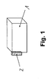
- Fig. 1 shows a schematic view of an energy storage, the storage enclosure 1 is associated with a volume compensation device 2.
- Fig. 2 shows a schematic view of an energy storage device, wherein the volume compensation device 2 is arranged outside of the storage housing 1.
- Fig. 3 shows a schematic view of an energy storage device, wherein the volume compensation device 2 is disposed within the storage enclosure 1.
- Fig. 4 shows a schematic view of an energy storage device, wherein the volume compensation device 2 from the storage housing 1 by a tube 3 or a pipe 4, not shown, is arranged at a distance.
- Fig. 5 shows a schematic view of a volume compensation device 2, which has a piston 5.
- the piston 5 is received in a piston housing 6 and therefore movable in two dimensions.
- Fig. 6 shows a schematic view of a volume compensation device 2, which has a balloon 7.
- the balloon 7 is located in a balloon housing 8 and is in this in three dimensions expansion capable. It is also conceivable that the balloon 7 is used without balloon housing 8.
- Fig. 7 shows a schematic view of a volume compensation device 2, which has a rolling diaphragm 9.
- the rolling diaphragm 9 is located in a rolling diaphragm housing 10 and is movable in two dimensions.
- Fig. 8 shows a schematic view of a volume compensation device 2, which has a bellows 11, wherein in the upper view of the compressed and in the lower view of the expanded bellows 11 is shown.
- Fig. 9 shows a schematic view of a volume compensation device 2, which has a membrane 12 in a membrane housing 13 in the manner of a rechargeable battery or bladder accumulator.
- Fig. 10 shows a schematic view of a volume compensation device 2, which is disposed within a storage housing 1 and a bellows 11, wherein between the environment and the interior of the bellows 11, a filter element 14 is arranged.
- the bellows 11 is located in the interior of the storage housing 1.
- the compensating volume 15 of the bellows 11 is protected from penetrating particles. It is also conceivable to operate the bellows 11 without filter element 14.
- Fig. 11 shows a schematic view of a volume compensation device 2, which is disposed within a storage housing 1 and having a bellows 11 which is compressed.
- Fig. 12 shows a schematic view of a valve 16 for reducing an overpressure.
- the valve 16 has a spring-loaded valve piston 17 which can release or close an outlet 18.
- the valve piston 17 is loaded by the spring 19.
- Fig. 13 shows a schematic view of the valve 16 according to Fig. 12 , It is shown how a fluid escapes from the interior of the storage case 1, not shown.
- Fig. 14 shows a schematic view of the valve 16 according to Fig. 12 in which it is shown how a fluid escapes from the interior of the storage housing into an absorber element 20.
- Fig. 15 shows a schematic view of a volume compensation device 2, which has a bellows 11 with a rupture disk 21.
- Fig. 16 shows a schematic view of a volume compensation device 2, which has a rolling diaphragm 9 with a rupture disk 21.
- Fig. 17 shows a schematic view of a volume compensation device 2, which has a movable housing cover 22, wherein between the housing cover 22 and the storage housing 1, a frame seal 23 is arranged.
- Fig. 18 shows a schematic view of a volume compensation device 2, which has a movable housing cover 22, wherein between the housing cover 22 and the storage housing 1 a bellows-like seal 24 is arranged, which protrudes into the interior of the storage enclosure 1 or in the vicinity of the storage enclosure 1, in Fig. 18 schematically both embodiments of the Abragens are shown.
- the energy store described in the figures is preferably configured as a battery, in particular as a motor vehicle battery.
- the storage housing 1 is preferably designed as a battery case.
Abstract
Description
Die Erfindung betrifft einen Energiespeicher mit einem Speichergehäuse, welches ein Volumen einschließt, in welchem Zellen aufgenommen sind, wobei das Speichergehäuse das Volumen gegen die Umgebung abschirmt.The invention relates to an energy storage device with a storage housing which encloses a volume in which cells are accommodated, wherein the storage housing shields the volume from the environment.
In großen Batteriegehäusen befinden sich Zellen, die in sich hermetisch abgeschirmt sind. Diese Zellen werden in der Regel durch Kontaktkühlung gekühlt. Dabei ist die Temperatur innerhalb des Batteriegehäuses kleiner als die Temperatur außerhalb des Batteriegehäuses. Die Kontaktkühlung umfasst entweder drucklose Systeme, die wasserbasierte Medien, wie Wasser-Glykol-Mischungen, enthalten, oder echte Kimaanlagen, die mit Fluorkohlenwasserstoffen oder Kohlendioxid arbeiten.Large battery cases contain cells that are hermetically sealed. These cells are usually cooled by contact cooling. The temperature inside the battery case is smaller than the temperature outside the battery case. Contact cooling includes either pressureless systems containing water-based media, such as water-glycol mixtures, or real air conditioners that use fluorocarbons or carbon dioxide.
Typische Volumina von Batterien, die in Hybrid- und Elektrofahrzeugen verwendet werden, betragen mehr als 50 l (l=Liter). Batterien von Elektrofahrzeugen weisen sogar Volumina auf, die größer als 100 l sind.Typical volumes of batteries used in hybrid and electric vehicles are more than 50 l (l = liter). Electric vehicle batteries even have volumes greater than 100 liters.
Vor diesem Hintergrund befindet sich in einem Batteriegehäuse üblicherweise ein unvermeidbares Totvolumen von ca. 5% des gesamten Volumens der Batterie. Je nach Ausführungsform der Zellen kann dieses Totvolumen aber auch wesentlich größer sein. Insbesondere geometrisch ungünstige Rundzellen erlauben eine nur relativ geringe Raumnutzung.Against this background, a battery housing usually contains an unavoidable dead volume of approximately 5% of the total volume of the battery. Depending on the embodiment of the cells, this dead volume can also be substantially larger. In particular geometrically unfavorable round cells allow only a relatively small use of space.
In einem hermetisch, insbesondere isochor, abgeschlossenen Batteriegehäuse können aufgrund von Druckschwankungen, die durch Temperaturschwankungen hervorgerufen werden, sowohl leichte Über- als auch Unterdrücke entstehen. Diese sind insbesondere für die Abdichtung der in der Batterie angebrachten Zellen kritisch und beeinflussen die Lebensdauer des gesamten Batterie-Systems.In a hermetically, in particular isochorally, closed battery housing, due to pressure fluctuations, which are caused by temperature fluctuations, both slight excess and negative pressures occur. These are particularly critical for sealing the cells mounted in the battery and affect the life of the entire battery system.
Darüber hinaus können größere Druckschwankungen negative Einflüsse auf weitere Batteriekomponenten, insbesondere die elektrische Leistungs- und Überwachungs-Kontaktierung der Zellen sowie die Abdichtungen der Gehäusedurchführungen von Kabeln nehmen.In addition, larger pressure fluctuations can negatively affect other battery components, especially the electrical power and monitoring contacting of the cells, as well as the seals of the housing feedthroughs of cables.
In einer derzeit praktizierten Ausführung [
Die genannte Ausführung ist zwar bei relativ kleinen Batterien, wie "Mild-Hybrid-Batterien", noch umsetzbar, bei großen Batterien, wie sie für reine Elektrofahrzeuge verwendet werden, entstehen allerdings nicht mehr betriebstaugliche Massen und Kosten.Although the said design is still feasible for relatively small batteries, such as "mild hybrid batteries", in large batteries, as used for pure electric vehicles, however, no longer masses and costs that are no longer suitable for operation.
Falls das Totvolumen nicht mit festen bzw. flüssigen Substanzen aufgefüllt wird und die Batterie insbesondere nicht hermetisch abgedichtet ist, kann durch Temperaturschwankungen ein stofflicher Volumenaustausch mit der Umgebung erfolgen. Beim Abkühlen der Batterie kann diese Luft einsaugen. Hierbei können sowohl Feuchtigkeit als auch Staub ins Innere der Batterie gelangen. Die Feuchtigkeit kann im Inneren der Batterie kondensieren. Dies ist besonders kritisch, da Wasseranreicherungen zu Kurzschlüssen und Korrosion führen können.If the dead volume is not filled up with solid or liquid substances and in particular the battery is not hermetically sealed, temperature fluctuations can cause a material volume exchange with the environment. When cooling the battery, this air can suck in. Both moisture and dust can get inside the battery. The moisture can condense inside the battery. This is particularly critical because water accumulation can cause short circuits and corrosion.
Diese ausgetauschten Luftvolumina sind gering. Bei einem Temperaturunterschied von 50 K und einem Volumen von 5 l beträgt das ausgetauschte Luftvolumen 50/300 * 5 l, also etwa 1 l. Die dabei auftretenden Luftströme sind sehr niedrig, betragen nämlich ca. 1 l/h.These exchanged air volumes are low. At a temperature difference of 50 K and a volume of 5 l, the exchanged air volume is 50/300 * 5 l, ie about 1 l. The occurring air currents are very low, namely about 1 l / h.
Eine weitere Anforderung an Batterie-Systeme besteht dahingehend, dass im Notfall freigesetzte brennbare Gase entweder sicher im Batteriegehäuse verbleiben oder sicher und gezielt abgeleitet bzw. abgebunden werden. Derzeitige Ausführungen machen von einem diffusionsoffenen Druckausgleichselement im Batteriegehäuse gebrauch. Ein Druckausgleichselement erlaubt einen stofflichen Austausch zwischen dem Inneren der Batterie und der Umgebung. Derzeit werden hier vor allem mikroporöse Membranen, beispielsweise aus "Gore-Tex", verwendet, da sie neben einem stofflichen Austausch auch das Eindringen von Partikeln und flüssigem Wasser wirkungsvoll verhindern. Bei einer solchen Ausführung kann allerdings Wasser im gasförmigen Zustand ins Innere des Batteriegehäuses gelangen und dort kondensieren. Das kondensierte Wasser kann dann nicht mehr durch die mikroporöse Membran nach außen gelangen und sammelt sich folglich im Inneren des Gehäuses.Another requirement of battery systems is that flammable gases released in an emergency either remain safely in the battery housing or are safely and selectively discharged or set. Present designs make use of a vapor-open pressure compensation element in the battery housing. A pressure compensation element allows a material exchange between the interior of the battery and the environment. At present, especially microporous membranes, for example from "Gore-Tex", are used because they effectively prevent the penetration of particles and liquid water in addition to a material exchange. In such an embodiment, however, water in the gaseous state can reach the inside of the battery case and condense there. The condensed water can then no longer pass through the microporous membrane to the outside and thus accumulates inside the housing.
Auch dies birgt die Gefahr von Korrosion an den elektrischen Kontakten sowie von Kurzschlüssen der Leistungs-Elektronik. Beides hat einen Totalausfall der Batterie zur Folge.This also carries the risk of corrosion on the electrical contacts and short circuits of the power electronics. Both result in a total failure of the battery.
Das genannte Problem gestaltet sich umso schlimmer, wenn zusätzlich zu dem Kondenswasser gasförmige salzbildende Substanzen ins Innere der Batterie gelangen. Beispielsweise reagiert Chlorwasserstoff (HCl) mit dem kondensierten Wasser zu Salzsäure, welche extrem korrosiv wirkt. Hier kann es zu Lochfraßkorrosion kommen. Des Weiteren wird die elektrische Leitfähigkeit des Wassers drastisch erhöht, was wiederum das Risiko von elektrischen Kurzschlüssen erhöht.The above problem is all the worse if, in addition to the condensation, gaseous salt-forming substances reach the inside of the battery. For example, hydrogen chloride (HCl) reacts with the condensed water to form hydrochloric acid, which is extremely corrosive. This can lead to pitting corrosion. Furthermore, the electrical conductivity of the water is drastically increased, which in turn increases the risk of electrical short circuits.
Eine verbesserte Ausführung macht vom Anbringen von Filtern bzw. Filter- und Entfeuchterelementen gebrauch. Durch diese Maßnahme kann auch Wasser im gasförmigen Zustand abgefangen und/ oder abgebunden werden. Das Wasser kann so nicht ins Innere der Batterie gelangen.An improved design makes use of attaching filters or filter and dehumidifier elements. By this measure can also water be intercepted in the gaseous state and / or tied off. The water can not get inside the battery.
Bei diesen Ausführungen ist nachteilig, dass sie das Innere des Batteriegehäuses nicht dauerhaft abschließen. Die Wasser-Abbinde-Kapazität ist nach einer gewissen Zeit erschöpft. Das Entfeuchterelement ist daher je nach Luftfeuchte und Einsatzdauer ein auszutauschendes Verschleißbauteil. Des Weiteren muss absolut sicher gestellt werden, dass das Entfeuchterelement nicht mit Wasser kontaminiert wird, welches von außen ansteht. Dieses Wasser kann bei Auto-Batterien als Watwasser, bei Auto-Batterien bei Hochdruckreinigem oder bei Waschanlagen auftreten.In these embodiments, it is disadvantageous that they do not permanently close the interior of the battery housing. The water-setting capacity is exhausted after a certain time. The dehumidifying element is therefore an exchangeable wear component, depending on the humidity and duration of use. Furthermore, it must be absolutely certain that the dehumidifier element is not contaminated with water that is present from the outside. This water can occur in car batteries as wading water, in auto batteries in high-pressure cleaners or car washes.
Der Erfindung liegt daher die Aufgabe zu Grunde, einen Energiespeicher anzugeben, bei dem ein problemloser Druckausgleich bei dauerhaft hoher Dichtheit gewährleistet ist.The invention is therefore based on the object to provide an energy storage, in which a trouble-free pressure equalization is ensured at permanently high density.
Erfindungsgemäß wird die voranstehende Aufgabe durch einen Energiespeicher mit den Merkmalen des Patentanspruchs 1 gelöst.According to the invention the above object is achieved by an energy storage with the features of
Danach ist der eingangs genannte Energiespeicher dadurch gekennzeichnet, dass dem Speichergehäuse eine Volumenkompensationseinrichtung zugeordnet ist, welche Druckdifferenzen zwischen dem Inneren des Speichergehäuses und der Umgebung ausgleicht, ohne dass ein stofflicher Austausch zwischen Umgebung und Innerem des Speichergehäuses stattfindet.Thereafter, the above-mentioned energy storage is characterized in that the storage enclosure is associated with a volume compensation device, which compensates for pressure differences between the interior of the storage enclosure and the environment, without a material exchange between the environment and the interior of the storage enclosure takes place.
Erfindungsgemäß kompensiert die Volumenkompensationseinrichtung typische Druckschwankungen, die durch Temperaturänderungen hervorgerufen werden. Danach findet erfindungsgemäß zwischen dem Inneren des Speichergehäuses und der Umgebung unter normalen Arbeitsbedingungen kein Stoffaustausch statt. Die Druckdifferenzen zwischen dem Inneren und der äußeren Umgebung des Speichergehäuses, welche durch Temperaturschwankungen hervorgerufen werden, werden erfindungsgemäß weitestgehend kompensiert. Die Zellen innerhalb des Speichergehäuses erfahren erfindungsgemäß keine mechanische Belastung durch wesentlich unterschiedliche Druckdifferenzen, die zwischen einem hermetisch abgeschlossenen, isochoren Inneren des Speichergehäuses und dessen Umgebung herrschen würden. Des Weiteren wird das Innere des Speichergehäuses dauerhaft abgedichtet, da kein stofflicher Austausch zwischen dem Inneren des Speichergehäuses und dessen Umgebung stattfindet.According to the invention, the volume compensation device compensates for typical pressure fluctuations caused by temperature changes. Thereafter, according to the invention, no mass transfer takes place between the interior of the storage housing and the environment under normal working conditions. The pressure differences between the interior and the outer environment of the storage housing, which are caused by temperature fluctuations are inventively compensated as far as possible. According to the invention, the cells within the storage housing experience no mechanical load due to substantially different pressure differences which would prevail between a hermetically sealed, isochoric interior of the storage housing and its surroundings. Furthermore, the interior of the storage enclosure is permanently sealed because there is no material exchange between the interior of the storage enclosure and its surroundings.
Folglich ist die eingangs genannte Aufgabe gelöst.Consequently, the object mentioned above is achieved.
Die Volumenkompensationseinrichtung könnte innerhalb des Speichergehäuses angeordnet sein. Hierbei kann eine Ausgleichsmöglichkeit in zwei Dimensionen realisiert werden. Die konkrete Ausgestaltung bewirkt vorteilhaft, dass die Volumenkompensationseinrichtung durch das feste Speichergehäuse geschützt ist. Des Weiteren wird vorteilhaft Totvolumen im Energiespeicher, insbesondere in einer Batterie, genutzt.The volume compensation device could be located within the storage enclosure. In this case, a compensation possibility can be realized in two dimensions. The specific embodiment advantageously has the effect that the volume compensation device is protected by the fixed storage housing. Furthermore, it is advantageous to use dead volumes in the energy store, in particular in a battery.
Die Volumenkompensationseinrichtung könnte außerhalb am Speichergehäuse angeordnet sein. Hierdurch kann die Volumenkompensationseinrichtung problemlos auf Schäden überprüft werden.The volume compensation device could be arranged outside on the storage housing. As a result, the volume compensation device can be easily checked for damage.
Die Volumenkompensationseinrichtung könnte außerhalb des Speichergehäuses von diesem beabstandet angeordnet sein. Bei dieser konkreten Ausgestaltung könnte die Volumenkompensationseinrichtung durch einen Schlauch oder ein Rohr mit dem Speichergehäuse stofflich verbunden sein. Diese Anordnung ist vorteilhaft, wenn in der unmittelbaren Umgebung des Speichergehäuses nicht genügend Raum zur Verfügung steht bzw. andere freie Räume eingebunden werden können. Zudem können Vorteile entstehen, wenn eine später noch näher ausgeführte Berstfunktion integriert werden soll. Durch Trennung der Volumenkompensationseinrichtung vom Speichergehäuse kann entstehendes, brennbares bzw. toxisches Gas vom Energiespeicher, insbesondere einer Batterie, entfernt werden, von heißen Teilen ferngehalten werden oder ggf. sogar aus der Fahrgastzelle eines Kraftfahrzeugs entfernt werden.The volume compensation device could be arranged outside of the storage housing spaced therefrom. In this specific embodiment, the volume compensation device could be materially connected by a hose or a pipe with the storage housing. This arrangement is advantageous if in the immediate vicinity of the storage enclosure is not enough space available or other free spaces can be involved. In addition, advantages can arise if a bursting function that will be explained in more detail later is to be integrated. By separating the volume compensation device from the storage housing emerging, flammable or toxic gas from the energy storage, in particular a battery can be removed, kept away from hot parts or possibly even removed from the passenger compartment of a motor vehicle.
Es könnte eine Volumenkompensationseinrichtung vorgesehen sein, die einen flexiblen Teil aufweist, der ein Volumen umgibt, in welches und/ oder aus welchem Luft zur Kompensation von Temperaturschwankungen bereitgestellt werden kann.A volume compensation device could be provided which has a flexible part surrounding a volume into which and / or from which air can be made available to compensate for temperature fluctuations.
Vor diesem Hintergrund könnte die Volumenkompensationseinrichtung einen ausdehnungsfähigen Ballon aufweisen. Hierdurch ist eine Volumenkompensation in drei Dimensionen ermöglicht. Der Ballon könnte in einer starren Aufnahme aufgenommen sein. Hierdurch ist eine platzsparende Volumenkompensation in zwei Dimensionen möglich. Vor diesem Hintergrund könnte der Ballon mit einem Kolben oder einer Rollmembran zusammenwirken.Against this background, the volume compensation device could have an expandable balloon. This allows volume compensation in three dimensions. The balloon could be included in a rigid shot. This allows space-saving volume compensation in two dimensions. Against this background, the balloon could interact with a piston or a rolling diaphragm.
Die Volumenkompensationseinrichtung könnte einen ausdehnungsfähigen Faltenbalg aufweisen. Ein Faltenbalg kann in zwei Dimensionen bewegt, sowie sehr flach und damit platzsparend zusammengelegt werden.The volume compensation device could comprise an expansible bellows. A bellows can be moved in two dimensions, as well as being very flat and thus saving space.
Die Volumenkompensationseinrichtung könnte eine Rollmembran aufweisen. Rollmembranen können sehr gut an Wandungen geführt werden.The volume compensation device could comprise a rolling diaphragm. Rolling membranes can be guided very well on walls.
Die Volumenkompensationseinrichtung könnte einen Blasenspeicher aufweisen. Diese konkrete Ausgestaltung realisiert eine Ausgleichsmöglichkeit in drei Dimensionen, wobei vorzugsweise eine Ausgleichsmöglichkeit in einer oder auch zwei Dimensionen beschritten werden kann.The volume compensation device could comprise a bladder accumulator. This concrete embodiment realizes a compensation possibility in three dimensions, wherein preferably a compensation possibility can be taken in one or two dimensions.
Vor diesem Hintergrund könnte die Volumenkompensationseinrichtung einen Akkumulator aufweisen. Dieser kann sehr hohe Druckdifferenzen ausgleichen.Against this background, the volume compensation device could comprise an accumulator. This can compensate for very high pressure differences.
Die Volumenkompensationseinrichtung könnte einen beweglichen Gehäusedeckel aufweisen. Hierdurch ist ein kompakter und teilearmer Aufbau der Batterie sicher gestellt, da der Gehäusedeckel ein ohnehin vorhandenes Bauteil darstellt Der Gehäusedeckel ist vorteilhaft beweglich und durch eine umlaufende Dichtung an dem Speichergehäuse fluiddicht angeordnet. Eine Druckänderung führt zu einem Anheben oder Absenken des Gehäusedeckels. Diese konkrete Ausgestaltung ist besonders vorteilhaft, da aufgrund der regelmäßig großen Fläche des Speichergehäuses bzw. des Gehäusedeckels für einen Druckausgleich nur relativ geringe Verschiebehöhen des Gehäusedeckels notwendig werden. Vor diesem Hintergrund kann die umlaufende Dichtung mit einem O-förmigen Querschnitt versehen, aber auch profiliert ausgestaltet sein.The volume compensation device could have a movable housing cover. As a result, a compact and low-part construction of the battery is ensured because the housing cover is an already existing component The housing cover is advantageously movable and arranged fluid-tight by a peripheral seal on the storage housing. A pressure change leads to a raising or lowering of the housing cover. This specific embodiment is particularly advantageous because only relatively small displacement heights of the housing cover are necessary due to the regularly large surface of the storage enclosure or the housing cover for pressure equalization. Against this background, the circumferential seal can be provided with an O-shaped cross section, but also profiled designed.
Vor diesem Hintergrund könnte der Gehäusedeckel eine umlaufende, balgartige Dichtung aufweisen, wobei die Dichtung ins Innere des Speichergehäuses oder in die Umgebung des Speichergehäuses abragt. Der Gehäusedeckel kann hierdurch ohne großen mechanischen Widerstand bewegt werden. Die balgartige Dichtung ist vorteilhaft als umlaufende Faltendichtung ausgestaltet. Diese führt sowohl im druckbelasteten, abgesenkten als auch im druckentlasteten, angehobenen Zustand zu einer stofflichen Abdichtung. Die Faltendichtung kann dabei entweder nach außen gerichtet abragen oder nach innen gerichtet abragen.Against this background, the housing cover could have a circumferential, bellows-like seal, wherein the seal protrudes into the interior of the storage housing or in the vicinity of the storage housing. The housing cover can thereby without much mechanical resistance to be moved. The bellows-like seal is advantageously designed as a circumferential fold seal. This leads to a material seal both in the pressure-loaded, lowered and in the pressure-relieved raised state. The folding seal can either protrude directed outward or protrude inwards.
Die Volumenkompensationseinrichtung könnte ein Filterelement aufweisen. Hierdurch ist sichergestellt, dass nahezu keine Partikel in ein veränderliches Ausgleichsvolumen, insbesondere eines Faltenbalgs, eintreten.The volume compensation device could comprise a filter element. This ensures that almost no particles in a variable compensating volume, in particular a bellows, enter.
Die Volumenkompensationseinrichtung könnte ein Absorberelement aufweisen. In einem Absorberelement können schädigende Gase aufgenommen werden.The volume compensation device could comprise an absorber element. In an absorber element harmful gases can be absorbed.
Die Volumenkompensationseinrichtung könnte ein Ventil aufweisen. Bei einem Störfall können im Energiespeicher, insbesondere in einer Batterie, gasförmige Substanzen frei werden. Diese Substanzen umfassen abgeblasene Elektrolyten oder Zersetzungsprodukte. Die pro schadhafte Zelle freigesetzten Volumina gasförmiger Substanzen betragen typischerweise mehr als 5 l. Diese Volumina werden in relativ kurzen Zeiten, nämlich in weniger als einer Minute, freigesetzt. Dies führt dann zu einer abnormen Druckerhöhung innerhalb des Speichergehäuses. Je nach vorhandenem Totvolumen kann das Speichergehäuse mechanisch so ausgelegt werden, dass es die dabei entstehenden Überdrücke noch toleriert. Eine solche Auslegung wäre allerdings schwer und würde spätestens beim Versagen mehrerer Zellen versagen. Es würde dann zu einem unkontrollierten Abblasen kommen. Unter Umständen kann es sogar zu einer Explosion kommen. Das hier beschriebene Ventil löst bei normalen, relativ kleinen Druckdifferenzen zwischen dem Inneren des Speichergehäuses und dessen Umgebung noch nicht aus. Bei abnormen größeren Druckdifferenzen werden Gase im Inneren der Batterie sicher abgeleitet.The volume compensation device could comprise a valve. In the event of an accident, gaseous substances can be released in the energy store, in particular in a battery. These substances include blown-off electrolytes or decomposition products. The volumes of gaseous substances released per defective cell are typically more than 5 liters. These volumes are released in relatively short times, less than a minute. This then leads to an abnormal pressure increase within the storage enclosure. Depending on the existing dead volume, the storage housing can be mechanically designed so that it still tolerates the resulting pressures. However, such an interpretation would be difficult and would fail at the latest in the failure of multiple cells. It would then come to an uncontrolled blow-off. It may even cause an explosion. The valve described here does not trigger at normal, relatively small pressure differences between the interior of the storage enclosure and its environment. In case of abnormal pressure differences, gases are safely discharged inside the battery.
Das Ventil könnte einen Ventilkolben aufweisen. Der Ventilkolben kann vorteilhaft mit einer Feder verbunden sein und bei größeren Drücken im Inneren des Speichergehäuses einen Ausgang reversibel freigeben, durch den der Überdruck entweichen kann. Die Ableitung der ggf. brennbaren und toxischen Gase dann durch einen Schlauch oder ein Rohr erfolgen.The valve could have a valve piston. The valve piston can advantageously be connected to a spring and at higher pressures in the interior of the storage housing, an output reversibly release, through which the pressure can escape. The discharge of any flammable and toxic gases then take place through a hose or a pipe.
Das Ventil könnte eine Berstscheibe aufweisen oder als Berstscheibe ausgestaltet sein. Eine Berstscheibe öffnet vorteilhaft bei einem definierten Druck im Inneren des Speichergehäuses und leitet schnell Gas von innen nach außen ab. Die Berstscheibe kann mit einem Schlauch oder einem Filterelement kombiniert werden.The valve could have a rupture disk or be configured as a rupture disk. A rupture disc opens advantageous at a defined pressure in the interior of the storage enclosure and quickly diverts gas from the inside out. The rupture disc can be combined with a hose or a filter element.
Das Ventil könnte ein Absorberelement aufweisen. In einem Absorberelement können schädigende Gase aufgenommen werden. Vor diesem Hintergrund könnten die entweichenden Gase in einem speziellen Absorberelement, insbesondere in einem Filterelement oder einer porösen Schüttung, aufgenommen werden. Hierdurch wird die Umgebung vor den entweichenden Gasen weitgehend geschont.The valve could have an absorber element. In an absorber element harmful gases can be absorbed. Against this background, the escaping gases could be absorbed in a special absorber element, in particular in a filter element or a porous bed. As a result, the environment is largely protected from the escaping gases.
Die Rollmembran, der Faltenbalg, der Blasenspeicher, der Kolben, der Akkumulator oder die balgartige Dichtung könnten aus Elastomeren gefertigt sein. Dieser Werkstoff verleiht den genannten Bauteilen eine geeignete Elastizität.The rolling diaphragm, the bellows, the bladder accumulator, the piston, the accumulator or the bellows-type seal could be made of elastomers. This material gives the components mentioned a suitable elasticity.
Der hier beschriebene elektrochemische Energiespeicher kann als Batterie oder als Superkondensator ausgestaltet sein. Auch hier sind die einzelnen Kondensator-Zellen in einem großen Gehäuse untergebracht und unterliegen derselben eingangs genannten Problematik.The electrochemical energy store described here can be designed as a battery or as a supercapacitor. Again, the individual capacitor cells are housed in a large housing and are subject to the same problem mentioned above.
Es gibt nun verschiedene Möglichkeiten, die Lehre der vorliegenden Erfindung auf vorteilhafte Weise auszugestalten und weiterzubilden. Dazu ist einerseits auf die nachgeordneten Ansprüche, andererseits auf die nachfolgende Erläuterung bevorzugter Ausführungsbeispiele der Erfindung anhand der Zeichnung zu verweisen.There are now various possibilities for embodying and developing the teaching of the present invention in an advantageous manner. For this purpose, on the one hand to the subordinate claims, on the other hand, to refer to the following explanation of preferred embodiments of the invention with reference to the drawings.
In Verbindung mit der Erläuterung der bevorzugten Ausführungsbeispiele der Erfindung anhand der Zeichnung werden auch im Allgemeinen bevorzugte Ausgestaltungen und Weiterbildungen der Lehre erläutert.In conjunction with the explanation of the preferred embodiments of the invention with reference to the drawings, also generally preferred embodiments and developments of the teaching are explained.
- Fig. 1Fig. 1
- eine schematische Ansicht eines Energiespeichers, dessen Speichergehäuse eine Volumenkompensationseinrichtung zugeordnet ist,a schematic view of an energy storage, the storage enclosure is associated with a volume compensation device,
- Fig. 2Fig. 2
- eine schematische Ansicht eines Energiespeichers, wobei eine Valumenkompensationseinrichtung außerhalb des Speichergehäuses angeordnet ist,a schematic view of an energy store, wherein a Valumenkompensationseinrichtung is disposed outside the storage enclosure,
- Fig. 3Fig. 3
- eine schematische Ansicht eines Energiespeichers, wobei eine Volumenkompensationseinrichtung innerhalb des Speichergehäuses angeordnet ist,a schematic view of an energy storage, wherein a volume compensation device is disposed within the storage enclosure,
- Fig. 4Fig. 4
- eine schematische Ansicht eines Energiespeichers, wobei eine Volumenkompensationseinrichtung vom Speichergehäuse durch einen Schlauch oder ein Rohr beabstandet angeordnet ist,a schematic view of an energy storage device, wherein a volume compensation device from the storage housing is arranged by a tube or a tube spaced
- Fig. 5Fig. 5
- eine schematische Ansicht einer Volumenkompensationseinrichtung, die einen Kolben aufweist,a schematic view of a volume compensation device having a piston,
- Fig. 6Fig. 6
- eine schematische Ansicht einer Volumenkompensationseinrichtung, die einen Ballon aufweist,a schematic view of a volume compensation device having a balloon,
- Fig. 7Fig. 7
- eine schematische Ansicht einer Volumenkompensationseinrichtung, die eine Rollmembran aufweist,a schematic view of a volume compensation device having a rolling diaphragm,
- Fig. 8Fig. 8
- eine schematische Ansicht einer Volumenkompensationseinrichtung, die einen Faltenbalg aufweist, wobei in der oberen Ansicht der komprimierte und in der unteren Ansicht der expandierte Faltenbalg gezeigt ist,a schematic view of a volume compensation device having a bellows, wherein in the upper view of the compressed and shown in the lower view of the expanded bellows,
- Fig. 9Fig. 9
- eine schematische Ansicht einer Volumenkompensationseinrichtung, die eine Membran in einem Gehäuse nach Art eines Akkumulators oder Blasenspeichers aufweist,a schematic view of a volume compensation device having a membrane in a housing in the manner of an accumulator or bladder accumulator,
- Fig. 10Fig. 10
- eine schematische Ansicht einer Volumenkompensationseinrichtung, die innerhalb eines Speichergehäuses angeordnet ist und einen Faltenbalg aufweist, wobei zwischen Umgebung und innerem des Faltenbalgs optional ein Filterelement angeordnet ist,a schematic view of a volume compensation device which is disposed within a storage housing and having a bellows, wherein between the environment and the inner of the bellows optionally a filter element is arranged,
- Fig. 11Fig. 11
-
eine schematische Ansicht der in
Fig. 10 dargestellten Volumenkompensationseinrichtung, die innerhalb einesa schematic view of inFig. 10 Volume compensation device shown within a - Fig. 12Fig. 12
- Speichergehäuses angeordnet ist und einen Faltenbalg bei erhöhten Innendrücken aufweist, eine schematische Ansicht eines Ventils zum Abbau eines Überdrucks,Storage housing is arranged and having a bellows at elevated internal pressures, a schematic view of a valve for reducing an overpressure,
- Fig. 13Fig. 13
-
eine schematische Ansicht des Ventils gemäß
Fig. 12 , wobei dargestellt ist, wie ein Fluid aus dem Inneren des Speichergehäuses entweicht,a schematic view of the valve according toFig. 12 showing how a fluid escapes from the interior of the storage enclosure, - Fig. 14Fig. 14
-
eine schematische Ansicht des Ventils gemäß
Fig. 12 , wobei dargestellt ist, wie ein Fluid aus dem Inneren des Speichergehäuses in ein Absorberelement entweicht,a schematic view of the valve according toFig. 12 showing how a fluid escapes from the interior of the storage housing into an absorber element, - Fig. 15Fig. 15
- eine schematische Ansicht einer Volumenkompensationseinrichtung, die einen Faltenbalg mit einer Berstscheibe aufweist,a schematic view of a volume compensation device having a bellows with a rupture disc,
- Fig. 16Fig. 16
- eine schematische Ansicht einer Volumenkompensationseinrichtung, die eine Rollmembran mit einer Berstscheibe aufweist,a schematic view of a volume compensation device having a rolling diaphragm with a bursting disc,
- Fig. 17Fig. 17
- eine schematische Ansicht einer Volumenkompensationseinrichtung, die einen beweglichen Gehäusedeckel aufweist, wobei zwischen Gehäusedeckel und Speichergehäuse als Rahmendichtung eine O-Ringdichtung angeordnet ist, unda schematic view of a volume compensation device having a movable housing cover, wherein between the housing cover and the storage housing as a frame seal an O-ring seal is arranged, and
- Fig. 18Fig. 18
- eine schematische Ansicht einer Volumenkompensationseinrichtung, die einen beweglichen Gehäusedeckel aufweist, wobei zwischen Gehäusedeckel und Speichergehäuse eine balgartige Dichtung angeordnet ist, welche ins Innere des Speichergehäuses oder in die Umgebung des Speichergehäuses abragt.a schematic view of a volume compensation device, a movable Housing cover, wherein between the housing cover and storage housing, a bellows-like seal is arranged, which protrudes into the interior of the storage enclosure or in the environment of the storage enclosure.
Der in den Figuren beschriebene Energiespeicher ist bevorzugt als Batterie, insbesondere als Kraftfahrzeugbatterie, ausgestaltet. Das Speichergehäuse 1 ist bevorzugt als Batteriegehäuse ausgestaltet.The energy store described in the figures is preferably configured as a battery, in particular as a motor vehicle battery. The
Hinsichtlich weiterer vorteilhafter Ausgestaltungen und Weiterbildungen der erfindungsgemäßen Lehre wird einerseits auf den allgemeinen Teil der Beschreibung und andererseits auf die beigefügten Patentansprüche verwiesen.With regard to further advantageous embodiments and developments of the teaching of the invention reference is made on the one hand to the general part of the description and on the other hand to the appended claims.
Abschließend sei ganz besonders hervorgehoben, dass die zuvor gewählten Ausführungsbeispiele lediglich zur Erörterung der erfindungsgemäßen Lehre dienen, diese jedoch nicht auf diese Ausführungsbeispiele einschränken.Finally, it should be particularly emphasized that the previously selected embodiments are merely for the purpose of discussion of the teaching of the invention, but not limit these to these embodiments.
Claims (18)
Priority Applications (4)
| Application Number | Priority Date | Filing Date | Title |
|---|---|---|---|
| EP09010805A EP2290729B1 (en) | 2009-08-24 | 2009-08-24 | Electric storage device with a volume compensation unit |
| US12/855,252 US8647758B2 (en) | 2009-08-24 | 2010-08-12 | Electrochemical energy storage device |
| BRPI1004252-0A BRPI1004252A2 (en) | 2009-08-24 | 2010-08-23 | electrochemical energy storage device |
| CA2713613A CA2713613C (en) | 2009-08-24 | 2010-08-24 | Electrochemical energy storage device |
Applications Claiming Priority (1)
| Application Number | Priority Date | Filing Date | Title |
|---|---|---|---|
| EP09010805A EP2290729B1 (en) | 2009-08-24 | 2009-08-24 | Electric storage device with a volume compensation unit |
Publications (2)
| Publication Number | Publication Date |
|---|---|
| EP2290729A1 true EP2290729A1 (en) | 2011-03-02 |
| EP2290729B1 EP2290729B1 (en) | 2012-10-10 |
Family
ID=41076727
Family Applications (1)
| Application Number | Title | Priority Date | Filing Date |
|---|---|---|---|
| EP09010805A Active EP2290729B1 (en) | 2009-08-24 | 2009-08-24 | Electric storage device with a volume compensation unit |
Country Status (4)
| Country | Link |
|---|---|
| US (1) | US8647758B2 (en) |
| EP (1) | EP2290729B1 (en) |
| BR (1) | BRPI1004252A2 (en) |
| CA (1) | CA2713613C (en) |
Cited By (12)
| Publication number | Priority date | Publication date | Assignee | Title |
|---|---|---|---|---|
| EP2533346A1 (en) * | 2011-06-09 | 2012-12-12 | Carl Freudenberg KG | Device for removing liquids from an energy storage device |
| WO2013121027A1 (en) * | 2012-02-16 | 2013-08-22 | Rheinisch-Westfälische Technische Hochschule Aachen | Energy storage apparatus comprising at least one storage cell and method for volume compensation of electrode materials of such a storage cell |
| DE102013009212A1 (en) * | 2013-05-31 | 2014-12-04 | Volkswagen Aktiengesellschaft | Pressure equalization device for a closed volume |
| DE102013222630A1 (en) * | 2013-11-07 | 2015-05-07 | Volkswagen Ag | Energy storage and / or energy converter |
| DE102013020910A1 (en) | 2013-12-12 | 2015-06-18 | Daimler Ag | Battery for a vehicle and vehicle |
| DE102015208912A1 (en) * | 2015-05-13 | 2016-11-17 | Novero Gmbh | Device for storing electrical energy, method for operating such a device and method for producing such a device |
| WO2019105674A1 (en) | 2017-12-01 | 2019-06-06 | Bayerische Motoren Werke Aktiengesellschaft | Storage housing for a high-voltage accumulaor of a motor vehicle, high-voltage accumulator, and motor vehicle |
| DE102018128816A1 (en) * | 2018-11-16 | 2020-05-20 | Volkswagen Aktiengesellschaft | Modular battery |
| DE102020003906A1 (en) * | 2020-06-29 | 2021-04-01 | Daimler Ag | Cooling device for an electrical energy storage device, as well as battery arrangement and method |
| DE102020101679A1 (en) | 2020-01-24 | 2021-07-29 | Bayerische Motoren Werke Aktiengesellschaft | Battery housing for a traction battery with a discharge device, traction battery and motor vehicle |
| DE102016115645B4 (en) | 2016-08-23 | 2022-08-25 | Kirchhoff Automotive Deutschland Gmbh | battery case |
| DE102016016012B3 (en) | 2016-08-23 | 2023-02-02 | Kirchhoff Automotive Deutschland Gmbh | battery case |
Families Citing this family (11)
| Publication number | Priority date | Publication date | Assignee | Title |
|---|---|---|---|---|
| DE102010041131A1 (en) * | 2010-09-21 | 2012-03-22 | Robert Bosch Gmbh | Element for controlling the internal gas pressure in Li-ion cells |
| US8592063B1 (en) * | 2012-05-29 | 2013-11-26 | Vecture, Inc. | Battery pack pressure valve |
| JP6308366B2 (en) * | 2014-07-25 | 2018-04-11 | 住友電気工業株式会社 | Electrolyte circulating battery |
| EP3018728A1 (en) * | 2014-11-05 | 2016-05-11 | Sandvik Mining and Construction Oy | Pressure equalization device, vehicle and system |
| US10522800B2 (en) | 2015-01-30 | 2019-12-31 | Ford Global Technologies, Llc | Variable volume battery assembly |
| DE102017214242A1 (en) | 2017-08-16 | 2019-02-21 | Robert Bosch Gmbh | Battery cell, battery module and method of making such |
| KR102324549B1 (en) * | 2017-08-29 | 2021-11-10 | 주식회사 엘지에너지솔루션 | Pouch-Type Secondary Battery Having Venting Guidance Device |
| DE102020104893A1 (en) | 2020-02-25 | 2021-08-26 | Bayerische Motoren Werke Aktiengesellschaft | Receiving device, in particular housing, for receiving at least one energy storage device, in particular for a motor vehicle |
| JP2023540668A (en) * | 2020-07-10 | 2023-09-26 | ポラリウム・エナジー・ソリューションズ・エービー | Battery devices containing flame-retardant encapsulants |
| DE102021103378B3 (en) * | 2021-02-12 | 2022-01-20 | Bayerische Motoren Werke Aktiengesellschaft | Traction battery with degassing collector and motor vehicle |
| US20220328912A1 (en) * | 2021-04-09 | 2022-10-13 | Brunswick Corporation | Watertight Marine Battery |
Citations (7)
| Publication number | Priority date | Publication date | Assignee | Title |
|---|---|---|---|---|
| DE1421216A1 (en) * | 1955-04-28 | 1968-10-03 | P J Moll | Battery, especially long motorcycle battery |
| US3514341A (en) * | 1968-05-31 | 1970-05-26 | Eagle Picher Ind Inc | Battery cell case with pressure equalizer |
| DE2310403A1 (en) * | 1973-03-02 | 1974-09-12 | Bosch Gmbh Robert | OVERCHARGE PROTECTION DEVICE FOR MAINTENANCE-FREE ACCUMULATORS |
| DE4210431C1 (en) * | 1992-03-30 | 1993-04-15 | Deta-Akkumulatorenwerk Gmbh, 3422 Bad Lauterberg, De | Pole bolt penetration for accumulators - has elastic sealant joined to housing lid and tensioned between pole-nut and-bolt |
| JPH0917401A (en) * | 1995-06-28 | 1997-01-17 | Japan Storage Battery Co Ltd | Organic electrolytic solution battery |
| DE102007017018A1 (en) * | 2007-04-11 | 2008-03-27 | Daimler Ag | Battery e.g. lithium ion battery, for fuel cell-vehicle, has bypass device designed such that contact unit is switched to switching condition, in which defective cell is by-passed for maintaining current path of battery, if cell is failed |
| WO2008120056A1 (en) * | 2007-03-30 | 2008-10-09 | Toyota Jidosha Kabushiki Kaisha | Electricity storage device and vehicle including the same |
Family Cites Families (22)
| Publication number | Priority date | Publication date | Assignee | Title |
|---|---|---|---|---|
| US2457800A (en) * | 1944-10-16 | 1949-01-04 | Joseph W Allen | Self-sealing vent cap |
| US2743035A (en) * | 1952-10-09 | 1956-04-24 | Charles F Fogarty | Explosion proof battery enclosure |
| US3285784A (en) * | 1964-11-05 | 1966-11-15 | Bell Telephone Labor Inc | Nickel-cadmium battery receptacle |
| US3673001A (en) * | 1970-06-29 | 1972-06-27 | Sperry Rand Corp | Control means for a rechargeable battery |
| US4517261A (en) * | 1983-07-01 | 1985-05-14 | Energy Development Associates, Inc. | Hydrogen gas relief valve |
| DE69115078T2 (en) * | 1990-02-15 | 1996-05-09 | Japan Storage Battery Co Ltd | Closed lead acid battery. |
| US5538807A (en) * | 1992-09-03 | 1996-07-23 | Nikon Corporation | Vent valve for an amphibious equipment having a battery housing |
| AU7099494A (en) * | 1993-06-10 | 1995-01-03 | Derafe, Ltd. | Bipolar lead/acid batteries |
| DE69733186T2 (en) * | 1996-07-09 | 2005-11-17 | Matsushita Electric Industrial Co., Ltd., Kadoma | SECONDARY CELL WITH SEALANT PLATE |
| US5876872A (en) * | 1996-11-08 | 1999-03-02 | Feezor; Michael D. | Underwater rechargeable battery and method of manufacture |
| US7041412B2 (en) * | 2001-07-23 | 2006-05-09 | Matsushita Electric Industrial Co., Ltd. | Non-aqueous electrolyte secondary battery |
| US20030113615A1 (en) * | 2001-12-13 | 2003-06-19 | Gerd Tomazic | Recombinator for the re-acidification of an electrolyte stream in a flowing electrolyte zinc-bromine battery |
| JP5011664B2 (en) * | 2005-07-11 | 2012-08-29 | パナソニック株式会社 | Sealed secondary battery |
| EP1987554A1 (en) * | 2006-02-17 | 2008-11-05 | Nilar International AB | A bipolar battery including a pressure sensor |
| JP5147206B2 (en) * | 2006-08-11 | 2013-02-20 | 三洋電機株式会社 | Nonaqueous electrolyte secondary battery |
| JP5172315B2 (en) * | 2007-12-18 | 2013-03-27 | プライムアースEvエナジー株式会社 | Secondary battery |
| US20120021260A1 (en) * | 2010-01-29 | 2012-01-26 | Panasonic Corporation | Battery module |
| CN101901886B (en) * | 2010-07-15 | 2013-06-12 | 东莞新能源电子科技有限公司 | Power battery explosion protection device |
| KR101191657B1 (en) * | 2010-07-19 | 2012-10-17 | 에스비리모티브 주식회사 | Battery module |
| US8980480B2 (en) * | 2011-07-20 | 2015-03-17 | Spectrum Brands, Inc. | Lithium primary cell |
| JP5788815B2 (en) * | 2012-01-27 | 2015-10-07 | 三洋電機株式会社 | Prismatic secondary battery |
| JP5888730B2 (en) * | 2012-01-27 | 2016-03-22 | 三洋電機株式会社 | Prismatic secondary battery |
-
2009
- 2009-08-24 EP EP09010805A patent/EP2290729B1/en active Active
-
2010
- 2010-08-12 US US12/855,252 patent/US8647758B2/en active Active
- 2010-08-23 BR BRPI1004252-0A patent/BRPI1004252A2/en not_active Application Discontinuation
- 2010-08-24 CA CA2713613A patent/CA2713613C/en not_active Expired - Fee Related
Patent Citations (7)
| Publication number | Priority date | Publication date | Assignee | Title |
|---|---|---|---|---|
| DE1421216A1 (en) * | 1955-04-28 | 1968-10-03 | P J Moll | Battery, especially long motorcycle battery |
| US3514341A (en) * | 1968-05-31 | 1970-05-26 | Eagle Picher Ind Inc | Battery cell case with pressure equalizer |
| DE2310403A1 (en) * | 1973-03-02 | 1974-09-12 | Bosch Gmbh Robert | OVERCHARGE PROTECTION DEVICE FOR MAINTENANCE-FREE ACCUMULATORS |
| DE4210431C1 (en) * | 1992-03-30 | 1993-04-15 | Deta-Akkumulatorenwerk Gmbh, 3422 Bad Lauterberg, De | Pole bolt penetration for accumulators - has elastic sealant joined to housing lid and tensioned between pole-nut and-bolt |
| JPH0917401A (en) * | 1995-06-28 | 1997-01-17 | Japan Storage Battery Co Ltd | Organic electrolytic solution battery |
| WO2008120056A1 (en) * | 2007-03-30 | 2008-10-09 | Toyota Jidosha Kabushiki Kaisha | Electricity storage device and vehicle including the same |
| DE102007017018A1 (en) * | 2007-04-11 | 2008-03-27 | Daimler Ag | Battery e.g. lithium ion battery, for fuel cell-vehicle, has bypass device designed such that contact unit is switched to switching condition, in which defective cell is by-passed for maintaining current path of battery, if cell is failed |
Non-Patent Citations (1)
| Title |
|---|
| LAMM ET AL.: "Lithium-tonen-Batterie. Erster Serieneinsatz im S400 Hybrid", ATZ, vol. 111, 2009, pages 490 |
Cited By (14)
| Publication number | Priority date | Publication date | Assignee | Title |
|---|---|---|---|---|
| EP2533346A1 (en) * | 2011-06-09 | 2012-12-12 | Carl Freudenberg KG | Device for removing liquids from an energy storage device |
| WO2013121027A1 (en) * | 2012-02-16 | 2013-08-22 | Rheinisch-Westfälische Technische Hochschule Aachen | Energy storage apparatus comprising at least one storage cell and method for volume compensation of electrode materials of such a storage cell |
| DE102013009212A1 (en) * | 2013-05-31 | 2014-12-04 | Volkswagen Aktiengesellschaft | Pressure equalization device for a closed volume |
| DE102013222630A1 (en) * | 2013-11-07 | 2015-05-07 | Volkswagen Ag | Energy storage and / or energy converter |
| DE102013020910A1 (en) | 2013-12-12 | 2015-06-18 | Daimler Ag | Battery for a vehicle and vehicle |
| DE102015208912A1 (en) * | 2015-05-13 | 2016-11-17 | Novero Gmbh | Device for storing electrical energy, method for operating such a device and method for producing such a device |
| DE102016115645B4 (en) | 2016-08-23 | 2022-08-25 | Kirchhoff Automotive Deutschland Gmbh | battery case |
| DE102016016012B3 (en) | 2016-08-23 | 2023-02-02 | Kirchhoff Automotive Deutschland Gmbh | battery case |
| WO2019105674A1 (en) | 2017-12-01 | 2019-06-06 | Bayerische Motoren Werke Aktiengesellschaft | Storage housing for a high-voltage accumulaor of a motor vehicle, high-voltage accumulator, and motor vehicle |
| DE102017221622A1 (en) | 2017-12-01 | 2019-06-06 | Bayerische Motoren Werke Aktiengesellschaft | Storage housing for a high-voltage accumulator of a motor vehicle, high-voltage storage and motor vehicle |
| DE102018128816A1 (en) * | 2018-11-16 | 2020-05-20 | Volkswagen Aktiengesellschaft | Modular battery |
| DE102018128816B4 (en) | 2018-11-16 | 2022-09-29 | Volkswagen Aktiengesellschaft | Modular battery |
| DE102020101679A1 (en) | 2020-01-24 | 2021-07-29 | Bayerische Motoren Werke Aktiengesellschaft | Battery housing for a traction battery with a discharge device, traction battery and motor vehicle |
| DE102020003906A1 (en) * | 2020-06-29 | 2021-04-01 | Daimler Ag | Cooling device for an electrical energy storage device, as well as battery arrangement and method |
Also Published As
| Publication number | Publication date |
|---|---|
| US8647758B2 (en) | 2014-02-11 |
| US20110045324A1 (en) | 2011-02-24 |
| CA2713613C (en) | 2013-01-22 |
| CA2713613A1 (en) | 2011-02-24 |
| EP2290729B1 (en) | 2012-10-10 |
| BRPI1004252A2 (en) | 2012-05-15 |
Similar Documents
| Publication | Publication Date | Title |
|---|---|---|
| EP2290729B1 (en) | Electric storage device with a volume compensation unit | |
| EP2325937B1 (en) | Plug-in piece | |
| DE102007010740B4 (en) | Battery with ventilation and use of the battery | |
| DE102014217425A1 (en) | Clamping device for battery cells and battery module, battery, battery system, vehicle and method for producing a battery module | |
| DE102009000660A1 (en) | battery module | |
| DE102012202103A1 (en) | Pressure compensation element with a membrane, housing, battery cell module and motor vehicle | |
| EP2385274A1 (en) | Profile seal with corner connectors | |
| DE102008052284A1 (en) | Electrical battery e.g. lithium-ion battery, for use in vehicle with hybrid drive, has sealing element at which predetermined breaking point is provided, where selective releasing of opening takes place in point during faulty condition | |
| EP2980882B1 (en) | Frame for electrochemical cells | |
| DE102011103998A1 (en) | Energy storage unit and / or converter unit | |
| WO2013110359A1 (en) | Battery and motor vehicle | |
| DE102013213877A1 (en) | Battery system comprising at least one battery cell and a battery case | |
| EP2418708B1 (en) | Closure element for battery casing | |
| DE102012211827A1 (en) | Battery housing for accommodating cell of lithium ion battery for e.g. passenger car, has closure element releasing opening of battery housing wall by inner pressure in housing for realizing volume flow from housing | |
| DE102013223361A1 (en) | Battery cell with safety valve and semi-permeable closure element | |
| DE102013210154B4 (en) | Device for increasing safety when using battery systems | |
| DE102009058955A1 (en) | Volume compensation arrangement for cooling- or heating medium of battery, has flexible housing on which prestressed elastic element acts or has rigid housing which is arranged to another flexible housing | |
| DE102019102459A1 (en) | Battery with overpressure hose seal | |
| WO2022117262A1 (en) | Degassing unit assembly, degassing unit, use of a degassing unit in a degassing assembly, and battery housing | |
| DE102010051000A1 (en) | Battery for use in hybrid vehicle or electric vehicle, has battery housing whose interior is sealed hermetically, filled with dry gas and fluidically connected with expansion vessel in which piston is mounted | |
| DE102019122033A1 (en) | Drying device and drying system | |
| EP2118946A1 (en) | Electrochemical cell comprising an electrode pack and a connecting element for a used air evacuation duct | |
| WO2008037763A1 (en) | Energy storage module | |
| DE102013203106A1 (en) | Housing for battery cell e.g. lithium ion battery cell, has gastight and fluid-conductive connected channel portions that are arranged for forming degassing channel, and safety valve that is opened into channel portion | |
| DE102013022632B3 (en) | Device for increasing safety when using battery systems |
Legal Events
| Date | Code | Title | Description |
|---|---|---|---|
| PUAI | Public reference made under article 153(3) epc to a published international application that has entered the european phase |
Free format text: ORIGINAL CODE: 0009012 |
|
| AK | Designated contracting states |
Kind code of ref document: A1 Designated state(s): AT BE BG CH CY CZ DE DK EE ES FI FR GB GR HR HU IE IS IT LI LT LU LV MC MK MT NL NO PL PT RO SE SI SK SM TR |
|
| AX | Request for extension of the european patent |
Extension state: AL BA RS |
|
| 17P | Request for examination filed |
Effective date: 20110830 |
|
| 17Q | First examination report despatched |
Effective date: 20110927 |
|
| GRAP | Despatch of communication of intention to grant a patent |
Free format text: ORIGINAL CODE: EPIDOSNIGR1 |
|
| RIC1 | Information provided on ipc code assigned before grant |
Ipc: H01M 10/42 20060101ALI20120216BHEP Ipc: H01M 2/10 20060101AFI20120216BHEP Ipc: H01M 6/50 20060101ALN20120216BHEP Ipc: H01M 2/12 20060101ALN20120216BHEP |
|
| GRAS | Grant fee paid |
Free format text: ORIGINAL CODE: EPIDOSNIGR3 |
|
| GRAA | (expected) grant |
Free format text: ORIGINAL CODE: 0009210 |
|
| AK | Designated contracting states |
Kind code of ref document: B1 Designated state(s): AT BE BG CH CY CZ DE DK EE ES FI FR GB GR HR HU IE IS IT LI LT LU LV MC MK MT NL NO PL PT RO SE SI SK SM TR |
|
| REG | Reference to a national code |
Ref country code: GB Ref legal event code: FG4D Free format text: NOT ENGLISH |
|
| REG | Reference to a national code |
Ref country code: AT Ref legal event code: REF Ref document number: 579311 Country of ref document: AT Kind code of ref document: T Effective date: 20121015 Ref country code: CH Ref legal event code: EP |
|
| REG | Reference to a national code |
Ref country code: IE Ref legal event code: FG4D Free format text: LANGUAGE OF EP DOCUMENT: GERMAN |
|
| REG | Reference to a national code |
Ref country code: DE Ref legal event code: R096 Ref document number: 502009005015 Country of ref document: DE Effective date: 20121129 |
|
| PG25 | Lapsed in a contracting state [announced via postgrant information from national office to epo] |
Ref country code: SI Free format text: LAPSE BECAUSE OF FAILURE TO SUBMIT A TRANSLATION OF THE DESCRIPTION OR TO PAY THE FEE WITHIN THE PRESCRIBED TIME-LIMIT Effective date: 20121010 |
|
| REG | Reference to a national code |
Ref country code: NL Ref legal event code: VDEP Effective date: 20121010 |
|
| REG | Reference to a national code |
Ref country code: LT Ref legal event code: MG4D |
|
| PG25 | Lapsed in a contracting state [announced via postgrant information from national office to epo] |
Ref country code: SE Free format text: LAPSE BECAUSE OF FAILURE TO SUBMIT A TRANSLATION OF THE DESCRIPTION OR TO PAY THE FEE WITHIN THE PRESCRIBED TIME-LIMIT Effective date: 20121010 Ref country code: LT Free format text: LAPSE BECAUSE OF FAILURE TO SUBMIT A TRANSLATION OF THE DESCRIPTION OR TO PAY THE FEE WITHIN THE PRESCRIBED TIME-LIMIT Effective date: 20121010 Ref country code: HR Free format text: LAPSE BECAUSE OF FAILURE TO SUBMIT A TRANSLATION OF THE DESCRIPTION OR TO PAY THE FEE WITHIN THE PRESCRIBED TIME-LIMIT Effective date: 20121010 Ref country code: FI Free format text: LAPSE BECAUSE OF FAILURE TO SUBMIT A TRANSLATION OF THE DESCRIPTION OR TO PAY THE FEE WITHIN THE PRESCRIBED TIME-LIMIT Effective date: 20121010 Ref country code: IS Free format text: LAPSE BECAUSE OF FAILURE TO SUBMIT A TRANSLATION OF THE DESCRIPTION OR TO PAY THE FEE WITHIN THE PRESCRIBED TIME-LIMIT Effective date: 20130210 Ref country code: ES Free format text: LAPSE BECAUSE OF FAILURE TO SUBMIT A TRANSLATION OF THE DESCRIPTION OR TO PAY THE FEE WITHIN THE PRESCRIBED TIME-LIMIT Effective date: 20130121 Ref country code: NL Free format text: LAPSE BECAUSE OF FAILURE TO SUBMIT A TRANSLATION OF THE DESCRIPTION OR TO PAY THE FEE WITHIN THE PRESCRIBED TIME-LIMIT Effective date: 20121010 Ref country code: NO Free format text: LAPSE BECAUSE OF FAILURE TO SUBMIT A TRANSLATION OF THE DESCRIPTION OR TO PAY THE FEE WITHIN THE PRESCRIBED TIME-LIMIT Effective date: 20130110 |
|
| PG25 | Lapsed in a contracting state [announced via postgrant information from national office to epo] |
Ref country code: PT Free format text: LAPSE BECAUSE OF FAILURE TO SUBMIT A TRANSLATION OF THE DESCRIPTION OR TO PAY THE FEE WITHIN THE PRESCRIBED TIME-LIMIT Effective date: 20130211 Ref country code: LV Free format text: LAPSE BECAUSE OF FAILURE TO SUBMIT A TRANSLATION OF THE DESCRIPTION OR TO PAY THE FEE WITHIN THE PRESCRIBED TIME-LIMIT Effective date: 20121010 Ref country code: PL Free format text: LAPSE BECAUSE OF FAILURE TO SUBMIT A TRANSLATION OF THE DESCRIPTION OR TO PAY THE FEE WITHIN THE PRESCRIBED TIME-LIMIT Effective date: 20121010 Ref country code: GR Free format text: LAPSE BECAUSE OF FAILURE TO SUBMIT A TRANSLATION OF THE DESCRIPTION OR TO PAY THE FEE WITHIN THE PRESCRIBED TIME-LIMIT Effective date: 20130111 |
|
| PG25 | Lapsed in a contracting state [announced via postgrant information from national office to epo] |
Ref country code: BG Free format text: LAPSE BECAUSE OF FAILURE TO SUBMIT A TRANSLATION OF THE DESCRIPTION OR TO PAY THE FEE WITHIN THE PRESCRIBED TIME-LIMIT Effective date: 20130110 Ref country code: EE Free format text: LAPSE BECAUSE OF FAILURE TO SUBMIT A TRANSLATION OF THE DESCRIPTION OR TO PAY THE FEE WITHIN THE PRESCRIBED TIME-LIMIT Effective date: 20121010 Ref country code: SK Free format text: LAPSE BECAUSE OF FAILURE TO SUBMIT A TRANSLATION OF THE DESCRIPTION OR TO PAY THE FEE WITHIN THE PRESCRIBED TIME-LIMIT Effective date: 20121010 Ref country code: CZ Free format text: LAPSE BECAUSE OF FAILURE TO SUBMIT A TRANSLATION OF THE DESCRIPTION OR TO PAY THE FEE WITHIN THE PRESCRIBED TIME-LIMIT Effective date: 20121010 Ref country code: DK Free format text: LAPSE BECAUSE OF FAILURE TO SUBMIT A TRANSLATION OF THE DESCRIPTION OR TO PAY THE FEE WITHIN THE PRESCRIBED TIME-LIMIT Effective date: 20121010 |
|
| PLBE | No opposition filed within time limit |
Free format text: ORIGINAL CODE: 0009261 |
|
| STAA | Information on the status of an ep patent application or granted ep patent |
Free format text: STATUS: NO OPPOSITION FILED WITHIN TIME LIMIT |
|
| PG25 | Lapsed in a contracting state [announced via postgrant information from national office to epo] |
Ref country code: RO Free format text: LAPSE BECAUSE OF FAILURE TO SUBMIT A TRANSLATION OF THE DESCRIPTION OR TO PAY THE FEE WITHIN THE PRESCRIBED TIME-LIMIT Effective date: 20121010 Ref country code: IT Free format text: LAPSE BECAUSE OF FAILURE TO SUBMIT A TRANSLATION OF THE DESCRIPTION OR TO PAY THE FEE WITHIN THE PRESCRIBED TIME-LIMIT Effective date: 20121010 |
|
| 26N | No opposition filed |
Effective date: 20130711 |
|
| REG | Reference to a national code |
Ref country code: DE Ref legal event code: R097 Ref document number: 502009005015 Country of ref document: DE Effective date: 20130711 |
|
| PG25 | Lapsed in a contracting state [announced via postgrant information from national office to epo] |
Ref country code: CY Free format text: LAPSE BECAUSE OF FAILURE TO SUBMIT A TRANSLATION OF THE DESCRIPTION OR TO PAY THE FEE WITHIN THE PRESCRIBED TIME-LIMIT Effective date: 20121010 |
|
| BERE | Be: lapsed |
Owner name: CARL FREUDENBERG K.G. Effective date: 20130831 |
|
| REG | Reference to a national code |
Ref country code: CH Ref legal event code: PL |
|
| GBPC | Gb: european patent ceased through non-payment of renewal fee |
Effective date: 20130824 |
|
| PG25 | Lapsed in a contracting state [announced via postgrant information from national office to epo] |
Ref country code: CH Free format text: LAPSE BECAUSE OF NON-PAYMENT OF DUE FEES Effective date: 20130831 Ref country code: MC Free format text: LAPSE BECAUSE OF FAILURE TO SUBMIT A TRANSLATION OF THE DESCRIPTION OR TO PAY THE FEE WITHIN THE PRESCRIBED TIME-LIMIT Effective date: 20121010 Ref country code: LI Free format text: LAPSE BECAUSE OF NON-PAYMENT OF DUE FEES Effective date: 20130831 |
|
| REG | Reference to a national code |
Ref country code: IE Ref legal event code: MM4A |
|
| PG25 | Lapsed in a contracting state [announced via postgrant information from national office to epo] |
Ref country code: BE Free format text: LAPSE BECAUSE OF NON-PAYMENT OF DUE FEES Effective date: 20130831 |
|
| PG25 | Lapsed in a contracting state [announced via postgrant information from national office to epo] |
Ref country code: IE Free format text: LAPSE BECAUSE OF NON-PAYMENT OF DUE FEES Effective date: 20130824 Ref country code: GB Free format text: LAPSE BECAUSE OF NON-PAYMENT OF DUE FEES Effective date: 20130824 |
|
| PG25 | Lapsed in a contracting state [announced via postgrant information from national office to epo] |
Ref country code: SM Free format text: LAPSE BECAUSE OF FAILURE TO SUBMIT A TRANSLATION OF THE DESCRIPTION OR TO PAY THE FEE WITHIN THE PRESCRIBED TIME-LIMIT Effective date: 20121010 |
|
| PG25 | Lapsed in a contracting state [announced via postgrant information from national office to epo] |
Ref country code: MT Free format text: LAPSE BECAUSE OF FAILURE TO SUBMIT A TRANSLATION OF THE DESCRIPTION OR TO PAY THE FEE WITHIN THE PRESCRIBED TIME-LIMIT Effective date: 20121010 Ref country code: TR Free format text: LAPSE BECAUSE OF FAILURE TO SUBMIT A TRANSLATION OF THE DESCRIPTION OR TO PAY THE FEE WITHIN THE PRESCRIBED TIME-LIMIT Effective date: 20121010 |
|
| PG25 | Lapsed in a contracting state [announced via postgrant information from national office to epo] |
Ref country code: MK Free format text: LAPSE BECAUSE OF FAILURE TO SUBMIT A TRANSLATION OF THE DESCRIPTION OR TO PAY THE FEE WITHIN THE PRESCRIBED TIME-LIMIT Effective date: 20121010 Ref country code: HU Free format text: LAPSE BECAUSE OF FAILURE TO SUBMIT A TRANSLATION OF THE DESCRIPTION OR TO PAY THE FEE WITHIN THE PRESCRIBED TIME-LIMIT; INVALID AB INITIO Effective date: 20090824 Ref country code: LU Free format text: LAPSE BECAUSE OF NON-PAYMENT OF DUE FEES Effective date: 20130824 |
|
| REG | Reference to a national code |
Ref country code: FR Ref legal event code: PLFP Year of fee payment: 7 |
|
| REG | Reference to a national code |
Ref country code: AT Ref legal event code: MM01 Ref document number: 579311 Country of ref document: AT Kind code of ref document: T Effective date: 20140824 |
|
| PG25 | Lapsed in a contracting state [announced via postgrant information from national office to epo] |
Ref country code: AT Free format text: LAPSE BECAUSE OF NON-PAYMENT OF DUE FEES Effective date: 20140824 |
|
| REG | Reference to a national code |
Ref country code: FR Ref legal event code: PLFP Year of fee payment: 8 |
|
| REG | Reference to a national code |
Ref country code: FR Ref legal event code: PLFP Year of fee payment: 9 |
|
| REG | Reference to a national code |
Ref country code: FR Ref legal event code: PLFP Year of fee payment: 10 |
|
| REG | Reference to a national code |
Ref country code: DE Ref legal event code: R079 Ref document number: 502009005015 Country of ref document: DE Free format text: PREVIOUS MAIN CLASS: H01M0002100000 Ipc: H01M0050200000 |
|
| PGFP | Annual fee paid to national office [announced via postgrant information from national office to epo] |
Ref country code: FR Payment date: 20230824 Year of fee payment: 15 Ref country code: DE Payment date: 20230831 Year of fee payment: 15 |