JP6308366B2 - Electrolyte circulating battery - Google Patents
Electrolyte circulating battery Download PDFInfo
- Publication number
- JP6308366B2 JP6308366B2 JP2014152431A JP2014152431A JP6308366B2 JP 6308366 B2 JP6308366 B2 JP 6308366B2 JP 2014152431 A JP2014152431 A JP 2014152431A JP 2014152431 A JP2014152431 A JP 2014152431A JP 6308366 B2 JP6308366 B2 JP 6308366B2
- Authority
- JP
- Japan
- Prior art keywords
- pressure
- gas
- bag
- gas phase
- tank
- Prior art date
- Legal status (The legal status is an assumption and is not a legal conclusion. Google has not performed a legal analysis and makes no representation as to the accuracy of the status listed.)
- Active
Links
- 239000003792 electrolyte Substances 0.000 title claims description 58
- 239000007789 gas Substances 0.000 claims description 259
- 239000012071 phase Substances 0.000 claims description 117
- 230000007246 mechanism Effects 0.000 claims description 66
- QVGXLLKOCUKJST-UHFFFAOYSA-N atomic oxygen Chemical compound [O] QVGXLLKOCUKJST-UHFFFAOYSA-N 0.000 claims description 29
- 239000001301 oxygen Substances 0.000 claims description 29
- 229910052760 oxygen Inorganic materials 0.000 claims description 29
- 239000008151 electrolyte solution Substances 0.000 claims description 26
- 239000011261 inert gas Substances 0.000 claims description 16
- 230000033228 biological regulation Effects 0.000 claims description 14
- 230000004888 barrier function Effects 0.000 claims description 10
- 239000007792 gaseous phase Substances 0.000 claims description 9
- 230000008859 change Effects 0.000 claims description 3
- 239000002648 laminated material Substances 0.000 claims description 2
- 239000010410 layer Substances 0.000 description 35
- 239000000463 material Substances 0.000 description 23
- 229920005989 resin Polymers 0.000 description 13
- 239000011347 resin Substances 0.000 description 13
- 230000001629 suppression Effects 0.000 description 12
- 239000004698 Polyethylene Substances 0.000 description 11
- 239000007788 liquid Substances 0.000 description 11
- 229920000573 polyethylene Polymers 0.000 description 11
- QAOWNCQODCNURD-UHFFFAOYSA-N Sulfuric acid Chemical compound OS(O)(=O)=O QAOWNCQODCNURD-UHFFFAOYSA-N 0.000 description 10
- XLYOFNOQVPJJNP-UHFFFAOYSA-N water Substances O XLYOFNOQVPJJNP-UHFFFAOYSA-N 0.000 description 10
- 238000010248 power generation Methods 0.000 description 9
- IJGRMHOSHXDMSA-UHFFFAOYSA-N Atomic nitrogen Chemical compound N#N IJGRMHOSHXDMSA-UHFFFAOYSA-N 0.000 description 8
- 230000000903 blocking effect Effects 0.000 description 8
- 238000009434 installation Methods 0.000 description 7
- 238000004891 communication Methods 0.000 description 6
- 230000007423 decrease Effects 0.000 description 6
- 238000007599 discharging Methods 0.000 description 6
- -1 hydrogen ions Chemical class 0.000 description 6
- 238000007254 oxidation reaction Methods 0.000 description 6
- 239000000470 constituent Substances 0.000 description 5
- 239000003595 mist Substances 0.000 description 5
- 230000003647 oxidation Effects 0.000 description 5
- 230000035699 permeability Effects 0.000 description 5
- 239000004800 polyvinyl chloride Substances 0.000 description 5
- 239000000956 alloy Substances 0.000 description 4
- 229910045601 alloy Inorganic materials 0.000 description 4
- 238000010586 diagram Methods 0.000 description 4
- 230000004048 modification Effects 0.000 description 4
- 238000012986 modification Methods 0.000 description 4
- 229910052757 nitrogen Inorganic materials 0.000 description 4
- 230000029058 respiratory gaseous exchange Effects 0.000 description 4
- 238000012790 confirmation Methods 0.000 description 3
- 230000008602 contraction Effects 0.000 description 3
- 230000007797 corrosion Effects 0.000 description 3
- 238000005260 corrosion Methods 0.000 description 3
- 230000006866 deterioration Effects 0.000 description 3
- 230000000694 effects Effects 0.000 description 3
- 150000002500 ions Chemical class 0.000 description 3
- 229920001684 low density polyethylene Polymers 0.000 description 3
- 239000004702 low-density polyethylene Substances 0.000 description 3
- 229920000915 polyvinyl chloride Polymers 0.000 description 3
- 239000011241 protective layer Substances 0.000 description 3
- 230000001105 regulatory effect Effects 0.000 description 3
- 239000007787 solid Substances 0.000 description 3
- 230000000007 visual effect Effects 0.000 description 3
- XKRFYHLGVUSROY-UHFFFAOYSA-N Argon Chemical compound [Ar] XKRFYHLGVUSROY-UHFFFAOYSA-N 0.000 description 2
- CURLTUGMZLYLDI-UHFFFAOYSA-N Carbon dioxide Chemical compound O=C=O CURLTUGMZLYLDI-UHFFFAOYSA-N 0.000 description 2
- 229920000219 Ethylene vinyl alcohol Polymers 0.000 description 2
- XEEYBQQBJWHFJM-UHFFFAOYSA-N Iron Chemical compound [Fe] XEEYBQQBJWHFJM-UHFFFAOYSA-N 0.000 description 2
- 239000004952 Polyamide Substances 0.000 description 2
- 239000004743 Polypropylene Substances 0.000 description 2
- 239000007864 aqueous solution Substances 0.000 description 2
- 239000001257 hydrogen Substances 0.000 description 2
- 229910052739 hydrogen Inorganic materials 0.000 description 2
- 239000012535 impurity Substances 0.000 description 2
- 229910010272 inorganic material Inorganic materials 0.000 description 2
- 239000011147 inorganic material Substances 0.000 description 2
- 239000007769 metal material Substances 0.000 description 2
- 239000011368 organic material Substances 0.000 description 2
- 229920002647 polyamide Polymers 0.000 description 2
- 229920001155 polypropylene Polymers 0.000 description 2
- 229920001343 polytetrafluoroethylene Polymers 0.000 description 2
- 239000004810 polytetrafluoroethylene Substances 0.000 description 2
- 239000002356 single layer Substances 0.000 description 2
- 239000000243 solution Substances 0.000 description 2
- OKTJSMMVPCPJKN-UHFFFAOYSA-N Carbon Chemical compound [C] OKTJSMMVPCPJKN-UHFFFAOYSA-N 0.000 description 1
- UGFAIRIUMAVXCW-UHFFFAOYSA-N Carbon monoxide Chemical compound [O+]#[C-] UGFAIRIUMAVXCW-UHFFFAOYSA-N 0.000 description 1
- RYGMFSIKBFXOCR-UHFFFAOYSA-N Copper Chemical compound [Cu] RYGMFSIKBFXOCR-UHFFFAOYSA-N 0.000 description 1
- RWSOTUBLDIXVET-UHFFFAOYSA-N Dihydrogen sulfide Chemical compound S RWSOTUBLDIXVET-UHFFFAOYSA-N 0.000 description 1
- 239000004593 Epoxy Substances 0.000 description 1
- FYYHWMGAXLPEAU-UHFFFAOYSA-N Magnesium Chemical compound [Mg] FYYHWMGAXLPEAU-UHFFFAOYSA-N 0.000 description 1
- 229920002292 Nylon 6 Polymers 0.000 description 1
- 239000004372 Polyvinyl alcohol Substances 0.000 description 1
- 229920001328 Polyvinylidene chloride Polymers 0.000 description 1
- 239000002253 acid Substances 0.000 description 1
- 239000003513 alkali Substances 0.000 description 1
- 229910052782 aluminium Inorganic materials 0.000 description 1
- XAGFODPZIPBFFR-UHFFFAOYSA-N aluminium Chemical compound [Al] XAGFODPZIPBFFR-UHFFFAOYSA-N 0.000 description 1
- 229910052786 argon Inorganic materials 0.000 description 1
- DQXBYHZEEUGOBF-UHFFFAOYSA-N but-3-enoic acid;ethene Chemical compound C=C.OC(=O)CC=C DQXBYHZEEUGOBF-UHFFFAOYSA-N 0.000 description 1
- 229910052799 carbon Inorganic materials 0.000 description 1
- 229910002092 carbon dioxide Inorganic materials 0.000 description 1
- 239000001569 carbon dioxide Substances 0.000 description 1
- 229910002091 carbon monoxide Inorganic materials 0.000 description 1
- 239000010949 copper Substances 0.000 description 1
- 229910052802 copper Inorganic materials 0.000 description 1
- 238000005536 corrosion prevention Methods 0.000 description 1
- 239000005038 ethylene vinyl acetate Substances 0.000 description 1
- 239000012530 fluid Substances 0.000 description 1
- 150000002431 hydrogen Chemical class 0.000 description 1
- 229910000037 hydrogen sulfide Inorganic materials 0.000 description 1
- 229910052742 iron Inorganic materials 0.000 description 1
- 239000011777 magnesium Substances 0.000 description 1
- 229910052749 magnesium Inorganic materials 0.000 description 1
- 238000012423 maintenance Methods 0.000 description 1
- 238000005259 measurement Methods 0.000 description 1
- 229910052754 neon Inorganic materials 0.000 description 1
- GKAOGPIIYCISHV-UHFFFAOYSA-N neon atom Chemical compound [Ne] GKAOGPIIYCISHV-UHFFFAOYSA-N 0.000 description 1
- 229910052756 noble gas Inorganic materials 0.000 description 1
- 150000002835 noble gases Chemical class 0.000 description 1
- 230000033116 oxidation-reduction process Effects 0.000 description 1
- 229920001200 poly(ethylene-vinyl acetate) Polymers 0.000 description 1
- 229920002451 polyvinyl alcohol Polymers 0.000 description 1
- 239000005033 polyvinylidene chloride Substances 0.000 description 1
- 229920005604 random copolymer Polymers 0.000 description 1
- 238000006722 reduction reaction Methods 0.000 description 1
- 239000011342 resin composition Substances 0.000 description 1
- 238000007789 sealing Methods 0.000 description 1
- 239000002904 solvent Substances 0.000 description 1
- 230000006641 stabilisation Effects 0.000 description 1
- 238000011105 stabilization Methods 0.000 description 1
- 239000010935 stainless steel Substances 0.000 description 1
- 229910001220 stainless steel Inorganic materials 0.000 description 1
- 229910001456 vanadium ion Inorganic materials 0.000 description 1
- 239000012808 vapor phase Substances 0.000 description 1
Images


Classifications
-
- H—ELECTRICITY
- H01—ELECTRIC ELEMENTS
- H01M—PROCESSES OR MEANS, e.g. BATTERIES, FOR THE DIRECT CONVERSION OF CHEMICAL ENERGY INTO ELECTRICAL ENERGY
- H01M8/00—Fuel cells; Manufacture thereof
- H01M8/04—Auxiliary arrangements, e.g. for control of pressure or for circulation of fluids
- H01M8/04082—Arrangements for control of reactant parameters, e.g. pressure or concentration
- H01M8/04201—Reactant storage and supply, e.g. means for feeding, pipes
-
- H—ELECTRICITY
- H01—ELECTRIC ELEMENTS
- H01M—PROCESSES OR MEANS, e.g. BATTERIES, FOR THE DIRECT CONVERSION OF CHEMICAL ENERGY INTO ELECTRICAL ENERGY
- H01M8/00—Fuel cells; Manufacture thereof
- H01M8/04—Auxiliary arrangements, e.g. for control of pressure or for circulation of fluids
-
- H—ELECTRICITY
- H01—ELECTRIC ELEMENTS
- H01M—PROCESSES OR MEANS, e.g. BATTERIES, FOR THE DIRECT CONVERSION OF CHEMICAL ENERGY INTO ELECTRICAL ENERGY
- H01M8/00—Fuel cells; Manufacture thereof
- H01M8/18—Regenerative fuel cells, e.g. redox flow batteries or secondary fuel cells
-
- H—ELECTRICITY
- H01—ELECTRIC ELEMENTS
- H01M—PROCESSES OR MEANS, e.g. BATTERIES, FOR THE DIRECT CONVERSION OF CHEMICAL ENERGY INTO ELECTRICAL ENERGY
- H01M8/00—Fuel cells; Manufacture thereof
- H01M8/18—Regenerative fuel cells, e.g. redox flow batteries or secondary fuel cells
- H01M8/184—Regeneration by electrochemical means
- H01M8/188—Regeneration by electrochemical means by recharging of redox couples containing fluids; Redox flow type batteries
-
- Y—GENERAL TAGGING OF NEW TECHNOLOGICAL DEVELOPMENTS; GENERAL TAGGING OF CROSS-SECTIONAL TECHNOLOGIES SPANNING OVER SEVERAL SECTIONS OF THE IPC; TECHNICAL SUBJECTS COVERED BY FORMER USPC CROSS-REFERENCE ART COLLECTIONS [XRACs] AND DIGESTS
- Y02—TECHNOLOGIES OR APPLICATIONS FOR MITIGATION OR ADAPTATION AGAINST CLIMATE CHANGE
- Y02E—REDUCTION OF GREENHOUSE GAS [GHG] EMISSIONS, RELATED TO ENERGY GENERATION, TRANSMISSION OR DISTRIBUTION
- Y02E60/00—Enabling technologies; Technologies with a potential or indirect contribution to GHG emissions mitigation
- Y02E60/30—Hydrogen technology
- Y02E60/50—Fuel cells
Landscapes
- Life Sciences & Earth Sciences (AREA)
- Engineering & Computer Science (AREA)
- Manufacturing & Machinery (AREA)
- Sustainable Development (AREA)
- Sustainable Energy (AREA)
- Chemical & Material Sciences (AREA)
- Chemical Kinetics & Catalysis (AREA)
- Electrochemistry (AREA)
- General Chemical & Material Sciences (AREA)
- Fuel Cell (AREA)
Description
本発明は、レドックスフロー電池などの電解液循環型電池に関する。特に、メンテナンス性に優れる圧力調整機構を備える電解液循環型電池、及びタンク内の圧力の調整可能範囲が広い電解液循環型電池に関する。 The present invention relates to an electrolyte circulation type battery such as a redox flow battery. In particular, the present invention relates to an electrolyte circulation type battery having a pressure adjustment mechanism with excellent maintainability and an electrolyte circulation type battery having a wide adjustable range of pressure in a tank.
太陽光発電や風力発電といった自然エネルギー由来の電力を蓄電する大容量の蓄電池の一つにレドックスフロー電池(RF電池)などの電解液循環型電池がある。RF電池は、代表的には、交流/直流変換器を介して発電部(例えば、太陽光発電装置や風力発電装置、その他一般の発電所など)と負荷(需要家など)との間に接続され、発電部で発電した電力を充電して蓄え、蓄えた電力を放電して負荷に供給する。 One of large-capacity storage batteries that store electric power derived from natural energy such as solar power generation or wind power generation is an electrolyte circulation type battery such as a redox flow battery (RF battery). An RF battery is typically connected between a power generation unit (for example, a solar power generation device, a wind power generation device, and other general power plants) and a load (such as a consumer) via an AC / DC converter. The power generated by the power generation unit is charged and stored, and the stored power is discharged and supplied to the load.
例えば図4のRF電池の動作原理図に示すように、RF電池100は、水素イオンを透過させる隔膜11で正極セル12と負極セル13とに分離された電池セル10を備える。正極セル12には正極電極14が内蔵され、かつ正極電解液を貯留する正極電解液タンク20が供給流路30及び排出流路32を有する循環路を介して接続されている。同様に、負極セル13には負極電極15が内蔵され、かつ負極電解液を貯留する負極電解液タンク21が供給流路31及び排出流路33を有する循環路を介して接続されている。
For example, as shown in the operational principle diagram of the RF battery in FIG. 4, the
各タンク20、21内の電解液は、各供給流路30、31の途中に設けられたポンプ34、35により各供給流路30、31から各セル12、13に供給され、各セル12、13から各排出流路32、33を流通して各タンク20、21に排出されることで各セル12、13に循環される。こうして電解液を循環し、正極電解液に含まれるイオンと負極電解液に含まれるイオンの酸化還元電位の差を利用して充放電を行う。図4では、各極電解液に含まれるイオンとしてバナジウムイオンを示しており、実線矢印は充電、破線矢印は放電を意味する。
The electrolytic solution in each
各タンク20、21は、電解液の酸化防止のため、大気の侵入を遮断するように密封されている。各タンク20、21の気相部20g、21gは、気相部20g,21gの温度が低下したり、電解液の液面が循環開始時に下降して気相部20g,21gの容積が増加したりすると、負圧(大気圧よりも低い圧力)になる。一方、電解液の温度が上昇したり、気相部20g、21gの容積が減少したりすると、正圧(大気圧よりも高い圧力)になる。この正圧・負圧に伴ってタンク20、21が過度に変形(膨張・収縮)すれば、タンク20、21が損傷する虞があり、特に、変形(膨張・収縮)が頻繁に繰り返し生じれば、タンク20、21が損傷し易くなる。
The
例えば、図4に示すように、特許文献1では、各タンク20、21の気相部20g、21gに各タンク20、21の天井壁から吊り下げられた呼吸袋(圧力調整バッグ)110が設けられている(特許文献1参照)。呼吸袋110は、内部が大気と連通しており、気相部20g、21gが負圧になると、その内部に大気を吸い込んで膨張することで気相部20g、21gの容積を減少させて気相部20g、21gの圧力を上昇させる。一方、気相部20g、21gが正圧になったとき、呼吸袋110の内部の気体を大気に排出して収縮することで気相部20g、21gの容積を増加させて気相部20g、21gの圧力を低下させる。そうして、気相部20g、21gの正圧・負圧に伴うタンク20、21の膨張・収縮を抑制する。
For example, as shown in FIG. 4, in Patent Document 1, breathing bags (pressure adjusting bags) 110 suspended from the ceiling walls of the
上述のようにタンク内に圧力調整バッグが設けられていることで、圧力調整バッグのメンテナンスが非常に煩雑になる。圧力調整バッグが正常に動作しているかの目視確認や圧力調整バッグの交換は、タンクを開けて行う。タンクを開けるには、電解液の酸化防止のためにRF電池を放電する必要があるからである。 Since the pressure adjusting bag is provided in the tank as described above, the maintenance of the pressure adjusting bag becomes very complicated. Visual confirmation that the pressure adjustment bag is operating normally and replacement of the pressure adjustment bag are performed by opening the tank. This is because in order to open the tank, it is necessary to discharge the RF battery in order to prevent oxidation of the electrolyte.
また、タンク内に配置される圧力調整バッグでは、気相部の圧力の調整可能範囲が狭い。圧力調整バッグの容積は、タンクの気相部の容積に制約されるからである。 Moreover, in the pressure adjustment bag arrange | positioned in a tank, the adjustable range of the pressure of a gaseous-phase part is narrow. This is because the volume of the pressure adjusting bag is limited by the volume of the gas phase portion of the tank.
本発明は、上記事情に鑑みてなされたもので、その目的の一つは、メンテナンス性に優れる圧力調整機構を備える電解液循環型電池を提供することにある。 The present invention has been made in view of the above circumstances, and one of its purposes is to provide an electrolyte circulation type battery including a pressure adjustment mechanism having excellent maintainability.
本発明の別の目的は、タンク内の圧力調整可能範囲が広い電解液循環型電池を提供することにある。 Another object of the present invention is to provide an electrolyte circulation type battery having a wide pressure adjustable range in a tank.
本発明の一態様に係る電解液循環型電池は、電池セルに循環される電解液を貯留するタンクを備える。この電解液循環型電池は、タンクの気相部の圧力を調整する圧力調整機構を備える。そして、圧力調整機構は、タンクの外に設けられて、タンクの気相部の圧力変化に追従して膨張及び収縮する圧力調整バッグを備える。 An electrolytic solution circulation type battery according to an aspect of the present invention includes a tank that stores an electrolytic solution that is circulated through a battery cell. The electrolyte circulation type battery includes a pressure adjusting mechanism that adjusts the pressure in the gas phase portion of the tank. The pressure adjusting mechanism includes a pressure adjusting bag that is provided outside the tank and expands and contracts following the pressure change in the gas phase portion of the tank.
上記電解液循環型電池は、圧力調整バッグのメンテナンス性に優れる。また、設ける圧力調整バッグの容積に制約が少ない。 The electrolyte circulation battery is excellent in maintainability of the pressure adjustment bag. Moreover, there are few restrictions on the volume of the pressure regulation bag to provide.
《本発明の実施形態の説明》
最初に本発明の実施態様の内容を列記して説明する。
<< Description of Embodiments of the Present Invention >>
First, the contents of the embodiments of the present invention will be listed and described.
(1)本発明の一態様に係る電解液循環型電池は、電池セルに循環される電解液を貯留するタンクを備える。この電解液循環型電池は、タンクの気相部の圧力を調整する圧力調整機構を備える。そして、圧力調整機構は、タンクの外に設けられて、タンクの気相部の圧力変化に追従して膨張及び収縮する圧力調整バッグを備える。 (1) An electrolytic solution circulation type battery according to an aspect of the present invention includes a tank that stores an electrolytic solution circulated in a battery cell. The electrolyte circulation type battery includes a pressure adjusting mechanism that adjusts the pressure in the gas phase portion of the tank. The pressure adjusting mechanism includes a pressure adjusting bag that is provided outside the tank and expands and contracts following the pressure change in the gas phase portion of the tank.
上記の構成によれば、圧力調整バッグのメンテナンス性に優れる。タンクの外に圧力調整バッグを設けることで、圧力調整バッグが正常に動作しているかの目視確認や圧力調整バッグの交換は、タンクを開けることなく行える。タンクを開ける必要がないため、電解液の酸化防止のためにRF電池を放電する必要がないからである。 According to said structure, it is excellent in the maintainability of a pressure adjustment bag. By providing the pressure adjustment bag outside the tank, visual confirmation of whether the pressure adjustment bag is operating normally and replacement of the pressure adjustment bag can be performed without opening the tank. This is because it is not necessary to open the tank, and thus it is not necessary to discharge the RF battery in order to prevent oxidation of the electrolyte.
また、圧力調整バッグの設置箇所をタンクの内とする場合に比べ圧力調整バッグの容積の制約が少ない。 Also, the volume of the pressure adjustment bag is less restricted than when the pressure adjustment bag is installed in the tank.
タンクの内に圧力調整バッグを設ける場合とタンクの大きさ及び圧力調整バッグの容積が同じ場合、電解液の量を多くすることができる。そのため、電池容量を多くできる。 When the pressure adjustment bag is provided in the tank and when the size of the tank and the volume of the pressure adjustment bag are the same, the amount of the electrolytic solution can be increased. Therefore, the battery capacity can be increased.
タンクの内に圧力調整バッグを設ける場合とタンク内の電解液の量及び圧力調整バッグの容積が同じ場合、タンクの大きさを小さくできる。そのため、タンクの設置スペースを小さくでき、余ったスペースを有効活用できる。 When the pressure adjustment bag is provided in the tank and when the amount of the electrolytic solution in the tank and the volume of the pressure adjustment bag are the same, the size of the tank can be reduced. Therefore, the installation space for the tank can be reduced, and the remaining space can be used effectively.
(2)上記電解液循環型電池の一形態として、圧力調整機構は、タンクの気相部のガスをタンクの外へ排出するガス排出機構を備えることが挙げられる。 (2) As one form of the electrolyte circulation battery, the pressure adjustment mechanism may include a gas discharge mechanism that discharges the gas in the gas phase portion of the tank to the outside of the tank.
上記の構成によれば、ガス排出機構を備えることで、気相部の正圧を良好に抑制できる。また、ガス排出機構により気相部の正圧を抑制できることで、圧力調整バッグを気相部の負圧抑制専用にできる。そのため、正圧及び負圧を効果的に抑制できる。特に、圧力調整バッグを気相部の負圧抑制専用にできることで、圧力調整バッグが正圧抑制及び負圧抑制の両方を兼ねる場合と圧力調整バッグの容積が同じ場合、負圧の抑制可能範囲を広くできる。 According to said structure, the positive pressure of a gaseous-phase part can be suppressed favorably by providing a gas discharge mechanism. Further, since the positive pressure in the gas phase part can be suppressed by the gas discharge mechanism, the pressure adjustment bag can be exclusively used for suppressing the negative pressure in the gas phase part. Therefore, positive pressure and negative pressure can be effectively suppressed. In particular, the pressure adjustment bag can be exclusively used for suppressing the negative pressure in the gas phase part, so that the negative pressure can be suppressed when the pressure adjustment bag serves as both the positive pressure suppression and the negative pressure suppression and the pressure adjustment bag has the same volume. Can be widened.
(3)上記電解液循環型電池の一形態として、ガス供給導管を介して不活性ガスを含むフローガスを気相部に供給するガス供給機構を備えることが挙げられる。 (3) As one mode of the above electrolyte circulation type battery, it may be provided with a gas supply mechanism for supplying a flow gas containing an inert gas to the gas phase part via a gas supply conduit.
上記の構成によれば、ガス供給機構を備えることで、タンクの気相部にフローガスを供給して気相部に充満する発生ガスを希釈できる。そのため、例えば、上述のガス排出機構などを備えていれば、発生ガスを低濃度の状態で大気中に排出できる。発生ガスとは、電解液中に混入している不純物の影響等に伴って発生するガスをいう。こうしてタンク内を換気すれば、タンク内に有害な発生ガスが滞留することを抑制できる。特に、常時、フローガスを供給し続ければ、気相部の発生ガスを常に低濃度の状態に保っていられる。 According to said structure, by providing a gas supply mechanism, the flow gas can be supplied to the gaseous phase part of a tank, and the generated gas with which a gaseous phase part is filled can be diluted. Therefore, for example, if the above-described gas discharge mechanism is provided, the generated gas can be discharged into the atmosphere in a low concentration state. The generated gas refers to a gas generated due to the influence of impurities mixed in the electrolytic solution. If the inside of the tank is ventilated in this way, it can be suppressed that harmful generated gas stays in the tank. In particular, if the flow gas is continuously supplied, the gas generated in the gas phase can be kept at a low concentration.
(4)上記電解液循環型電池の一形態として、ガス供給機構を備える場合、圧力調整バッグは、ガス供給導管を介して気相部に連通していることが挙げられる。 (4) As one form of the above electrolyte circulation type battery, when a gas supply mechanism is provided, the pressure adjustment bag may be communicated with the gas phase portion via a gas supply conduit.
上記の構成によれば、ガス供給導管により気相部へフローガスが供給されているため、圧力調整バッグが気相部に直接連結されている場合に比較して、電解液の構成材料(例えば硫酸)を含むミストの圧力調整バッグ内への逆流を抑制し易い。そのため、圧力調整バッグに上記ミストにより孔が開くなどの損傷を抑制できる。 According to said structure, since flow gas is supplied to the gaseous-phase part by the gas supply conduit, compared with the case where the pressure regulation bag is directly connected to the gaseous-phase part, the constituent material (for example, electrolyte solution) It is easy to suppress the backflow of mist containing sulfuric acid into the pressure adjusting bag. Therefore, damage such as opening of a hole in the pressure adjusting bag by the mist can be suppressed.
(5)上記電解液循環型電池の一形態として、圧力調整バッグを収納して、圧力調整バッグの膨張に伴う内圧を分担する収納箱を備えることが挙げられる。 (5) As one form of the electrolyte circulation battery, it is possible to include a storage box that stores a pressure adjustment bag and shares an internal pressure associated with the expansion of the pressure adjustment bag.
上記の構成によれば、圧力調整バッグの内圧を分担する収納箱を備えることで、圧力調整バッグの破裂を効果的に抑制できる。また、収納箱に圧力調整バッグの内圧を分担させられるので、圧力調整バッグの材質に耐圧性の低い材料を用いることができ、圧力調整バッグの材料選択の自由度を高められる。更に、圧力調整バッグを機械的に保護できる。 According to said structure, the burst of a pressure regulation bag can be effectively suppressed by providing the storage box which shares the internal pressure of a pressure regulation bag. Further, since the internal pressure of the pressure adjustment bag can be shared by the storage box, a material having a low pressure resistance can be used as the material of the pressure adjustment bag, and the degree of freedom in selecting the material of the pressure adjustment bag can be increased. Furthermore, the pressure regulating bag can be mechanically protected.
(6)上記電解液循環型電池の一形態として、圧力調整バッグは、防食層と、その外周に形成される酸素遮断層とを有する積層材を備えることが好ましい。 (6) As one form of the above electrolyte circulation type battery, it is preferable that the pressure adjusting bag includes a laminate having an anticorrosion layer and an oxygen barrier layer formed on the outer periphery thereof.
上記の構成によれば、防食層を備えることで、仮に、電解液の構成材料を含むミストなどが圧力調整バッグ内に混入しても、圧力調整バッグの腐食を抑制できる。そのため、圧力調整バッグに孔が開くなどの損傷が生じることを抑制できる。 According to said structure, even if the mist containing the constituent material of electrolyte solution mixes in a pressure regulation bag by providing a corrosion prevention layer, corrosion of a pressure regulation bag can be suppressed. Therefore, it is possible to suppress the occurrence of damage such as opening of a hole in the pressure adjusting bag.
防食層の外周に酸素遮断層を備えることで、大気(酸素)が圧力調整バッグ内に侵入することを抑制できる。そのため、大気が圧力調整バッグから気相部へ送られることがなく、電解液の酸化を抑制できる。 By providing the oxygen barrier layer on the outer periphery of the anticorrosion layer, it is possible to prevent the atmosphere (oxygen) from entering the pressure adjusting bag. Therefore, the atmosphere is not sent from the pressure adjustment bag to the gas phase part, and the oxidation of the electrolytic solution can be suppressed.
(7)上記電解液循環型電池の一形態として、圧力調整バッグの容積は、気相部の容積の1/30以上1/2以下であることが挙げられる。 (7) As one form of the electrolyte circulation type battery, the volume of the pressure adjusting bag may be 1/30 or more and 1/2 or less of the volume of the gas phase part.
上記の構成によれば、圧力調整バッグの容積を気相部の容積の1/30以上とすることで、圧力調整を効果的に行える。圧力調整バッグの容積を気相部の容積の1/2以下とすることで、圧力調整バッグの設置スペースが大きくなり過ぎない。 According to said structure, pressure regulation can be performed effectively by making the volume of a pressure regulation bag into 1/30 or more of the volume of a gaseous-phase part. By setting the volume of the pressure adjustment bag to ½ or less of the volume of the gas phase portion, the installation space for the pressure adjustment bag does not become too large.
《本発明の実施形態の詳細》
本発明の実施形態の詳細を、以下に図面を参照しつつ説明する。なお、本発明はこれらの例示に限定されるものではなく、特許請求の範囲によって示され、特許請求の範囲と均等の意味および範囲内でのすべての変更が含まれることが意図される。ここでは、電解液循環型電池としてレドックスフロー電池(RF電池)を例に説明する。
<< Details of Embodiment of the Present Invention >>
Details of embodiments of the present invention will be described below with reference to the drawings. In addition, this invention is not limited to these illustrations, is shown by the claim, and intends that all the changes within the meaning and range equivalent to a claim are included. Here, a redox flow battery (RF battery) will be described as an example of the electrolyte circulation battery.
〔実施形態1〕
実施形態1に係るRF電池は、図4を用いて説明した従来のRF電池100と同様、電池セル10と、正極セル12に循環させる正極電解液を貯留するタンク20と、負極セル13に循環させる負極電解液を貯留するタンク21とを備える。各極電解液の循環は、各循環路(供給流路30、31、排出流路32、33)を介して、それらの途中に設けたポンプ34,35により行う。実施形態1に係るRF電池の主たる特徴とするところは、タンクの気相部の圧力を調整する圧力調整機構が、タンクの外に設けられる圧力調整バッグを備える点にある。即ち、実施形態1に係るRF電池は、タンク周辺の構成が従来のRF電池と異なるため、以下の説明は、図1(適宜図4)を参照してその相違点を中心に行う。従来と同様の構成については、図4と同一符号を付してその説明を省略する。
Embodiment 1
The RF battery according to the first embodiment circulates in the
[圧力調整機構]
圧力調整機構4Aは、各タンク20,21の気相部20g、21gの圧力を調整する。ここでは、圧力調整機構4Aは、各タンク20,21の気相部20g、21gの圧力変化(正圧及び負圧)に追従して膨張及び収縮する圧力調整バッグ40を備える。圧力調整バッグ40は、各タンク20、21の外に設けられており、気相部20g、21gに連通する直通導管41により各タンク20,21に接続されている。ここでは、各タンク20,21に圧力調整バッグ40を設けているが、両タンク20,21のいずれか一方にのみ圧力調整バッグ40を設けても良い。
[Pressure adjustment mechanism]
The pressure adjusting mechanism 4A adjusts the pressures of the
(圧力調整バッグ)
圧力調整バッグ40は、膨張及び収縮により気相部20g、21gの圧力を調整することで、各タンク20、21の過度な変形(膨張及び収縮)を抑制して各タンク20,21の破裂や凹みを抑制する。圧力調整バッグ40は、気相部20g、21gの正圧抑制及び負圧抑制の両方の機能を併せ持つ。
(Pressure adjustment bag)
The
〈正圧抑制〉
圧力調整バッグ40により正圧を抑制する場合、例えば、圧力調整バッグ40を収縮させた状態としておくことが挙げられる。圧力調整バッグ40は、気相部20g、21gが正圧(例えば大気圧よりも0.1kPa〜10kPa高い圧力)になると、図1の太破線矢印に示すように、気相部20g、21gのガスを吸い込み膨張する。このガスは、通常、後述する不活性ガスである。そうして、気相部20g,21gの圧力を大気圧付近に低下させる。気相部20g、21gが正圧になるのは、例えば、外気温の影響や、気相部20g、21gの温度が上昇したり、電解液の液面上昇により気相部20g、21gの容積が減少したりすることなどが挙げられる。
<Positive pressure suppression>
In the case where the positive pressure is suppressed by the
〈負圧抑制〉
圧力調整バッグ40により負圧を抑制する場合、圧力調整バッグ40内には、不活性ガスを貯留させておく。圧力調整バッグ40は、気相部20g、21gが負圧(例えば大気圧よりも0.1kPa〜10kPa低い圧力)になると、図1の太実線矢印に示すように、収縮して圧力調整バッグ40内の不活性ガスを気相部20g、21gへ供給する。そうして、気相部20g,21gの圧力を大気圧付近に上昇させる。気相部20g、21gが負圧になるのは、気相部20g、21gの温度が低下したり、電解液の液面が循環開始時に下降するなどで気相部20g、21gの容積が増加したりすることなどが挙げられる。
<Negative pressure suppression>
When the negative pressure is suppressed by the
不活性ガスとしては、例えばアルゴンやネオンなどの希ガスや、窒素などを挙げることができる。特に、窒素は、容易に入手可能で、安価であるため、好ましい。 Examples of the inert gas include noble gases such as argon and neon, and nitrogen. Nitrogen is particularly preferable because it is readily available and inexpensive.
圧力調整バッグ40の設置箇所は、上述のように各タンク20、21の外である。各タンク20、21の外に圧力調整バッグ40を設けることで、タンク20、21の内に設ける場合に比較して、圧力調整バッグ40のメンテナンス性を高められる。各タンク20、21の外に圧力調整バッグ40を設けることで、圧力調整バッグ40が正常に動作しているかの目視確認や圧力調整バッグ40の交換は、タンク20、21を開けることなく行える。このようにタンク20、21を開ける必要がないため、電解液の酸化防止のためにRF電池を放電する必要がないからである。また、設ける圧力調整バッグ40の容積に制約が少ない。圧力調整バッグ40の設置箇所をタンク20、21の内とする場合に比べて、圧力調整バッグ40の容積が気相部20g,21gの容積に制約されることが無いからである。タンク20、21の内に設ける場合とタンク20、21の大きさ及び圧力調整バッグ40の容積が同じ場合、電解液の量を多くすることができる。タンク20、21の内に設ける場合とタンク20,21内の電解液の量及び圧力調整バッグ40の容積が同じ場合、タンク20、21の大きさを小さくできる。
The installation location of the
〈構造・材質〉
圧力調整バッグ40は、単一層のシート材で構成してもよいが、複数の層を積層した積層材を備えることが好ましい。具体的には、防食層40aと、その外周に形成される酸素遮断層40bとを有することが挙げられる。
<Structure / Material>
The
防食層40aは、電解液の成分(硫酸など)を含むミストなどで劣化して孔が開くなどの損傷を防止する。圧力調整バッグ40の内部は、各タンク20、21の気相部20,21gと直通しており、電解液の成分(硫酸など)を含むミストが混入する可能性があるためである。
The
防食層40aの構成樹脂は、電解液と反応せず、電解液に対する耐性に優れる樹脂が挙げられる。具体的な樹脂は、ポリ塩化ビニル(PVC)、ポリプロピレン(PP)、ポリエチレン(PE)、及びポリテトラフルオロエチレン(PTFE)などが挙げられ、中でもPEが好適に利用できる。通常、PE樹脂は酸素透過率が高くて内部に酸素を侵入させ易いが、後述する酸素遮断層40bを備えることで防食層40aの構成材料にPE樹脂を用いることができる。PE樹脂としては、低密度ポリエチレン(LDPE)やリニアポリエチレン(L−LDPE)が挙げられる。
Examples of the constituent resin of the
防食層40aの厚みは、例えば、100μm以上300μm以下とすることができる。防食層40aの厚みを100μm以上とすれば、耐圧性を高められ、防食層40aの厚みを300μm以下とすれば、材料にもよるが可とう性や透明性を高め易い。
The thickness of the
酸素遮断層40bは、外部から圧力調整バッグ40内への酸素の侵入を抑制する。酸素遮断層40bは、防食層40aの外周全周を覆う。
The
酸素遮断層40bの材質は、防食層40aよりも酸素透過率の低い材料が挙げられる。酸素遮断層40bを酸素透過率の低い材料で構成することで、防食層40a内への酸素の侵入を抑制できる。酸素透過率は、300(cc・20μm/m2・day・atm)以下が好ましく、更には1(cc・20μm/m2・day・atm)以下、特に0.1(cc・20μm/m2・day・atm)以下が好ましい。具体的には、酸素透過率の低い材料であれば種類は問わず、金属材料、無機材料、及び有機材料から選択される1種以上であればよい。金属材料は、アルミニウムやその合金、鉄やその合金、銅やその合金、マグネシウムやその合金などが挙げられる。無機材料は、カーボンなどが挙げられる。有機材料は、エチレン‐ビニルアルコール共重合樹脂(エチレン‐酢酸ビニルランダム共重合体けん化物)、ポリ塩化ビニリデン樹脂、ポリビニルアルコール樹脂、ナイロン6などが挙げられる。特に、酸素遮断層40bの材質は、エチレン‐ビニルアルコール共重合樹脂が好ましい。
Examples of the material of the
酸素遮断層40bの厚みは、例えば、20μm以上300μm以下とすることが好ましい。酸素遮断層40bの厚みを20μm以上とすることで、酸素の侵入を良好に抑制できる。酸素遮断層40bの厚みを300μm以下とすることで、厚くなりすぎない。
The thickness of the
なお、圧力調整バッグ40は、複数の防食層40aを備えたり、複数の酸素遮断層40bを備えたり、酸素遮断層40bの外周に単層または多層の保護層を形成したりできる。酸素遮断層40bの外周に保護層を備えれば、酸素遮断層40bを機械的に保護できる。保護層の材質は、LDPEなどの防食層40bと同様の樹脂の他、ポリアミド(PA)、架橋PE、高密度PE、エポキシなどの樹脂とすることができる。
The
〈サイズ〉
圧力調整バッグ40の容積は、気相部20g、21gの容積の1/30以上1/2以下が好ましい。圧力調整バッグ40の容積を気相部20g、21gの容積の1/30以上とすることで、気相部20g、21gの圧力調整を良好に行える。圧力調整バッグ40の容積を気相部20g、21gの容積の1/2以下とすることで、圧力調整バッグの設置スペースが大きくなり過ぎない。特に、圧力調整バッグ40の容積は、気相部20g、21gの容積の1/10以上1/5以下が好ましい。圧力調整バッグ40の容積は、圧力調整バッグ40の膨張可能な最大容積をいう。
<size>
The volume of the
〈数〉
圧力調整バッグ40の数は、各気相部20g、21gに対して単数としてもよいし、複数としてもよい。複数とする場合、各圧力調整バッグ40のサイズを小さくできる。複数とする場合、複数の圧力調整バッグ40の合計容積を気相部20g、21gの容積の1/30以上1/2以下とすることが好ましい。
<number>
The number of the
(直通導管)
直通導管41は、圧力調整バッグ40と気相部20g,21gとを連通させる。直通導管41の一端が圧力調整バッグ40に開口し、他端が気相部20g,21gに開口している。直通導管41のサイズは、気相部20g,21gの圧力が変化した際、圧力調整バッグ40が素早く膨張及び収縮できるサイズであればよい。例えば、直通導管41のサイズは、その長さと内径との兼ね合いにもよるが、長さが短く、内径は大きい方が好ましい。直通導管41のサイズは、実用的には、長さが100mm以上10000mm以下程度、内径が5mm以上100mm以下程度とすることができる。直通導管41の材質は、圧力調整バッグ40の防食層40aと同様、耐食性に優れる材質が好適である。
(Direct conduit)
The
[収納箱]
圧力調整バッグ40の外周には、圧力調整バッグ40を収納する収納箱60を設けることが好ましい。収納箱60は、圧力調整バッグ40を機械的に保護できる。特に、収納箱60は、圧力調整バッグ40の膨張に伴う内圧を分担するものであることが好ましい。そうすれば、圧力調整バッグの破裂を効果的に抑制できる。また、収納箱60に圧力調整バッグ40の内圧を分担させれば、圧力調整バッグ40の材質に耐圧性の低いものでも利用できる。そのため、圧力調整バッグ40の材料選択の自由度を高められる。
[Storage box]
A
圧力調整バッグ40の内圧を収納箱60に分担させるには、例えば、収納箱60の大きさが圧力調整バッグ40の容積よりも小さいことが挙げられる。収納箱60の大きさは、圧力調整バッグ40の容積の98%以下が好ましい。収納箱60の大きさは、圧力調整バッグ40の容積の80%以上程度が挙げられる。図1では、説明の便宜上、収納箱60を圧力調整バッグ40よりも大きく示している。
In order to share the internal pressure of the
収納箱60は、機械的保護や圧力分担といった上記の機能を有した上で、その一部から中の圧力調整バッグ40が見える形態であることが好ましい。例えば、収納箱60の少なくとも一部を透明の部材で構成したり、収納箱60の一部を格子状の部材で構成したりするなどが挙げられる。そうすれば、収納箱60を空けなくても圧力調整バッグ40を目視確認し易い。
It is preferable that the
収納箱60の材質は、分担する圧力に耐えられる程度の強度を有する材質が挙げられる。加えて、収納箱60の設置箇所が屋外であれば、耐食性や耐候性に優れる材質が好ましい。例えば、ステンレス鋼、PVCやPE(特に、耐候性が高められたPVCやPEの樹脂組成物)などが挙げられる。
Examples of the material of the
〔作用効果〕
実施形態1のRF電池によれば、圧力調整バッグ40を各タンク20、21の外に設けることで、圧力調整バッグのメンテナンス性に優れる。また、圧力調整バッグ40を各タンク20、21の外に設けることで、圧力調整バッグの容積の制約が少なく、圧力調整バッグ40による気相部20g,21gの圧力の調整可能範囲を広くできる。タンク20,21の内に圧力調整バッグ40を設ける場合とタンク20,21の大きさ及び圧力調整バッグ40の容積が同じ場合、電解液の量を多くすることができる。そのため、電池容量を多くできる。タンク20,21の内に圧力調整バッグ40を設ける場合とタンク20,21内の電解液の量及び圧力調整バッグ40の容積が同じ場合、タンク20,21の大きさを小さくできる。そのため、タンク20,21の設置スペースを小さくでき、余ったスペースを有効活用できる。
[Function and effect]
According to the RF battery of the first embodiment, by providing the
〔実施形態2〕
実施形態2として、図2に示すように、圧力調整機構4Bが、圧力調整バッグ40を備えることに加えて、各タンク20、21の気相部20g,21gのガスを各タンク20、21の外に排出するガス排出機構5を備えることができる。即ち、実施形態2に係るRF電池は、ガス排出機構5を備える点が実施形態1のRF電池と相違し、その他の構成は実施形態1と同様である。実施形態2では、圧力調整バッグ40を気相部20g、21gの負圧抑制に用い、ガス排出機構5を気相部20g、21gの正圧抑制に用いる。以下、実施形態1との相違点を中心に説明し、実施形態1と同様の構成については、図1と同一符号を付してその説明を省略する。図2の太実線矢印は、気体の流れを示す。
[Embodiment 2]
As Embodiment 2, as shown in FIG. 2, in addition to the pressure adjustment mechanism 4 </ b> B having a
(ガス排出機構)
ガス排出機構5は、気相部20g、21gのガスを各タンク20,21の外へ排出して気相部20g,21gの圧力を調整する。そうして、各タンク20、21の過度な膨張に伴うタンクの破裂を抑制する。ここでは、ガス排出機構5は、水封弁50を備える。
(Gas discharge mechanism)
The
〈水封弁〉
水封弁50は、容器51と、その内部に貯留される調圧液51Lと、気相部20g、21gと連通する連結管52と、容器51内のガスを容器51の外へ排出する排出管53とを備える。連結管52は、一端が各タンク20、21の気相部20g、21gに開口し、容器51の気相部を通って調圧液51L中に他端が開口している。排出管53は、一端が容器51の気相部51gに開口し、他端が大気中に開口している。
<Water seal valve>
The
水封弁50による気相部20g、21gのガスの排出動作は次の通りである。各タンク20、21の気相部20g、21gが正圧(例えば大気圧よりも0.1kPa〜10kPa高い圧力)になれば、気相部20g、21gの気体は連結管52を通って容器51の調圧液51L中に排出される。調圧液51L中に排出された気体は、気泡となって液中を上昇し、容器51の気相部51gに移行する。容器51の気相部51gの気体は図2の太実線矢印で示すように排出管53を介して大気に排出される。そうして、気相部20g,21gの正圧を抑制して気相部20g、21gを大気圧付近に調整することで、タンク20、21の過度な膨張に伴う破裂を抑制する。
The gas discharge operation of the
容器51の材質は、例えば、ポリ塩化ビニル(PVC)などの樹脂が挙げられる。ポリ塩化ビニルは、耐水性、耐酸性、耐アルカリ性、耐溶剤性に優れると共に、安価であるため好ましい。調圧液51Lの種類は、安価で入手が容易な水もしくは水溶液を用いることができる。水溶液としては、例えば、希硫酸溶液などが挙げられる。希硫酸溶液は、低温環境下であっても凍結し難いため好ましい。
Examples of the material of the
また、水封弁50は、気相部20g、21gの正圧抑制の他、各タンク20、21への気体の逆流を防止する機能も合わせ持つ。各タンク20、21の気相部20g、21gに繋がる連結管52の端部が調圧液51L中に開口していて、排出管53を介して大気中に連通する容器51の気相部51gの気体が、連結管52に流入しないようになっているからである。
The
排出管53の途中には、ガス除去装置(図示略)を備えることが好ましい。電解液中に混入している不純物の影響等によって電解液の循環路でガスが発生する場合がある(以降、電解液中で発生したガスを発生ガスと呼ぶ)。例えば、正極電解液では、酸化反応によって酸素、一酸化炭素、二酸化炭素等が発生する可能性があり、負極電解液では、還元反応によって水素や硫化水素等が発生する可能性がある。この発生ガスは、排出管53を介して各タンク20、21の外(大気中)に排出される。ガス除去装置を備えることで、発生ガスを除去(希釈)した状態で大気中に排出できる。ガス除去装置は、例えば、特開2007−311209号公報に記載されるフィルターなどを用いることができる。
A gas removal device (not shown) is preferably provided in the middle of the
なお、ガス排出機構5は、水封弁50以外の構成とすることもできる。ガス排出機構5は、例えば、気相部20g,21gに設けられる圧力計と、一端が気相部20g、21gに開口し、他端が大気中に開口する排出管と、その途中に設けられるバルブとを備える構成でもよい。この構成では、圧力計で気相部20g,21gの圧力を測定し、その測定結果に基づいてバルブを開放することで、気相部20g、21gのガスをタンク20、21の外への排出できる。
Note that the
〔作用効果〕
実施形態2のRF電池によれば、圧力調整バッグ40により気相部20g、21gの負圧を抑制し、ガス排出機構5により気相部20g、21gの正圧を抑制できる。このように、気相部20g、21gの正圧抑制と負圧抑制とを異なる部材に分担させられるため、その正圧抑制と負圧抑制を効果的に行える。また、圧力調整バッグ40を気相部20g,21gの負圧抑制専用にできることで、圧力調整バッグ40が正圧抑制及び負圧抑制の両方を兼ねる場合と圧力調整バッグ40の容積が同じ場合、負圧の抑制可能範囲を広くできる。
[Function and effect]
According to the RF battery of the second embodiment, the negative pressure of the
〔実施形態3〕
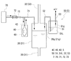
実施形態3として、図3に示すように、圧力調整バッグ40及びガス供給機構5を有する圧力調整機構4Cを備えることに加えて、ガス供給機構7を備えることができる。即ち、実施形態3に係るRF電池は、ガス供給機構7を備える点が実施形態2のRF電池と相違し、その他の構成は実施形態2と同様である。以下、実施形態2との相違点を中心に説明し、実施形態2と同様の構成については、図2と同一符号を付してその説明を省略する。図3の太実線矢印及び太破線矢印は、気体の流れを示す。
[Embodiment 3]
As a third embodiment, as shown in FIG. 3, in addition to the pressure adjustment mechanism 4 </ b> C having the
[ガス供給機構]
ガス供給機構7は、上述と同様の不活性ガスを含むフローガスを気相部20g、21gに供給する。そうして、気相部20g,21gに充満する発生ガスを希釈する。希釈した発生ガスは、ガス排出機構5により各タンク20、21の外へ排出できる。ここでは、ガス供給機構7は、ガス供給源70とガス供給導管71とを備える。
[Gas supply mechanism]
The
(ガス供給源)
ガス供給源70は、各タンク20,21に供給する不活性ガスを含むフローガスを貯留又は発生させる。ガス供給源70は、例えば、不活性ガスを貯留する貯留部材(ボンベ、タンクなど)を備える構成としても良いし、或いは不活性ガスを発生させるガス発生装置を備える構成としても良い。前者の構成は、簡単に構築することができ、好ましい。後者の構成は、不活性ガスの補充の手間を低減できる。特に、窒素を発生させるガス発生装置の場合、大気中から窒素を取り出すことができるので、半永久的にフローガスを供給することができる。
(Gas supply source)
The
フローガスにおける不活性ガスの割合は、99.9体積%以上であることが好ましい。この割合が高いほど、フローガスによる電解液の劣化を抑制することができる。この割合が99.9体積%以上であると、理論上、10年から20年に渡って運用上実害のない程度に電解液の劣化が抑制されると考えられる。 The ratio of the inert gas in the flow gas is preferably 99.9% by volume or more. The higher this ratio, the more the deterioration of the electrolyte solution caused by the flow gas can be suppressed. If this ratio is 99.9% by volume or more, it is theoretically considered that the deterioration of the electrolytic solution is suppressed to the extent that there is no practical damage from 10 to 20 years.
(ガス供給導管)
ガス供給導管71は、ガス供給源70から各タンク20,21の気相部20g,21gにフローガスを供給する(太実線矢印)。ガス供給導管71の一端は、ガス供給源70に接続され、ガス供給導管72の他端は、各タンク20、21の気相部20g,21gに開口している。このガス供給導管71には、気相部20g,21gへ常時フローガスを供給し続けるガス流量調整機構が設けられることが好ましい。
(Gas supply conduit)
The
〈ガス流量調整機構〉
ガス流量調整機構は、ガス供給源70から各タンク20,21に供給されるフローガスの供給量を所定値以上の一定量に調整する。ガス流量調整機構は、例えば、流量計72とバルブ73とを備える。流量計72は、ガス供給導管71に流通するフローガスの流量を計測する。バルブ73は、流量計72で計測した流量に基づいて流量が所定値以上で一定となるように弁の開度を調整してガス供給導管71に流通するフローガスの流量を調整する。流量に基づく開度の決定やバルブ73の動作は、図示しない制御部(例えば、コンピュータなど)によって行える。フローガスの各タンク20、21への供給量は、例えば、0.1リットル/分以上で一定とすることが好ましい。そうすれば、気相部20g、21gの発生ガスを十分に希釈でき、ガス排出機構5により希釈された発生ガスを排出すれば気相部20g,21gの換気を十分に行える。
<Gas flow adjustment mechanism>
The gas flow rate adjusting mechanism adjusts the supply amount of the flow gas supplied from the
[圧力調整機構]
圧力調整機構4Cは、実施形態2と同様、圧力調整バッグ40とガス排出機構5(水封弁50)とを備える。ここでは、圧力調整バッグ40は、ガス供給導管71を介して気相部20g,21gに連通している。具体的には、一端が圧力調整バッグ40に接続されて、他端がガス供給導管71の途中に連通される連通導管42が設けられている。
[Pressure adjustment mechanism]
Similar to the second embodiment, the pressure adjustment mechanism 4C includes a
圧力調整バッグ40は、各タンク20、21の気相部20g、21gが負圧になると、収縮して圧力調整バッグ40内の不活性ガスを図3の太実線矢印に示すように連通導管42を流通させてガス供給導管71に排出する。この不活性ガスは、ガス供給源70から送られる不活性ガスと合流して気相部20g,21gに供給される。そうして、気相部20g,21gの圧力を大気圧付近に上昇させる。気相部20g,21gの負圧が抑制されたら、ガス供給源70から送られる不活性ガスの一部が図3の太破線矢印に示すように連結導管42を介して圧力調整バッグ40内へ導入されて貯留される。
When the
ガス排出機構5は、ガス供給機構7により希釈された発生ガスを排出する。フローガスの供給により気相部20g、21gが正圧になれば、発生ガスは、上述したように、連結管52、調圧液51L、容器51の気相部51g、排出管53の順に通って、大気に排出される。ガス供給機構7により発生ガスを希釈できるため、発生ガスを低濃度の状態で大気中に排出できる。
The
〔作用効果〕
実施形態3のRF電池によれば、圧力調整バッグ40による負圧抑制に加えて、ガス供給機構7を備えることで、発生ガスを希釈でき、ガス排出機構5を備えることで、発生ガスを低濃度の状態で大気中に排出できる。そのため、各タンク20、21内を換気でき、タンク内に有害な発生ガスが滞留することを抑制できる。特に、常時、フローガスを供給し続ければ、気相部20g,21gの発生ガスを常に低濃度の状態に保っていられる。
[Function and effect]
According to the RF battery of the third embodiment, in addition to the negative pressure suppression by the
〔変形例1〕
変形例1として、各タンクの気相部同士を連通する気相連通管を備えることができる。上記気相連通管を備えることで、両タンクで一つの気相部と見做せる。そのため、圧力調整バッグは一方のタンクの気相部にのみ設けてもよい。また、ガス排出機構やガス供給機構を設ける場合、いずれも圧力調整バッグと同様、一方のタンクの気相部にのみ設けてもよい。例えば、圧力調整バッグ及びガス排出機構は負極電解液タンクに設け、ガス供給機構は正極電解液タンクに設けることが挙げられる。このとき、ガス供給導管から正極電解液タンクにフローガスを流すと、その一部は気相連通管を介して負極電解液タンクに導入される。RF電池では、負極電解液タンクで有害な発生ガスが発生し易い傾向にある。そのため、このように正極電解液タンクから負極電解液タンクにフローガスが流れるようにすれば、有害な発生ガスが正極電解液タンクに導入されることを回避できる。フローガスの供給量の調整は、例えば、負極電解液タンクの気相部へのフローガスの供給量が0.1リットル/分以上となるように行うとよい。そうすれば、各タンクの気相部の換気を十分に行える。
[Modification 1]
As a first modification, a gas phase communication pipe that communicates the gas phase portions of each tank can be provided. By providing the gas phase communication pipe, both tanks can be regarded as one gas phase portion. Therefore, you may provide a pressure regulation bag only in the gaseous-phase part of one tank. Moreover, when providing a gas discharge mechanism and a gas supply mechanism, all may be provided only in the gas phase part of one tank like a pressure regulation bag. For example, the pressure adjustment bag and the gas discharge mechanism are provided in the negative electrode electrolyte tank, and the gas supply mechanism is provided in the positive electrode electrolyte tank. At this time, when a flow gas is caused to flow from the gas supply conduit to the positive electrode electrolyte tank, a part of the flow gas is introduced into the negative electrode electrolyte tank via the gas phase communication pipe. In the RF battery, harmful generated gas tends to be easily generated in the negative electrode electrolyte tank. Therefore, if the flow gas flows from the positive electrode electrolyte tank to the negative electrode electrolyte tank in this way, it is possible to avoid introduction of harmful generated gas into the positive electrode electrolyte tank. The flow gas supply amount may be adjusted, for example, so that the flow gas supply amount to the gas phase portion of the negative electrode electrolyte tank is 0.1 liter / min or more. If it does so, the vapor phase part of each tank can fully be ventilated.
〔変形例2〕
変形例2として、ガス供給機構を備える場合、圧力調整バッグはガス供給導管を介して気相部に連通されず、気相部への直通導管により直接連通されていてもよい。
[Modification 2]
As a second modification, when the gas supply mechanism is provided, the pressure adjusting bag may not be communicated with the gas phase part via the gas supply conduit but may be directly communicated with the direct conduit to the gas phase part.
本発明の一態様に係る電解液循環型電池は、太陽光発電、風力発電などの新エネルギーの発電に対して、発電出力の変動の安定化、発電電力の余剰時の蓄電、負荷平準化などを目的とした用途に好適に利用することができる。また、本発明の一態様に係る電解液循環型電池は、一般的な発電所に併設されて、瞬低・停電対策や負荷平準化を目的とした大容量の蓄電池としても好適に利用することができる。 The electrolyte circulation type battery according to one embodiment of the present invention is a new energy generation such as solar power generation, wind power generation, stabilization of fluctuations in power generation output, power storage when surplus generated power, load leveling, etc. It can utilize suitably for the use which aimed at. In addition, the electrolyte circulation type battery according to one aspect of the present invention can be suitably used as a large-capacity storage battery that is installed in a general power plant for the purpose of instantaneous voltage drop, power failure countermeasures, and load leveling. Can do.
100 RF電池
10 電池セル
11 隔膜 12 正極セル 13 負極セル
14 正極電極 15 負極電極
20 正極電解液タンク 20g 気相部
21 負極電解液タンク 21g 気相部
30、31 供給流路 32、33 排出流路 34、35 ポンプ
4A、4B、4C 圧力調整機構
40 圧力調整バッグ
40a 防食層 40b 酸素遮断層
41 直通導管 42 連通導管
5 ガス排出機構
50 水封弁
51 容器 51g 気相部 51L 調圧液
52 連結管 53 排出管
60 収納箱
7 ガス供給機構
70 ガス供給源 71 ガス供給導管 72 流量計 73バルブ
110 呼吸袋(圧力調整バッグ)
DESCRIPTION OF
Claims (7)
前記タンクの気相部の圧力を調整する圧力調整機構を備え、
前記圧力調整機構は、前記タンクの外に設けられて、前記タンクの気相部の圧力変化に追従して膨張及び収縮する圧力調整バッグを備える電解液循環型電池。 An electrolyte circulation type battery including a tank for storing an electrolyte solution circulated in a battery cell,
A pressure adjusting mechanism for adjusting the pressure in the gas phase of the tank;
The pressure adjusting mechanism is an electrolyte circulation type battery including a pressure adjusting bag that is provided outside the tank and expands and contracts following a pressure change in a gas phase portion of the tank.
Priority Applications (7)
| Application Number | Priority Date | Filing Date | Title |
|---|---|---|---|
| JP2014152431A JP6308366B2 (en) | 2014-07-25 | 2014-07-25 | Electrolyte circulating battery |
| CN202110677992.1A CN113571741A (en) | 2014-07-25 | 2015-07-03 | Electrolyte circulation type battery |
| PCT/JP2015/069225 WO2016013377A1 (en) | 2014-07-25 | 2015-07-03 | Electrolytic solution circulation type battery |
| EP15824820.3A EP3174149B1 (en) | 2014-07-25 | 2015-07-03 | Electrolytic solution circulation type battery |
| US15/327,329 US10396372B2 (en) | 2014-07-25 | 2015-07-03 | Electrolytic solution circulation type battery |
| CN201580040252.XA CN106537675A (en) | 2014-07-25 | 2015-07-03 | Electrolytic solution circulation type battery |
| TW104122324A TWI631759B (en) | 2014-07-25 | 2015-07-09 | Electrolyte circulation type battery |
Applications Claiming Priority (1)
| Application Number | Priority Date | Filing Date | Title |
|---|---|---|---|
| JP2014152431A JP6308366B2 (en) | 2014-07-25 | 2014-07-25 | Electrolyte circulating battery |
Publications (2)
| Publication Number | Publication Date |
|---|---|
| JP2016031790A JP2016031790A (en) | 2016-03-07 |
| JP6308366B2 true JP6308366B2 (en) | 2018-04-11 |
Family
ID=55162909
Family Applications (1)
| Application Number | Title | Priority Date | Filing Date |
|---|---|---|---|
| JP2014152431A Active JP6308366B2 (en) | 2014-07-25 | 2014-07-25 | Electrolyte circulating battery |
Country Status (6)
| Country | Link |
|---|---|
| US (1) | US10396372B2 (en) |
| EP (1) | EP3174149B1 (en) |
| JP (1) | JP6308366B2 (en) |
| CN (2) | CN106537675A (en) |
| TW (1) | TWI631759B (en) |
| WO (1) | WO2016013377A1 (en) |
Families Citing this family (8)
| Publication number | Priority date | Publication date | Assignee | Title |
|---|---|---|---|---|
| KR101655292B1 (en) * | 2016-04-15 | 2016-09-07 | 스탠다드에너지(주) | Redox flow battery |
| WO2017183158A1 (en) * | 2016-04-21 | 2017-10-26 | 住友電気工業株式会社 | Container-type battery |
| US11791488B2 (en) | 2016-07-26 | 2023-10-17 | Sumitomo Electric Industries, Ltd. | Flow battery system |
| JP6153100B1 (en) * | 2016-07-26 | 2017-06-28 | 住友電気工業株式会社 | ELECTROLYTE SOLUTION FOR ELECTROLYTIC SOLUTION BATTERY AND ELECTROLYTE SOLUTION DISPERSION BATTERY SYSTEM |
| TWI626062B (en) * | 2017-03-10 | 2018-06-11 | 新利虹科技股份有限公司 | Operation method of breathing apparatus |
| CN111448699A (en) * | 2017-12-27 | 2020-07-24 | 昭和电工株式会社 | Redox flow battery |
| CN113036196A (en) * | 2019-12-09 | 2021-06-25 | 中国科学院大连化学物理研究所 | General device for reducing electrolyte migration of flow battery |
| US20240055642A1 (en) * | 2022-08-09 | 2024-02-15 | Ess Tech, Inc. | Negative electrolyte management system |
Family Cites Families (15)
| Publication number | Priority date | Publication date | Assignee | Title |
|---|---|---|---|---|
| US3751225A (en) * | 1970-03-02 | 1973-08-07 | Pollution Control Ind Inc | Sterilizing with liquid spray containing ozone |
| JPH01265825A (en) * | 1988-04-15 | 1989-10-23 | Matsushita Refrig Co Ltd | Fresh food-storage unit |
| US6244441B1 (en) * | 1999-11-10 | 2001-06-12 | Cryovac, Inc. | Heat sealable barrier film for fluid fillable packaging cushions and cushions made therefrom |
| JP3642732B2 (en) * | 2000-12-06 | 2005-04-27 | 住友電気工業株式会社 | Pressure fluctuation prevention tank structure, electrolyte circulation type secondary battery and redox flow type secondary battery |
| US7364815B2 (en) * | 2004-03-09 | 2008-04-29 | Matsushita Electric Industrial Co., Ltd. | Method of preserving fuel cell membrane electrode assembly |
| JP5148842B2 (en) * | 2006-05-18 | 2013-02-20 | 住友電気工業株式会社 | Redox flow battery |
| JP5217147B2 (en) * | 2006-10-18 | 2013-06-19 | トヨタ自動車株式会社 | Fuel cell system and method for adjusting water content of membrane |
| JP2009289535A (en) * | 2008-05-28 | 2009-12-10 | Toshiba Corp | Fuel cell |
| JP2010170782A (en) * | 2009-01-21 | 2010-08-05 | Sharp Corp | Redox flow battery, and method of charging and discharging the same |
| EP2290729B1 (en) * | 2009-08-24 | 2012-10-10 | Carl Freudenberg KG | Electric storage device with a volume compensation unit |
| CN102148388B (en) * | 2010-02-10 | 2013-08-28 | 大连融科储能技术发展有限公司 | Redox flow battery system |
| EP2631977A4 (en) * | 2010-10-21 | 2014-10-08 | Nissan Motor | Method for operating fuel cell system |
| WO2012117543A1 (en) * | 2011-03-02 | 2012-09-07 | 日新電機株式会社 | Power storage battery |
| JP2014127263A (en) * | 2012-12-25 | 2014-07-07 | Mitsubishi Motors Corp | Redox flow battery |
| CN103730677A (en) * | 2014-01-26 | 2014-04-16 | 湖南省银峰新能源有限公司 | Intelligent control system of vanadium redox battery |
-
2014
- 2014-07-25 JP JP2014152431A patent/JP6308366B2/en active Active
-
2015
- 2015-07-03 CN CN201580040252.XA patent/CN106537675A/en active Pending
- 2015-07-03 WO PCT/JP2015/069225 patent/WO2016013377A1/en active Application Filing
- 2015-07-03 CN CN202110677992.1A patent/CN113571741A/en active Pending
- 2015-07-03 US US15/327,329 patent/US10396372B2/en active Active
- 2015-07-03 EP EP15824820.3A patent/EP3174149B1/en active Active
- 2015-07-09 TW TW104122324A patent/TWI631759B/en active
Also Published As
| Publication number | Publication date |
|---|---|
| TW201611401A (en) | 2016-03-16 |
| JP2016031790A (en) | 2016-03-07 |
| CN113571741A (en) | 2021-10-29 |
| US20170194660A1 (en) | 2017-07-06 |
| EP3174149A1 (en) | 2017-05-31 |
| EP3174149A4 (en) | 2017-07-12 |
| WO2016013377A1 (en) | 2016-01-28 |
| EP3174149B1 (en) | 2018-08-29 |
| US10396372B2 (en) | 2019-08-27 |
| TWI631759B (en) | 2018-08-01 |
| CN106537675A (en) | 2017-03-22 |
Similar Documents
| Publication | Publication Date | Title |
|---|---|---|
| JP6308366B2 (en) | Electrolyte circulating battery | |
| JP3642732B2 (en) | Pressure fluctuation prevention tank structure, electrolyte circulation type secondary battery and redox flow type secondary battery | |
| JP6633571B2 (en) | Hydrogen production equipment and hydrogen production system | |
| JP5148842B2 (en) | Redox flow battery | |
| WO2015174283A1 (en) | Redox flow battery | |
| WO2015174282A1 (en) | Redox flow battery | |
| WO2019111886A1 (en) | Fuel cell system and control method for fuel cell system | |
| TWI753206B (en) | Redox flow battery | |
| JP2012160344A (en) | Tank of electrolyte circulation battery, and electrolyte circulation battery | |
| JP2015232960A (en) | Battery system | |
| JPWO2019106722A1 (en) | Redox flow battery | |
| WO2017022313A1 (en) | Tank-type power generation device capable of producing high-pressure hydrogen and fuel-cell vehicle | |
| JP6030239B2 (en) | Industrial battery adapter plug | |
| JP6268531B2 (en) | Redox flow battery | |
| JP5685748B1 (en) | High-pressure hydrogen tank and fuel cell vehicle capable of producing hydrogen | |
| JP2014092185A (en) | Fluid supply system | |
| GB2578611A (en) | Pressure regulator | |
| JP2006339095A (en) | Gas pipe for fuel cell and fuel cell system | |
| JP2011192538A (en) | Fuel cell system |
Legal Events
| Date | Code | Title | Description |
|---|---|---|---|
| A621 | Written request for application examination |
Free format text: JAPANESE INTERMEDIATE CODE: A621 Effective date: 20170220 |
|
| TRDD | Decision of grant or rejection written | ||
| A01 | Written decision to grant a patent or to grant a registration (utility model) |
Free format text: JAPANESE INTERMEDIATE CODE: A01 Effective date: 20180214 |
|
| A61 | First payment of annual fees (during grant procedure) |
Free format text: JAPANESE INTERMEDIATE CODE: A61 Effective date: 20180227 |
|
| R150 | Certificate of patent or registration of utility model |
Ref document number: 6308366 Country of ref document: JP Free format text: JAPANESE INTERMEDIATE CODE: R150 |
|
| R250 | Receipt of annual fees |
Free format text: JAPANESE INTERMEDIATE CODE: R250 |
|
| R250 | Receipt of annual fees |
Free format text: JAPANESE INTERMEDIATE CODE: R250 |
|
| R250 | Receipt of annual fees |
Free format text: JAPANESE INTERMEDIATE CODE: R250 |
|
| R250 | Receipt of annual fees |
Free format text: JAPANESE INTERMEDIATE CODE: R250 |