EP2290621A2 - Magnetische Wasserzeichenmarkierung eines gedruckten Substrats mittels metamerer Darstellung - Google Patents
Magnetische Wasserzeichenmarkierung eines gedruckten Substrats mittels metamerer Darstellung Download PDFInfo
- Publication number
- EP2290621A2 EP2290621A2 EP10173641A EP10173641A EP2290621A2 EP 2290621 A2 EP2290621 A2 EP 2290621A2 EP 10173641 A EP10173641 A EP 10173641A EP 10173641 A EP10173641 A EP 10173641A EP 2290621 A2 EP2290621 A2 EP 2290621A2
- Authority
- EP
- European Patent Office
- Prior art keywords
- colorant mixture
- magnetic
- substrate
- colorant
- image
- Prior art date
- Legal status (The legal status is an assumption and is not a legal conclusion. Google has not performed a legal analysis and makes no representation as to the accuracy of the status listed.)
- Ceased
Links
Images


Classifications
-
- G—PHYSICS
- G07—CHECKING-DEVICES
- G07D—HANDLING OF COINS OR VALUABLE PAPERS, e.g. TESTING, SORTING BY DENOMINATIONS, COUNTING, DISPENSING, CHANGING OR DEPOSITING
- G07D7/00—Testing specially adapted to determine the identity or genuineness of valuable papers or for segregating those which are unacceptable, e.g. banknotes that are alien to a currency
- G07D7/005—Testing security markings invisible to the naked eye, e.g. verifying thickened lines or unobtrusive markings or alterations
-
- G—PHYSICS
- G07—CHECKING-DEVICES
- G07D—HANDLING OF COINS OR VALUABLE PAPERS, e.g. TESTING, SORTING BY DENOMINATIONS, COUNTING, DISPENSING, CHANGING OR DEPOSITING
- G07D7/00—Testing specially adapted to determine the identity or genuineness of valuable papers or for segregating those which are unacceptable, e.g. banknotes that are alien to a currency
- G07D7/003—Testing specially adapted to determine the identity or genuineness of valuable papers or for segregating those which are unacceptable, e.g. banknotes that are alien to a currency using security elements
- G07D7/0034—Testing specially adapted to determine the identity or genuineness of valuable papers or for segregating those which are unacceptable, e.g. banknotes that are alien to a currency using security elements using watermarks
-
- Y—GENERAL TAGGING OF NEW TECHNOLOGICAL DEVELOPMENTS; GENERAL TAGGING OF CROSS-SECTIONAL TECHNOLOGIES SPANNING OVER SEVERAL SECTIONS OF THE IPC; TECHNICAL SUBJECTS COVERED BY FORMER USPC CROSS-REFERENCE ART COLLECTIONS [XRACs] AND DIGESTS
- Y10—TECHNICAL SUBJECTS COVERED BY FORMER USPC
- Y10T—TECHNICAL SUBJECTS COVERED BY FORMER US CLASSIFICATION
- Y10T428/00—Stock material or miscellaneous articles
- Y10T428/24—Structurally defined web or sheet [e.g., overall dimension, etc.]
- Y10T428/24802—Discontinuous or differential coating, impregnation or bond [e.g., artwork, printing, retouched photograph, etc.]
- Y10T428/24835—Discontinuous or differential coating, impregnation or bond [e.g., artwork, printing, retouched photograph, etc.] including developable image or soluble portion in coating or impregnation [e.g., safety paper, etc.]
Definitions
- This application relates to the useful manipulation of magnetic components found in toners as commonly utilized in various printer and electrostatographic print environments. More specifically, the present disclosure relates to at least one realization of magnetic encoding of data elements or magnetic marks in combination with distraction patterns.
- watermarking is a common way to ensure security in digital documents.
- One prior art approach is to use special ink rendering where the inks are invisible under standard illumination. These inks normally respond to light outside the visible range and thereby may be made visible. Examples of such extra-spectral techniques are UV (ultra-violet) and IR (infrared).
- UV ultraviolet
- IR infrared
- a document may include a non-magnetic substrate, a first colorant mixture printed as a first image upon the substrate, the first colorant mixture including a magnetic ink, and a second colorant mixture printed as a second image upon the substrate in substantially close spatial proximity to the printed first colorant mixture.
- the second colorant mixture may consist essentially of one or more non-magnetic inks and exhibit properties of both low visual contrast and high magnetic contrast against the first colorant mixture, such that the resultant printed substrate does not reveal the first image to the human eye, but will reveal the first image to a magnetic image reader.
- a method for creating a mark on a document may include printing at least one first colorant mixture as a first image upon a non-magnetic substrate, the first colorant mixture having a property of high magnetic contrast in relation to the substrate, and printing at least one second colorant mixture as a second image upon the substrate in substantially close spatial proximity to the printed first colorant mixture, the second colorant mixture having a property of low magnetic contrast in relation to the substrate and a property of low visual contrast in comparison to the first colorant mixture.
- a document may include a non-magnetic substrate, a first colorant mixture printed as a first image upon the substrate, the first colorant mixture having a property of high magnetic contrast in conjunction with the substrate, and a second colorant mixture printed as a second image upon the substrate in substantially close spatial proximity to the printed first colorant mixture, the second colorant mixture having a property of low magnetic contrast in conjunction with the substrate, and a property of low visual contrast against the first colorant mixture, such that the resultant printed substrate image will yield a discernable pattern evident as a magnetic mark when viewed with a magnetic image reader.
- the first colorant mixture is comprised of predominately black colorant
- the second colorant mixture is comprised of yellow, cyan and magenta
- the first and second colorant mixtures exhibit substantially similar grayscale values.
- the first colorant mixture and the second colorant mixture are a close metameric color match under normal illumination but differ in their response under magnetic sensing.
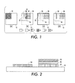
- FIG. 1 schematically depicts metameric situations where different colorant combinations and distributions lead to identical visual impressions under normal illumination according to an embodiment.
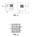
- FIG. 2 schematically depicts in cross-sectional profile two instances where a single visual color black is achieved with different colorant combinations according to an embodiment.
- FIG. 3 depicts a method of using colorant or colorant mixtures to render an example alphanumeric character according to an embodiment.
- FIG. 4 depicts a method of creating an example alphanumeric character utilizing colorant mixture patterns including a colorant mixture distraction pattern.
- FIG. 5 depicts two colorant mixtures that yield identical Lab values, but which have different magnetic response properties according to an embodiment.
- FIG. 6 depicts a magnetic coding of a magnetic mark in the form of an "X", where the magnetic mark is formed through the use of MICR black toner according to an embodiment.
- data refers to information in numeric form that can be digitally transmitted or processed.
- An “image”, as a pattern of physical light or a collection of data representing said physical light, may include characters, words, and text as well as other features such as graphics.
- a “digital image”, by extension, is an image represented by a collection of digital data.
- An image may be divided into “segments,” each of which is itself an image.
- a segment of an image may be of any size up to and including the whole image.
- image object or “object” as used herein is generally equivalent to the term “segment” and will be employed herein interchangeably. In the event that one term or the other is deemed to be narrower or broader than the other, the teaching as provided herein and claimed below is directed to the more broadly determined definitional term, unless that term is otherwise specifically limited within the claim itself.
- each element of data may be called a "pixel,” which is common usage in the art and refers to a picture element.
- Each pixel has a location and value.
- Each pixel value may be one or more bits in a binary form, a gray scale value in a gray scale form, or a set of color space coordinates in a color coordinate form.
- the binary form, gray scale form, and color coordinate form may each form a two-dimensional array defining an image.
- An operation performs "image processing" when it operates on an item of data that relates to part of an image.
- Contrast is used to denote the visual difference between items, data points, and the like. It can be measured as a color difference or as a luminance difference or both.
- a "digital color printing system” is an apparatus arrangement suited to accepting image data and rendering that image data upon a substrate.
- a "colorant” is one of the fundamental subtractive C, M, Y, K primaries (cyan, magenta, yellow, and black) which may be realized in formulation as liquid ink, solid ink, dye, electrostatographic toner, or other printable material.
- a "colorant mixture” is a particular combination of C, M, Y, K colorants.
- Toner refers to the wet or dry material that forms an image or text on a substrate.
- ink and toner are used interchangeably to refer to this material.
- Magnetic ink may refer to ink that is used in magnetic ink character recognition (“MICR"), a character recognition technology where MICR characters are printed with magnetic ink or toner.
- MICR magnetic ink character recognition
- Positive additives to the magnetic ink or toner may include iron oxide.
- Non-magnetic ink may refer to an ink that does not exhibit a magnetic field or only exhibits a nominal magnetic field that is substantially and measurably different from that of magnetic ink.
- Metal rendering or “metameric printing” is the ability to use multiple colorant combinations to render a single visual color, as can be achieved when printing with more than three colorants. It is understood, in this context, that an ideal metameric match may only be achieved in non-realistic laboratory viewing conditions and that here, and in the subsequent paragraphs, the term is used to indicate a practical visual match given the viewing environment of the user.
- FIG. 1 depicts a conceptualization of metameric printing for a human observer.
- the visual response for a human observer is in most practical applications described sufficiently with a three component system, such as that defined by the International Commission on Illumination ("CIE").
- CIE International Commission on Illumination
- all four areas 10 in FIGs. 1(a), (b), (c), and (d) will result in the same visual response under normal illumination, which also may be referred to by those skilled in the art as having the same Lab values.
- different amounts of yellow 20, magenta 30, cyan 40 and black 50 colorant are deposited, as in a standard four color printing process. Also, dependent on the overlap provided with the different colorants, the mixtures blue 35 and red 45 are created from cyan 40 and magenta 30, or yellow 20 and magenta 30 respectively.
- FIG. 2 in cross-section conceptually shows different ways in which the visual color black can be achieved either by using a black colorant 50, or in the alternative by the superposition of yellow 20, magenta 30, and cyan 40, colorants as printed onto the substrate print surface 60.
- An important aspect depicted by FIG. 2 is that a single color, in this case black, can be achieved by a multitude of metameric colorant combinations, of which but two are shown in this example.
- every system that maps N components to n components with N>n will have a multitude of ways to accomplish this mapping. It is understood by those skilled in the art that singularities might exist in the mapping so that certain visual triplets can only be achieved with a single or a small number of colorant quadruplets.
- utilization of more than the standard four colorants is comprehended and contemplated in the claims below, and only omitted for clarity of explanation as being redundant and unnecessary for those skilled in the art.
- the same visual color can be achieved with different amounts and combinations of the respective available colorants. From FIGs. 1(c) and (d) it should be clear from noting the overlap of magenta 30 and cyan 40 in (c), that the same amount of colorants have been used and all that has been changed is the spatial distribution only. In examples provided in FIGs. 1 (a) and (b) however, the black colorant 50 provided there could conceptually be replaced by a super imposition of the three colorants yellow 20, magenta 30 and cyan 40 as is indicated in FIG. 2 without changing the visual perception of the color.
- the techniques taught herein work by finding colorant mask patterns that have identical CIE Lab values and so are hard to distinguish from each other under normal light.
- the colorant mask patterns may exhibit very dissimilar magnetic responses, and thus display a high magnetic contrast with respect to one another when read by a magnetic reading device. This dissimilarity in magnetic responses under magnetic sensing can be easily detected with an image-based magnetic sensor, which may in essence be a magnetic camera.
- One example embodiment employs this difference by toggling between the black visual color caused by using a black colorant that exhibits a first magnetic property, and the black visual color caused by a combination of the cyan, magenta and yellow colorants that exhibits a different magnetic property, alternating the placement of each between either the background or foreground areas in close spatial proximity and complementary counter-opposition.
- FIG. 3 shows an exemplary application of the teachings enumerated above.
- a document may include a non-magnetic substrate, a first colorant mixture 300, and a second colorant mixture 301.
- the first colorant mixture 300 may be printed as a first image upon the substrate.
- the first colorant mixture 300 may include magnetic ink.
- the first colorant mixture 300 may have a property of high magnetic contrast in conjunction with the substrate.
- the second colorant mixture 301 may be printed as a second image upon the substrate in substantially close spatial proximity to the printed first colorant mixture 300.
- substantially close spatial proximity means that the two images have boundaries that abut each other, overlap, or are so close to each other that the boundary is not visually perceptible to a human under ordinary ambient viewing conditions.
- the second colorant mixture 301 may consist essentially of one or more non-magnetic inks and exhibit properties of both low visual contrast and high magnetic contrast against the first colorant mixture 300 such that the resultant printed substrate does not reveal the first image to the human eye but may reveal the first image to a magnetic image reader.
- the second colorant mixture 301 may have a property of low magnetic contrast in conjunction with the substrate, and a property of low visual contrast against the first colorant mixture 300, such that the resultant printed substrate image will yield a discernable pattern evident as a magnetic mark when viewed with a magnetic image reader.
- low visual contrast means that a visual comparison of two printed items exhibits no perceptible color change.
- High magnetic contrast means that, when two materials printed on a substrate are compared, one exhibits a significantly greater magnetic response than the other.
- the first colorant mixture 300 may exhibit a visual color and the second colorant mixture 301 may exhibit the same visual color.
- the first colorant mixture 300 may include predominately black colorant.
- the first colorant mixture may be a carbon black toner or ink.
- the second colorant mixture 301 may include yellow, cyan, and magenta.
- the first and second colorant mixtures 300 and 301 may exhibit substantially similar grayscale values.
- the first colorant mixture 300 and the second colorant mixture 301 may further be a close metameric color match under normal illumination but different in their response under magnetic sensing.
- the substrate may be paper.
- the substrate may be a transparency, packaging material, plastic, or other medium on which toner may be printed.
- Each colorant mixture 300 or 301 may be either a single CMYK colorant or any mixture of CMYK colorants. They will, however, differ in that colorant mixture 301 will be selected so as to provide higher magnetic response than that selected for colorant mixture 300, or vice versa. However, in some embodiments, the colorant mixtures 300 and 301 will be selected most optimally to match each other closely in their average color under normal light, while at the same time differing in their average magnetic response.
- area 302 under normal illumination, area 302 would look to a human observer as a constant or quasi constant color or pattern, while under magnetic sensing tool area 302 would separate into two distinct areas represented by colorant mixtures 300 and 301 exhibiting a clear contrast to a magnetic sensitive device such as a magnetic camera or MICR reader device.
- a magnetic sensitive device such as a magnetic camera or MICR reader device.
- the magnetic sensitive device would show an image 303 in which the magnetic ink is highlighted, and the image 303 formed by the magnetic ink is revealed.
- the document may further include a third colorant mixture 304 printed as a third image 305 upon the substrate.
- the third colorant mixture 304 may exhibit a visual color and/or magnetic field strength that differs from that of the first colorant mixture 300 and/or the second colorant mixture 301.
- an approximately 50% grayscale gray colorant mixture may be realized with a halftone of black colorant only. This may then be matched against a colorant mixture comprising a high amount of yellow mixed with enough cyan and magenta to yield a similar approximate 50% grayscale gray colorant mixture.
- the single colorant halftone case will provide much higher absorption of magnetic ink as compared to the colorant mixture.
- two colorant mixtures may be realized which while appearing quite nearly identical under normal viewing illumination, will never-the-less appear quite different to the appropriate device under magnetic sensing conditions.
- a method for creating a mark on a document may include printing at least one first colorant mixture 300 as a first image 303 upon a non-magnetic substrate, and printing at least one second colorant mixture 301 as a second image upon the substrate in substantially close spatial proximity to the printed first colorant mixture 300.
- the first colorant mixture 300 may have a property of high magnetic contrast in relation to the substrate
- the second colorant mixture 301 may have a property of low magnetic contrast in relation to the substrate and a property of low visual contrast in comparison to the first colorant mixture 300.
- the method may further include printing a third image on the substrate.
- the third image may include at least the first colorant mixture and the second colorant mixture arranged in close spatial proximity to each other.
- the spatial image arrangement of the at least two colorant mixtures may reveal a magnetic mark to a suitable magnetic image reader.
- the method may further include printing a third colorant mixture 304 as a third image 305 upon the substrate.
- the third colorant mixture 304 may exhibit a magnetic field strength that differs from than of the first colorant mixture 300. It is understood that printing of this third colorant mixture is preferably done as an overprint (addition) to the previously deposited colorant mixtures rather than as a replacement of the previously deposited colorant mixtures. For FIG. 3 , this means that the colorant mixture 304 will result in two colorant mixtures 304/300 and 304/301 dependent on the previously deposited colorant mixture 300 or 301 at the location.
- the two colorant mixtures may be printed onto the substrate in the form of a distraction pattern.
- FIG. 4 illustrates an example of such an embodiment.
- a spatial distraction pattern may be introduced with the differing colorant mixture selections described above. Each resultant color spatial pattern will on average have some given color appearance when viewed under normal light, and will exhibit, on average, some given level of magnetic response when viewed under magnetic sensing.
- FIG. 4 depicts where one simple type of magnetic mark is simply a text string comprised of alphanumeric characters.
- the alphanumeric letter 403 selected in this FIG. 4 is an "O", and it can be represented as a two-state image--one state for the text image shape and the other state for the background.
- two spatial color patterns 401 and 402 are provided, each corresponding to one of the two states.
- the two spatial colorant patterns are designed to have substantially similar average colors under normal light and yet substantially different magnetic responses.
- the two spatial colorant patterns 401 and 402 are each provided as a repeating spatial pattern mosaic combination of one or more colors, each color in turn being itself either a single colorant or a CMYK colorant mixture.
- CMYK1, CMYK2, CMYK3, and CMYK4 there are contemplated four colorant mixtures, indicated as: CMYK1, CMYK2, CMYK3, and CMYK4. Fewer colorant mixtures may be used as will be discussed below, and as will be obvious to one skilled in the art more colorant mixtures may be employed as well.
- CMYK2 and CMYK2 are used to make up the first spatial colorant pattern 401.
- CMYK3 and CMYK4 are used to make up the second spatial colorant pattern 402.
- the distraction pattern actually employed in this embodiment is a diamond checkerboard, but those skilled in the art will recognize the possibility of being able to select any number of other patterns, as for example a simple orthogonal checkerboard, or polka-dots.
- This pattern will act as a distraction to the eye and make it more difficult to discern the swapping between text/image and background.
- the actual distraction pattern granularity size is somewhat variable, flexible and empirical. The most optimum results are dependent upon the desired font or image size; the target print system to be employed for rendering; as well as the visual acuity of the target observer. Exemplary results will be realized when the spatial pattern used is the same or quite similar for both spatial colorant patterns 401 and 402.
- the second spatial colorant pattern 402 is selected and applied to fill patch area 403, which is arranged in this example as an image depicting the alphanumeric symbol "O".
- the first spatial colorant pattern 401 is selected and applied to patch area 402 arranged here in substantially close spatial proximity to patch area 403, and thereby effecting a background pattern around patch area 403.
- Both the spatial colorant patterns 401 and 402 are exemplarily arranged so that the pattern appears to be nearly continuous across patch 402 and patch 403.
- the two spatial colorant patterns are designed to have substantially similar average colors under normal light and substantially different average magnetic response, they may have at least one CMYK colorant mixture in common.
- CMYK2 may be identical with CMYK4. This would mean that CMYK2 and CMYK3 would to have substantially similar average color levels under normal light and substantially different magnetic responses.
- This magnetic mark comprises a magnetic readable substrate, and a first spatial colorant mixture pattern printed as an image upon the substrate.
- the first spatial colorant mixture pattern has the characteristic of low magnetic readability, as well as a property of low color contrast under normal illumination against a second spatial colorant mixture pattern.
- the second spatial colorant mixture pattern has a high magnetic readability, and printed in close spatial proximity to the first colorant mixture pattern, such that the resulting printed image suitably exposed to a magnetic read device, will yield a discernable pattern evident as a magnetic mark to the appropriate magnetic sensing device.
- FIG. 5 depicts two colorant mixtures 501 and 502 yielding identical visual response, or identical Lab values, but maximally different magnetic response through utilizing non-magnetic ink in one mixture and MICR black toner in the other according to an embodiment.
- the two colorant mixtures 501 and 502 may be two CMYK quadruplets yielding the identical visual response, or Lab values. However, these two CMYK quadruplets yield maximally different magnetic response, assuming non-magnetic CMY toners 503 and MICR black toner 504 are utilized.
- the two colorant mixtures 501 and 502 of FIG. 5 may follow the general design specifications of U.S. Application Publication No. 2008/0299333 entitled "Substrate Fluorescent Non-Overlapping Dot Patterns for Embedding Information in Printed Documents.” Additional and/or alternate designs of color patches may also be used within the scope of this disclosure.
- FIG. 6 depicts a magnetic coding of a magnetic mark 601 in the form of an "X", where the magnetic mark 601 is formed through the use of MICR black toner 504 according to an embodiment.
- the mark 601 in the form of an "X" may be encoded to be detectable by its magnetic response while not being visible in normal viewing conditions.
- arbitrary magnetic coding that can be read by a magnetic detector may be performed. Additional and/or alternate magnetic coding may also be used within the scope of this disclosure.
Landscapes
- Physics & Mathematics (AREA)
- General Physics & Mathematics (AREA)
- Engineering & Computer Science (AREA)
- Computer Security & Cryptography (AREA)
- Printing Methods (AREA)
- Credit Cards Or The Like (AREA)
- Accessory Devices And Overall Control Thereof (AREA)
- Image Processing (AREA)
- Editing Of Facsimile Originals (AREA)
- Inks, Pencil-Leads, Or Crayons (AREA)
- Magnetic Record Carriers (AREA)
Applications Claiming Priority (1)
| Application Number | Priority Date | Filing Date | Title |
|---|---|---|---|
| US12/546,848 US9892585B2 (en) | 2009-08-25 | 2009-08-25 | Magnetic watermarking of a printed substrate by metameric rendering |
Publications (2)
| Publication Number | Publication Date |
|---|---|
| EP2290621A2 true EP2290621A2 (de) | 2011-03-02 |
| EP2290621A3 EP2290621A3 (de) | 2011-11-02 |
Family
ID=43086117
Family Applications (1)
| Application Number | Title | Priority Date | Filing Date |
|---|---|---|---|
| EP10173641A Ceased EP2290621A3 (de) | 2009-08-25 | 2010-08-23 | Magnetische Wasserzeichenmarkierung eines gedruckten Substrats mittels metamerer Darstellung |
Country Status (3)
| Country | Link |
|---|---|
| US (2) | US9892585B2 (de) |
| EP (1) | EP2290621A3 (de) |
| JP (1) | JP5869756B2 (de) |
Families Citing this family (15)
| Publication number | Priority date | Publication date | Assignee | Title |
|---|---|---|---|---|
| JP5131144B2 (ja) * | 2008-10-20 | 2013-01-30 | 富士ゼロックス株式会社 | 画像処理装置、画像処理プログラム、画像形成装置 |
| US8064100B2 (en) * | 2008-12-05 | 2011-11-22 | Xerox Corporation | Watermark encoding and detection using narrow band illumination |
| US9892585B2 (en) | 2009-08-25 | 2018-02-13 | Xerox Corporation | Magnetic watermarking of a printed substrate by metameric rendering |
| US9593982B2 (en) | 2012-05-21 | 2017-03-14 | Digimarc Corporation | Sensor-synchronized spectrally-structured-light imaging |
| US8994734B2 (en) | 2012-07-31 | 2015-03-31 | Xerox Corporation | Package definition system |
| US9314986B2 (en) | 2012-10-31 | 2016-04-19 | Xerox Corporation | Method and system for applying an adaptive perforation cut to a substrate |
| US8869083B1 (en) | 2013-05-29 | 2014-10-21 | Xerox Corporation | Dynamic bridge generation in package definition systems |
| US9621760B2 (en) * | 2013-06-07 | 2017-04-11 | Digimarc Corporation | Information coding and decoding in spectral differences |
| US9916399B2 (en) | 2014-05-05 | 2018-03-13 | Xerox Corporation | Dynamic optimization of detailed flat design based on desired final structural attributes |
| JP2016057125A (ja) * | 2014-09-08 | 2016-04-21 | セイコーNpc株式会社 | 磁気ラインセンサ及びこの磁気ラインセンサを用いた画像化装置 |
| US9736330B2 (en) | 2015-05-19 | 2017-08-15 | Xerox Corporation | Method and system for applying a content-variable watermark to a document |
| US9961230B2 (en) | 2015-05-26 | 2018-05-01 | Xerox Corporation | Method and system for applying a watermark to a document |
| WO2019170927A1 (es) * | 2018-03-07 | 2019-09-12 | Sotec Consulting Sl | Método y sistema de verificacion automática de la autenticidad de documentos |
| CN109726788B (zh) * | 2018-12-21 | 2022-03-04 | 北京印刷学院 | 同色异谱隐藏的明暗双码二维码 |
| US11912055B2 (en) | 2022-04-05 | 2024-02-27 | Xerox Corporation | Method and system for printing variable images |
Citations (4)
| Publication number | Priority date | Publication date | Assignee | Title |
|---|---|---|---|---|
| US3000000A (en) | 1955-05-06 | 1961-09-12 | Gen Electric | Automatic reading system |
| US5734752A (en) | 1996-09-24 | 1998-03-31 | Xerox Corporation | Digital watermarking using stochastic screen patterns |
| US20070017990A1 (en) | 2005-07-19 | 2007-01-25 | Fuji Xerox Co., Ltd. | Document correction detection system and document tampering prevention system |
| US20080299333A1 (en) | 2007-05-29 | 2008-12-04 | Xerox Corporation | Substrate fluorescent non-overlapping dot patterns for embedding information in printed documents |
Family Cites Families (23)
| Publication number | Priority date | Publication date | Assignee | Title |
|---|---|---|---|---|
| GB8514391D0 (en) * | 1985-06-07 | 1985-07-10 | De La Rue Thomas & Co Ltd | Authenticity sensing |
| IT1263970B (it) * | 1993-02-11 | 1996-09-05 | Mantegazza A Arti Grafici | Dispositivo di sicurezza antifalsificazione per documenti in genere |
| US7941534B2 (en) | 1997-04-14 | 2011-05-10 | Carlos De La Huerga | System and method to authenticate users to computer systems |
| US6243504B1 (en) * | 1998-08-19 | 2001-06-05 | International Business Machines Corporation | Integrated magnetic ink character recognition system and method therefor |
| JP4524371B2 (ja) * | 2000-10-23 | 2010-08-18 | 独立行政法人 国立印刷局 | 磁気情報記録印刷物及びその真偽判別方法 |
| DE10131153A1 (de) * | 2001-06-28 | 2003-01-16 | Giesecke & Devrient Gmbh | Sicherheitselement |
| US20030211299A1 (en) * | 2001-09-27 | 2003-11-13 | 3M Innovative Properties Company | Adhesion-enhancing surfaces for marking materials |
| US20040170912A1 (en) * | 2002-12-06 | 2004-09-02 | Brennan Michael W. | Color and process color dry toners and compatible toning systems for use in high-speed electrographic digital printing |
| JP2006039478A (ja) | 2004-07-30 | 2006-02-09 | Canon Inc | 画像処理装置 |
| EP1646056A1 (de) * | 2004-10-09 | 2006-04-12 | European Central Bank | Sicherheitsdokument auf dem Daten gespeichert werden können und Verfahren und Vorrichtung zum Lesen und Schreiben von Daten vom bzw. auf das Sicherheitsdokument |
| US20060230273A1 (en) * | 2005-04-08 | 2006-10-12 | Eastman Kodak Company | Hidden MIRC printing for security |
| US7628555B2 (en) | 2006-03-15 | 2009-12-08 | Kyocera Mita Corporation | Method of image forming and image forming apparatus |
| US8332949B2 (en) * | 2006-04-28 | 2012-12-11 | Hewlett-Packard Development Company, L.P. | Methods for making an authenticating system for an object |
| US8101326B2 (en) * | 2006-05-19 | 2012-01-24 | Eastman Kodak Company | Secure document printing method and system |
| JP2008085695A (ja) | 2006-09-28 | 2008-04-10 | Fujitsu Ltd | 電子透かし埋め込み装置および検出装置 |
| US8068684B2 (en) | 2007-05-04 | 2011-11-29 | I.R.I.S. | Compression of digital images of scanned documents |
| US8455087B2 (en) | 2007-06-05 | 2013-06-04 | Xerox Corporation | Infrared encoding of security elements using standard xerographic materials with distraction patterns |
| US8460781B2 (en) | 2007-06-05 | 2013-06-11 | Xerox Corporation | Infrared encoding of security elements using standard xerographic materials |
| US7852515B2 (en) | 2007-06-05 | 2010-12-14 | Xerox Corporation | Infrared encoding for embedding multiple variable data information collocated in printed documents |
| JP5044841B2 (ja) | 2007-06-19 | 2012-10-10 | 独立行政法人 国立印刷局 | 偽造防止印刷物 |
| JP4527752B2 (ja) * | 2007-06-22 | 2010-08-18 | 日立オムロンターミナルソリューションズ株式会社 | 紙葉類識別装置及びそのセンサ部 |
| US9892585B2 (en) | 2009-08-25 | 2018-02-13 | Xerox Corporation | Magnetic watermarking of a printed substrate by metameric rendering |
| JP5636885B2 (ja) | 2010-11-08 | 2014-12-10 | 株式会社リコー | 画像処理装置、画像形成装置、及び画像処理システム |
-
2009
- 2009-08-25 US US12/546,848 patent/US9892585B2/en active Active
-
2010
- 2010-08-18 JP JP2010182871A patent/JP5869756B2/ja not_active Expired - Fee Related
- 2010-08-23 EP EP10173641A patent/EP2290621A3/de not_active Ceased
-
2018
- 2018-01-17 US US15/873,213 patent/US10176658B2/en active Active
Patent Citations (4)
| Publication number | Priority date | Publication date | Assignee | Title |
|---|---|---|---|---|
| US3000000A (en) | 1955-05-06 | 1961-09-12 | Gen Electric | Automatic reading system |
| US5734752A (en) | 1996-09-24 | 1998-03-31 | Xerox Corporation | Digital watermarking using stochastic screen patterns |
| US20070017990A1 (en) | 2005-07-19 | 2007-01-25 | Fuji Xerox Co., Ltd. | Document correction detection system and document tampering prevention system |
| US20080299333A1 (en) | 2007-05-29 | 2008-12-04 | Xerox Corporation | Substrate fluorescent non-overlapping dot patterns for embedding information in printed documents |
Also Published As
| Publication number | Publication date |
|---|---|
| JP2011050055A (ja) | 2011-03-10 |
| EP2290621A3 (de) | 2011-11-02 |
| US9892585B2 (en) | 2018-02-13 |
| US10176658B2 (en) | 2019-01-08 |
| JP5869756B2 (ja) | 2016-02-24 |
| US20110052888A1 (en) | 2011-03-03 |
| US20180144572A1 (en) | 2018-05-24 |
Similar Documents
| Publication | Publication Date | Title |
|---|---|---|
| US10176658B2 (en) | Magnetic watermarking of a printed substrate by metameric rendering | |
| US8455087B2 (en) | Infrared encoding of security elements using standard xerographic materials with distraction patterns | |
| US8460781B2 (en) | Infrared encoding of security elements using standard xerographic materials | |
| US7852515B2 (en) | Infrared encoding for embedding multiple variable data information collocated in printed documents | |
| US8283004B2 (en) | Substrate fluorescence pattern mask for embedding information in printed documents | |
| US8111432B2 (en) | Infrared watermarking of photographic images by matched differential black strategies | |
| US8730527B2 (en) | Embedding infrared marks in gloss security printing | |
| EP1997642B1 (de) | Verfahren für fluoreszente nicht überlappende Punktdesignmuster für Substrate zur Einbettung von Informationen in Druckdokumente | |
| US8335342B2 (en) | Protecting printed items intended for public exchange with information embedded in blank document borders | |
| US8224019B2 (en) | Embedding information in document blank space | |
| EP2724331B1 (de) | Kodierung verborgener information in räumlichen netzfrequenzen | |
| US8980504B2 (en) | Substrate fluorescence mask utilizing a multiple color overlay for embedding information in printed documents | |
| JP7416671B2 (ja) | 赤外線ボイドパンタグラフマークを使用した文書セキュリティの検証 | |
| US11102372B2 (en) | Information recording body, medium and printed product | |
| US8373895B2 (en) | Prevention of unauthorized copying or scanning | |
| MXPA06002451A (es) | Sistema y metodo para autenticar un articulo. | |
| US11006021B1 (en) | Non-copy correlation mark | |
| US9538041B1 (en) | System and method for producing seesaw gloss effect and recording medium with seesaw gloss effect | |
| US11872833B2 (en) | Infrared effect preserved on copy | |
| EP2946341B1 (de) | Verfahren zum drucken eines druckmaterials mit einem optisch lesbaren code | |
| US9516190B1 (en) | System and method for producing seesaw gloss effect and recording medium with seesaw gloss effect | |
| KR20080083993A (ko) | 보안 인쇄 시스템 및 그 보안 인쇄 방법 | |
| Eschbach et al. | Creating variable data infrared signals for security applications |
Legal Events
| Date | Code | Title | Description |
|---|---|---|---|
| PUAI | Public reference made under article 153(3) epc to a published international application that has entered the european phase |
Free format text: ORIGINAL CODE: 0009012 |
|
| AK | Designated contracting states |
Kind code of ref document: A2 Designated state(s): AL AT BE BG CH CY CZ DE DK EE ES FI FR GB GR HR HU IE IS IT LI LT LU LV MC MK MT NL NO PL PT RO SE SI SK SM TR |
|
| AX | Request for extension of the european patent |
Extension state: BA ME RS |
|
| PUAL | Search report despatched |
Free format text: ORIGINAL CODE: 0009013 |
|
| AK | Designated contracting states |
Kind code of ref document: A3 Designated state(s): AL AT BE BG CH CY CZ DE DK EE ES FI FR GB GR HR HU IE IS IT LI LT LU LV MC MK MT NL NO PL PT RO SE SI SK SM TR |
|
| AX | Request for extension of the european patent |
Extension state: BA ME RS |
|
| RIC1 | Information provided on ipc code assigned before grant |
Ipc: G07D 7/00 20060101ALI20110929BHEP Ipc: G07D 7/04 20060101AFI20110929BHEP |
|
| 17P | Request for examination filed |
Effective date: 20120502 |
|
| 17Q | First examination report despatched |
Effective date: 20161109 |
|
| 18R | Application refused |
Effective date: 20171204 |