EP2290420B1 - Procédé d'assemblage d'une pile à plaque-miroir - Google Patents
Procédé d'assemblage d'une pile à plaque-miroir Download PDFInfo
- Publication number
- EP2290420B1 EP2290420B1 EP09168979.4A EP09168979A EP2290420B1 EP 2290420 B1 EP2290420 B1 EP 2290420B1 EP 09168979 A EP09168979 A EP 09168979A EP 2290420 B1 EP2290420 B1 EP 2290420B1
- Authority
- EP
- European Patent Office
- Prior art keywords
- mirror
- mirror plate
- plate
- plates
- handling tool
- Prior art date
- Legal status (The legal status is an assumption and is not a legal conclusion. Google has not performed a legal analysis and makes no representation as to the accuracy of the status listed.)
- Not-in-force
Links
- 238000000034 method Methods 0.000 title claims description 87
- 230000003287 optical effect Effects 0.000 claims description 99
- 125000006850 spacer group Chemical group 0.000 claims description 40
- 239000011521 glass Substances 0.000 claims description 37
- 239000000463 material Substances 0.000 claims description 11
- 238000000926 separation method Methods 0.000 claims description 9
- 238000001093 holography Methods 0.000 claims description 3
- 238000005305 interferometry Methods 0.000 claims description 3
- 230000010354 integration Effects 0.000 description 15
- 238000005259 measurement Methods 0.000 description 12
- 238000013459 approach Methods 0.000 description 10
- 238000004519 manufacturing process Methods 0.000 description 7
- 238000003384 imaging method Methods 0.000 description 6
- XUIMIQQOPSSXEZ-UHFFFAOYSA-N Silicon Chemical compound [Si] XUIMIQQOPSSXEZ-UHFFFAOYSA-N 0.000 description 4
- 238000010586 diagram Methods 0.000 description 4
- 229910052710 silicon Inorganic materials 0.000 description 4
- 239000010703 silicon Substances 0.000 description 4
- 238000009825 accumulation Methods 0.000 description 2
- 238000012512 characterization method Methods 0.000 description 2
- 239000003795 chemical substances by application Substances 0.000 description 2
- 238000013329 compounding Methods 0.000 description 2
- 238000011161 development Methods 0.000 description 2
- 230000018109 developmental process Effects 0.000 description 2
- 238000005323 electroforming Methods 0.000 description 2
- 239000005357 flat glass Substances 0.000 description 2
- 230000005484 gravity Effects 0.000 description 2
- 239000002245 particle Substances 0.000 description 2
- 238000009304 pastoral farming Methods 0.000 description 2
- 230000000717 retained effect Effects 0.000 description 2
- 239000000758 substrate Substances 0.000 description 2
- 238000004154 testing of material Methods 0.000 description 2
- 238000012876 topography Methods 0.000 description 2
- 238000004876 x-ray fluorescence Methods 0.000 description 2
- 238000000560 X-ray reflectometry Methods 0.000 description 1
- 238000004026 adhesive bonding Methods 0.000 description 1
- 238000010420 art technique Methods 0.000 description 1
- 230000004323 axial length Effects 0.000 description 1
- 239000004568 cement Substances 0.000 description 1
- 239000000919 ceramic Substances 0.000 description 1
- 238000000576 coating method Methods 0.000 description 1
- 238000007796 conventional method Methods 0.000 description 1
- 230000001419 dependent effect Effects 0.000 description 1
- 238000013461 design Methods 0.000 description 1
- 238000005516 engineering process Methods 0.000 description 1
- 238000002474 experimental method Methods 0.000 description 1
- 230000004907 flux Effects 0.000 description 1
- 239000002241 glass-ceramic Substances 0.000 description 1
- 239000003292 glue Substances 0.000 description 1
- 229910052737 gold Inorganic materials 0.000 description 1
- 229910052741 iridium Inorganic materials 0.000 description 1
- 238000005304 joining Methods 0.000 description 1
- 238000001459 lithography Methods 0.000 description 1
- 239000002184 metal Substances 0.000 description 1
- 229910052751 metal Inorganic materials 0.000 description 1
- 229910001092 metal group alloy Inorganic materials 0.000 description 1
- 239000000203 mixture Substances 0.000 description 1
- 238000012634 optical imaging Methods 0.000 description 1
- 229910052697 platinum Inorganic materials 0.000 description 1
- 239000011148 porous material Substances 0.000 description 1
- 230000008092 positive effect Effects 0.000 description 1
- 238000002360 preparation method Methods 0.000 description 1
- 230000035945 sensitivity Effects 0.000 description 1
- 238000010998 test method Methods 0.000 description 1
- 235000012431 wafers Nutrition 0.000 description 1
Images


Classifications
-
- G—PHYSICS
- G21—NUCLEAR PHYSICS; NUCLEAR ENGINEERING
- G21K—TECHNIQUES FOR HANDLING PARTICLES OR IONISING RADIATION NOT OTHERWISE PROVIDED FOR; IRRADIATION DEVICES; GAMMA RAY OR X-RAY MICROSCOPES
- G21K1/00—Arrangements for handling particles or ionising radiation, e.g. focusing or moderating
- G21K1/06—Arrangements for handling particles or ionising radiation, e.g. focusing or moderating using diffraction, refraction or reflection, e.g. monochromators
-
- G—PHYSICS
- G02—OPTICS
- G02B—OPTICAL ELEMENTS, SYSTEMS OR APPARATUS
- G02B7/00—Mountings, adjusting means, or light-tight connections, for optical elements
- G02B7/18—Mountings, adjusting means, or light-tight connections, for optical elements for prisms; for mirrors
- G02B7/182—Mountings, adjusting means, or light-tight connections, for optical elements for prisms; for mirrors for mirrors
- G02B7/183—Mountings, adjusting means, or light-tight connections, for optical elements for prisms; for mirrors for mirrors specially adapted for very large mirrors, e.g. for astronomy, or solar concentrators
-
- G—PHYSICS
- G21—NUCLEAR PHYSICS; NUCLEAR ENGINEERING
- G21K—TECHNIQUES FOR HANDLING PARTICLES OR IONISING RADIATION NOT OTHERWISE PROVIDED FOR; IRRADIATION DEVICES; GAMMA RAY OR X-RAY MICROSCOPES
- G21K2201/00—Arrangements for handling radiation or particles
- G21K2201/06—Arrangements for handling radiation or particles using diffractive, refractive or reflecting elements
- G21K2201/064—Arrangements for handling radiation or particles using diffractive, refractive or reflecting elements having a curved surface
-
- G—PHYSICS
- G21—NUCLEAR PHYSICS; NUCLEAR ENGINEERING
- G21K—TECHNIQUES FOR HANDLING PARTICLES OR IONISING RADIATION NOT OTHERWISE PROVIDED FOR; IRRADIATION DEVICES; GAMMA RAY OR X-RAY MICROSCOPES
- G21K2201/00—Arrangements for handling radiation or particles
- G21K2201/06—Arrangements for handling radiation or particles using diffractive, refractive or reflecting elements
- G21K2201/067—Construction details
-
- Y—GENERAL TAGGING OF NEW TECHNOLOGICAL DEVELOPMENTS; GENERAL TAGGING OF CROSS-SECTIONAL TECHNOLOGIES SPANNING OVER SEVERAL SECTIONS OF THE IPC; TECHNICAL SUBJECTS COVERED BY FORMER USPC CROSS-REFERENCE ART COLLECTIONS [XRACs] AND DIGESTS
- Y10—TECHNICAL SUBJECTS COVERED BY FORMER USPC
- Y10T—TECHNICAL SUBJECTS COVERED BY FORMER US CLASSIFICATION
- Y10T156/00—Adhesive bonding and miscellaneous chemical manufacture
- Y10T156/10—Methods of surface bonding and/or assembly therefor
- Y10T156/1002—Methods of surface bonding and/or assembly therefor with permanent bending or reshaping or surface deformation of self sustaining lamina
Definitions
- the invention relates to a method for assembling a mirror plate stack comprising a plurality of mirror plates and a base plate onto which the plurality of mirror plates are stacked.
- a particular, but non-exhaustive, application of the invention lies in space missions involving the observation of particular regions of space in the X-ray ranges or for high-energy particles using space telescopes that comprise optical modules based on stacked mirror plates. Nevertheless, the invention can be applied in numerous other fields: UV optics for lithographic equipment, medical diagnostic equipment, material testing and characterization equipment, imaging X-ray fluorescence analyzers, etc.
- the thickness of these mirrors plates is typically very small compared to the surface diameter; by way of example thin plates or coaxial shells with a surface area of a DIN A4 sheet and a thickness ⁇ 0.5 mm are used.
- This thickness (or thinness) requirement of the mirrors presents an opto-mechanical challenge in mounting them without compromising their figure for focusing since such a mirror plate deforms easily under its own weight and by any inadvertent handling or frictional forces.
- High-precision measurements with an angular resolution of a few arc seconds require that the thin mirrors are to be aligned and mounted with precision at a level of about a micrometer or a fraction thereof.
- Marco Beijersbergen ET AL (Development of X-ray pore optics: novel high-resolution silicon millipore optics for XEUS and ultralow mass glass micropore optics for imaging and timing), 2004, Proceedings of SPIE, Vol. 5539, pages 104-115 , discloses a method of producing X-ray optics, wherein the optics are made by stacking plates which are made from rectangular cuts of silicon wafers. This document discloses automated assembly facilities for the production of these stacks.
- Initially flat sheets e.g. made of glass, must be formed into the required shape.
- the flat glass sheets are placed onto a properly shaped mandrel, and then heated in an oven to the temperature, at which the glass sheet softens and bends under its own weight.
- the temperature is low enough for the glass sheets to keep their surface finish, but high enough for the sheets to conform to the shape of the supporting mandrel.
- An alternative approach utilizes gas pressure for forming the glass plate.
- the glass plate is sandwiched between a set of two mandrels and air cushions are between the upper mandrel and the upper side of the glass plate and the lower side of the glass plate and the lower mandrel, respectively.
- the mirror plates are removed from the slumping mandrel by means of a separate handling tool in order to be inspected and measured, then aligned and mounted into the optical module or unit structure.
- a separate handling tool in order to be inspected and measured, then aligned and mounted into the optical module or unit structure.
- Prior art methods employ a temporary mounting of the slumped mirror plates to perform the metrology.
- the temporary mounting of the mirror plates is followed by a final permanent mounting of the mirror plates.
- the temporary mounting equipment may cause additional distortions to the mirror plates. This temporary mounting equipment is also required for the handling of the mirror plate during the integration of the plate into the X-ray optical module.
- a typical optical module might contain about 100 mirror pairs in e.g. a Wolter-1 configuration.
- a total of e.g. 60 of such modules form the complete telescope aperture.
- Such mirror pairs e.g. two mirror plate stacks arranged in a tandem configuration for a Wolter-1 configuration, are usually assembled by pairwise mounting and aligning two corresponding mirrors, one of each mirror plate stacks, e.g. two mirror plate stacks are assembled in parallel.
- determining the plate position before the final alignment and bonding is completed does not allow for determining the final position of the mirror plates to a high degree of accuracy.
- the need for a box-like structure to fix the mirror plates during the stacking procedure does not allow for an accurate measurement of the entire figure and position of the aligned mirror plate since part of the mirror plate figure or surface are covered by the box-like mounting structure.
- two corresponding mirror plate stacks i.e. two mirror plate stacks later to be combined into an optical unit such as a Wolter-1 configuration, are assembled in parallel by pairwise mounting and aligning two corresponding mirrors of each mirror plate stacks.
- the critical alignment between the two mirror plate stacks can therefore only be conducted at the time of stacking, using only visible optical metrology which makes it difficult to accurately align the two mirror plate stack relative to each other.
- It is a further disadvantage in some prior art methods that only a small fraction of the mirror is sampled and accessible to metrology during the alignment since the mirror area that is exposed via the slots of the conventional handling tools are limited.
- a method for assembling a mirror plate stack comprising a plurality of mirror plates and a rigid base plate onto which the plurality of mirror plates are stacked.
- the plates including the base plate, i.e. the plate at what is called the "bottom” or the "top” of the stack, can be shaped in such a manner that the front reflecting faces thereof have a well-determined shape.
- the mirror plates may have a light curvature and/or the shape of coaxial shells.
- the method comprises the steps of providing a base plate to which mirror plates are mounted.
- the base plate serves as a rigid carrier plate or structural substrate onto which the mirror plates are assembled.
- the mirror plates may be glass mirror plates but the present invention is not restricted thereto.
- the mirror plates could equally well be, for example, silicon, metal, metal alloys, ceramics, or glass-ceramics mirror plates.
- the method further comprises the step of providing a handling tool with a second mirror plate.
- the method further comprises the step of providing a spacer to a first surface of the second mirror plate.
- the spacer is formed as spacer ribs.
- the ribs may constitute integral portions of the plates or they may be made separately.
- the method further comprises the step of positioning the handling tool comprising the second mirror plate with the spacer to align the second mirror plate with the first mirror plate, wherein the second mirror plate is aligned relative to the first mirror plate based on a measured position and shape of the first mirror plate to compensate a deviation of the measured position and shape of the first mirror platefrom a pre-defined position and shape of the first mirror plate.
- the handling tool comprising the second mirror plate with the spacer to align the second mirror plate with the first mirror plate
- the second mirror plate is aligned relative to the first mirror plate based on a measured position and shape of the first mirror plate to compensate a deviation of the measured position and shape of the first mirror platefrom a pre-defined position and shape of the first mirror plate.
- the mirror plate shape may comprise the plate geometry and figure.
- the measured position and shape of the n mirror plate may then be used for the subsequent positioning and mounting of the following (n+1) th mirror plate to compensate the measured errors or deviation of the position and shape of the preceding n th plate.
- the metrology data acquired on the preceding plate when positioning and aligning the following plate, an accumulation of errors in the stacking process is avoided.
- the method further comprises the step of attaching the second mirror plate to the first mirror plate by bonding the spacer to the first mirror plate, wherein the spacer determines a pre-defined distance between the first and the second mirror plates.
- the method further comprises the step of exposing a second surface of the second mirror plate by removing the handling tool from the attached second mirror plate.
- the method further comprises the step of measuring the position and shape of the attached second mirror plate after the second surface of the second mirror plate has been exposed.
- the first surface of the second mirror plate comprises the spacer and is facing the preceding plate and mounted thereto, whereas the second surface of the second mirror is fully exposed and accessible for metrology after the handling tool has been removed.
- the actual plate position and shape is determined after the alignment and bonding is completed, thus preventing mirror plate measurements from being distorted by further mounting procedures in case a temporary mounting was used.
- the final position and shape of the mounted mirror plates can therefore be measured more accurately.
- the complete surface of the mirror plate that has been mounted to the preceding plate is exposed and accessible for measurement, preferably using optical metrology or profilometers to accurately measure the position and shape of the mirror plate.
- the measured position and shape of a mirror plate may be used for the subsequent positioning of the following plate to compensate any deviation from a pre-determined position and shape of the assembled second mirror plate.
- a mirror plate stack may comprise 20 to 30 mirror plates.
- the method may further include the following steps: providing the base plate; providing the handling tool with the first mirror plate; providing a spacer to a first surface of the first mirror plate; positioning the handling tool comprising the first mirror plate with the spacer for aligning the first mirror plate with the base plate; attaching the first mirror plate to the base plate by bonding the spacer to the base plate; exposing a second surface of the first mirror plate by removing the handling tool from the attached first mirror plate; and measuring the position and shape of the first mirror plate after the second surface has been exposed.
- the assembly of the first mirror plate onto the base plate differs from the assembly of a subsequent mirror plate mainly in that the first mirror plate is aligned relative to the base plate itself and mounted directly thereon.
- the thickness of the mirror plates is small compared to the mirror area and may be 1 mm or less at a given mirror surface area of, for example, 300 cm 2 .
- Rib spacing is to be chosen according to the required angle, resolution, material properties and dimensions.
- the mirror plates are aligned by means of mechanical and optical alignment methods that utilize reference items provided on the handling tool and the base plate.
- the mechanical and optical alignment methods do achieve the required accuracy.
- the size is in the order of 1 arc second and 1 micron.
- the reference items may be optical mirrors for a precise angular measurement or surface marks for mechanical/ tactile scanning. These reference items may also be used for the above-mentioned step of measuring the position and shape of the attached second mirror plate after the second surface of the second mirror plate has been exposed.
- the base plate onto which the mirror plates have been stacked may be used as a carrier plate for interfacing the mirror plate stack with an optical bench.
- the base plate or "backplane" is not only designed and used as a temporary tool during stacking only, but the optical module baseplate used during the stacking process itself can also be retained and used as a structural element to later interface the mirror plate assembly to an optical bench or to another mirror plate stack.
- the bonding of all mirror plates during the integration process, including the first one attached directly to the base plate is permanent. It is therefore an advantage of the present invention that only one precision base plate is required.
- the plates are automatically aligned to the optical module structural interfaces upon completion of the plate integration.
- the position and shape in the step of measuring the position and shape of the attached mirror plate after the second surface has been exposed, may be measured using metrology or profilometers.
- the optical methods to measure the position and shape include Computer generated holography and interferometry.
- the position and shape may be measured to the required accuracy, preferably as less than 1 arc second and less than 1 micron.
- the handling tool is a mandrel
- the method may further comprise the step of forming and/or fabricating the mirror plate to a pre-defined shape by means of the mandrel.
- various types of mandrels exist for slumping, electro-forming or fabricating the plate to a pre-defined shape.
- the mirror plates may also be obtained by electroforming.
- the mirror plates may be glass mirror plates and the mandrel may be a glass slumping mandrel.
- the initially flat mirror sheets, e.g. made of glass are formed into the required shape by placing them on a properly shaped mandrel.
- the mandrel and the mirror sheet are then heated in an oven to the temperature, at which the sheet softens and bends under its own weight.
- the temperature is low enough for the sheets to keep their surface finish, but high enough for the sheets to conform to the shape of the supporting mandrel.
- the same tool for forming the initially flat mirror sheets into the pre-determined form as well as for positioning and aligning the formed mirror plate with the base plate and/ or a preceding mirror plate already mounted into the plate stack allows to increase the stacking accuracy and to reduce costs.
- the formed mirror plate is already precisely aligned on the handling tool.
- the optical axis of the handling tool (being the mandrel for forming the mirror plate) is known to large accuracy, and therefore also for the mirror plate.
- an additional handling procedure such as suspending the plate on thin wires and bonding it to a temporary structure or gluing bonding clips to the mirror plate to position the mirror plate can be avoided which could distort the thin mirror plates by any inadvertent handling or simply by the mirror plate's own weight.
- glass plates formed by slumping in a gas flow between mandrels according to the above mentioned approach of the prior art, for example.
- the glass plate has to be positioned onto the handling tool.
- the method may further comprise the step of removably attaching the second surface of the mirror plate to the handling tool by means of a separation layer wherein a sticking coefficient of the separation layer is set to a value to hold the mirror plate in a fixed position during the step of positioning the handling tool comprising the mirror plate with the spacer means, and wherein after the step of attaching the mirror plate, the value of the sticking coefficient allows a removal of the handling tool from the attached mirror plate.
- the base plate and/or the spacer means are made of the same material as the mirror plate material. This ensures that all the components of the mirror plate stack have the same coefficient of thermal expansion (CTE) and the same optical properties.
- the base plate and the spacer may be made of a material with a coefficient of thermal expansion (CTE) that is within acceptable limits for the given thermal environment during production and operation.
- a method for assembling an optical unit comprising a first optical mirror plate stack and a second optical mirror plate stack, wherein said first mirror plate stack and said second optical mirror plate stack comprising a plurality of mirror plates stacked onto a base plate.
- the method comprises the steps of mounting the first optical mirror plate stack and the second optical mirror plate stack via their base plates onto micro-manipulator means wherein the first and the second optical mirror plate stacks are placed in tandem, i.e. are arranged into a tandem configuration and wherein the first and the second optical mirror plate stacks can be positioned relative to each other by the micro-manipulator means.
- the method comprises the steps of aligning the first optical mirror plate stack relative to the second optical mirror plate stack by means of X-ray metrology.
- the alignment between the first and the second mirror plate stack is conducted using X-ray metrology, wherein the actual optical performance and imaging properties of the complete system comprising the two mirror plate stacks is measured in X-rays which allows to accurately align the two stacks with respect to each other using micro-positioners holding the two plate stacks at their base plates.
- the alignment method intrinsically considers all the mirror plates simultaneously, and performs a direct measurement to high accuracy and fidelity. According to conventional methods, this critical alignment between the mirror plates of the first stack and the mirror plates of the second stack is conducted at the time of stacking, using visible optical metrology. This implies some potential error sources: Firstly, X-ray metrology is not possible and therefore the inferior (due to diffraction limitations) visible light metrology must be employed.
- the method may further comprise the steps of securing the aligned position of the first optical mirror plate stack relative to the second optical mirror plate stack by connecting the first mirror plate stack and the second mirror plate stack via their base plates.
- the joint base plates may contain also the interface for the attachment to an optical bench, for example, using isostatic mounting.
- the first mirror plate stack may be a mirror plate stack of parabolically shaped glass mirror plates and the second mirror plate stack may be a mirror plate stack of hyperbolically shaped glass mirror plates forming a Wolter-1 element.
- the two stacks placed in tandem are combining surfaces of revolution that are of parabolic and hyperbolic shape.
- the invention achieves the objects it set out to achieve.
- it makes it possible to reduce considerably the overall manufacturing costs for a mirror plate assembly while significantly improving the accuracy for assembling the mirror plate stack.
- mirror plate assembly method is in particular suitable for assembling mirror plate stacks for use in high-performance X-ray optics, e.g. to assemble a glass X-ray optical unit.
- the present invention is not restricted thereto. The invention finds applications in numerous other fields.
- Mirror plate stacks and optical units assembled according to this invention may also be used for high-precision UV optics for lithographic equipment, for medical diagnostic equipment, material testing and characterization equipment, or imaging X-ray fluorescence analyzers.
- the above-described method for assembling an optical unit having a first optical mirror plate stack and a second optical mirror plate stack is not restricted to the assembly of Wolter telescope of type 1, i.e. the first mirror plate stack having parabolically shaped glass mirror plates and the second mirror plate stack having hyperbolically shaped glass mirror plates but is also applicable for the assembly of Wolter-2, Kirkpatrick-Baez geometries or other configurations based on the alignment of at least two mirror plate stacks positioned relative to each other.
- a single stack of a multitude of plates can also be produced, as described. This could be used for point-to-point imaging and flux concentrations or collimators and utilized for lithography equipment, for example.
- Fig. 1 shows a flow diagram of steps involved in assembling a mirror plate stack according to an embodiment of the invention.
- a handling tool is provided with a mirror plate positioned thereon.
- the mirror plate is a glass mirror plate and the handling tool is a glass slumping mandrel.
- the glass mirror plate is formed to a pre-defined shape by the glass slumping mandrel.
- spacer ribs are attached to the mirror plate surface.
- the steps S4 -S7 describe the case where at least one mirror plate has already been assembled to a base plate.
- a base plate is provided with a mirror plate mounted thereto.
- the handling tool i.e.
- the slumping mandrel comprising the mirror plate with the spacer is positioned to align the mirror plate with the mirror plate that has been lastly mounted to the base plate.
- the mirror plate is aligned relative to the already mounted mirror plate based on a measured position and shape of the mounted mirror plate to compensate a deviation of the measured position and shape of the mounted mirror plate from a pre-defined position and shape of the mounted mirror plate.
- step S7 the mirror plate that is still positioned on the handling tool, is attached to the mounted mirror plate by bonding the spacer ribs to the mounted mirror plate, wherein the spacer ribs determine a pre-defined spacing between the two mirror plates.
- step S8 the handling tool is removed from the attached second mirror plate and thereby exposes the mirror plate surface that was in contact with the handling tool.
- step S9 the position and shape of the attached mirror plate is measured after its surface has been exposed.
- Fig. 1 The steps illustrated in Fig. 1 describe the assembly of two successive plates 10.
- This stack structure as described in Fig. 1 and in Fig. 8 constitutes an optical reflector element in accordance with the invention that can be referred to as being "minimal".
- the number of stacked plates is generally much greater, typically being of the order of a few tens.
- 20 to 30 plates are stacked one on another.
- the above-described steps S1-S9 are therefore repeated to stack a plurality of mirror plates onto the base plate.
- the first mirror plate is assembled according to the following steps: the base plate is provided; the handling tool comprising the first mirror plate with the spacer ribs is positioned for aligning the first mirror plate with the base plate. Then, the first mirror plate is attached to the base plate by bonding the spacer ribs to the base plate. The attached first mirror plate is then measured according to steps S8 and S9.
- the above-described sequence of steps S1 to S3 and S4 to S9 may be conducted independent from each other.
- step S1 to S3 using the slumping mandrel onto which the mirror plate was formed to a pre-determined shape as the handling tool for the subsequent positioning and alignment of the mirror plate (steps S1 to S3) may also be used with another method for mounting the mirror plate into a mirror plate assembly.
- aligning and mounting a mirror plate into a mirror plate assembly based on the measured position and shape of a previous mirror plate does not require the use of a mandrel as the handling tool.
- the combination of both approaches results in an assembly method of higher accuracy since a mandrel is particularly suitable for accurately positioning a mirror plate relative to a preceding mirror plate already mounted into the mirror plate assembly.
- Fig. 2 shows a flow diagram of steps involved in assembling an optical unit based on two mirror plate stacks arranged in a tandem configuration according to an example being useful for the understanding of the invention.
- step S10 two mirror plate stacks assembled according to the method of this invention are provided.
- the first mirror plate stack comprises parabolically shaped glass mirror plates and the second mirror plate stack comprises hyperbolically shaped glass mirror plates.
- step S11 the first optical mirror plate stack and the second optical mirror plate stack are mounted via their base plates onto micro-manipulator means wherein the first and the second optical mirror plate stacks are arranged into a tandem configuration and wherein the first and the second optical mirror plate stacks are positioned relative to each other by the micro-manipulator means.
- step S13 the first optical mirror plate stack is aligned relative to the second optical mirror plate stack by means of X-ray metrology.
- step S14 the aligned position of the first optical mirror plate stack relative to the second optical mirror plate stack is secured by connecting the first mirror plate stack and the second mirror plate stack via their base plates.
- step S15 interface means are attached to the connected base plates of the first and second optical mirror plate stack.
- step S16 the interface means are connected by means of isostatic mounting interfaces to an optical bench.
- the interface means may also be part of the base plates themselves avoiding distortions and errors during a later integration.
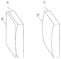
- FIG. 3A shows schematically a slumping mandrel 11 and a mirror plate 10 before a slumping process.
- the technique of glass slumping is based on the fact that the viscosity of glass changes with temperature. By increasing the temperature above the strain point it becomes soft enough to deform under its own gravity and slumps into a given mould.
- the starting mirror plates 10 are display glass sheets, e.g. of type D 263 T produced by Schott.
- the selected glass sheets are typically the size of an A4 sheet, and between 0.3 and 0.5 mm thick. These sheets are flat, and must be formed into the required shape.
- the flat glass sheet 10 is placed onto a properly shaped slumping mandrel 11 and then heated in an oven to the temperature at which the glass sheet softens and bends under its own weight.
- the temperature is low enough for the glass sheets to keep their surface finish, but high enough for the sheets to conform to the shape of the supporting mandrel 11.
- a separation agent is required between the glass sheet 10 and the mandrel 11 to avoid sticking.
- grazing incidence angles and high-Z material coatings e.g. Pt, Ir or Au
- Fig 3b shows the mirror plate 10 after the slumping process where the glass mirror plates 10 has been shaped into a pre-defined form as defined by the slumping mandrel 11.
- the plates 10 can be curved so that the reflecting front faces occupy a surface of predetermined shape, for example, a surface of revolution that may be parabolic, elliptical, or hyperbolic.
- the shape can be convex or concave.
- the mirror plates 10 can be made to lightly stick to the mandrel 11, by fine-tuning the separation layer composition and preparation process used to form it.
- the sticking coefficient of the separation agent between the glass sheet 10 and the mandrel 11 is set to a value that is strong enough to hold the mirror plate in a fixed position on the mandrel during a subsequent positioning process of the mandrel, but also light enough so that the mirror plate can be removed from the mandrel after the mirror plate has been mounted into the mirror plate stack.
- spacer ribs 12 are attached to the slumped mirror plate 10 on a slumping mandrel 11.
- the ribs 12 are attached to the back of the plate when it is still on the slumping mandrel.
- the spacer ribs 12 are glued to the mirror plate surface so that the spacer ribs are regularly spaced apart.
- the ribs 12 are of the same material as the mirror plates.
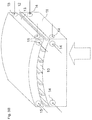
- Fig. 5a illustrates the step of positioning of the slumping mandrel 11 comprising a mirror plate 10 with attached spacer ribs 12 for aligning the mirror plate 10 with a base plate 13.
- the slumping mandrel 11 serves as the handling tool for stacking the slumped mirror plate 10 into a mirror plate stack.
- the mandrel 11 with the lightly attached mirror plate 10 is positioned with respect to a base plate 13.
- the mirror plate 10 Due to the slumping process, the mirror plate 10 is already aligned on the handling tool 11, since this is the actual mandrel used to slump the plate 10 in the previous production step.
- the optical axis of the handling tool being the slumping mandrel 11 is known to large accuracy, and therefore also the optical axis for the mirror plate 10.
- the tuning of the sticking coefficient of the separation layer ensures that the mirror plate adheres sufficiently to the mandrel after the slumping process, allowing the required later handling. At the same time the adhesion is light enough to permit separation from the mandrel at the required stage. Consequently, no further separate precision tool is necessary for positioning and aligning the slumped mirror plate 10, other than the slumping mandrel 11.
- Fig. 5b the use of mechanical and optical alignment methods is illustrated indicated by the arrows in Fig. 5b .
- reference items (14, 15) on the handling tool i.e. the slumping mandrel
- Optical references such as optical mirrors are used as the reference items. Since the geometry of the mandrel 11 and the base plate 13 is known to a large degree of accuracy, the optical mirrors can be fixed on an exact position with respect to the mandrel and the base plate.
- Optical references 14 are fixed on two adjacent sides of the handling tool below the surface area on which the mirror plate is positioned. Additional optical references 15 are fixed on the corresponding positions of the handling tool.
- 5b indicate, for example, laser beams which are reflected by the optical mirrors during the alignment process of the handling tool.
- the position of the mandrel relative to the base plate or the already assembled reference plates can be determined with the required accuracy, which may be 1 micrometer example given.
- the metrology is not limited by the diffraction of limited small beam reflections though narrow channels (as it is the case in conventional stacking methods).
- the spacer ribs 12 are bonded to the base plate 13, or the preceding mirror plate 10 that was stacked in the previous step. A spacing between two successive plates is determined by the spacer ribs 12.
- the handling tool 11 is separated from the mirror plate 10.
- the bonding material e.g. glue or cement
- the figure of the mirror plate 10 is largely defined by the figure of the mandrel 11.
- the mirror plate figure is maintained by the handling tool 11, from the time the plate is thermally slumped to conform to the mandrel 11, and up to the time when the plate 10 is firmly and permanently bonded to the structural support or the previous plate.
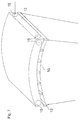
- Fig. 6 illustrates a based plate comprising a mounted mirror plate and a slumping mandrel that has been removed from the mounted mirror plate 10, i.e., after the mirror plate 10 has been mounted.
- the mirror surface previously facing the handling tool is fully exposed and available for metrology based on optical imaging or scanning methods, e.g. using computer generated holography (CGH) and interferometry. It is advantageous that the mirror surface is fully exposed and is not partly covered by an optical module box or a temporary mounting structure which would prevent an exact measurement of an entire mirror surface or figure.
- CGH computer generated holography
- the position, topography and figure of an exposed surface of a mounted mirror plate is measured.
- the topography can also be measured by another test method.
- the actual mounting position of the mirror plate and any figure errors are accurately determined and recorded.
- the optical references 15 that have been used as reference items to position and align a mirror plate with the base plate and/or a mirror plate already mounted on the mirror plate stack are also used for measuring the position and shape of the attached mirror plate after the surface of the mirror plate that was facing the mandrel has been exposed by removing the mandrel. The difference between the desired position and figure and the actual position and figure of the mounted mirror plate determines the position and figure errors.
- the mounting and alignment process is repeated with the next plate to be mounted onto the mirror plate stack which shows the mounting of a mirror plate 10 to another mirror plate 10 already mounted to a base plate 13.
- the next mirror plate 10 is slumped on a mandrel 11, spacer ribs 12 are attached to the mirror surface that is not in contact with the mandrel surface, and then the mirror plate 10 is properly aligned with the previous plate 10, aligned and bonded.
- a key element is that any errors determined in the previous step (integration of n th mirror plate) are considered and corrected when the following (n+1) th mirror plate is mounted.
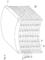
- the process is repeated until the required number of plates is stacked and the mirror plate stack 30 is fully assembled, as illustrated in Fig. 9 .
- the base plate or structural substrate 13, onto which the plates 10 have been stacked, is retained and used as the carrier plate for the optical module used to later to interface the mirror plate stack 30 to the optical bench.
- the bonding of all plates during the integration process, including the first one, is permanent.
- two positive effects are gained: Firstly, only one precision part is required (the optical module back plate 13) in contrast to conventional assembly approaches which require two different precision parts, i.e. the backplane and the optical module structural box. Secondly, the plates 10 are automatically aligned to the optical module structural interfaces upon completion of the plate integration.
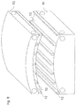
- Fig. 10 illustrates the forming of a Wolter-1 element 35 by aligning two mirror plate stacks 30, 31 using X-ray metrology according to an example being useful for the understanding of the invention.
- two stacks 30, 31 of mirror plates have to be joined together into a tandem configuration.
- the first stack 30 consists of parabolically shaped plates
- the second stack 30 consists of hyperbolically shaped plates.
- the two stacks are mounted via their base-plates 13 to micro-manipulators into a tandem configuration, i.e. one mirror plate stack 31 is aligned after the other mirror plate stack 30 so that one edge and two corners of the first base plate match a respective edge and the two corners of the second base plate.
- the alignment of the two mirror plate stacks 30,31 is critical and one of the most stringent parts of the error budget.
- the longitudinal angle (along the optical axis) defining the kink-angle between the parabola and the hyperbola stacks must be accurate to a small fraction of the required angular resolution of the system.
- This alignment should be conducted with respect to the X-ray effective positions and figures of the plates. This alignment is therefore done in an X-ray facility using on-line X-ray metrology.
- the imaging properties of the stack pair is measured in real time and the alignment performed using micro-positioners (not shown) holding the two plate stacks 30, 31 at their base-plates 13. Once the correct alignment is achieved within the specified tolerances, and this is confirmed by the X-ray metrology, the two stacks 30, 31 are permanently joined via their base-plates 13. The doublet now forms a Wolter-1 X-ray optical unit 35.
- alignment of the two mirror stacks 30, 31 is done using X-ray metrology, the actual performance of the complete system (X-ray optical unit, an Wolter-1 element) is measured in X-rays, and the two stacks 30,31 are accurately aligned with respect to each other.
- the alignment method intrinsically considers all the mirror plates simultaneously, and performs a direct measurement of the optical performance, including the determination of the most critical kink angle (angle between the parabola and hyperbola) to high accuracy and fidelity. In the prior art, this critical alignment between the parabolic and the hyperbolic plate is done at the time of stacking, using visible optical metrology.
- Fig. 11 illustrates an optical unit comprising two mirror plate stacks and interface means for later integration into a telescope system according to an example.
- the final optical unit 40 is obtained, wherein the base-plates 13 form a single structural element, holding two stacks of mirror plates in precise alignment.
- the base plates 13 contain integrated interface elements 36. These interface elements 36 are three rigid fixing means with well defined mechanical attachment holes and surfaces.
- the resulting optical unit 35 is mounted onto a suitable optical bench using isostatic mounts.
Landscapes
- Physics & Mathematics (AREA)
- Spectroscopy & Molecular Physics (AREA)
- Engineering & Computer Science (AREA)
- General Engineering & Computer Science (AREA)
- High Energy & Nuclear Physics (AREA)
- General Physics & Mathematics (AREA)
- Optics & Photonics (AREA)
- Life Sciences & Earth Sciences (AREA)
- Astronomy & Astrophysics (AREA)
- Sustainable Development (AREA)
- Optical Elements Other Than Lenses (AREA)
- Mounting And Adjusting Of Optical Elements (AREA)
- Analysing Materials By The Use Of Radiation (AREA)
Claims (10)
- Procédé d'assemblage d'une pile (30) de plaques-miroirs comprenant une pluralité de plaques-miroirs (10) et une plaque de base (13) sur laquelle est empilée la pluralité de plaques-miroirs, ledit procédé comprenant les étapes consistant à :- munir une plaque de base (13) d'une première plaque-miroir montée sur celle-ci ;- munir un outil de manutention d'une deuxième plaque-miroir ;- disposer un espaceur sur une première surface de la deuxième plaque-miroir ;- positionner l'outil de manutention comprenant la deuxième plaque-miroir avec l'espaceur pour aligner la deuxième plaque-miroir avec la première plaque-miroir, la deuxième plaque-miroir étant alignée par rapport à la première plaque-miroir sur la base de forme et position mesurées de la première plaque-miroir pour compenser un écart des forme et position mesurées de la première plaque-miroir par rapport à des forme et position prédéfinies de la première plaque-miroir ;- fixer la deuxième plaque-miroir à la première plaque-miroir par liaison de l'espaceur à la première plaque-miroir, l'espaceur déterminant une distance prédéfinie entre les première et deuxième plaques-miroirs ;- exposer une seconde surface de la deuxième plaque-miroir par retrait l'outil de manutention de la deuxième plaque-miroir fixée ; etmesurer les position et forme de la deuxième plaque-miroir fixée après que la seconde surface a été exposée, caractérisé par le fait que l'outil de manutention est un mandrin, le procédé comprenant en outre l'étape consistant à mettre en forme la plaque-miroir à une forme prédéfinie au moyen du mandrin.
- Procédé selon la revendication 1, dans lequel les étapes selon la revendication 1 sont répétées pour empiler une pluralité de plaques-miroirs sur la plaque de base de telle sorte qu'au moins une troisième plaque-miroir est fixée à la deuxième plaque-miroir.
- Procédé selon l'une des revendications 1 ou 2, comprenant en outre les étapes suivantes si une première plaque-miroir est la première plaque devant être empilée sur la plaque de base :- disposer la plaque de base (13) ;- munir l'outil de manutention de la première plaque-miroir ;- disposer un espaceur sur une première surface de la première plaque-miroir ;- positionner l'outil de manutention comprenant la première plaque-miroir avec l'espaceur pour aligner la première plaque-miroir avec la plaque de base ;- fixer la première plaque-miroir à la plaque de base par liaison de l'espaceur à la plaque de base ;- exposer une seconde surface de la première plaque-miroir par retrait de l'outil de manutention de la première plaque-miroir fixée ; et- mesurer les position et forme de la première plaque-miroir après que la seconde surface a été exposée.
- Procédé selon au moins une des revendications précédentes, dans lequel les plaques-miroirs sont alignées au moyen de méthodes d'alignement mécaniques et optiques qui utilisent des éléments de référence (14, 15) disposés sur l'outil de manutention et la plaque de base (13).
- Procédé selon au moins une des revendications précédentes, dans lequel la plaque de base sur laquelle ont été empilées les plaques-miroirs est utilisée comme plaque de support pour relier la pile de plaques-miroirs à un banc optique.
- Procédé selon au moins une des revendications précédentes, dans lequel, dans l'étape consistant à mesurer les position et forme de la plaque-miroir fixée après que la seconde surface a été exposée, les position et forme sont mesurées à une précision requise à l'aide d'interférométrie et d'holographie générée par ordinateur.
- Procédé selon au moins une des revendications précédentes, dans lequel les plaques-miroirs sont des plaques-miroirs en verre et le mandrin est un mandrin (11) de thermoformage sur moule pour le verre.
- Procédé selon au moins une des revendications précédentes, comprenant en outre l'étape consistant à fixer de façon amovible la seconde surface de la plaque-miroir à l'outil de manutention au moyen d'une couche de séparation, un coefficient d'adhérence de la couche de séparation étant défini à une valeur pour maintenir la plaque-miroir dans une position fixe pendant l'étape consistant à positionner l'outil de manutention comprenant la plaque-miroir avec le moyen espaceur et, après l'étape consistant à fixer la plaque-miroir, la valeur du coefficient d'adhérence permettant un retrait de l'outil de manutention de la plaque-miroir fixée.
- Procédé selon au moins une des revendications précédentes, dans lequel l'espaceur comprend des nervures d'espacement.
- Procédé selon au moins une des revendications précédentes, dans lequel la plaque de base ou le moyen espaceur est fait d'un même matériau que le matériau des plaques-miroirs.
Priority Applications (8)
| Application Number | Priority Date | Filing Date | Title |
|---|---|---|---|
| EP11163176.8A EP2348348B1 (fr) | 2009-08-28 | 2009-08-28 | Procédé d'assemblage d'une pile à plaque-miroir |
| EP11163175A EP2348347A3 (fr) | 2009-08-28 | 2009-08-28 | Procédé d'assemblage de plusieures piles à plaque-miroir en un ensemble rigide |
| EP09168979.4A EP2290420B1 (fr) | 2009-08-28 | 2009-08-28 | Procédé d'assemblage d'une pile à plaque-miroir |
| US13/392,453 US8746903B2 (en) | 2009-08-28 | 2010-08-27 | Method for assembling a mirror plate stack |
| KR1020127007580A KR20120090995A (ko) | 2009-08-28 | 2010-08-27 | 미러 플레이트 적층체 조립 방법 |
| JP2012525936A JP5567135B2 (ja) | 2009-08-28 | 2010-08-27 | 積層鏡面プレートの組み立て方法 |
| PCT/EP2010/005283 WO2011023403A2 (fr) | 2009-08-28 | 2010-08-27 | Procédé pour l'assemblage d'un empilement de plaques de miroir |
| CN2010800384410A CN102576142A (zh) | 2009-08-28 | 2010-08-27 | 装配镜板叠层的方法 |
Applications Claiming Priority (1)
| Application Number | Priority Date | Filing Date | Title |
|---|---|---|---|
| EP09168979.4A EP2290420B1 (fr) | 2009-08-28 | 2009-08-28 | Procédé d'assemblage d'une pile à plaque-miroir |
Related Child Applications (3)
| Application Number | Title | Priority Date | Filing Date |
|---|---|---|---|
| EP11163176.8A Division-Into EP2348348B1 (fr) | 2009-08-28 | 2009-08-28 | Procédé d'assemblage d'une pile à plaque-miroir |
| EP11163176.8A Division EP2348348B1 (fr) | 2009-08-28 | 2009-08-28 | Procédé d'assemblage d'une pile à plaque-miroir |
| EP11163175A Division-Into EP2348347A3 (fr) | 2009-08-28 | 2009-08-28 | Procédé d'assemblage de plusieures piles à plaque-miroir en un ensemble rigide |
Publications (2)
| Publication Number | Publication Date |
|---|---|
| EP2290420A1 EP2290420A1 (fr) | 2011-03-02 |
| EP2290420B1 true EP2290420B1 (fr) | 2016-07-27 |
Family
ID=41278291
Family Applications (3)
| Application Number | Title | Priority Date | Filing Date |
|---|---|---|---|
| EP11163176.8A Not-in-force EP2348348B1 (fr) | 2009-08-28 | 2009-08-28 | Procédé d'assemblage d'une pile à plaque-miroir |
| EP11163175A Withdrawn EP2348347A3 (fr) | 2009-08-28 | 2009-08-28 | Procédé d'assemblage de plusieures piles à plaque-miroir en un ensemble rigide |
| EP09168979.4A Not-in-force EP2290420B1 (fr) | 2009-08-28 | 2009-08-28 | Procédé d'assemblage d'une pile à plaque-miroir |
Family Applications Before (2)
| Application Number | Title | Priority Date | Filing Date |
|---|---|---|---|
| EP11163176.8A Not-in-force EP2348348B1 (fr) | 2009-08-28 | 2009-08-28 | Procédé d'assemblage d'une pile à plaque-miroir |
| EP11163175A Withdrawn EP2348347A3 (fr) | 2009-08-28 | 2009-08-28 | Procédé d'assemblage de plusieures piles à plaque-miroir en un ensemble rigide |
Country Status (6)
| Country | Link |
|---|---|
| US (1) | US8746903B2 (fr) |
| EP (3) | EP2348348B1 (fr) |
| JP (1) | JP5567135B2 (fr) |
| KR (1) | KR20120090995A (fr) |
| CN (1) | CN102576142A (fr) |
| WO (1) | WO2011023403A2 (fr) |
Families Citing this family (6)
| Publication number | Priority date | Publication date | Assignee | Title |
|---|---|---|---|---|
| CN107847200B (zh) * | 2015-07-14 | 2022-04-01 | 皇家飞利浦有限公司 | 利用增强的x射线辐射的成像装置和系统 |
| EP3441764B1 (fr) | 2016-04-05 | 2021-01-27 | ARKRAY, Inc. | Procédé de détermination de stade de maladie parodontale |
| RU2629693C1 (ru) * | 2016-10-13 | 2017-08-31 | Федеральное государственное унитарное предприятие "Российский Федеральный ядерный центр - Всероссийский научно-исследовательский институт экспериментальной физики" (ФГУП "РФЯЦ-ВНИИЭФ") | Способ сборки рентгеновской оптической системы, содержащей n зеркальных модулей |
| US11398359B2 (en) | 2018-12-26 | 2022-07-26 | Apple Inc. | Transparent keycaps |
| EP3745420A1 (fr) * | 2019-05-27 | 2020-12-02 | Koninklijke Philips N.V. | Structures de réseau stabilisées |
| US11217357B2 (en) * | 2020-02-10 | 2022-01-04 | Sigray, Inc. | X-ray mirror optics with multiple hyperboloidal/hyperbolic surface profiles |
Family Cites Families (26)
| Publication number | Priority date | Publication date | Assignee | Title |
|---|---|---|---|---|
| US2135873A (en) * | 1934-11-22 | 1938-11-08 | Bausch & Lomb | Process of making metal reflectors |
| US5523815A (en) * | 1993-05-18 | 1996-06-04 | Konica Corporation | Light amount control unit |
| US5532815A (en) * | 1994-06-17 | 1996-07-02 | Kdy Associates, Inc. | System and method for aligning a first surface with respect to a second surface |
| JPH08146197A (ja) | 1994-11-15 | 1996-06-07 | Nikon Corp | 反射鏡固定方法及び反射鏡ホルダー |
| FR2788348B1 (fr) | 1999-01-07 | 2001-03-02 | Agence Spatiale Europeenne | Procede d'assemblage d'un ensemble optique comprenant des coquilles coaxiales, notamment pour telescope a rayon x |
| TW561279B (en) * | 1999-07-02 | 2003-11-11 | Asml Netherlands Bv | Reflector for reflecting radiation in a desired wavelength range, lithographic projection apparatus containing the same and method for their preparation |
| US6278764B1 (en) | 1999-07-22 | 2001-08-21 | The Regents Of The Unviersity Of California | High efficiency replicated x-ray optics and fabrication method |
| US6137579A (en) * | 1999-08-20 | 2000-10-24 | Reilley; Peter | Planar alignment system and method |
| GB9927555D0 (en) * | 1999-11-23 | 2000-01-19 | Bede Scient Instr Ltd | X-ray fluorescence apparatus |
| US7077532B1 (en) * | 2000-04-05 | 2006-07-18 | Sandia Corporation | Solar reflection panels |
| US7347572B1 (en) * | 2000-05-23 | 2008-03-25 | Media Lario S.R.L. | Telescope mirror for high bandwidth free space optical data transmission |
| US6533426B2 (en) * | 2001-05-02 | 2003-03-18 | The United States Of America As Represented By The Secretary Of The Air Force | Method of centrifugally casting a parabolic membrane mirror having a shape-restorative force |
| US6949748B2 (en) | 2002-04-16 | 2005-09-27 | The Regents Of The University Of California | Biomedical nuclear and X-ray imager using high-energy grazing incidence mirrors |
| US20040032931A1 (en) * | 2002-08-13 | 2004-02-19 | International Business Machines Corporation | X-ray alignment system for fabricaing electronic chips |
| US7268945B2 (en) * | 2002-10-10 | 2007-09-11 | Xradia, Inc. | Short wavelength metrology imaging system |
| JP4068496B2 (ja) * | 2003-04-14 | 2008-03-26 | Nec東芝スペースシステム株式会社 | 鏡面母材及びそれを用いた鏡体及び、鏡体を用いた光学装置 |
| JP2005083862A (ja) * | 2003-09-08 | 2005-03-31 | Canon Inc | 光学薄膜およびこれを用いたミラー |
| FR2866438B1 (fr) * | 2004-02-16 | 2006-08-11 | Agence Spatiale Europeenne | Element optique reflecteur, son procede de fabrication, et instrument optique mettant en oeuvre de tels elements |
| DE102004026357B4 (de) * | 2004-05-26 | 2022-11-17 | Werth Messtechnik Gmbh | Vorrichtung und Verfahren zum Messen eines Objektes |
| WO2007003359A1 (fr) * | 2005-07-01 | 2007-01-11 | Carl Zeiss Smt Ag | Unite de collecteur destinee a un systeme d'eclairage ayant des longueurs d'onde = 193 nm |
| US7334947B2 (en) * | 2005-10-24 | 2008-02-26 | Ondine International Ltd | Alignment system and method |
| US7519153B1 (en) | 2006-03-24 | 2009-04-14 | Kla-Tencor Technologies Corporation | X-ray metrology with diffractors |
| US7481579B2 (en) * | 2006-03-27 | 2009-01-27 | Jordan Valley Applied Radiation Ltd. | Overlay metrology using X-rays |
| JP4682082B2 (ja) | 2006-03-31 | 2011-05-11 | 株式会社ジェイテック | X線集光装置 |
| KR100781309B1 (ko) * | 2006-04-24 | 2007-12-03 | 원광대학교산학협력단 | 엑스선 미러복제코어 및 그 미러복제코어를 이용한 엑스선미러 복제 방법 |
| EP2249704A4 (fr) * | 2008-01-30 | 2013-07-03 | Reflective X Ray Optics Llc | Monture de miroir, mécanisme d'alignement et de balayage, procédé de balayage pour imagerie radiographique par rayons x, et dispositif d'imagerie par rayons x comportant ces éléments |
-
2009
- 2009-08-28 EP EP11163176.8A patent/EP2348348B1/fr not_active Not-in-force
- 2009-08-28 EP EP11163175A patent/EP2348347A3/fr not_active Withdrawn
- 2009-08-28 EP EP09168979.4A patent/EP2290420B1/fr not_active Not-in-force
-
2010
- 2010-08-27 JP JP2012525936A patent/JP5567135B2/ja not_active Expired - Fee Related
- 2010-08-27 KR KR1020127007580A patent/KR20120090995A/ko not_active Application Discontinuation
- 2010-08-27 WO PCT/EP2010/005283 patent/WO2011023403A2/fr active Application Filing
- 2010-08-27 US US13/392,453 patent/US8746903B2/en not_active Expired - Fee Related
- 2010-08-27 CN CN2010800384410A patent/CN102576142A/zh active Pending
Non-Patent Citations (1)
| Title |
|---|
| MARCO BEIJERSBERGEN ET AL: "Development of x-ray pore optics: novel high-resolution silicon millipore optics for XEUS and ultralow mass glass micropore optics for imaging and timing", PROCEEDINGS OF SPIE, vol. 5539, 4 November 2004 (2004-11-04), US, pages 104 - 115, XP055228243, ISSN: 0277-786X, ISBN: 978-1-62841-839-2, DOI: 10.1117/12.552942 * |
Also Published As
| Publication number | Publication date |
|---|---|
| CN102576142A (zh) | 2012-07-11 |
| JP2013503324A (ja) | 2013-01-31 |
| EP2348347A3 (fr) | 2012-07-04 |
| EP2290420A1 (fr) | 2011-03-02 |
| EP2348348A3 (fr) | 2012-08-08 |
| JP5567135B2 (ja) | 2014-08-06 |
| US8746903B2 (en) | 2014-06-10 |
| US20120182634A1 (en) | 2012-07-19 |
| WO2011023403A3 (fr) | 2011-05-26 |
| WO2011023403A2 (fr) | 2011-03-03 |
| EP2348347A2 (fr) | 2011-07-27 |
| EP2348348A2 (fr) | 2011-07-27 |
| EP2348348B1 (fr) | 2014-11-19 |
| KR20120090995A (ko) | 2012-08-17 |
Similar Documents
| Publication | Publication Date | Title |
|---|---|---|
| Beijersbergen et al. | Silicon pore optics: novel lightweight high-resolution X-ray optics developed for XEUS | |
| EP2290420B1 (fr) | Procédé d'assemblage d'une pile à plaque-miroir | |
| Civitani et al. | IXO x-ray mirrors based on slumped glass segments with reinforcing ribs: optical and mechanical design, image error budget, and optics unit integration process | |
| Zhang et al. | Monocrystalline silicon and the meta-shell approach to building x-ray astronomical optics | |
| Zhang et al. | High resolution and high throughput x-ray optics for future astronomical missions | |
| Pareschi et al. | IXO glass mirrors development in Europe | |
| TWI245971B (en) | Lithographic apparatus and device manufacturing method | |
| Chan et al. | Alignment and bonding of silicon mirrors for high-resolution astronomical x-ray optics | |
| Döhring et al. | Development of low-stress Iridium coatings for astronomical x-ray mirrors | |
| Collon et al. | Stacking of silicon pore optics for IXO | |
| Kraft et al. | Development of modular high-performance pore optics for the XEUS x-ray telescope | |
| Civitani et al. | An integration machine for the assembly of the x-ray optic units based on thin slumped glass foils for the IXO mission | |
| Collon et al. | Performance characterization of silicon pore optics | |
| Bavdaz et al. | X-ray optics developments at ESA | |
| Collon et al. | Aberration-free silicon pore x-ray optics | |
| Ghigo et al. | Development of high angular resolution x-ray telescopes based on slumped glass foils | |
| Ghigo et al. | Hot slumping glass technology and integration process to manufacture a grazing incidence scaled prototype for the IXO telescope modules | |
| Chan et al. | Kinematic alignment and bonding of silicon mirrors for high-resolution astronomical x-ray optics | |
| Spiga et al. | Manufacturing an active X-ray mirror prototype in thin glass | |
| Wang et al. | Development of imaging x-ray telescopes at Tongji University | |
| Collon et al. | X-ray imaging glass micro-pore optics | |
| Collon et al. | Silicon pore optics for astrophysical x-ray missions | |
| Civitani et al. | Slumped glass optics with interfacing ribs for high angular resolution x-ray astronomy: a progress report | |
| Civitani et al. | Cold shaping of thin glass foils: a fast and cost-effective solution for making light-weight astronomical x-ray optics | |
| Proserpio et al. | JIM: a joint integrated module of glass x-ray optics for astronomical telescopes |
Legal Events
| Date | Code | Title | Description |
|---|---|---|---|
| PUAI | Public reference made under article 153(3) epc to a published international application that has entered the european phase |
Free format text: ORIGINAL CODE: 0009012 |
|
| AK | Designated contracting states |
Kind code of ref document: A1 Designated state(s): AT BE BG CH CY CZ DE DK EE ES FI FR GB GR HR HU IE IS IT LI LT LU LV MC MK MT NL NO PL PT RO SE SI SK SM TR |
|
| AX | Request for extension of the european patent |
Extension state: AL BA RS |
|
| 17P | Request for examination filed |
Effective date: 20110902 |
|
| 17Q | First examination report despatched |
Effective date: 20140401 |
|
| REG | Reference to a national code |
Ref country code: DE Ref legal event code: R079 Ref document number: 602009039933 Country of ref document: DE Free format text: PREVIOUS MAIN CLASS: G02B0007182000 Ipc: G21K0001060000 |
|
| GRAP | Despatch of communication of intention to grant a patent |
Free format text: ORIGINAL CODE: EPIDOSNIGR1 |
|
| RIC1 | Information provided on ipc code assigned before grant |
Ipc: G21K 1/06 20060101AFI20151118BHEP |
|
| INTG | Intention to grant announced |
Effective date: 20151210 |
|
| GRAS | Grant fee paid |
Free format text: ORIGINAL CODE: EPIDOSNIGR3 |
|
| RIN1 | Information on inventor provided before grant (corrected) |
Inventor name: BAVDAZ, MARCOS |
|
| GRAP | Despatch of communication of intention to grant a patent |
Free format text: ORIGINAL CODE: EPIDOSNIGR1 |
|
| GRAA | (expected) grant |
Free format text: ORIGINAL CODE: 0009210 |
|
| INTG | Intention to grant announced |
Effective date: 20160603 |
|
| AK | Designated contracting states |
Kind code of ref document: B1 Designated state(s): AT BE BG CH CY CZ DE DK EE ES FI FR GB GR HR HU IE IS IT LI LT LU LV MC MK MT NL NO PL PT RO SE SI SK SM TR |
|
| REG | Reference to a national code |
Ref country code: GB Ref legal event code: FG4D |
|
| REG | Reference to a national code |
Ref country code: CH Ref legal event code: EP |
|
| REG | Reference to a national code |
Ref country code: AT Ref legal event code: REF Ref document number: 816375 Country of ref document: AT Kind code of ref document: T Effective date: 20160815 |
|
| REG | Reference to a national code |
Ref country code: IE Ref legal event code: FG4D |
|
| REG | Reference to a national code |
Ref country code: DE Ref legal event code: R096 Ref document number: 602009039933 Country of ref document: DE |
|
| REG | Reference to a national code |
Ref country code: LT Ref legal event code: MG4D |
|
| REG | Reference to a national code |
Ref country code: NL Ref legal event code: MP Effective date: 20160727 |
|
| REG | Reference to a national code |
Ref country code: AT Ref legal event code: MK05 Ref document number: 816375 Country of ref document: AT Kind code of ref document: T Effective date: 20160727 |
|
| PG25 | Lapsed in a contracting state [announced via postgrant information from national office to epo] |
Ref country code: BE Free format text: LAPSE BECAUSE OF NON-PAYMENT OF DUE FEES Effective date: 20160831 |
|
| PG25 | Lapsed in a contracting state [announced via postgrant information from national office to epo] |
Ref country code: IS Free format text: LAPSE BECAUSE OF FAILURE TO SUBMIT A TRANSLATION OF THE DESCRIPTION OR TO PAY THE FEE WITHIN THE PRESCRIBED TIME-LIMIT Effective date: 20161127 Ref country code: LT Free format text: LAPSE BECAUSE OF FAILURE TO SUBMIT A TRANSLATION OF THE DESCRIPTION OR TO PAY THE FEE WITHIN THE PRESCRIBED TIME-LIMIT Effective date: 20160727 Ref country code: HR Free format text: LAPSE BECAUSE OF FAILURE TO SUBMIT A TRANSLATION OF THE DESCRIPTION OR TO PAY THE FEE WITHIN THE PRESCRIBED TIME-LIMIT Effective date: 20160727 Ref country code: FI Free format text: LAPSE BECAUSE OF FAILURE TO SUBMIT A TRANSLATION OF THE DESCRIPTION OR TO PAY THE FEE WITHIN THE PRESCRIBED TIME-LIMIT Effective date: 20160727 Ref country code: NO Free format text: LAPSE BECAUSE OF FAILURE TO SUBMIT A TRANSLATION OF THE DESCRIPTION OR TO PAY THE FEE WITHIN THE PRESCRIBED TIME-LIMIT Effective date: 20161027 Ref country code: NL Free format text: LAPSE BECAUSE OF FAILURE TO SUBMIT A TRANSLATION OF THE DESCRIPTION OR TO PAY THE FEE WITHIN THE PRESCRIBED TIME-LIMIT Effective date: 20160727 |
|
| PG25 | Lapsed in a contracting state [announced via postgrant information from national office to epo] |
Ref country code: GR Free format text: LAPSE BECAUSE OF FAILURE TO SUBMIT A TRANSLATION OF THE DESCRIPTION OR TO PAY THE FEE WITHIN THE PRESCRIBED TIME-LIMIT Effective date: 20161028 Ref country code: LV Free format text: LAPSE BECAUSE OF FAILURE TO SUBMIT A TRANSLATION OF THE DESCRIPTION OR TO PAY THE FEE WITHIN THE PRESCRIBED TIME-LIMIT Effective date: 20160727 Ref country code: ES Free format text: LAPSE BECAUSE OF FAILURE TO SUBMIT A TRANSLATION OF THE DESCRIPTION OR TO PAY THE FEE WITHIN THE PRESCRIBED TIME-LIMIT Effective date: 20160727 Ref country code: PT Free format text: LAPSE BECAUSE OF FAILURE TO SUBMIT A TRANSLATION OF THE DESCRIPTION OR TO PAY THE FEE WITHIN THE PRESCRIBED TIME-LIMIT Effective date: 20161128 Ref country code: PL Free format text: LAPSE BECAUSE OF FAILURE TO SUBMIT A TRANSLATION OF THE DESCRIPTION OR TO PAY THE FEE WITHIN THE PRESCRIBED TIME-LIMIT Effective date: 20160727 Ref country code: SE Free format text: LAPSE BECAUSE OF FAILURE TO SUBMIT A TRANSLATION OF THE DESCRIPTION OR TO PAY THE FEE WITHIN THE PRESCRIBED TIME-LIMIT Effective date: 20160727 Ref country code: BE Free format text: LAPSE BECAUSE OF FAILURE TO SUBMIT A TRANSLATION OF THE DESCRIPTION OR TO PAY THE FEE WITHIN THE PRESCRIBED TIME-LIMIT Effective date: 20160727 Ref country code: AT Free format text: LAPSE BECAUSE OF FAILURE TO SUBMIT A TRANSLATION OF THE DESCRIPTION OR TO PAY THE FEE WITHIN THE PRESCRIBED TIME-LIMIT Effective date: 20160727 |
|
| REG | Reference to a national code |
Ref country code: DE Ref legal event code: R119 Ref document number: 602009039933 Country of ref document: DE |
|
| REG | Reference to a national code |
Ref country code: CH Ref legal event code: PL |
|
| PG25 | Lapsed in a contracting state [announced via postgrant information from national office to epo] |
Ref country code: LI Free format text: LAPSE BECAUSE OF NON-PAYMENT OF DUE FEES Effective date: 20160831 Ref country code: RO Free format text: LAPSE BECAUSE OF FAILURE TO SUBMIT A TRANSLATION OF THE DESCRIPTION OR TO PAY THE FEE WITHIN THE PRESCRIBED TIME-LIMIT Effective date: 20160727 Ref country code: EE Free format text: LAPSE BECAUSE OF FAILURE TO SUBMIT A TRANSLATION OF THE DESCRIPTION OR TO PAY THE FEE WITHIN THE PRESCRIBED TIME-LIMIT Effective date: 20160727 Ref country code: MC Free format text: LAPSE BECAUSE OF FAILURE TO SUBMIT A TRANSLATION OF THE DESCRIPTION OR TO PAY THE FEE WITHIN THE PRESCRIBED TIME-LIMIT Effective date: 20160727 Ref country code: CH Free format text: LAPSE BECAUSE OF NON-PAYMENT OF DUE FEES Effective date: 20160831 |
|
| PG25 | Lapsed in a contracting state [announced via postgrant information from national office to epo] |
Ref country code: SK Free format text: LAPSE BECAUSE OF FAILURE TO SUBMIT A TRANSLATION OF THE DESCRIPTION OR TO PAY THE FEE WITHIN THE PRESCRIBED TIME-LIMIT Effective date: 20160727 Ref country code: SM Free format text: LAPSE BECAUSE OF FAILURE TO SUBMIT A TRANSLATION OF THE DESCRIPTION OR TO PAY THE FEE WITHIN THE PRESCRIBED TIME-LIMIT Effective date: 20160727 Ref country code: BG Free format text: LAPSE BECAUSE OF FAILURE TO SUBMIT A TRANSLATION OF THE DESCRIPTION OR TO PAY THE FEE WITHIN THE PRESCRIBED TIME-LIMIT Effective date: 20161027 Ref country code: DK Free format text: LAPSE BECAUSE OF FAILURE TO SUBMIT A TRANSLATION OF THE DESCRIPTION OR TO PAY THE FEE WITHIN THE PRESCRIBED TIME-LIMIT Effective date: 20160727 Ref country code: CZ Free format text: LAPSE BECAUSE OF FAILURE TO SUBMIT A TRANSLATION OF THE DESCRIPTION OR TO PAY THE FEE WITHIN THE PRESCRIBED TIME-LIMIT Effective date: 20160727 |
|
| REG | Reference to a national code |
Ref country code: IE Ref legal event code: MM4A |
|
| PLBE | No opposition filed within time limit |
Free format text: ORIGINAL CODE: 0009261 |
|
| STAA | Information on the status of an ep patent application or granted ep patent |
Free format text: STATUS: NO OPPOSITION FILED WITHIN TIME LIMIT |
|
| GBPC | Gb: european patent ceased through non-payment of renewal fee |
Effective date: 20161027 |
|
| 26N | No opposition filed |
Effective date: 20170502 |
|
| REG | Reference to a national code |
Ref country code: FR Ref legal event code: ST Effective date: 20170602 |
|
| PG25 | Lapsed in a contracting state [announced via postgrant information from national office to epo] |
Ref country code: DE Free format text: LAPSE BECAUSE OF NON-PAYMENT OF DUE FEES Effective date: 20170301 Ref country code: IE Free format text: LAPSE BECAUSE OF NON-PAYMENT OF DUE FEES Effective date: 20160828 Ref country code: FR Free format text: LAPSE BECAUSE OF NON-PAYMENT OF DUE FEES Effective date: 20160927 Ref country code: GB Free format text: LAPSE BECAUSE OF NON-PAYMENT OF DUE FEES Effective date: 20161027 |
|
| PG25 | Lapsed in a contracting state [announced via postgrant information from national office to epo] |
Ref country code: LU Free format text: LAPSE BECAUSE OF NON-PAYMENT OF DUE FEES Effective date: 20160828 Ref country code: SI Free format text: LAPSE BECAUSE OF FAILURE TO SUBMIT A TRANSLATION OF THE DESCRIPTION OR TO PAY THE FEE WITHIN THE PRESCRIBED TIME-LIMIT Effective date: 20160727 |
|
| PG25 | Lapsed in a contracting state [announced via postgrant information from national office to epo] |
Ref country code: HU Free format text: LAPSE BECAUSE OF FAILURE TO SUBMIT A TRANSLATION OF THE DESCRIPTION OR TO PAY THE FEE WITHIN THE PRESCRIBED TIME-LIMIT; INVALID AB INITIO Effective date: 20090828 Ref country code: CY Free format text: LAPSE BECAUSE OF FAILURE TO SUBMIT A TRANSLATION OF THE DESCRIPTION OR TO PAY THE FEE WITHIN THE PRESCRIBED TIME-LIMIT Effective date: 20160727 |
|
| PG25 | Lapsed in a contracting state [announced via postgrant information from national office to epo] |
Ref country code: MK Free format text: LAPSE BECAUSE OF FAILURE TO SUBMIT A TRANSLATION OF THE DESCRIPTION OR TO PAY THE FEE WITHIN THE PRESCRIBED TIME-LIMIT Effective date: 20160727 Ref country code: MT Free format text: LAPSE BECAUSE OF NON-PAYMENT OF DUE FEES Effective date: 20160831 Ref country code: TR Free format text: LAPSE BECAUSE OF FAILURE TO SUBMIT A TRANSLATION OF THE DESCRIPTION OR TO PAY THE FEE WITHIN THE PRESCRIBED TIME-LIMIT Effective date: 20160727 |
|
| PGFP | Annual fee paid to national office [announced via postgrant information from national office to epo] |
Ref country code: IT Payment date: 20180830 Year of fee payment: 10 |
|
| PG25 | Lapsed in a contracting state [announced via postgrant information from national office to epo] |
Ref country code: IT Free format text: LAPSE BECAUSE OF NON-PAYMENT OF DUE FEES Effective date: 20190828 |