EP2289791A1 - Motorcycle - Google Patents
Motorcycle Download PDFInfo
- Publication number
- EP2289791A1 EP2289791A1 EP10174691A EP10174691A EP2289791A1 EP 2289791 A1 EP2289791 A1 EP 2289791A1 EP 10174691 A EP10174691 A EP 10174691A EP 10174691 A EP10174691 A EP 10174691A EP 2289791 A1 EP2289791 A1 EP 2289791A1
- Authority
- EP
- European Patent Office
- Prior art keywords
- gear
- gear housing
- shaft
- motorcycle
- swing arm
- Prior art date
- Legal status (The legal status is an assumption and is not a legal conclusion. Google has not performed a legal analysis and makes no representation as to the accuracy of the status listed.)
- Granted
Links
Images







Classifications
-
- B—PERFORMING OPERATIONS; TRANSPORTING
- B62—LAND VEHICLES FOR TRAVELLING OTHERWISE THAN ON RAILS
- B62M—RIDER PROPULSION OF WHEELED VEHICLES OR SLEDGES; POWERED PROPULSION OF SLEDGES OR SINGLE-TRACK CYCLES; TRANSMISSIONS SPECIALLY ADAPTED FOR SUCH VEHICLES
- B62M17/00—Transmissions characterised by use of rotary shaft, e.g. cardan shaft
-
- B—PERFORMING OPERATIONS; TRANSPORTING
- B62—LAND VEHICLES FOR TRAVELLING OTHERWISE THAN ON RAILS
- B62M—RIDER PROPULSION OF WHEELED VEHICLES OR SLEDGES; POWERED PROPULSION OF SLEDGES OR SINGLE-TRACK CYCLES; TRANSMISSIONS SPECIALLY ADAPTED FOR SUCH VEHICLES
- B62M7/00—Motorcycles characterised by position of motor or engine
- B62M7/02—Motorcycles characterised by position of motor or engine with engine between front and rear wheels
- B62M7/04—Motorcycles characterised by position of motor or engine with engine between front and rear wheels below the frame
Definitions
- the present invention relates to motorcycles, and more specifically to a shaft drive motorcycle.
- JP 09-72927 A discloses a motorcycle that employs a shaft drive power transmission mechanism for secondary transmission of power from a transmission to a rear wheel (see paragraphs 0008 to 0015 and Figs. 1 to 5 ).
- the motorcycle includes a rear fork, a drive shaft, a gear case, and a rear bevel gear.
- the left part of the rear fork also serves as a tubular casing used to store a part of the drive shaft.
- the rear end of the rear fork is connected to the gear case.
- the gear case stores the rear bevel gear.
- the rear bevel gear includes a first rear gear incorporated at the rear end of the drive shaft and a second rear gear provided rotatably in the gear case.
- the drive shaft is coupled to the hub of the rear wheel through the rear bevel gear.
- the second rear gear has a relatively thin disk shape.
- the second rear gear is coaxial with the axle shaft of the rear wheel and arranged to rotate together with the rear wheel.
- JP 2008-87585 A discloses a motorcycle in which the power of an output shaft included in an engine unit provided at a vehicle body frame is transmitted to the rear wheel side through a rear wheel drive shaft (see paragraphs 0014 to 0027 and Figs. 1 to 5 ).
- the motorcycle includes a rear wheel suspension device, a rear wheel drive shaft, a bevel gear mechanism, and a hypoid gear.
- the rear wheel suspension device includes an upper arm member, a lower arm member, a knuckle member, and a rear cushion unit.
- a rear wheel support provided on the left side of the rear wheel in the knuckle member is provided as a gear housing.
- the rear drive shaft includes four shaft members.
- the front end of a first shaft member is coupled to the output shaft of the engine through the bevel gear mechanism.
- the front end of a second shaft member is coupled to the rear end of the first shaft member through a first universal joint.
- a Neithard mechanism is provided between the second shaft member and a third shaft member.
- the front end of a fourth shaft member is coupled to the rear end of the third shaft member through a second universal joint.
- the fourth shaft member is entered into the rear wheel support so that the axial line of the fourth shaft member passes a position offset from the rotation axial line of the rear wheel.
- the axial line of the fourth shaft member is offset to the upper side from the rotation axial line of the rear wheel.
- the hypoid gear includes a transmission gear and a ring gear.
- the ring gear is stored in the rear wheel support and fixed coaxially with the rear wheel.
- the transmission gear is fixed to the rear end of the fourth shaft member and engaged with the rear gear.
- JP 2008-87585 A discloses a motorcycle in a different form from the above-disclosed motorcycle (see paragraphs 0037 to 0038 and Fig. 6 ).
- the first shaft member is coupled to the output shaft of an engine unit through a hypoid gear mechanism.
- the axial line of the fourth shaft member is provided as it is offset to the lower side from the rotation axial line of the rear wheel.
- the second rear gear has a large diameter and the gear case has an increased size.
- the hypoid gear disclosed by JP 2008-87585 includes a ring gear with a small diameter and quietness in operation, but sliding is generated in engagement between the gears, which should generate power transmission loss.
- the inventors have studied the possibility of reducing the size of the gear housing by employing a hypoid gear unit in which the rotation axis of the pinion gear is offset downward from the rotation center of the ring gear.
- the rotation axis of a transmission gear (pinion gear) is offset downward from the rotation center of the ring gear.
- the gear housing makes parallel translation in the vertical direction in the same position (inclination), and therefore the amount of lubricant oil must be increased in consideration of lubrication of the pinion gear. With the increased lubricant oil, the stirring loss of the lubricant oil by the ring gear increases, which increases power transmission loss by the hypoid gear.
- the inventors have found that in consideration of the power transmission loss caused by the sliding in the engagement of the gears, the hypoid gear disclosed by JP 2008-87585 causes large power transmission loss.
- the inventors have found that the temperature of the gear housing is raised when the size of the gear housing is reduced in the hypoid gear disclosed by JP 2008-87585 A .
- the inventors have also found that the increase in the temperature of the gear housing is also attributable to increase in the temperature of the lubricant oil.
- the inventors have then found that the temperature of the lubricant oil is raised because the gears slide much, which tends to increase the oil temperature more easily than the bevel gear and in addition that the amount of heat dissipation is reduced when the gear housing is reduced in size.
- a motorcycle according to a preferred embodiment of the present invention includes a vehicle body frame, an engine, a swing arm, a rear wheel, a drive shaft, a gear housing, a pinion gear, and a ring gear.
- the vehicle body frame has a pivot shaft.
- the engine is supported at the vehicle body frame.
- the swing arm is provided swingably around the pivot shaft.
- the rear wheel is provided rotatably with the swing arm.
- the first drive shaft is provided to swing together with the swing arm to drive the rear wheel.
- the gear housing is provided integrally with the swing arm to swing around the pivot shaft together with the swing arm.
- the pinion gear is stored in the gear housing and coupled coaxially with the rear end of the first drive shaft.
- the ring gear is stored in the gear housing, coupled coaxially with the axle shaft of the rear wheel, and engaged with the pinion gear.
- the rotation axis of the pinion gear is offset downward from the rotation center of the ring gear.
- the gear housing Since a hypoid gear is employed according to the preferred embodiment of the invention, in which the rotation axis of the pinion gear is offset downward from the rotation center of the ring gear, the gear housing has a reduced size.
- the gear housing is provided integrally with the swing arm and swings together with the swing arm around the pivot shaft, so that even if the amount of the lubricant oil in the gear housing is small, the lubricant oil is supplied sufficiently to the pinion gear and the ring gear. Consequently, according to the present invention, increase in the transmission loss can be restrained while the gear housing is reduced in size.
- the x-direction refers to the front-back direction of the vehicle body
- the y-direction refers to the widthwise direction of the vehicle body
- the z-direction refers to the up-down direction of the vehicle body.
- the front-back direction, the widthwise direction, and the up-down direction of the vehicle body are orthogonal to one another.
- the vehicle front-back and widthwise directions are both horizontal and the up-down direction is the vertical direction.
- the "front,” “back,” “right,” and “left” refer to these directions seen from a rider seated on the motorcycle 1. Therefore, the left in Fig. 1 indicates the front of the motorcycle 1.
- the motorcycle 1 includes a vehicle body frame 3.
- the vehicle body frame 3 includes an engine 5, a fuel tank 7, and a seat 9.
- the engine 5 is provided under the vehicle body frame 3.
- the fuel tank 7 is provided above the vehicle body frame 3 and closer to the front.
- the seat 9 is provided above the vehicle body frame 3 and closer to the back.
- a center stand 13 is provided rotatably under the vehicle body frame 3. When the center stand 13 is upright, the rear wheel 11 is lifted off from the ground surface.
- a head pipe 15 is fixed to the rear end of the vehicle body frame 3.
- the head pipe 15 supports a steering shaft (not shown) around the axial center rotatably.
- a front fork 19 is coupled to the steering shaft through a handle crown 17 and an under bracket 18.
- a front wheel 21 is supported rotatably under the front fork 19.
- a handle 22 is coupled to the steering shaft through the handle crown 17.
- a swing arm 23 is supported at the rear end of the vehicle body frame 3 swingably around a pivot shaft 25.
- the swing arm 23 has a right swing arm 23R (see Fig. 2 ) that extends from the pivot shaft 25 to the right of the rear wheel 11 and a left swing arm 23L that extends from the pivot shaft 25 to the left of the rear wheel 11.
- the swing arm 23 is coupled to the vehicle body frame 3 by a rear suspension mechanism 27.
- the rear suspension mechanism 27 is a so-called bottom link suspension and includes a shock absorber 27a and links 27b and 27c.
- the rear suspension mechanism 27 absorbs impact from the road surface.
- the left swing arm 23L supports the gear housing 31.
- the gear housing 31 is fixed to the rear end of the left swing arm 23L and swings together with the left swing arm 23L around the pivot shaft 25.
- the gear housing 31 and the right swing arm 23R support the axle shaft 33 for the rear shaft 11.
- One end of the axle shaft 33 is coupled to the gear housing 31.
- the other end of the axle shaft 33 is coupled to the rear end of the right swing arm 23R. Therefore, the axle shaft 33 swings together with the swing arm 23.
- the axle shaft 33 supports the single rear wheel 11 rotatably.
- the rear wheel 11 is provided only on the right side of the gear housing 31 and nothing is provided on the left side of the gear housing 31.
- the axle shaft 33 supports a disk brake unit 34 between the rear wheel 11 and the right swing arm 23R.
- the engine 5 includes a crankcase 35.
- the crankcase 35 includes a crankshaft, a transmission, and an output shaft 37.
- the output shaft 37 is provided at the rear portion of the crankcase 35 substantially parallel to the vehicle widthwise direction.
- the output shaft 37 rotates around its axial center by power generated by the engine 5.
- a shaft drive mechanism 41 is coupled to the output shaft 37 through a middle gear unit 39.
- the middle gear unit 39 is a bevel gear unit and includes a driving bevel gear 39a and a driven bevel gear 39b.
- the driving bevel gear 39a is coupled coaxially with the output shaft 37.
- the driven bevel gear 39b is coupled to the front end of the shaft drive mechanism 41.
- the rotation shaft A2 of the driven bevel gear 39b is provided substantially at the same height as the rotation shaft A3 of the driving bevel gear 39a. Power is transmitted from the output shaft 37 to the shaft drive mechanism 41 through the middle gear unit 39 having the above-described structure.
- the rear gear unit 43 is coupled to the rear end portion of the shaft drive mechanism 41.
- the rear gear unit 43 is stored in the gear housing 31.
- the rear gear unit 43 has a small diameter pinion gear 45 and a large diameter ring gear 47 that are engaged with each other.
- the rotation axis A1 of the pinion gear 45 is offset downward from the rotation center P of the ring gear 47.
- the pinion gear 45 is coupled to the rear end of the shaft drive mechanism 41.
- the ring gear 47 is coupled to a hub clutch member 49 by spline coupling at the outer portion of the gear housing 31.
- the hub clutch member 49 is held rotatably at the axle shaft 33 by a ball bearing 50 and rotates together with the ring gear 47.
- a rubber damper 51 is fixed to the hub clutch member 49.
- the rear wheel 11 includes a cast wheel 53 and a tire 55. However, the rear wheel may include a spoke wheel.
- the cast wheel 53 is held rotatably at the axle shaft 33 by two ball bearings 57 and 58.
- the rubber damper 51 is pressed against the hub 53a of the cast wheel 53 and the rubber damper 51 is in surface-contact with the hub 53a. In this way, power is transmitted between the rubber damper 51 and the hub 53a while impact is absorbed.
- the ring gear 47 is coupled to the rear wheel 11 through the hub clutch member 49 and the rubber damper 51. Therefore, the ring gear 47 rotates together with the rear wheel 11.
- the rear gear unit 43 (the pinion gear 5 and the ring gear 47) lowers the rotation speed of the shaft drive mechanism 41 while changing the rotation direction of the shaft drive mechanism 41 by about 90° and rotates the rear wheel. In this way, the motorcycle 1 advances.
- the shaft drive mechanism 41 includes a drive shaft 41a, a universal joint 41b, and a driveshaft 41c.
- the universal joint 41b is coupled between the drive shafts 41a and 41c.
- the universal joint 41b has inconstant velocity.
- the universal joint 41b allows the rotation axis of the drive shaft 41a and the rotation axis of the drive shaft 41c to be folded.
- the universal joint 41b has its rotation center arranged in a position on an extension of the pivot shaft 25.
- the driven bevel gear 39b of the middle gear unit 39 is coupled coaxially with the front end of the drive shaft 41a.
- the drive shaft 41a is supported at the crankcase 35 rotatably by a bearing (not shown).
- the drive shaft 41c is supported at the left swing arm 23L rotatably around the axial center of the drive shaft 41c by a bearing (not shown).
- the left swing arm 23L has a substantially cylindrical shape.
- the drive shaft 41c is inserted in the left swing arm 23L. In this way, the drive shaft 41c can swing around the pivot shaft 25 together with the left swing arm 23L.
- the rear end of the drive shaft 41c is coupled to the pinion gear 45 through a gear coupling 59.
- the gear coupling 59 includes an inner tube 59a having a spur gear (external gear) and an outer tube 59b having an internal gear to be engaged with the spur gear.
- the inner tube 59a is coupled coaxially with the rear end of the drive shaft 41c.
- the outer tube 59b is fixed to one end of the pinion gear 45.
- the gear coupling 59 absorbs shifts and the like between the rotation axis of the drive shaft 41c and the rotation axis A1 of the pinion gear 45 and smoothly transmits power from the drive shaft 41c to the pinion gear 45.
- a “front side portion” refers to a side opposite to the side of the rear wheel 11 between both sides in the vehicle widthwise direction y.
- a “rear side portion” refers to a side on the side of the rear wheel 11 between both sides in the vehicle widthwise direction y.
- the terms “front side portion” and the “rear side portion” are used to specify not only one side of the “gear housing 31" but also one side of a “tubular portion 65," a “disk shaped portion 67" or the like (that will be described) as required.
- the gear housing 31 includes an outside case 61 and an inside cover 63.
- the outside case 61 includes the tubular portion 65 that has a tubular shape (somewhat like a quadratic prism shape) and the disk shaped portion 67 having a disk shape (or bowl shape).
- the tubular portion 65 extends along substantially in the front-back direction x and has its rear end connected continuously to the disk shaped portion 67.
- the center of the disk shaped portion 67 is substantially in coincidence with the vehicle widthwise direction y and an opening C is formed substantially in the center of the front side portion 67o of the disk shaped portion 67, and the axle shaft 33 is held at the opening C.
- the inside cover 63 is coupled to the rear side portion of the disk shaped portion 67.
- the inside cover 63 is an annular, substantially flat plate shaped element having an opening B in the center.
- the front side portion of the gear housing 31 is formed by the front side portion 65o of the tubular portion 65 and the front side portion 67o of the disk shaped portion 67.
- the front side portion 67o of the disk shaped portion 67 includes an injection portion 71 used to inject lubricant oil into the gear housing 31, a discharge portion 72 used to discharge lubricant oil in the gear housing 31, and a breather device 73 used to communicate the inside of the gear housing 31 with the atmosphere.
- the rear side portion of the gear housing 31 includes the inside cover 63 and the rear side portion 65i of the tubular portion 65.
- the rear end of the left swing arm 23L is fixed to the front end of the tubular portion 65 and the axial center of the tubular portion 65 is arranged to substantially coincide with the rotation axis of the drive shaft 41c.
- the pinion gear 45 is mainly provided in the tubular portion 65 so to have its rotation axis A1 arranged substantially parallel to the axial center of the tubular portion 65.
- the pinion gear 45 is held by the tubular portion 65 rotatably by a ball bearing 75 and a needle bearing 76.
- the ball bearing 75 and the needle bearing 76 are bearings for pinion gears.
- the ring gear 47 is provided between the disk shaped portion 67 and the inside cover 63.
- a substantially cylindrical collar 77 is integrally fitted into the opening formed in the center of the ring gear 47.
- the inside cover 63 supports the ball bearing 78 that holds the ring gear 47 itself rotatablly.
- the disk shaped portion 67 (outside case 61) supports the needle bearing 79 that holds the collar 77 rotatably.
- the ring gear 47 is held rotatably at the gear housing 31 by the ball bearing 78 and the needle bearing 79.
- the inside of the tubular portion 65 or the inside of the part where the tubular 65 continues to the disk shaped portion 67 corresponds to a position where the pinion gear 45 and the ring gear 47 are engaged with each other. Stated differently, at the part of the gear housing 31 on the side closer to the front in the front-back direction x, the pinion gear 45 and the ring gear 47 are engaged with each other.
- the axle shaft 33 is inserted into the gear housing 31 through the opening B of the inside cover 63 and the opening of the ring gear 47. A small gap is secured between the axle shaft 33 and the ring gear 47.
- an outer fin 83 is provided at the outer surface of the gear housing 31.
- the fin receives traveling wind and carries out heat exchange with the outside air while the motorcycle 1 travels.
- the outer fin 83 has horizontal fins 83h and vertical fins 83v Fig. 3 also shows the direction W1 of traveling wind.
- the horizontal fin 83h projects substantially in the horizontal direction within the range from the front side portion 65o of the tubular portion 65 to the center of the front side portion 67o of the disk shaped portion 67.
- Each of the horizontal fins 83h is a flat plate element substantially parallel to the axial center of the tubular portion 65. Therefore, each of the horizontal fins 83h is substantially parallel to the rotation axis A1 of the pinion gear 45 and the front-back direction x.
- the horizontal fins 83h are arranged at intervals among one another in the vertical direction z entirely across the front side portion 65o of the tubular portion 65.
- the range in which the horizontal fins 83h are arranged corresponds to the part where the pinion gear 45 and the ring gear 47 are engaged with each other.
- the horizontal fins 83h are integrally formed with the outside case 61.
- the vertical fins 83v project substantially in the vertical direction from the upper portion 65u of the tubular portion 65 to the center of the upper portion 67u of the disk shaped portion 67.
- the vertical fins 83V are a plurality of (three) flat plate elements substantially parallel to the axial center of the tubular portion 65. Therefore, the vertical fins 83v are also substantially parallel to the rotation axis A1 of the pinion gear 45 and the front-back direction x.
- the vertical fins 83v are arranged at intervals among one another in the vehicle widthwise direction y across the entire upper portion 65u of the tubular portion 65.
- the range within which the vertical fins 83v are arranged corresponds to the part where the pinion gear 45 and the rig gear 47 are engaged with each other.
- the vertical fins 83v are also formed integrally with the outside case 61.
- the rear side portion of the gear housing 31 is further provided with the inner fins 85 used for heat exchange with the atmosphere through swirling flow generated by the rotation of the rear wheel 11.
- the swirling flow is air flow that swirls around the axle shaft 33.
- Fig. 6 shows the direction W2 of the swirling flow.
- the inner fins 85 project from the inside cover 63.
- the inner fins 85 are arranged radially around the axle shaft 33. More specifically, the inner fins 85 are flat plate type elements that extend radially from the center of the axle shaft 33 and arranged at intervals in the circumferential direction.
- the inner fins 85 are formed in the range from the opening B of the inside cover 63 to the circumferential edge of the inside cover 63.
- the inner fins 85 are integrally formed with the inside cover 63.
- An entry preventing member 87 is provided in an upper region of the inside cover 63.
- the entry preventing member 87 prevents foreign substances such as flying pebbles from entering between the inner fins 85.
- the entry preventing member 87 is formed by a plurality of claw pieces 89.
- the claw pieces 89 are provided at intervals along the upper circumferential portion of the inside cover 63.
- the distance E between the claw pieces 89 is set to a size such as 5 mm that is slightly smaller than the size of a foreign substance such as a pebble that may not slip through the gap between the inside cover 63 and the opposing rubber damper 51 and remain there.
- the surface of the inside cover 63 also has an annular raised portion 90 provided across the inner fins 85 and having a projection height smaller than the inner fins 85.
- annular raised portion 90 In a space partitioned by the annular raised portion 90 and a pair of inner fins 85 and open upward, foreign substances larger than the gaps formed by these elements and the opposed rubber damper 51 and could enter and be caught between the inner fins 85. More specifically, as shown in Fig. 7 , a foreign substance larger than the distance D between the annular raised portion 90 and the rubber damper 51 is caught between the inside cover 63 and the rubber damper 51. Therefore, the distance E between the claw pieces 89 is preferably slightly smaller than the distance D between the annular raised portion 90 and the rubber damper 51.
- the entry preventing member 87 having the above-described structure can prevent entry of foreign substances that could be caught between the inner fins 85 by the claw pieces 89 while the outside air can be passed through between the claw pieces 89.
- Foreign substances that can be passed through between the claw pieces 89 are limited to the ones with a smaller size than the minimum interval (distance) D between the inner fins 85. In this way, foreign substances are unlikely to be caught between the inner fins 85.
- an oil sump 91 used to temporarily store lubricant oil is provided in the gear housing 31.
- the oil sump 91 forms a temporary fountain F between itself and the inner wall of the gear housing 31. Now, the oil sump 91 and the temporary fountain F will be described.
- a rib member 93 that protrudes from the inner back surface 67a of the disk shaped portion 67 to the ring gear 47 is provided.
- the rib member 93 is divided into an annular rib member 93a and a linear rib member 93b.
- the length of the protrusion of the annular rib member 93a is greater than the protrusion length of the linear rib member 93b.
- the annular rib member 93a and the linear rib member 93b are formed integrally with the disk shaped portion 67 (outside case 61).
- the annular rib member 93a has a substantially cylindrical shape removed of a part where the pinion gear 45 is provided.
- the linear rib member 93b has a flat plate shape that extends in the radial direction substantially around the axle shaft 33.
- the annular rib member 93a and the linear rib member 93b intersect each other in various positions.
- the oil sump 91 is a flat plate element having a substantially sectorial shape and includes an upper side portion at the tip end of the annular rib member 93a and a side wall plate 95 abutted against two adjacent linear rib members 93b.
- the side wall plate 95 is fixed to the rib member 93 in a position where the annular rib member 93a and the linear rib member 93b interest.
- the rear end 95b of the side wall plate 95 is set in a position where the linear rib member 93b is not provided.
- the front end 95f of the side wall plate 95 is set in a position where the linear rib 93 is not provided.
- the temporary fountain F having the annular rib member 93a as the bottom surface and surrounded by the inner back surface 67a of the disk shaped portion 67, the side wall plate 95 and the two linear rib members 93b is formed.
- the temporary fountain F is opposed to the upper side portion of the tooth surface of the ring gear 47. More specifically, the temporary fountain F is on the lateral side of the tooth surface 47a and close to the tooth surface 47 of the ring gear 47.
- the upper part of the side wall plate 95 surrounded by the two linear rib members 93b serves as an inlet Fi through which lubricant oil comes into the temporary fountain F.
- the inlet Fi is cut at the upper part of the linear rib 93b on the upstream side with respect to the rotation direction G of the ring gear 47 among the two linear rib members 93b.
- the inlets Fi are positioned in the flow path of the lubricant oil taken around with the ring gear 47 and the lubricant oil is automatically allowed to flow into the inlets as the ring gear 47 rotates.
- the linear rib 93b on the front side with respect to the rotation direction G of the ring gear 47 has no notch.
- outlets Fo that discharge lubricant oil from the temporary fountain F are formed under the side wall plate 95.
- the flow path area of the outlets Fo is smaller than the flow path area of the outlets Fi.
- the lubricant oil cannot be kept stored.
- the lubricant oil taken around with the ring gear 47 smoothly comes into the temporary fountain F and the lubricant oil is gradually discharged, so that the lubricant oil can be retained temporarily.
- the level of the lubricant oil in the gear housing 31 can be lowered temporarily.
- the positional relation is previously specified for each position of the gear hosing 31 in consideration of the relation between the ball bearing 75 and the needle bearing 76 that hold the pinion gear 45 and the oil level of the lubricant oil in the gear housing 31.
- the amount of the lubricant oil is set so that the previously specified relation is established for each position. Now, the specified positional relation will be described more specifically as conditions 1 and 2.
- the amount of the lubricant oil LO in the gear housing 31 is set to satisfy the conditions 1 and 2 described above.
- the lubricant oil LO is not supplied to the ball bearing 75 and the needle bearing 76 as shown in Fig. 11B .
- the lubricant oil LO is not retained in the temporary fountain F.
- the center stand 13 When the motorcycle 1 is started to travel, the center stand 13 is stored. Then, the front wheel 21 and the rear wheel 11 come into contact with the flat ground, and then the lubricant oil LO is supplied to at least a part of the ball bearing 75 and the needle bearing 76. In this way, in order to get the motorcycle 1 ready for traveling, the lubricant oil LO is always supplied to the ball bearing 75 and the needle bearing 76 before the vehicle is started.
- the swing arm 23 swings around the pivot shaft 25, so that the gear housing 31 swings in the vertical direction while changing its position.
- the change in the position of the gear housing 31 allows the lubricant oil LO in the gear housing 31 to flow and the level S of the lubricant oil LO is inclined.
- the lubricant oil LO is supplied to a wider range in the gear housing 31.
- the ring gear 47 rotates in the gear housing 31.
- the lubricant oil LO is taken around with the ring gear 47.
- the lubricant oil LO thus taken around is drawn upward from the level S in the rotation direction G of the ring gear 47 mainly along the tooth surface 47a of the ring gear 47.
- the drawn up lubricant oil LO comes into the temporary fountain F from the inlets Fi at the various locations.
- the lubricant oil LO that has come into the fountain is discharged from the temporary fountain F through the outlets Fo.
- the inflow into the temporary fountain F exceeds the amount that can be discharged from the outlets Fo and therefore the lubricant oil LO temporarily remains in the temporary fountain F.
- the level S of the lubricant oil LO in the gear housing 31 is lower than the original level S corresponding to the oil amount of the lubricant oil LO in the gear housing 31.
- the largest amount of heat is generated from the part where the pinion gear 45 and the ring gear 47 are engaged with each other in the gear housing 31.
- the lubricant oil LO is scattered by the rotation of the ring gear 47 and collides against various parts in the gear housing 31, so that the temperature of the lubricant oil LO is raised.
- traveling wind flows around the horizontal fins 83h and the vertical fins 83v in the direction from the front to the back of the motorcycle 1. Since the horizontal fins 83h and the vertical fins 83v are both substantially parallel to the front-back direction, and therefore the traveling wind flows along the surfaces of the horizontal fins 83h and the vertical fins 83v. Therefore, the heat of the horizontal fins 83h and the vertical fins 83v can be radiated efficiently to the outside air, so that the gear housing 31 and the lubricant oil Lo in the gear housing 31 can be cooled in an optimum manner.
- the rear wheel 11 rotates around the axle shaft 33, so that swirling flow is generated around the axle shaft 33 in the in the periphery of the inner fins 85.
- the rear side fins 85 are parallel to the radial direction around the axle shaft 33 and therefore the swirling flow blows perpendicularly at the inner fins 85. In this way, heat exchange is efficiently carried out between the inner fins 85 and the outside air.
- the motorcycle 1 includes the rear gear unit 43 in which the rotation axis A1 of the pinion gear 45 is offset downward from the rotation center P of the ring gear 47 and the swing arm 23 having the gear housing 31 that stores the rear gear unit 43 swing around the pivot shaft 25. Therefore, the gear housing 31 has its position changed and can naturally supply the lubricant oil LO in a wider range in the gear housing 31. As a result, as compared to when the housing gear 31 is translated in the vertical direction without the swinging of the gear housing 31, the amount of the lubricant oil LO in the gear housing 31 can surely be reduced.
- the amount of the lubricant oil LO in the gear housing 31 is set so that the condition based on the positional relation between the ball bearing 75 and the needle bearing 76 and the level S of the lubricant oil LO in the gear housing 31 is satisfied. Therefore, the amount of the lubricant oil LO in the gear housing 31 can surely be reduced.
- the oil sump 91 is provided and the temporary fountain F is formed in an upper position of the gear housing 31, so that the lubricant oil LO can be retained temporarily. In this way, when the ring gear 47 rotates, the level S of the lubricant oil LO can be further lowered when the ring gear 47 rotates.
- the lubricant oil LO taken around with the ring gear 47 comes into the temporary fountain F by itself, so that no power is necessary to guide the lubricant oil LO into the temporary fountain F.
- the resistance the ring gear 47 receives from the lubricant oil LO during the rotation of the ring gear 47 is reduced, and the rear gear unit 43 can transmit power efficiently from the engine 5 to the rear wheel 11.
- the ring gear 47 reduces the amount of the lubricant oil LO to be scattered, so that the amount of heat generated by the collision of the lubricant oil LO can be reduced.
- the fins i.e., the outer fin 83 and the inner fins 85
- the fins are provided at the outer side of the gear housing 31, and therefore the gear housing 31 and the lubricant oil LO in the gear housing 31 can be cooled efficiently. In this way, when the amount of the lubricant oil LO in the gear housing 31 is reduced, the lubricant oil LO can be prevented from being degraded.
- the outer fin 83 (the horizontal fins 83h and the vertical fins 83v) is provided in a position corresponding the part where the pinion gear 45 and the ring gear 47 are engaged with each other (i.e., where the outer surface of the gear housing 31 is at the highest temperature). Therefore, the outer fin 83 can cool the gear housing 31 effectively.
- the horizontal fins 83h and the vertical fins 83v have shapes parallel to traveling wind, and therefore fresh outside air is always supplied around the horizontal fins 83h and the vertical fins 83v. Therefore, heat exchange can be carried out efficiently between the horizontal fins 83h and the vertical fins 83v and the outside air.
- the inner fins 85 are provided radially to the axle shaft 33 coaxial with the center of the swirling flow of the rear wheel 11, and therefore the swirling flow blows against the inner fins 85 efficiently. Therefore, heat exchange can be carried out efficiently between the inner fins 85 and the outside air.
Landscapes
- Engineering & Computer Science (AREA)
- Chemical & Material Sciences (AREA)
- Combustion & Propulsion (AREA)
- Transportation (AREA)
- Mechanical Engineering (AREA)
- General Details Of Gearings (AREA)
- Axle Suspensions And Sidecars For Cycles (AREA)
Abstract
Description
- The present invention relates to motorcycles, and more specifically to a shaft drive motorcycle.
-
JP 09-72927 A Figs. 1 to 5 ). The motorcycle includes a rear fork, a drive shaft, a gear case, and a rear bevel gear. The left part of the rear fork also serves as a tubular casing used to store a part of the drive shaft. The rear end of the rear fork is connected to the gear case. The gear case stores the rear bevel gear. The rear bevel gear includes a first rear gear incorporated at the rear end of the drive shaft and a second rear gear provided rotatably in the gear case. The drive shaft is coupled to the hub of the rear wheel through the rear bevel gear. The second rear gear has a relatively thin disk shape. The second rear gear is coaxial with the axle shaft of the rear wheel and arranged to rotate together with the rear wheel. -
JP 2008-87585 A Figs. 1 to 5 ). The motorcycle includes a rear wheel suspension device, a rear wheel drive shaft, a bevel gear mechanism, and a hypoid gear. The rear wheel suspension device includes an upper arm member, a lower arm member, a knuckle member, and a rear cushion unit. A rear wheel support provided on the left side of the rear wheel in the knuckle member is provided as a gear housing. The rear drive shaft includes four shaft members. The front end of a first shaft member is coupled to the output shaft of the engine through the bevel gear mechanism. The front end of a second shaft member is coupled to the rear end of the first shaft member through a first universal joint. A Neithard mechanism is provided between the second shaft member and a third shaft member. The front end of a fourth shaft member is coupled to the rear end of the third shaft member through a second universal joint. The fourth shaft member is entered into the rear wheel support so that the axial line of the fourth shaft member passes a position offset from the rotation axial line of the rear wheel. The axial line of the fourth shaft member is offset to the upper side from the rotation axial line of the rear wheel. The hypoid gear includes a transmission gear and a ring gear. The ring gear is stored in the rear wheel support and fixed coaxially with the rear wheel. The transmission gear is fixed to the rear end of the fourth shaft member and engaged with the rear gear. -
JP 2008-87585 A Fig. 6 ). In the motorcycle, the first shaft member is coupled to the output shaft of an engine unit through a hypoid gear mechanism. The axial line of the fourth shaft member is provided as it is offset to the lower side from the rotation axial line of the rear wheel. - It is an object of the present invention to provide a motorcycle that can restrain increase in transmission loss while reducing the size of the gear housing.
- This object is achieved by a motorcycle of
claim 1. - In the motorcycle disclosed by
JP 09-72927 A JP 2008-87585 - The inventors have studied the possibility of reducing the size of the gear housing by employing a hypoid gear unit in which the rotation axis of the pinion gear is offset downward from the rotation center of the ring gear. In the hypoid gear disclosed by
JP 2008-87585 A JP 2008-87585 JP 2008-87585 A - A motorcycle according to a preferred embodiment of the present invention includes a vehicle body frame, an engine, a swing arm, a rear wheel, a drive shaft, a gear housing, a pinion gear, and a ring gear. The vehicle body frame has a pivot shaft. The engine is supported at the vehicle body frame. The swing arm is provided swingably around the pivot shaft. The rear wheel is provided rotatably with the swing arm. The first drive shaft is provided to swing together with the swing arm to drive the rear wheel. The gear housing is provided integrally with the swing arm to swing around the pivot shaft together with the swing arm. The pinion gear is stored in the gear housing and coupled coaxially with the rear end of the first drive shaft. The ring gear is stored in the gear housing, coupled coaxially with the axle shaft of the rear wheel, and engaged with the pinion gear. The rotation axis of the pinion gear is offset downward from the rotation center of the ring gear.
- Since a hypoid gear is employed according to the preferred embodiment of the invention, in which the rotation axis of the pinion gear is offset downward from the rotation center of the ring gear, the gear housing has a reduced size. In addition, the gear housing is provided integrally with the swing arm and swings together with the swing arm around the pivot shaft, so that even if the amount of the lubricant oil in the gear housing is small, the lubricant oil is supplied sufficiently to the pinion gear and the ring gear. Consequently, according to the present invention, increase in the transmission loss can be restrained while the gear housing is reduced in size.
- Other features, elements, steps, characteristics and advantages of the present invention will become more apparent from the following detailed description of preferred embodiments of the present invention with reference to the attached drawings.
-
-
Fig. 1 is a left side view of a general structure of a motorcycle according to a preferred embodiment of the present invention. -
Fig. 2 is a sectional view taken along line II-II inFig. 1 . -
Fig. 3 is a perspective view of an upper portion and a front side portion of a gear housing inFig. 1 . -
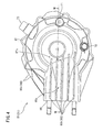
Fig. 4 is a left side view of the gear housing shown inFig. 3 . -
Fig. 5 is a perspective view of a rear side portion and a lower portion of the gear housing shown inFig. 3 . -
Fig. 6 is a left side view of the gear housing shown inFig. 3 . -
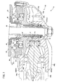
Fig. 7 is a sectional view taken along line VII-VII inFig. 4 . -
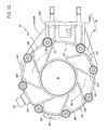
Fig. 8 is a right side view of an outside case shown inFig. 3 . -
Fig. 9 is a sectional view taken along line IX-IX inFig. 8 . -
Fig. 10 is a sectional view taken along line X-X inFig. 8 . -
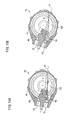
Fig. 11A is a sectional view of the gear housing when the motorcycle shown inFig. 1 is lifted upright without using a center stand and the front wheel and the rear wheel are in contact with the ground surface. -
Fig. 11B is a sectional view of the gear housing when the motorcycle shown inFig. 1 is lifted with using the center stand and the rear wheel is lifted off from the ground surface. -
Fig. 12 is a perspective view of a rear side portion and a lower portion of a gear housing according to another preferred embodiment of the present invention. -
Fig. 13 is a perspective view of a rear side portion and a lower portion of a gear housing according to yet another preferred embodiment of the present invention. -
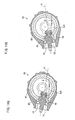
Fig. 14A is a sectional view of the gear housing in which a ball bearing and a needle bearing entirely emerge from lubricant oil when the front wheel and the rear wheel of the motorcycle shown inFig. 1 are in contact with the ground surface. -
Fig. 14B is a sectional view of the gear housing in which the ball bearing and the needle bearing are partly immersed in the lubricant oil when the gear housing swings to a position above the position of the gear housing when the front wheel and the rear wheel of the motorcycle shown inFig. 1 are in contact with the ground surface. - A preferred embodiment of the present invention will be described in detail in conjunction with the accompanying drawings in which the same or corresponding elements are designated by the same reference characters and their description will not be repeated.
- In
Fig. 1 , the x-direction refers to the front-back direction of the vehicle body, the y-direction refers to the widthwise direction of the vehicle body, and the z-direction refers to the up-down direction of the vehicle body. The front-back direction, the widthwise direction, and the up-down direction of the vehicle body are orthogonal to one another. When the vehicle body is upright, the vehicle front-back and widthwise directions are both horizontal and the up-down direction is the vertical direction. Herein, the "front," "back," "right," and "left" refer to these directions seen from a rider seated on themotorcycle 1. Therefore, the left inFig. 1 indicates the front of themotorcycle 1. - The
motorcycle 1 includes avehicle body frame 3. Thevehicle body frame 3 includes anengine 5, a fuel tank 7, and aseat 9. Theengine 5 is provided under thevehicle body frame 3. The fuel tank 7 is provided above thevehicle body frame 3 and closer to the front. Theseat 9 is provided above thevehicle body frame 3 and closer to the back. Acenter stand 13 is provided rotatably under thevehicle body frame 3. When the center stand 13 is upright, therear wheel 11 is lifted off from the ground surface. - A
head pipe 15 is fixed to the rear end of thevehicle body frame 3. Thehead pipe 15 supports a steering shaft (not shown) around the axial center rotatably. Afront fork 19 is coupled to the steering shaft through ahandle crown 17 and an underbracket 18. Afront wheel 21 is supported rotatably under thefront fork 19. Ahandle 22 is coupled to the steering shaft through thehandle crown 17. - A
swing arm 23 is supported at the rear end of thevehicle body frame 3 swingably around apivot shaft 25. Theswing arm 23 has aright swing arm 23R (seeFig. 2 ) that extends from thepivot shaft 25 to the right of therear wheel 11 and aleft swing arm 23L that extends from thepivot shaft 25 to the left of therear wheel 11. - The
swing arm 23 is coupled to thevehicle body frame 3 by arear suspension mechanism 27. Therear suspension mechanism 27 is a so-called bottom link suspension and includes ashock absorber 27a and links 27b and 27c. Therear suspension mechanism 27 absorbs impact from the road surface. - The
left swing arm 23L supports thegear housing 31. Thegear housing 31 is fixed to the rear end of theleft swing arm 23L and swings together with theleft swing arm 23L around thepivot shaft 25. - Referring to
Fig. 2 , thegear housing 31 and theright swing arm 23R support theaxle shaft 33 for therear shaft 11. One end of theaxle shaft 33 is coupled to thegear housing 31. The other end of theaxle shaft 33 is coupled to the rear end of theright swing arm 23R. Therefore, theaxle shaft 33 swings together with theswing arm 23. - The
axle shaft 33 supports the singlerear wheel 11 rotatably. Therear wheel 11 is provided only on the right side of thegear housing 31 and nothing is provided on the left side of thegear housing 31. Theaxle shaft 33 supports adisk brake unit 34 between therear wheel 11 and theright swing arm 23R. - Referring to
Figs. 1 and2 , theengine 5 includes acrankcase 35. Thecrankcase 35 includes a crankshaft, a transmission, and anoutput shaft 37. Theoutput shaft 37 is provided at the rear portion of thecrankcase 35 substantially parallel to the vehicle widthwise direction. Theoutput shaft 37 rotates around its axial center by power generated by theengine 5. - A
shaft drive mechanism 41 is coupled to theoutput shaft 37 through amiddle gear unit 39. Themiddle gear unit 39 is a bevel gear unit and includes a drivingbevel gear 39a and a drivenbevel gear 39b. The drivingbevel gear 39a is coupled coaxially with theoutput shaft 37. The drivenbevel gear 39b is coupled to the front end of theshaft drive mechanism 41. The rotation shaft A2 of the drivenbevel gear 39b is provided substantially at the same height as the rotation shaft A3 of the driving bevel gear 39a. Power is transmitted from theoutput shaft 37 to theshaft drive mechanism 41 through themiddle gear unit 39 having the above-described structure. - The
rear gear unit 43 is coupled to the rear end portion of theshaft drive mechanism 41. Therear gear unit 43 is stored in thegear housing 31. Therear gear unit 43 has a smalldiameter pinion gear 45 and a largediameter ring gear 47 that are engaged with each other. - As shown in
Fig. 1 , the rotation axis A1 of thepinion gear 45 is offset downward from the rotation center P of thering gear 47. Thepinion gear 45 is coupled to the rear end of theshaft drive mechanism 41. - Referring to
Fig. 2 , thering gear 47 is coupled to ahub clutch member 49 by spline coupling at the outer portion of thegear housing 31. Thehub clutch member 49 is held rotatably at theaxle shaft 33 by a ball bearing 50 and rotates together with thering gear 47. Arubber damper 51 is fixed to thehub clutch member 49. - The
rear wheel 11 includes acast wheel 53 and atire 55. However, the rear wheel may include a spoke wheel. Thecast wheel 53 is held rotatably at theaxle shaft 33 by twoball bearings 57 and 58. Therubber damper 51 is pressed against thehub 53a of thecast wheel 53 and therubber damper 51 is in surface-contact with thehub 53a. In this way, power is transmitted between therubber damper 51 and thehub 53a while impact is absorbed. In this way, thering gear 47 is coupled to therear wheel 11 through thehub clutch member 49 and therubber damper 51. Therefore, thering gear 47 rotates together with therear wheel 11. - When the
shaft drive mechanism 41 rotates, the rear gear unit 43 (thepinion gear 5 and the ring gear 47) lowers the rotation speed of theshaft drive mechanism 41 while changing the rotation direction of theshaft drive mechanism 41 by about 90° and rotates the rear wheel. In this way, themotorcycle 1 advances. - Referring to
Fig. 2 , the structure of theshaft drive mechanism 41 will be described. Theshaft drive mechanism 41 includes adrive shaft 41a, a universal joint 41b, and adriveshaft 41c. The universal joint 41b is coupled between thedrive shafts drive shaft 41a and the rotation axis of thedrive shaft 41c to be folded. The universal joint 41b has its rotation center arranged in a position on an extension of thepivot shaft 25. - The driven
bevel gear 39b of themiddle gear unit 39 is coupled coaxially with the front end of thedrive shaft 41a. Thedrive shaft 41a is supported at thecrankcase 35 rotatably by a bearing (not shown). - The
drive shaft 41c is supported at theleft swing arm 23L rotatably around the axial center of thedrive shaft 41c by a bearing (not shown). Theleft swing arm 23L has a substantially cylindrical shape. Thedrive shaft 41c is inserted in theleft swing arm 23L. In this way, thedrive shaft 41c can swing around thepivot shaft 25 together with theleft swing arm 23L. - The rear end of the
drive shaft 41c is coupled to thepinion gear 45 through agear coupling 59. Thegear coupling 59 includes aninner tube 59a having a spur gear (external gear) and anouter tube 59b having an internal gear to be engaged with the spur gear. Theinner tube 59a is coupled coaxially with the rear end of thedrive shaft 41c. Theouter tube 59b is fixed to one end of thepinion gear 45. Thegear coupling 59 absorbs shifts and the like between the rotation axis of thedrive shaft 41c and the rotation axis A1 of thepinion gear 45 and smoothly transmits power from thedrive shaft 41c to thepinion gear 45. - In this description, a "front side portion" refers to a side opposite to the side of the
rear wheel 11 between both sides in the vehicle widthwise direction y. A "rear side portion" refers to a side on the side of therear wheel 11 between both sides in the vehicle widthwise direction y. According to the present preferred embodiment, the terms "front side portion" and the "rear side portion" are used to specify not only one side of the "gear housing 31" but also one side of a "tubular portion 65," a "disk shapedportion 67" or the like (that will be described) as required. - Referring to
Figs. 3 to 6 , thegear housing 31 includes anoutside case 61 and aninside cover 63. Theoutside case 61 includes thetubular portion 65 that has a tubular shape (somewhat like a quadratic prism shape) and the disk shapedportion 67 having a disk shape (or bowl shape). Thetubular portion 65 extends along substantially in the front-back direction x and has its rear end connected continuously to the disk shapedportion 67. The center of the disk shapedportion 67 is substantially in coincidence with the vehicle widthwise direction y and an opening C is formed substantially in the center of the front side portion 67o of the disk shapedportion 67, and theaxle shaft 33 is held at the opening C. Theinside cover 63 is coupled to the rear side portion of the disk shapedportion 67. Theinside cover 63 is an annular, substantially flat plate shaped element having an opening B in the center. - As shown in
Fig. 4 , the front side portion of thegear housing 31 is formed by the front side portion 65o of thetubular portion 65 and the front side portion 67o of the disk shapedportion 67. The front side portion 67o of the disk shapedportion 67 includes aninjection portion 71 used to inject lubricant oil into thegear housing 31, adischarge portion 72 used to discharge lubricant oil in thegear housing 31, and abreather device 73 used to communicate the inside of thegear housing 31 with the atmosphere. As shown inFig. 6 , the rear side portion of thegear housing 31 includes theinside cover 63 and therear side portion 65i of thetubular portion 65. - Referring to
Fig. 7 , the internal structure of thegear housing 31 will be described. The rear end of theleft swing arm 23L is fixed to the front end of thetubular portion 65 and the axial center of thetubular portion 65 is arranged to substantially coincide with the rotation axis of thedrive shaft 41c. - The
pinion gear 45 is mainly provided in thetubular portion 65 so to have its rotation axis A1 arranged substantially parallel to the axial center of thetubular portion 65. Thepinion gear 45 is held by thetubular portion 65 rotatably by aball bearing 75 and aneedle bearing 76. Theball bearing 75 and theneedle bearing 76 are bearings for pinion gears. - The
ring gear 47 is provided between the disk shapedportion 67 and theinside cover 63. A substantiallycylindrical collar 77 is integrally fitted into the opening formed in the center of thering gear 47. Theinside cover 63 supports theball bearing 78 that holds thering gear 47 itself rotatablly. The disk shaped portion 67 (outside case 61) supports theneedle bearing 79 that holds thecollar 77 rotatably. Thering gear 47 is held rotatably at thegear housing 31 by theball bearing 78 and theneedle bearing 79. - The inside of the
tubular portion 65 or the inside of the part where the tubular 65 continues to the disk shapedportion 67 corresponds to a position where thepinion gear 45 and thering gear 47 are engaged with each other. Stated differently, at the part of thegear housing 31 on the side closer to the front in the front-back direction x, thepinion gear 45 and thering gear 47 are engaged with each other. - The
axle shaft 33 is inserted into thegear housing 31 through the opening B of theinside cover 63 and the opening of thering gear 47. A small gap is secured between theaxle shaft 33 and thering gear 47. - Referring back to
Figs. 3 and4 , anouter fin 83 is provided at the outer surface of thegear housing 31. The fin receives traveling wind and carries out heat exchange with the outside air while themotorcycle 1 travels. Theouter fin 83 hashorizontal fins 83h andvertical fins 83vFig. 3 also shows the direction W1 of traveling wind. - The
horizontal fin 83h projects substantially in the horizontal direction within the range from the front side portion 65o of thetubular portion 65 to the center of the front side portion 67o of the disk shapedportion 67. Each of thehorizontal fins 83h is a flat plate element substantially parallel to the axial center of thetubular portion 65. Therefore, each of thehorizontal fins 83h is substantially parallel to the rotation axis A1 of thepinion gear 45 and the front-back direction x. - As shown in
Fig. 4 , thehorizontal fins 83h are arranged at intervals among one another in the vertical direction z entirely across the front side portion 65o of thetubular portion 65. When thegear housing 31 is viewed laterally, the range in which thehorizontal fins 83h are arranged corresponds to the part where thepinion gear 45 and thering gear 47 are engaged with each other. Thehorizontal fins 83h are integrally formed with theoutside case 61. - The
vertical fins 83v project substantially in the vertical direction from the upper portion 65u of thetubular portion 65 to the center of theupper portion 67u of the disk shapedportion 67. The vertical fins 83V are a plurality of (three) flat plate elements substantially parallel to the axial center of thetubular portion 65. Therefore, thevertical fins 83v are also substantially parallel to the rotation axis A1 of thepinion gear 45 and the front-back direction x. - The
vertical fins 83v are arranged at intervals among one another in the vehicle widthwise direction y across the entire upper portion 65u of thetubular portion 65. When thegear housing 31 is viewed from the top, the range within which thevertical fins 83v are arranged corresponds to the part where thepinion gear 45 and therig gear 47 are engaged with each other. Thevertical fins 83v are also formed integrally with theoutside case 61. - Referring to
Figs. 5 and6 , the rear side portion of thegear housing 31 is further provided with theinner fins 85 used for heat exchange with the atmosphere through swirling flow generated by the rotation of therear wheel 11. The swirling flow is air flow that swirls around theaxle shaft 33.Fig. 6 shows the direction W2 of the swirling flow. - The
inner fins 85 project from theinside cover 63. Theinner fins 85 are arranged radially around theaxle shaft 33. More specifically, theinner fins 85 are flat plate type elements that extend radially from the center of theaxle shaft 33 and arranged at intervals in the circumferential direction. Theinner fins 85 are formed in the range from the opening B of theinside cover 63 to the circumferential edge of theinside cover 63. Theinner fins 85 are integrally formed with theinside cover 63. - An
entry preventing member 87 is provided in an upper region of theinside cover 63. Theentry preventing member 87 prevents foreign substances such as flying pebbles from entering between theinner fins 85. Theentry preventing member 87 is formed by a plurality ofclaw pieces 89. - The
claw pieces 89 are provided at intervals along the upper circumferential portion of theinside cover 63. The distance E between theclaw pieces 89 is set to a size such as 5 mm that is slightly smaller than the size of a foreign substance such as a pebble that may not slip through the gap between theinside cover 63 and the opposingrubber damper 51 and remain there. - As shown in
Figs. 5 and7 , the surface of theinside cover 63 also has an annular raisedportion 90 provided across theinner fins 85 and having a projection height smaller than theinner fins 85. In a space partitioned by the annular raisedportion 90 and a pair ofinner fins 85 and open upward, foreign substances larger than the gaps formed by these elements and theopposed rubber damper 51 and could enter and be caught between theinner fins 85. More specifically, as shown inFig. 7 , a foreign substance larger than the distance D between the annular raisedportion 90 and therubber damper 51 is caught between theinside cover 63 and therubber damper 51. Therefore, the distance E between theclaw pieces 89 is preferably slightly smaller than the distance D between the annular raisedportion 90 and therubber damper 51. - The
entry preventing member 87 having the above-described structure can prevent entry of foreign substances that could be caught between theinner fins 85 by theclaw pieces 89 while the outside air can be passed through between theclaw pieces 89. Foreign substances that can be passed through between theclaw pieces 89 are limited to the ones with a smaller size than the minimum interval (distance) D between theinner fins 85. In this way, foreign substances are unlikely to be caught between theinner fins 85. - Referring to
Figs. 8 to 10 , anoil sump 91 used to temporarily store lubricant oil is provided in thegear housing 31. Theoil sump 91 forms a temporary fountain F between itself and the inner wall of thegear housing 31. Now, theoil sump 91 and the temporary fountain F will be described. - As shown in
Figs. 9 and 10 , arib member 93 that protrudes from theinner back surface 67a of the disk shapedportion 67 to thering gear 47 is provided. Therib member 93 is divided into anannular rib member 93a and alinear rib member 93b. The length of the protrusion of theannular rib member 93a is greater than the protrusion length of thelinear rib member 93b. Theannular rib member 93a and thelinear rib member 93b are formed integrally with the disk shaped portion 67 (outside case 61). - As shown in
Fig. 8 , theannular rib member 93a has a substantially cylindrical shape removed of a part where thepinion gear 45 is provided. Thelinear rib member 93b has a flat plate shape that extends in the radial direction substantially around theaxle shaft 33. Theannular rib member 93a and thelinear rib member 93b intersect each other in various positions. - The
oil sump 91 is a flat plate element having a substantially sectorial shape and includes an upper side portion at the tip end of theannular rib member 93a and aside wall plate 95 abutted against two adjacentlinear rib members 93b. Theside wall plate 95 is fixed to therib member 93 in a position where theannular rib member 93a and thelinear rib member 93b interest. With respect to the rotation direction G of thering gear 47, therear end 95b of theside wall plate 95 is set in a position where thelinear rib member 93b is not provided. With respect to the rotation direction G of thering gear 47 thefront end 95f of theside wall plate 95 is set in a position where thelinear rib 93 is not provided. - In this way, the temporary fountain F having the
annular rib member 93a as the bottom surface and surrounded by theinner back surface 67a of the disk shapedportion 67, theside wall plate 95 and the twolinear rib members 93b is formed. The temporary fountain F is opposed to the upper side portion of the tooth surface of thering gear 47. More specifically, the temporary fountain F is on the lateral side of thetooth surface 47a and close to thetooth surface 47 of thering gear 47. - As shown in
Fig. 8 , the upper part of theside wall plate 95 surrounded by the twolinear rib members 93b serves as an inlet Fi through which lubricant oil comes into the temporary fountain F. As shown inFig. 9 , the inlet Fi is cut at the upper part of thelinear rib 93b on the upstream side with respect to the rotation direction G of thering gear 47 among the twolinear rib members 93b. The inlets Fi are positioned in the flow path of the lubricant oil taken around with thering gear 47 and the lubricant oil is automatically allowed to flow into the inlets as thering gear 47 rotates. On the other hand, as shown inFig. 10 , among the twolinear rib members 93b, thelinear rib 93b on the front side with respect to the rotation direction G of thering gear 47 has no notch. - As shown in
Fig. 8 , small diameter outlets Fo that discharge lubricant oil from the temporary fountain F are formed under theside wall plate 95. The flow path area of the outlets Fo is smaller than the flow path area of the outlets Fi. - Since the temporary fountain F is always communicated with the inside of the
gear housing 31 through the outlets Fo, the lubricant oil cannot be kept stored. However, the lubricant oil taken around with thering gear 47 smoothly comes into the temporary fountain F and the lubricant oil is gradually discharged, so that the lubricant oil can be retained temporarily. As a result, the level of the lubricant oil in thegear housing 31 can be lowered temporarily. - Since the
gear housing 31 swings around thepivot shaft 25, the relative position between thebearings gear housing 31 changes in the gear hosing 31. According to the preferred embodiment, the positional relation is previously specified for each position of the gear hosing 31 in consideration of the relation between theball bearing 75 and theneedle bearing 76 that hold thepinion gear 45 and the oil level of the lubricant oil in thegear housing 31. The amount of the lubricant oil is set so that the previously specified relation is established for each position. Now, the specified positional relation will be described more specifically asconditions 1 and 2. - As shown in
Fig. 11A , in thecondition 1, "when thefront wheel 21 and therear wheel 11 are in contact with the ground surface, theball bearing 75 and theneedle bearing 76 are partly immersed in lubricant oil LO." Stated differently, the level S of the lubricant oil LO must be positioned above the lower end of each of theball bearing 75 and theneedle bearing 76 as themotorcycle 1 is upright without using thecenter stand 13. Thiscondition 1 specifies the minimum amount of the lubricant oil LO in thegear housing 31. - As shown in
Fig. 11B , in the condition 2, "when therear wheel 11 is apart from the ground surface, theball bearing 75 and theneedle bearing 76 entirely emerge from the lubricant oil LO." Stated differently, when therear wheel 11 is lifted off from the ground on thecenter stand 13, no part of both theball bearing 75 and theneedle bearing 76 is immersed in the lubricant oil LO. When therear wheel 11 is lifted off on thecenter stand 13, thegear housing 31 rotates downward around thepivot shaft 25, and therefore theball bearing 75 and theneedle bearing 76 are in a relatively higher position than the level S. In the condition 2, the maximum amount of the lubricant oil LO in thegear housing 31 is specified. - The amount of the lubricant oil LO in the
gear housing 31 is set to satisfy theconditions 1 and 2 described above. - Now, the operation of the
motorcycle 1 according to the present preferred embodiment will be described. - When the
motorcycle 1 has therear wheel 11 lifted off from the ground using thecenter stand 13, the lubricant oil LO is not supplied to theball bearing 75 and theneedle bearing 76 as shown inFig. 11B . The lubricant oil LO is not retained in the temporary fountain F. - When the
motorcycle 1 is started to travel, the center stand 13 is stored. Then, thefront wheel 21 and therear wheel 11 come into contact with the flat ground, and then the lubricant oil LO is supplied to at least a part of theball bearing 75 and theneedle bearing 76. In this way, in order to get themotorcycle 1 ready for traveling, the lubricant oil LO is always supplied to theball bearing 75 and theneedle bearing 76 before the vehicle is started. - When the
motorcycle 1 travels, theswing arm 23 swings around thepivot shaft 25, so that thegear housing 31 swings in the vertical direction while changing its position. The change in the position of thegear housing 31 allows the lubricant oil LO in thegear housing 31 to flow and the level S of the lubricant oil LO is inclined. As a result, the lubricant oil LO is supplied to a wider range in thegear housing 31. - The
ring gear 47 rotates in thegear housing 31. The lubricant oil LO is taken around with thering gear 47. The lubricant oil LO thus taken around is drawn upward from the level S in the rotation direction G of thering gear 47 mainly along thetooth surface 47a of thering gear 47. The drawn up lubricant oil LO comes into the temporary fountain F from the inlets Fi at the various locations. The lubricant oil LO that has come into the fountain is discharged from the temporary fountain F through the outlets Fo. The inflow into the temporary fountain F exceeds the amount that can be discharged from the outlets Fo and therefore the lubricant oil LO temporarily remains in the temporary fountain F. As a result, the level S of the lubricant oil LO in thegear housing 31 is lower than the original level S corresponding to the oil amount of the lubricant oil LO in thegear housing 31. - When the level S of the lubricant oil LO is lowered, the capacity of the
ring gear 47 in contact with the lubricant oil LO under the level S is reduced, and the resistance of the lubricant oil LO against the rotation of thering gear 47 is reduced. Therefore, power transmission loss at therear gear unit 43 is reduced. - The largest amount of heat is generated from the part where the
pinion gear 45 and thering gear 47 are engaged with each other in thegear housing 31. In addition, the lubricant oil LO is scattered by the rotation of thering gear 47 and collides against various parts in thegear housing 31, so that the temperature of the lubricant oil LO is raised. - At the outer surface of the
gear housing 31, traveling wind flows around thehorizontal fins 83h and thevertical fins 83v in the direction from the front to the back of themotorcycle 1. Since thehorizontal fins 83h and thevertical fins 83v are both substantially parallel to the front-back direction, and therefore the traveling wind flows along the surfaces of thehorizontal fins 83h and thevertical fins 83v. Therefore, the heat of thehorizontal fins 83h and thevertical fins 83v can be radiated efficiently to the outside air, so that thegear housing 31 and the lubricant oil Lo in thegear housing 31 can be cooled in an optimum manner. - The
rear wheel 11 rotates around theaxle shaft 33, so that swirling flow is generated around theaxle shaft 33 in the in the periphery of theinner fins 85. Therear side fins 85 are parallel to the radial direction around theaxle shaft 33 and therefore the swirling flow blows perpendicularly at theinner fins 85. In this way, heat exchange is efficiently carried out between theinner fins 85 and the outside air. - When the
motorcycle 1 stops traveling and theengine 5 is stopped, thering gear 47 stops rotating. In this way, the lubricant oil Lo stops to be brought up and no longer comes into the temporary fountain F. Therefore, the lubricant oil LO entirely flows downward through the outlets Fo with time. As a result, the level S of the lubricant oil LO in thegear housing 31 is returned to the height of the original level S corresponding to the amount of the lubricant oil LO. - The
motorcycle 1 according to the present preferred embodiment includes therear gear unit 43 in which the rotation axis A1 of thepinion gear 45 is offset downward from the rotation center P of thering gear 47 and theswing arm 23 having thegear housing 31 that stores therear gear unit 43 swing around thepivot shaft 25. Therefore, thegear housing 31 has its position changed and can naturally supply the lubricant oil LO in a wider range in thegear housing 31. As a result, as compared to when thehousing gear 31 is translated in the vertical direction without the swinging of thegear housing 31, the amount of the lubricant oil LO in thegear housing 31 can surely be reduced. - According to the present preferred embodiment, the amount of the lubricant oil LO in the
gear housing 31 is set so that the condition based on the positional relation between theball bearing 75 and theneedle bearing 76 and the level S of the lubricant oil LO in thegear housing 31 is satisfied. Therefore, the amount of the lubricant oil LO in thegear housing 31 can surely be reduced. - According to the present preferred embodiment, the
oil sump 91 is provided and the temporary fountain F is formed in an upper position of thegear housing 31, so that the lubricant oil LO can be retained temporarily. In this way, when thering gear 47 rotates, the level S of the lubricant oil LO can be further lowered when thering gear 47 rotates. - The lubricant oil LO taken around with the
ring gear 47 comes into the temporary fountain F by itself, so that no power is necessary to guide the lubricant oil LO into the temporary fountain F. As a result, the resistance thering gear 47 receives from the lubricant oil LO during the rotation of thering gear 47 is reduced, and therear gear unit 43 can transmit power efficiently from theengine 5 to therear wheel 11. In addition, thering gear 47 reduces the amount of the lubricant oil LO to be scattered, so that the amount of heat generated by the collision of the lubricant oil LO can be reduced. - The fins (i.e., the
outer fin 83 and the inner fins 85) are provided at the outer side of thegear housing 31, and therefore thegear housing 31 and the lubricant oil LO in thegear housing 31 can be cooled efficiently. In this way, when the amount of the lubricant oil LO in thegear housing 31 is reduced, the lubricant oil LO can be prevented from being degraded. - The outer fin 83 (the
horizontal fins 83h and thevertical fins 83v) is provided in a position corresponding the part where thepinion gear 45 and thering gear 47 are engaged with each other (i.e., where the outer surface of thegear housing 31 is at the highest temperature). Therefore, theouter fin 83 can cool thegear housing 31 effectively. - Since the
horizontal fins 83h and thevertical fins 83v have shapes parallel to traveling wind, and therefore fresh outside air is always supplied around thehorizontal fins 83h and thevertical fins 83v. Therefore, heat exchange can be carried out efficiently between thehorizontal fins 83h and thevertical fins 83v and the outside air. - The
inner fins 85 are provided radially to theaxle shaft 33 coaxial with the center of the swirling flow of therear wheel 11, and therefore the swirling flow blows against theinner fins 85 efficiently. Therefore, heat exchange can be carried out efficiently between theinner fins 85 and the outside air. - The present invention is not limited to the above-described preferred embodiment and can be modified as in the following.
- (1) In the above-described preferred embodiment, the
outer fin 83 is provided at the front side portion 65o and the upper portion 65u of thetubular portion 65 and the front side portion 67o and theupper portion 67u of the disk shapedportion 67, but the invention is not limited to this arrangement. More specifically, theouter fins 83 may be provided at any of the upper portion, the lower portion, and the front side portion of thegear housing 31. For example, theouter fin 83 may be provided at thelower portion 651 of thetubular portion 65 or thelower portion 671 of the disk shapedportion 67 shown inFig. 5 . Theouter fin 83 may be provided only at thetubular portion 65 instead of providing them from thetubular portion 65 to the disk shapedportion 67.
When thegear housing 31 does not have thetubular portion 65 or the disk shapedportion 67, theouter fins 83 may be provided at least at one of the upper portion, the lower portion, and the front side portion of thegear housing 31. - (2) In the above-described preferred embodiment, the
horizontal fins 83h and thevertical fins 83v are both flat plate shaped, but the shape is not limited to this shape. More specifically, theouter fin 83 can be modified as required to have shapes that can receive traveling wind efficiently. For example, a curved shape may be employed. - (3) In the above-described preferred embodiment, the
horizontal fins 83h and thevertical fins 83v are substantially parallel to the front-back direction x, but the invention is not limited to this arrangement. For example, when the rotation axis A1 of thepinion gear 45 or the axial center of thetubular portion 65 is not substantially parallel to the front-back direction x, thehorizontal fins 83h and thevertical fins 83v may be changed so that these fins are substantially parallel to the rotation axis A1 of thepinion gear 45 or the axial center of thetubular portion 65. Alternatively, fins that are substantially nonparallel to any of the front-back direction x, the rotation axis A1 and the axial center of thetubular portion 65 may be employed as with the case when fins with curved surfaces are used as described above. - (4) In the above-described preferred embodiment, the
horizontal fins 83h are arranged substantially parallel to one another, but the invention is not limited to this arrangement. For example, thehorizontal fins 83h may be arranged radially. This also applies to thevertical fins 83v - (5) In the above-described preferred embodiment, the
inner fins 85 are flat plate type elements that extend radially around theaxle shaft 33, but the invention is not limited to this arrangement. Now, modifications of the inner fins will be described with reference to the drawings.
Referring toFig. 12 , ainner fin 101 includes a plurality of raisedportions 102 arranged apart from one another in the radial direction around theaxle shaft 33. Theinner fin 101 includes a plurality of raisedportions 103 arranged apart from one another in the circumferential direction around theaxle shaft 33. Theinner fin 101 in this arrangement has an increased surface area in contact with swirling flow, so that heat exchange with the outside air can be carried out even more efficiently.
Referring toFig. 13 ,inner fins 105 are arranged radially around theaxial shaft 33. However, theinner fins 105 are different from theinner fins 85 in that they not formed along the radius of theinner cover 63. Theinner fins 105 in this arrangement guide swirling flow to the lateral side of theinner cover 63, so that heat exchange with the outside air can be carried out efficiently. - (6) In the above-described preferred embodiment, the
entry preventing member 87 includes the plurality ofclaw pieces 89 arranged apart from one another, but the invention is not limited to this arrangement. For example, as shown inFig. 13 , theentry preventing member 87 may be formed bywall portions 107 that projects continuously along the circumference of theinner cover 63. - (7) In the above-described preferred embodiment, the
entry preventing member 87 is formed only in a region on the upper side of theinner cover 63, the invention is not limited to this arrangement. For example, as shown inFig. 13 , the entry preventing member 87 (wall portions 107) may be provided along the entire circumference of theinner cover 63. - (8) In the above-described preferred embodiment, the
oil sump 91 forms the temporary fountain F between itself and the inner wall of thegear housing 31, but the invention is not limited to this arrangement. For example, another member forming the bottom or side wall of the temporary fountain F may be provided in addition to theside wall plate 95 and the temporary fountain F may be formed without using the inner wall of thegear housing 31. - (9) In the above-described preferred embodiment, the
side wall plate 95 that forms the temporary fountain F has a flat plate shape, but the invention is not limited to this arrangement. For example, the shape may be modified so that therear end 95b of theside wall plate 95 is curved to be close to thetooth surface 47a of thering gear 47. In this way, the inlet Fi can guide the lubricant oil LO actively into the temporary fountain F, and the lubricant oil LO can come into the temporary fountain F even more smoothly. - (10) In the above-described preferred embodiment, the outlet Fo of the temporary fountain F is an opening surrounded by the
front end 95f of theside wall plate 95, and thelinear rib member 93, but the invention is not limited to this arrangement. For example, an opening may be formed at least at one of theside wall plate 95, theannular rib member 93a and thelinear rib member 93b as the outlet Fo of the temporary fountain F. - (11) In the above-described preferred embodiment, the amount of the lubricant oil LO in the
gear housing 31 is set based on theconditions 1 and 2, but the invention is not limited to theseconditions 1 and 2.
As shown inFig. 14A , incondition 3, "when thefront wheel 21 and therear wheel 11 are in contact with the ground surface, theball bearing 75 and theneedle bearing 76 entirely emerge from the lubricant oil LO." As shown inFig. 14B , in condition 4, "when thegear housing 31 swings to a higher position than the position of thegear housing 31 while thefront wheel 21 and therear wheel 11 are in contact with the ground surface, theball bearing 75 and theneedle bearing 76 are partly immersed in the lubricant oil LO." The amount of the lubricant oil LO in thegear housing 31 may be set in order to satisfy theseconditions 3 and 4.
While themotorcycle 1 travels, thegear housing 31 swings and therefore the lubricant oil LO can be supplied to theball bearing 75 and theneedle bearing 76. When the state of themotorcycle 1 during traveling is considered, theball bearing 75 and theneedle bearing 76 can be supplied with the lubricant oil LO as required if the condition 4 is satisfied. Therefore, the amount of the lubricant oil LO can be more reduced by setting the amount of the lubricant oil LO to satisfy thecondition 3 within the range that satisfies the condition 4. - (12) In the above-described preferred embodiment, the conditions for setting the amount of the lubricant oil LO are specified in consideration of the
bearing 75 and theneedle bearing 76 that hold thepinion gear 45, but the invention is not limited to this arrangement. For example, a condition may be specified in consideration of thepinion gear 45 or thering gear 47 or of thebearing 78 and theneedle bearing 79 that hold thering gear 47. - (13) In the above-described preferred embodiment, the universal joint 41b is provided, but the invention is not limited to this arrangement. For example, the universal joint 41b may be replaced by a double Cardan joint or a constant velocity ball joint. The joint having velocity constancy can reduce fluctuations in the rotation of the
rear wheel 11. - (14) In the above-described preferred embodiment, the rotation axis A1 of the
pinion gear 45 is offset downward from the rotation center P of thering gear 47. However, the structure of theoil sump 91 in thegear housing 31 can be applied not only to therear gear unit 43 but also to various gear portions. For example, the structure of theoil sump 91 may be applied to a gear portion in which the rotation axis A1 of thepinion gear 45 intersects the rotation center P of thering gear 47. The structure of theoil sump 91 may be applied to a straight bevel gear or a spiral gear. - (15) In the above-described embodiment, the
swing arm 23L stores thedrive shaft 41c but the swing arm does not have to store thedrive shaft 41c. The swing arm can have any shape as required as long as it does not interfere with thedrive shaft 41c. In this case, thedrive shaft 41c may be exposed to the outside. - (16) The preferred embodiments described above and the modifications described above in (1) to (15) may be replaced by or combined with other modifications in various different forms as required.
- While preferred embodiments of the present invention have been described above, it is to be understood that variations and modifications will be apparent to those skilled in the art without departing the scope and spirit of the present invention. The scope of the present invention, therefore, is to be determined solely by the following claims.
Claims (15)
- A motorcycle (1), comprising:a vehicle body frame (3) having a pivot shaft (25);an engine (5) supported at the vehicle body frame;a swing arm (23) provided swingably around the pivot shaft (25);a rear wheel (11) provided rotatably at the swing arm;a first drive shaft (41c) provided to swing together with the swing arm to transmit driving force to the rear wheel;a gear housing (31) provided integrally with the swing arm to swing around the pivot shaft together with the swing arm;a pinion gear (45) stored in the gear housing and coupled coaxially with the rear end of the first drive shaft; anda ring gear (47) stored in the gear housing and coupled coaxially with an axle shaft (33) of the rear wheel, the ring gear being engaged with the pinion gear,a rotation axis (A1) of the pinion gear being offset downward from a rotation center (P) of the ring gear.
- The motorcycle according to claim 1, further comprising a bearing (75, 76) provided at the gear housing to hold the pinion gear rotatably, wherein lubricant oil (LO) in the gear housing is filled so that the entire bearing emerges from the lubricant oil when the motorcycle is lifted by a center stand (13) so that the rear wheel is lifted off from the ground surface.
- The motorcycle according to claim 1 or 2, wherein the first drive shaft extends straight in the front-back direction of the motorcycle.
- The motorcycle according to any one of claims 1 to 3, further comprising:a second drive shaft (41a);a universal joint (41b) provided on the pivot shaft and coupled between the first drive shaft and the second drive shaft;a driving bevel gear (39a) coupled coaxially with an output shaft (37) of the engine; anda driven bevel gear (39b) coupled coaxially with the front end of the second drive shaft and engaged with the driving bevel gear,a rotation axis (A2) of the driven bevel gear being provided at the same height as a rotation axis (A3) of the driving bevel gear.
- The motorcycle according to any one of claims 1 to 4, further comprising a fin (83, 85) provided at an outer surface of the gear housing.
- The motorcycle according to claim 4, wherein the fin is provided in a position corresponding to a part where the pinion gear and the ring gear are engaged with each other.
- The motorcycle according to claim 5 or 6, wherein the fin comprises an outer fin (83) provided at any one of an upper portion of the gear housing, a lower portion of the gear housing, and a front side portion of the gear housing.
- The motorcycle according to claim 7, wherein the outer fin is provided along the front-back direction of the motorcycle.
- The motorcycle according to claim 7 or 8, wherein the gear housing comprises:a tubular portion (65) extending along the front-back direction of the motorcycle and storing the pinion gear; anda disk shaped portion (67) connected to a rear end of the tubular portion and storing the ring gear, andthe outer fin comprises a horizontal fin (83h) projecting horizontally from a front side portion of the tubular portion.
- The motorcycle according to claim 9, wherein the outer fin further comprises a vertical fin (83v) extending vertically from an upper portion of the tubular portion.
- The motorcycle according to claims 5 to 10, wherein the fin comprises an inner fin (85) provided at a rear side portion of the gear housing.
- The motorcycle according to claim 11, wherein the inner fin is formed radially around the axle shaft of the rear wheel.
- The motorcycle according to claim 11 or 12, further comprising an entry preventing member (87) provided on an upper side of the rear side portion to prevent a foreign substance from entering between the inner fins, and wherein the entry preventing member comprises a plurality of claw pieces (89) provided apart from one another along a circumference of the upper side.
- The motorcycle according to any one of claims 1 to 13, wherein the gear housing comprises a temporary fountain (F) temporarily retaining lubricant oil taken around with the ring gear by a rotation of the ring gear.
- The motorcycle according to claim 14, wherein the temporary fountain is positioned above the axle shaft of the rear wheel, and wherein the temporary fountain comprises an inlet (Fi) provided on an upstream side with respect to a rotation direction of the ring gear.
Applications Claiming Priority (1)
| Application Number | Priority Date | Filing Date | Title |
|---|---|---|---|
| JP2009200318A JP2011051407A (en) | 2009-08-31 | 2009-08-31 | Motorcycle |
Publications (2)
| Publication Number | Publication Date |
|---|---|
| EP2289791A1 true EP2289791A1 (en) | 2011-03-02 |
| EP2289791B1 EP2289791B1 (en) | 2014-03-05 |
Family
ID=43063428
Family Applications (1)
| Application Number | Title | Priority Date | Filing Date |
|---|---|---|---|
| EP20100174691 Active EP2289791B1 (en) | 2009-08-31 | 2010-08-31 | Motorcycle |
Country Status (2)
| Country | Link |
|---|---|
| EP (1) | EP2289791B1 (en) |
| JP (1) | JP2011051407A (en) |
Families Citing this family (3)
| Publication number | Priority date | Publication date | Assignee | Title |
|---|---|---|---|---|
| WO2015097711A1 (en) * | 2013-12-27 | 2015-07-02 | DONGA, Rajendrabhai Vallabhbhai | Motorcycle transmission and suspension system |
| JP6536351B2 (en) * | 2015-10-27 | 2019-07-03 | スズキ株式会社 | Swing arm of electric motorcycle |
| JP7234004B2 (en) * | 2019-03-29 | 2023-03-07 | 本田技研工業株式会社 | gear device |
Citations (5)
| Publication number | Priority date | Publication date | Assignee | Title |
|---|---|---|---|---|
| GB393947A (en) * | 1931-12-10 | 1933-06-12 | John Shaw | Improvements relating to motor cycles and motor vehicles |
| US4436173A (en) * | 1981-05-15 | 1984-03-13 | Honda Giken Kogyo Kabushiki Kaisha | Shaft drive apparatus for motorized two-wheeled vehicle |
| JPH0972927A (en) | 1995-09-05 | 1997-03-18 | Yamaha Motor Co Ltd | Rear wheel rotation speed detection device for motorcycles |
| EP1361149A1 (en) * | 2001-10-19 | 2003-11-12 | Marco Doveri | Rear suspension for motorcycles with longitudinal shaft transmission |
| JP2008087585A (en) | 2006-09-29 | 2008-04-17 | Honda Motor Co Ltd | Motorcycle rear wheel drive system |
-
2009
- 2009-08-31 JP JP2009200318A patent/JP2011051407A/en active Pending
-
2010
- 2010-08-31 EP EP20100174691 patent/EP2289791B1/en active Active
Patent Citations (5)
| Publication number | Priority date | Publication date | Assignee | Title |
|---|---|---|---|---|
| GB393947A (en) * | 1931-12-10 | 1933-06-12 | John Shaw | Improvements relating to motor cycles and motor vehicles |
| US4436173A (en) * | 1981-05-15 | 1984-03-13 | Honda Giken Kogyo Kabushiki Kaisha | Shaft drive apparatus for motorized two-wheeled vehicle |
| JPH0972927A (en) | 1995-09-05 | 1997-03-18 | Yamaha Motor Co Ltd | Rear wheel rotation speed detection device for motorcycles |
| EP1361149A1 (en) * | 2001-10-19 | 2003-11-12 | Marco Doveri | Rear suspension for motorcycles with longitudinal shaft transmission |
| JP2008087585A (en) | 2006-09-29 | 2008-04-17 | Honda Motor Co Ltd | Motorcycle rear wheel drive system |
Also Published As
| Publication number | Publication date |
|---|---|
| JP2011051407A (en) | 2011-03-17 |
| EP2289791B1 (en) | 2014-03-05 |
Similar Documents
| Publication | Publication Date | Title |
|---|---|---|
| US8899381B2 (en) | Electric transaxle | |
| KR101444571B1 (en) | Hybrid saddled vehicle | |
| WO2012153589A1 (en) | Drive device for vehicle | |
| US9822867B2 (en) | Gear case for motorcycle | |
| CN211930404U (en) | Drive device | |
| US6805217B2 (en) | Power transmission mechanism of four-wheel drive vehicle | |
| JP6714463B2 (en) | In-wheel motor drive device and in-wheel motor drive device and wheel connection structure | |
| US6868932B1 (en) | Modular vehicle drivetrain | |
| EP2289791B1 (en) | Motorcycle | |
| JP5529091B2 (en) | Dump truck travel drive device | |
| ES2507560T3 (en) | Dry clutch and two wheel motor vehicle with dry clutch | |
| JP2021164297A (en) | Drive device | |
| JP2004026148A (en) | Pull-off bracket | |
| JP2019140906A (en) | Lubrication oil supply structure and in-wheel motor drive device | |
| CN101249871B (en) | Striding type vehicle | |
| CN117628153A (en) | Axle assembly with lubricant guide | |
| US7114598B2 (en) | Brake cooling mechanism of four-wheeled vehicle | |
| US20160281840A1 (en) | Shaft drive type vehicle | |
| JP2019156392A (en) | In-wheel motor drive device | |
| JP5438352B2 (en) | Steering damper device for saddle-ride type vehicles | |
| JP2006064056A (en) | Bearing lubrication structure for differential equipment | |
| JP6691520B2 (en) | Dump truck traveling equipment | |
| JP3722095B2 (en) | Four-wheel drive vehicle drive system | |
| JP7752717B1 (en) | Electric continuously variable transmission | |
| JP4531678B2 (en) | Shaft drive type vehicle |
Legal Events
| Date | Code | Title | Description |
|---|---|---|---|
| PUAI | Public reference made under article 153(3) epc to a published international application that has entered the european phase |
Free format text: ORIGINAL CODE: 0009012 |
|
| AK | Designated contracting states |
Kind code of ref document: A1 Designated state(s): AL AT BE BG CH CY CZ DE DK EE ES FI FR GB GR HR HU IE IS IT LI LT LU LV MC MK MT NL NO PL PT RO SE SI SK SM TR |
|
| AX | Request for extension of the european patent |
Extension state: BA ME RS |
|
| 17P | Request for examination filed |
Effective date: 20110902 |
|
| 17Q | First examination report despatched |
Effective date: 20120502 |
|
| GRAP | Despatch of communication of intention to grant a patent |
Free format text: ORIGINAL CODE: EPIDOSNIGR1 |
|
| INTG | Intention to grant announced |
Effective date: 20131002 |
|
| GRAS | Grant fee paid |
Free format text: ORIGINAL CODE: EPIDOSNIGR3 |
|
| GRAA | (expected) grant |
Free format text: ORIGINAL CODE: 0009210 |
|
| AK | Designated contracting states |
Kind code of ref document: B1 Designated state(s): AL AT BE BG CH CY CZ DE DK EE ES FI FR GB GR HR HU IE IS IT LI LT LU LV MC MK MT NL NO PL PT RO SE SI SK SM TR |
|
| REG | Reference to a national code |
Ref country code: GB Ref legal event code: FG4D |
|
| REG | Reference to a national code |
Ref country code: CH Ref legal event code: EP |
|
| REG | Reference to a national code |
Ref country code: AT Ref legal event code: REF Ref document number: 654671 Country of ref document: AT Kind code of ref document: T Effective date: 20140315 |
|
| REG | Reference to a national code |
Ref country code: IE Ref legal event code: FG4D |
|
| REG | Reference to a national code |
Ref country code: DE Ref legal event code: R096 Ref document number: 602010013917 Country of ref document: DE Effective date: 20140417 |
|
| REG | Reference to a national code |
Ref country code: AT Ref legal event code: MK05 Ref document number: 654671 Country of ref document: AT Kind code of ref document: T Effective date: 20140305 |
|
| REG | Reference to a national code |
Ref country code: NL Ref legal event code: VDEP Effective date: 20140305 |
|
| PG25 | Lapsed in a contracting state [announced via postgrant information from national office to epo] |
Ref country code: NO Free format text: LAPSE BECAUSE OF FAILURE TO SUBMIT A TRANSLATION OF THE DESCRIPTION OR TO PAY THE FEE WITHIN THE PRESCRIBED TIME-LIMIT Effective date: 20140605 Ref country code: LT Free format text: LAPSE BECAUSE OF FAILURE TO SUBMIT A TRANSLATION OF THE DESCRIPTION OR TO PAY THE FEE WITHIN THE PRESCRIBED TIME-LIMIT Effective date: 20140305 |
|
| REG | Reference to a national code |
Ref country code: LT Ref legal event code: MG4D |
|
| PG25 | Lapsed in a contracting state [announced via postgrant information from national office to epo] |
Ref country code: FI Free format text: LAPSE BECAUSE OF FAILURE TO SUBMIT A TRANSLATION OF THE DESCRIPTION OR TO PAY THE FEE WITHIN THE PRESCRIBED TIME-LIMIT Effective date: 20140305 Ref country code: AT Free format text: LAPSE BECAUSE OF FAILURE TO SUBMIT A TRANSLATION OF THE DESCRIPTION OR TO PAY THE FEE WITHIN THE PRESCRIBED TIME-LIMIT Effective date: 20140305 Ref country code: CY Free format text: LAPSE BECAUSE OF FAILURE TO SUBMIT A TRANSLATION OF THE DESCRIPTION OR TO PAY THE FEE WITHIN THE PRESCRIBED TIME-LIMIT Effective date: 20140305 Ref country code: SE Free format text: LAPSE BECAUSE OF FAILURE TO SUBMIT A TRANSLATION OF THE DESCRIPTION OR TO PAY THE FEE WITHIN THE PRESCRIBED TIME-LIMIT Effective date: 20140305 |
|
| PG25 | Lapsed in a contracting state [announced via postgrant information from national office to epo] |
Ref country code: HR Free format text: LAPSE BECAUSE OF FAILURE TO SUBMIT A TRANSLATION OF THE DESCRIPTION OR TO PAY THE FEE WITHIN THE PRESCRIBED TIME-LIMIT Effective date: 20140305 Ref country code: LV Free format text: LAPSE BECAUSE OF FAILURE TO SUBMIT A TRANSLATION OF THE DESCRIPTION OR TO PAY THE FEE WITHIN THE PRESCRIBED TIME-LIMIT Effective date: 20140305 |
|
| PG25 | Lapsed in a contracting state [announced via postgrant information from national office to epo] |
Ref country code: BG Free format text: LAPSE BECAUSE OF FAILURE TO SUBMIT A TRANSLATION OF THE DESCRIPTION OR TO PAY THE FEE WITHIN THE PRESCRIBED TIME-LIMIT Effective date: 20140605 Ref country code: CZ Free format text: LAPSE BECAUSE OF FAILURE TO SUBMIT A TRANSLATION OF THE DESCRIPTION OR TO PAY THE FEE WITHIN THE PRESCRIBED TIME-LIMIT Effective date: 20140305 Ref country code: IS Free format text: LAPSE BECAUSE OF FAILURE TO SUBMIT A TRANSLATION OF THE DESCRIPTION OR TO PAY THE FEE WITHIN THE PRESCRIBED TIME-LIMIT Effective date: 20140705 Ref country code: RO Free format text: LAPSE BECAUSE OF FAILURE TO SUBMIT A TRANSLATION OF THE DESCRIPTION OR TO PAY THE FEE WITHIN THE PRESCRIBED TIME-LIMIT Effective date: 20140305 Ref country code: NL Free format text: LAPSE BECAUSE OF FAILURE TO SUBMIT A TRANSLATION OF THE DESCRIPTION OR TO PAY THE FEE WITHIN THE PRESCRIBED TIME-LIMIT Effective date: 20140305 Ref country code: BE Free format text: LAPSE BECAUSE OF FAILURE TO SUBMIT A TRANSLATION OF THE DESCRIPTION OR TO PAY THE FEE WITHIN THE PRESCRIBED TIME-LIMIT Effective date: 20140305 Ref country code: EE Free format text: LAPSE BECAUSE OF FAILURE TO SUBMIT A TRANSLATION OF THE DESCRIPTION OR TO PAY THE FEE WITHIN THE PRESCRIBED TIME-LIMIT Effective date: 20140305 |
|
| PG25 | Lapsed in a contracting state [announced via postgrant information from national office to epo] |
Ref country code: PL Free format text: LAPSE BECAUSE OF FAILURE TO SUBMIT A TRANSLATION OF THE DESCRIPTION OR TO PAY THE FEE WITHIN THE PRESCRIBED TIME-LIMIT Effective date: 20140305 Ref country code: SK Free format text: LAPSE BECAUSE OF FAILURE TO SUBMIT A TRANSLATION OF THE DESCRIPTION OR TO PAY THE FEE WITHIN THE PRESCRIBED TIME-LIMIT Effective date: 20140305 Ref country code: ES Free format text: LAPSE BECAUSE OF FAILURE TO SUBMIT A TRANSLATION OF THE DESCRIPTION OR TO PAY THE FEE WITHIN THE PRESCRIBED TIME-LIMIT Effective date: 20140305 |
|
| REG | Reference to a national code |
Ref country code: DE Ref legal event code: R097 Ref document number: 602010013917 Country of ref document: DE |
|
| PG25 | Lapsed in a contracting state [announced via postgrant information from national office to epo] |
Ref country code: PT Free format text: LAPSE BECAUSE OF FAILURE TO SUBMIT A TRANSLATION OF THE DESCRIPTION OR TO PAY THE FEE WITHIN THE PRESCRIBED TIME-LIMIT Effective date: 20140707 |
|
| PLBE | No opposition filed within time limit |
Free format text: ORIGINAL CODE: 0009261 |
|
| STAA | Information on the status of an ep patent application or granted ep patent |
Free format text: STATUS: NO OPPOSITION FILED WITHIN TIME LIMIT |
|
| PG25 | Lapsed in a contracting state [announced via postgrant information from national office to epo] |
Ref country code: DK Free format text: LAPSE BECAUSE OF FAILURE TO SUBMIT A TRANSLATION OF THE DESCRIPTION OR TO PAY THE FEE WITHIN THE PRESCRIBED TIME-LIMIT Effective date: 20140305 |
|
| 26N | No opposition filed |
Effective date: 20141208 |
|
| REG | Reference to a national code |
Ref country code: DE Ref legal event code: R097 Ref document number: 602010013917 Country of ref document: DE Effective date: 20141208 |
|
| PG25 | Lapsed in a contracting state [announced via postgrant information from national office to epo] |
Ref country code: LU Free format text: LAPSE BECAUSE OF FAILURE TO SUBMIT A TRANSLATION OF THE DESCRIPTION OR TO PAY THE FEE WITHIN THE PRESCRIBED TIME-LIMIT Effective date: 20140831 Ref country code: IT Free format text: LAPSE BECAUSE OF FAILURE TO SUBMIT A TRANSLATION OF THE DESCRIPTION OR TO PAY THE FEE WITHIN THE PRESCRIBED TIME-LIMIT Effective date: 20140305 Ref country code: MC Free format text: LAPSE BECAUSE OF FAILURE TO SUBMIT A TRANSLATION OF THE DESCRIPTION OR TO PAY THE FEE WITHIN THE PRESCRIBED TIME-LIMIT Effective date: 20140305 |
|
| REG | Reference to a national code |
Ref country code: CH Ref legal event code: PL |
|
| PG25 | Lapsed in a contracting state [announced via postgrant information from national office to epo] |
Ref country code: LI Free format text: LAPSE BECAUSE OF NON-PAYMENT OF DUE FEES Effective date: 20140831 Ref country code: CH Free format text: LAPSE BECAUSE OF NON-PAYMENT OF DUE FEES Effective date: 20140831 |
|
| PG25 | Lapsed in a contracting state [announced via postgrant information from national office to epo] |
Ref country code: SI Free format text: LAPSE BECAUSE OF FAILURE TO SUBMIT A TRANSLATION OF THE DESCRIPTION OR TO PAY THE FEE WITHIN THE PRESCRIBED TIME-LIMIT Effective date: 20140305 |
|
| REG | Reference to a national code |
Ref country code: IE Ref legal event code: MM4A |
|
| PG25 | Lapsed in a contracting state [announced via postgrant information from national office to epo] |
Ref country code: IE Free format text: LAPSE BECAUSE OF NON-PAYMENT OF DUE FEES Effective date: 20140831 |
|
| PG25 | Lapsed in a contracting state [announced via postgrant information from national office to epo] |
Ref country code: SM Free format text: LAPSE BECAUSE OF FAILURE TO SUBMIT A TRANSLATION OF THE DESCRIPTION OR TO PAY THE FEE WITHIN THE PRESCRIBED TIME-LIMIT Effective date: 20140305 |
|
| PG25 | Lapsed in a contracting state [announced via postgrant information from national office to epo] |
Ref country code: MT Free format text: LAPSE BECAUSE OF FAILURE TO SUBMIT A TRANSLATION OF THE DESCRIPTION OR TO PAY THE FEE WITHIN THE PRESCRIBED TIME-LIMIT Effective date: 20140305 Ref country code: GR Free format text: LAPSE BECAUSE OF FAILURE TO SUBMIT A TRANSLATION OF THE DESCRIPTION OR TO PAY THE FEE WITHIN THE PRESCRIBED TIME-LIMIT Effective date: 20140606 |
|
| PG25 | Lapsed in a contracting state [announced via postgrant information from national office to epo] |
Ref country code: TR Free format text: LAPSE BECAUSE OF FAILURE TO SUBMIT A TRANSLATION OF THE DESCRIPTION OR TO PAY THE FEE WITHIN THE PRESCRIBED TIME-LIMIT Effective date: 20140305 Ref country code: HU Free format text: LAPSE BECAUSE OF FAILURE TO SUBMIT A TRANSLATION OF THE DESCRIPTION OR TO PAY THE FEE WITHIN THE PRESCRIBED TIME-LIMIT; INVALID AB INITIO Effective date: 20100831 |
|
| REG | Reference to a national code |
Ref country code: FR Ref legal event code: PLFP Year of fee payment: 7 |
|
| REG | Reference to a national code |
Ref country code: FR Ref legal event code: PLFP Year of fee payment: 8 |
|
| PG25 | Lapsed in a contracting state [announced via postgrant information from national office to epo] |
Ref country code: MK Free format text: LAPSE BECAUSE OF FAILURE TO SUBMIT A TRANSLATION OF THE DESCRIPTION OR TO PAY THE FEE WITHIN THE PRESCRIBED TIME-LIMIT Effective date: 20140305 |
|
| REG | Reference to a national code |
Ref country code: FR Ref legal event code: PLFP Year of fee payment: 9 |
|
| PG25 | Lapsed in a contracting state [announced via postgrant information from national office to epo] |
Ref country code: AL Free format text: LAPSE BECAUSE OF FAILURE TO SUBMIT A TRANSLATION OF THE DESCRIPTION OR TO PAY THE FEE WITHIN THE PRESCRIBED TIME-LIMIT Effective date: 20140305 |
|
| P01 | Opt-out of the competence of the unified patent court (upc) registered |
Effective date: 20230527 |
|
| PGFP | Annual fee paid to national office [announced via postgrant information from national office to epo] |
Ref country code: DE Payment date: 20250820 Year of fee payment: 16 |
|
| PGFP | Annual fee paid to national office [announced via postgrant information from national office to epo] |
Ref country code: GB Payment date: 20250820 Year of fee payment: 16 |
|
| PGFP | Annual fee paid to national office [announced via postgrant information from national office to epo] |
Ref country code: FR Payment date: 20250829 Year of fee payment: 16 |