EP2289652B2 - Device and method for generative production - Google Patents
Device and method for generative production Download PDFInfo
- Publication number
- EP2289652B2 EP2289652B2 EP09168566.9A EP09168566A EP2289652B2 EP 2289652 B2 EP2289652 B2 EP 2289652B2 EP 09168566 A EP09168566 A EP 09168566A EP 2289652 B2 EP2289652 B2 EP 2289652B2
- Authority
- EP
- European Patent Office
- Prior art keywords
- substrate plate
- layer
- plate segment
- segments
- products
- Prior art date
- Legal status (The legal status is an assumption and is not a legal conclusion. Google has not performed a legal analysis and makes no representation as to the accuracy of the status listed.)
- Active
Links
- 238000004519 manufacturing process Methods 0.000 title claims description 160
- 238000000034 method Methods 0.000 title claims description 85
- 239000000758 substrate Substances 0.000 claims description 351
- 239000000463 material Substances 0.000 claims description 138
- 230000008569 process Effects 0.000 claims description 49
- 230000005855 radiation Effects 0.000 claims description 33
- 238000010924 continuous production Methods 0.000 claims description 6
- 238000002844 melting Methods 0.000 claims description 5
- 230000008018 melting Effects 0.000 claims description 5
- 230000003213 activating effect Effects 0.000 claims description 3
- 238000005245 sintering Methods 0.000 claims description 3
- 230000003287 optical effect Effects 0.000 claims 1
- 239000010410 layer Substances 0.000 description 152
- 239000000843 powder Substances 0.000 description 77
- 238000010276 construction Methods 0.000 description 20
- 238000005192 partition Methods 0.000 description 20
- 239000000654 additive Substances 0.000 description 11
- 230000000996 additive effect Effects 0.000 description 11
- 239000011248 coating agent Substances 0.000 description 10
- 238000000576 coating method Methods 0.000 description 10
- 238000000227 grinding Methods 0.000 description 10
- 238000009434 installation Methods 0.000 description 8
- 238000000110 selective laser sintering Methods 0.000 description 7
- 238000005496 tempering Methods 0.000 description 4
- 230000005484 gravity Effects 0.000 description 3
- 238000010438 heat treatment Methods 0.000 description 3
- 238000003754 machining Methods 0.000 description 3
- 230000008901 benefit Effects 0.000 description 2
- 238000004320 controlled atmosphere Methods 0.000 description 2
- 238000009499 grossing Methods 0.000 description 2
- 239000007788 liquid Substances 0.000 description 2
- 230000007704 transition Effects 0.000 description 2
- 230000009471 action Effects 0.000 description 1
- 230000002411 adverse Effects 0.000 description 1
- 230000008859 change Effects 0.000 description 1
- 230000008878 coupling Effects 0.000 description 1
- 238000010168 coupling process Methods 0.000 description 1
- 238000005859 coupling reaction Methods 0.000 description 1
- 238000005520 cutting process Methods 0.000 description 1
- 238000006073 displacement reaction Methods 0.000 description 1
- 238000010894 electron beam technology Methods 0.000 description 1
- 238000011156 evaluation Methods 0.000 description 1
- 239000007789 gas Substances 0.000 description 1
- 239000008187 granular material Substances 0.000 description 1
- 239000011261 inert gas Substances 0.000 description 1
- 238000010309 melting process Methods 0.000 description 1
- 238000003801 milling Methods 0.000 description 1
- 230000002093 peripheral effect Effects 0.000 description 1
- 238000000926 separation method Methods 0.000 description 1
- 239000002356 single layer Substances 0.000 description 1
- 239000007787 solid Substances 0.000 description 1
- 239000011343 solid material Substances 0.000 description 1
- 239000007858 starting material Substances 0.000 description 1
- 238000003860 storage Methods 0.000 description 1
Images


Classifications
-
- B—PERFORMING OPERATIONS; TRANSPORTING
- B29—WORKING OF PLASTICS; WORKING OF SUBSTANCES IN A PLASTIC STATE IN GENERAL
- B29C—SHAPING OR JOINING OF PLASTICS; SHAPING OF MATERIAL IN A PLASTIC STATE, NOT OTHERWISE PROVIDED FOR; AFTER-TREATMENT OF THE SHAPED PRODUCTS, e.g. REPAIRING
- B29C64/00—Additive manufacturing, i.e. manufacturing of three-dimensional [3D] objects by additive deposition, additive agglomeration or additive layering, e.g. by 3D printing, stereolithography or selective laser sintering
- B29C64/10—Processes of additive manufacturing
- B29C64/171—Processes of additive manufacturing specially adapted for manufacturing multiple 3D objects
- B29C64/176—Sequentially
-
- A—HUMAN NECESSITIES
- A61—MEDICAL OR VETERINARY SCIENCE; HYGIENE
- A61C—DENTISTRY; APPARATUS OR METHODS FOR ORAL OR DENTAL HYGIENE
- A61C13/00—Dental prostheses; Making same
- A61C13/0003—Making bridge-work, inlays, implants or the like
- A61C13/0006—Production methods
- A61C13/0013—Production methods using stereolithographic techniques
-
- A—HUMAN NECESSITIES
- A61—MEDICAL OR VETERINARY SCIENCE; HYGIENE
- A61C—DENTISTRY; APPARATUS OR METHODS FOR ORAL OR DENTAL HYGIENE
- A61C13/00—Dental prostheses; Making same
- A61C13/0003—Making bridge-work, inlays, implants or the like
- A61C13/0006—Production methods
- A61C13/0018—Production methods using laser
-
- B—PERFORMING OPERATIONS; TRANSPORTING
- B22—CASTING; POWDER METALLURGY
- B22F—WORKING METALLIC POWDER; MANUFACTURE OF ARTICLES FROM METALLIC POWDER; MAKING METALLIC POWDER; APPARATUS OR DEVICES SPECIALLY ADAPTED FOR METALLIC POWDER
- B22F10/00—Additive manufacturing of workpieces or articles from metallic powder
- B22F10/20—Direct sintering or melting
- B22F10/28—Powder bed fusion, e.g. selective laser melting [SLM] or electron beam melting [EBM]
-
- B—PERFORMING OPERATIONS; TRANSPORTING
- B29—WORKING OF PLASTICS; WORKING OF SUBSTANCES IN A PLASTIC STATE IN GENERAL
- B29C—SHAPING OR JOINING OF PLASTICS; SHAPING OF MATERIAL IN A PLASTIC STATE, NOT OTHERWISE PROVIDED FOR; AFTER-TREATMENT OF THE SHAPED PRODUCTS, e.g. REPAIRING
- B29C64/00—Additive manufacturing, i.e. manufacturing of three-dimensional [3D] objects by additive deposition, additive agglomeration or additive layering, e.g. by 3D printing, stereolithography or selective laser sintering
- B29C64/10—Processes of additive manufacturing
- B29C64/141—Processes of additive manufacturing using only solid materials
- B29C64/153—Processes of additive manufacturing using only solid materials using layers of powder being selectively joined, e.g. by selective laser sintering or melting
-
- B—PERFORMING OPERATIONS; TRANSPORTING
- B22—CASTING; POWDER METALLURGY
- B22F—WORKING METALLIC POWDER; MANUFACTURE OF ARTICLES FROM METALLIC POWDER; MAKING METALLIC POWDER; APPARATUS OR DEVICES SPECIALLY ADAPTED FOR METALLIC POWDER
- B22F10/00—Additive manufacturing of workpieces or articles from metallic powder
- B22F10/30—Process control
- B22F10/32—Process control of the atmosphere, e.g. composition or pressure in a building chamber
-
- B—PERFORMING OPERATIONS; TRANSPORTING
- B22—CASTING; POWDER METALLURGY
- B22F—WORKING METALLIC POWDER; MANUFACTURE OF ARTICLES FROM METALLIC POWDER; MAKING METALLIC POWDER; APPARATUS OR DEVICES SPECIALLY ADAPTED FOR METALLIC POWDER
- B22F10/00—Additive manufacturing of workpieces or articles from metallic powder
- B22F10/60—Treatment of workpieces or articles after build-up
- B22F10/66—Treatment of workpieces or articles after build-up by mechanical means
-
- B—PERFORMING OPERATIONS; TRANSPORTING
- B22—CASTING; POWDER METALLURGY
- B22F—WORKING METALLIC POWDER; MANUFACTURE OF ARTICLES FROM METALLIC POWDER; MAKING METALLIC POWDER; APPARATUS OR DEVICES SPECIALLY ADAPTED FOR METALLIC POWDER
- B22F10/00—Additive manufacturing of workpieces or articles from metallic powder
- B22F10/60—Treatment of workpieces or articles after build-up
- B22F10/68—Cleaning or washing
-
- B—PERFORMING OPERATIONS; TRANSPORTING
- B22—CASTING; POWDER METALLURGY
- B22F—WORKING METALLIC POWDER; MANUFACTURE OF ARTICLES FROM METALLIC POWDER; MAKING METALLIC POWDER; APPARATUS OR DEVICES SPECIALLY ADAPTED FOR METALLIC POWDER
- B22F12/00—Apparatus or devices specially adapted for additive manufacturing; Auxiliary means for additive manufacturing; Combinations of additive manufacturing apparatus or devices with other processing apparatus or devices
- B22F12/10—Auxiliary heating means
- B22F12/13—Auxiliary heating means to preheat the material
-
- B—PERFORMING OPERATIONS; TRANSPORTING
- B22—CASTING; POWDER METALLURGY
- B22F—WORKING METALLIC POWDER; MANUFACTURE OF ARTICLES FROM METALLIC POWDER; MAKING METALLIC POWDER; APPARATUS OR DEVICES SPECIALLY ADAPTED FOR METALLIC POWDER
- B22F12/00—Apparatus or devices specially adapted for additive manufacturing; Auxiliary means for additive manufacturing; Combinations of additive manufacturing apparatus or devices with other processing apparatus or devices
- B22F12/80—Plants, production lines or modules
- B22F12/82—Combination of additive manufacturing apparatus or devices with other processing apparatus or devices
- B22F12/86—Serial processing with multiple devices grouped
-
- Y—GENERAL TAGGING OF NEW TECHNOLOGICAL DEVELOPMENTS; GENERAL TAGGING OF CROSS-SECTIONAL TECHNOLOGIES SPANNING OVER SEVERAL SECTIONS OF THE IPC; TECHNICAL SUBJECTS COVERED BY FORMER USPC CROSS-REFERENCE ART COLLECTIONS [XRACs] AND DIGESTS
- Y02—TECHNOLOGIES OR APPLICATIONS FOR MITIGATION OR ADAPTATION AGAINST CLIMATE CHANGE
- Y02P—CLIMATE CHANGE MITIGATION TECHNOLOGIES IN THE PRODUCTION OR PROCESSING OF GOODS
- Y02P10/00—Technologies related to metal processing
- Y02P10/25—Process efficiency
Definitions
- the invention relates to a method for producing products with an individual geometry, in particular dentures or dental accessories, with the steps of producing a number of products on the surface of a substrate plate by means of selective curing, in particular by means of selective sintering or melting, in which the material is applied in successive layers After each layer application, one or more predetermined areas of the applied layer are selectively cured by means of high-energy radiation and connected to one or more areas of the underlying layer, the predetermined areas being predetermined based on a cross-sectional geometry of the product in the respective layer.
- a further aspect of the invention is a device for carrying out such a method.
- Additive manufacturing processes i.e. manufacturing processes in which a material is formed into an individual product in an additive manufacturing process, are used in the manufacture of prototypes and are now also used in product manufacture, especially in the manufacture of individually shaped products or small series application found.
- EP 1 021 997 it is known, for example, to produce individually shaped dentures or dental accessories by means of a selective laser sintering process under certain parameters.
- SLS selective laser sintering or laser melting process
- other additive manufacturing processes can also be suitable for other products, for example processes in which a granulate or other solid material is blown through a high-energy beam, such as sintered or melted, for example a laser beam or electron beam, and thus bonded and cured, or processes in which a plastic in solid or liquid form is selectively cured by photopolymerization using a high-energy beam, such as a laser beam or collimated light beam.
- a fundamental problem of additive manufacturing processes is the long period of time that elapses between the creation of the manufacturing data and the completion of the product. It is known to generatively build up several products on a substrate plate at the same time in order to increase the number of products manufactured in a certain period of time. This procedure is particularly useful for products with very small dimensions in relation to the dimensions of the substrate plate and leads to an effective increase in productivity.
- WO 2008/128502 a device is known which follows the same basic idea and provides a conveying device within the production device, with which one or more construction containers as well as dosing or storage containers can be conveyed in order to achieve simple, fast and safe powder handling within the production device.
- a conveying device within the production device, with which one or more construction containers as well as dosing or storage containers can be conveyed in order to achieve simple, fast and safe powder handling within the production device.
- products can be manufactured quickly in one construction container using one powder material and then, after these products have been completed, products can be manufactured in a second construction container using a different powder material.
- the manufacturing process requires at least as long as the time between the creation of the manufacturing data for all products on the substrate plate and the completion of the products, so that the manufacturing with regard to each one of a plurality of products that are built up continues takes a relatively long time ago.
- WO 2004/014636 a method for the layer-by-layer generative production of three-dimensional objects is known, in which several objects are produced simultaneously in two construction areas. here a layer is applied in one construction area and selective curing is achieved in another construction area by means of radiation.
- Four process chambers are provided, which can be in the form of spatially separate individual chambers or as partial areas of two double chambers or a quadruple chamber.
- a laser can be connected to one of the process chambers via a switching device.
- the device described in this way and the method described for the additive manufacturing of products with this device has the disadvantage that separate control of the application process in each of the process chambers is required for the purpose of simultaneous production with alternating curing and layer application in the respective process chambers.
- the manufacturing process and the device are complex both in terms of structure and control and can therefore contribute to efficiency in terms of productivity manufacturing of numerous small products and the time that elapses between the completion of a product's manufacturing data and the completion of the product itself.
- a device for producing a three-dimensional object is known.
- one or more construction platforms are provided on a platform support, which serve as a construction base or base for an object to be formed.
- the construction platforms are attached to the platform support using positioning pins and clamping elements.
- the platform support is attached to a base plate which can be raised and lowered in the vertical direction by means of a height adjustment device.
- Another problem in the generative manufacturing of small products which is to be understood as meaning products whose base area is smaller, in particular by at least one order of magnitude smaller than the surface of the substrate plate, is that in many areas of application with individual product geometries, generative manufacturing is considered to be made-to-order takes place, such as in the manufacture of dentures in dental laboratories.
- the individual orders typically do not arrive at the same time but at different times when the user of the manufacturing device receives them.
- the user has to bundle several orders in order to manufacture the products contained in the bundled orders on one substrate plate at the same time.
- this creates a significant delay between the receipt of the order and the completion of the product, especially for the order received first.
- the method according to the invention is characterized in that a substrate plate is provided on which a first and a further product can be produced simultaneously in a first and a corresponding further substrate plate segment and these substrate plate segments are detachably connected to one another or to a base support.
- This makes it possible to use a single substrate plate segment to be removed after completion of the product built on it, in order to be able to detach the product from the substrate plate segment, while another product on another substrate plate segment continues to be produced generatively.
- the material layers can be applied to the at least two substrate plate segments in such a way that at least one of the material layers extends over both substrate plate segments.
- the method can proceed in such a way that a material layer is first applied to the at least two substrate plate segments and this material layer is selectively cured in the area above both substrate plate segments.
- the substrate plate segments can in particular interact with a single coating device in such a way that a product is built up on a substrate plate segment in a first production stage, for example with an nth layer above the substrate plate and another product is built up on another substrate plate segment in a different production stage, for example with an m-th built-up layer above the substrate plate, where m is not equal to n and the n-th and m-th layers are applied in one operation by the coating device.
- the production start time can be determined individually for each substrate plate segment and accordingly an individual production end time can also be achieved for each substrate plate segment. In this way, the time it takes to manufacture an individual product is significantly reduced.
- the substrate plate can be divided into two, three or more substrate plate segments.
- this subdivision is to be understood in particular as an actual physical subdivision into individual components which can be assembled accordingly to form a substrate plate.
- layers can be applied to all substrate plate segments with a single, common layer application device, which is preferred due to the efficient production associated therewith.
- the substrate plate segments can be advantageous to coat with material by means of separate layer application devices, whereby it should also be understood here that in the method according to the invention the start of production and a corresponding end of production of the products on the various substrate plate segments take place with a time delay, but on several Substrate plate segments, a simultaneous production preferably takes place with a simultaneous layer application on all substrate plate segments and subsequent selective curing of certain areas for the generative manufacture of products for the purpose of high productivity.
- the substrate plate segments are provided next to one another in such a way that no material can pass between the substrate plate segments.
- a corresponding seal can be provided between the individual substrate plate segments for this purpose, or the substrate plate segments can be joined together in such a way that material can not penetrate between the substrate plate segments.
- the substrate plate segments are designed as segments of an endless conveyor device.
- the substrate plate segments can, for example, be attached to an endless conveyor belt or connected to one another in such a way that they form such an endless conveyor belt in the form of a link chain.
- the substrate plate segments can be moved in a sequential manner along an upper strand and a lower strand, with the layer application and the selective layer curing taking place during the movement along the upper strand.
- the removal of non-hardened, applied material from the space between the manufactured products and the removal of the products can also take place in the area of the upper run, for example by appropriate suction devices or mechanical separating devices.
- the substrate plate segments are designed and arranged in such a way that the first product or a group of first products is built up on a single substrate plate segment and the further product or a group of further products is built up on one or more further substrate plate segments.
- one or more products can be produced on a single substrate plate segment, in order in this way to produce small products in a very high productivity produce fast production times.
- a group of several products can be produced on two or more substrate plate segments. This can be particularly necessary for products that extend very far in only one specific direction.
- a product can be produced whose length extends over several substrate bed segments. If a number of such products are to be manufactured, then, according to this development, a group can be formed by such products and this group can then be manufactured over a number of substrate plate segments.
- the material is applied to the substrate sheet in a quasi-continuous process in a first production section and selectively predetermined areas of each applied layer are cured and completely cured products are removed quasi-continuously in a second production section.
- This manufacturing method enables high-quality generative manufacturing in a first manufacturing section and, at the same time, removal of finished products in a second manufacturing section, which does not negatively affect this generative manufacturing, which is spaced apart from the first manufacturing section.
- This can be achieved in particular by arranging the substrate plate segments on an endless conveyor belt or by forming such a belt with the substrate plate segments and conveying the substrate plate segments accordingly from the first to the second production section.
- the first production section can be kept in a closed, controlled, in particular inert atmosphere in order to be able to set the boundary conditions required for generative production using certain methods, whereas in the second production section the products are discharged, or the second production section lock or the products are already discharged from the controlled atmosphere during the transition from the first to the second production section.
- a material layer is applied above at least two, preferably several, substrate plate segments
- the material layer is selectively cured, and that the maximum distance between the first substrate plate segment and one for manufacturing the first product thereon applied layer differs in at least one, preferably several, in particular all process stages from the maximum distance between the further substrate plate segment and a layer applied thereto for the production of the further product.
- a process stage comprises the sequence of layer application and selective curing and is consequently carried out repeatedly, resulting in successive process stages.
- a first and second process step is carried out in succession and in this case at least two, in particular several, in each case or a layer of material is applied to all substrate plate segments in one operation and this is subsequently selectively cured in order to generatively produce a number of products on the corresponding number of substrate plate segments.
- the layer is applied to the substrate plate segments in such a way that the distance between the applied layer and the substrate plate segments is different for at least two, in particular for each, substrate plate segment. It should be understood that this maximum distance is different during the application of the layer and also or only during the selective curing.
- This distance can differ in only one of several subsequent process stages, each of which consists of the sequence of a layer application and the selective curing of this layer, but in particular the distance can differ in all process stages, i.e. typically that the sum of the layers applied above one Substrate plate segment is different from the sum of the layers applied above another substrate plate segment, for example because the joint application to the two substrate plate segments only started at a point in time when one or more layers had already been applied to one of the two substrate plate segments.
- the method can be implemented, for example, in such a way that the substrate plate segments can be moved individually with regard to their height in order to achieve in this way that although a layer is applied to all substrate plate segments in a common plane, the distance between this layer and the Substrate plate segments is different for each substrate plate segment, or by the layer application device is vertically adjusted during the application process between the substrate plate segments.
- the method further by the steps of removing material which is arranged on the first substrate plate segment and which has not been cured, without thereby removing material of a further substrate plate segment, and subsequent removal of the material arranged on the further substrate plate segment, which has not been cured.
- the uncured material can be removed in such a way that a neighboring area is not affected and the uncured material remains in this neighboring area.
- the uncured material has a support function and serves to accommodate and carry overlying layers. The uncured material should therefore generally not be removed before the product has been fully built up and cured.
- the material removal device can accomplish the material removal without affecting the immediately adjacent substrate plate segment here. This enables rapid and quasi-continuous production and avoids providing a safety distance between the layer application device and the material removal device.
- a first phase of the manufacturing process only layer areas of a layer are selectively cured which are used to manufacture the first product and in a final phase of the manufacturing process only layer areas of a layer are selectively cured which are used to manufacture the further product and preferably in a middle phase of the production process lying between the first and the last phase, layer regions of a layer are cured, which are used for the production of the first and the further product.
- a partition is provided between the substrate plate segments, which partition separates the installation space above each substrate plate segment from the installation space above an adjacent substrate plate segment.
- a partition enables or simplifies the removal of uncured material above a substrate plate segment without affecting the uncured material in a substrate plate segment adjacent thereto.
- a partition wall can be provided as part of the production device and in this case can be designed in such a way, for example, that it is tracked simultaneously with the layer application in order to have an exact height or slightly less than this exact height that the corresponds to the upper layer surface of the material application in the area between two substrate plate segments.
- the partition is produced by curing the applied material during the manufacturing process of the product.
- a partition wall is produced from the applied material at the edge of a substrate plate segment during the production process.
- This procedure has the advantage that there is no need for structurally complex adjustments to the partition wall. Instead, a corresponding partition wall is built up along the edge area of a substrate plate segment, which grows higher with each layer application and in this way is tracked to the total height of the material layer bed. The dividing wall can then be removed when removing the products from the substrate plate segment or in the course of removing uncured material from the adjacent substrate plate segment.
- the two aforementioned embodiments can be further developed in that the partition wall between two substrate plate segments is connected to at least one of the two substrate plate segments.
- the partition wall between two substrate plate segments is connected to at least one of the two substrate plate segments.
- each substrate plate segment is moved individually in relation to the layer application device in such a way that the distance perpendicular to the surface of the substrate plate and the layer applied with a layer application device is changed and the resulting height of the material bed on a substrate plate segment is different from the Height of the material bed is on another substrate plate segment.
- the height of each substrate plate segment can be moved individually, for example by means of an actuator that acts alternately on the substrate plate segments or by means of a plurality of actuators, each of which is provided for one substrate plate segment. The result of this is that the substrate plate segments can be placed at different heights in order to then subsequently apply a layer of material in a plane above the substrate plate segments.
- This material layer is then at an individually different distance from the respective substrate plate segments, ie in particular at an individual distance from the plane of the surface of the substrate plate segments on which the first material layer is placed on the respective substrate plate segment has been applied.
- the embodiment is suitable for generatively producing a product in a first process stage on a first substrate plate segment and another product in a different production stage on another substrate plate segment with a common layer application on the two substrate plate segments and can be applied to a corresponding number of substrate plate segments with a corresponding number of products in different process stages be applied.
- the hardened areas of the previously applied layer are surface-ground before each application of material.
- the geometric precision of the generative manufacturing process is further increased by such surface processing, which can be carried out in particular as grinding, but also by other machining manufacturing processes with a geometrically defined or geometrically undefined cutting edge.
- such a machining operation provides a defined bearing surface and connection point for the layer above and for the areas to be cured therein.
- a defined layer thickness is set by the machining, which is advantageous for a reproducible geometric manufacturing result.
- a single radiation source in particular a single beam path of a single radiation source, is used to cure the first and the at least one further product, in particular all further products.
- multiple radiation sources or multiple beam paths of a single radiation source can also be used to speed up the manufacturing process.
- the production method according to the invention is characterized in particular by the fact that it produces several products at the same time and these products are in different production stages, i.e. in particular are made up of a different number of layers.
- both the application of a layer can be carried out by a single layer application device for all substrate plate segments and products to be manufactured built on them, and that the specific areas of a layer for all products to be manufactured can also be cured by a single radiation source .
- each substrate plate segment is raised and lowered in a vertical direction during the manufacturing process by means of a lifting device and the lifting and lowering movement of the substrate plate segments is independent of one another.
- the independent lifting and lowering movement can be brought about in particular by an actuator acting on a plurality of substrate plate segments or by an actuator in each case which is assigned to one substrate plate segment in each case.
- a plurality of substrate plate segments are coated with material in one operation using a single material application device.
- the method can be further developed through the steps: application of an nth material layer to a substrate carrier plate, selective curing of parts of the material layer by means of the action of high-energy radiation, in particular laser radiation, on these parts of the material layer, guiding the high-energy radiation over the n- th material layer according to guidance data, which were determined from the geometric data of an xth cross-sectional area of a first product, applying an n+1th material layer to the nth material layer, guiding the high-energy radiation over the n+1th material layer according to guidance data , which have been determined from the geometric data of an x+1-th cross-sectional area of the first product, guiding the high-energy radiation over the n-th material layer according to guiding data which have been determined from the geometric data of an y-th cross-sectional area of a second product, and guiding the energetic ray ment over the n+1-th layer of material according to guidance data, which were determined from the geometric data of a y+1-th cross-sectional area
- Another aspect of the invention is an apparatus according to claim 11 or 12.
- the device according to the invention is characterized in that a material application device is arranged above a substrate plate, with which a material layer can be applied to all substrate plate segments of the substrate plate in one operation. Furthermore, a radiation source is provided above the substrate plate. Material application device and radiation source are controlled by a production control device so that the material layer applied in the first operation can be selectively cured in a further operation with the radiation source, is divided into several segments.
- the segments can be releasably connected to one another, by which is meant that one segment is connected to only one adjacent segment, or one segment can be connected to a plurality of surrounding segments. Alternatively, it is also provided that the segments are arranged next to one another and each segment is detachably connected to a base support.
- the device according to the invention it is possible in this way to generatively manufacture a number of products distributed over a number of substrate plate segments and to move the height of the substrate plate segments relative to one another in such a way that the products are manufactured in different manufacturing stages on the different substrate plate segments and the product or products , which have been produced on a first substrate plate segment, are to be removed and detached from the substrate plate segment before one or more products are removed and detached from another substrate plate segment.
- the device according to the invention can be further developed in that the material application device is designed for the simultaneous application of a material layer above a number of the plurality of substrate plate segments in one operation.
- the device according to the invention can be further developed in that the substrate plate segments and the material supply device can be moved individually relative to one another by means of one or more actuators in such a way that the distance between the plane of the surface of a first substrate plate segment and a layer region of the material layer applied thereto for the production of a first product changes differs from the distance between the plane of the surface of a further substrate plate segment and a layer region of the same material layer applied thereto for the production of the further product.
- the device according to the invention can be further developed by a material removal device, in particular a material suction device, wherein the material removal device is designed to remove uncured material from an area surrounding a manufactured product and is arranged in such a way that it removes the material on a first Can remove substrate plate segment and in doing so can leave the material on another substrate plate segment adjacent thereto.
- a material removal device in particular a material suction device, wherein the material removal device is designed to remove uncured material from an area surrounding a manufactured product and is arranged in such a way that it removes the material on a first Can remove substrate plate segment and in doing so can leave the material on another substrate plate segment adjacent thereto.
- the device according to the invention has a control for controlling the guiding device of the high-energy beam, which is designed to control the guiding device in such a way that in a first phase of the production process only layer regions of a layer are selectively cured, which production of a first product on a first substrate plate segment, in a last phase of the production process only layer regions of a layer are selectively cured, which serve for the production of a further product on a further substrate plate segment and in a middle phase of the production process lying between the first and the last phase Layer areas of a layer are cured, which are used to produce the first and the other product.
- the device according to the invention can be further developed by a controller for activating the material application device and/or for activating at least one actuator for the relative movement between the substrate plate segments and the material application device, which is designed to adjust the height of the material bed after all layers of material have been applied on a first substrate plate segment different from the height of the material bed resulting after application of all material layers on another substrate plate segment.
- a controller for activating the material application device and/or for activating at least one actuator for the relative movement between the substrate plate segments and the material application device which is designed to adjust the height of the material bed after all layers of material have been applied on a first substrate plate segment different from the height of the material bed resulting after application of all material layers on another substrate plate segment.
- a processing device for removing a surface portion of the hardened material areas, preferably for superficial grinding, of the hardened material areas of a previously applied material layer is arranged on the material application device.
- the substrate plate segments are arranged on an endless conveyor belt which runs partially or completely in a processing chamber which is sealed off from the environment to such an extent that a controlled, in particular inert atmosphere can be set in it.
- the device can be further developed by at least one lifting device which is or can be coupled to each substrate plate segment in order to raise and lower the respective substrate plate segment in a vertical direction independently of the other substrate plate segments during the manufacturing process.
- the device according to the invention can be further developed by a single radiation source, which is used, in particular by means of a single beam path, for curing the products produced on all substrate plate segments.
- the device according to the invention can be developed even further by a partition arranged between the substrate plate segments, which separates the installation space above each substrate plate segment from the installation space above an adjacent substrate plate segment.
- the partition between two substrate plate segments is connected to at least one of the two substrate plate segments or is sealed against this substrate plate segment in such a way that no material can pass between partition and substrate plate segment.
- the device is characterized by a controller for controlling the guiding device of the high-energy beam, which is designed to control the guiding device in such a way that the partition wall is produced during the manufacturing process of the product by curing the applied material.
- the device according to the invention can be further developed by a controller for controlling the guiding device of the high-energy beam, which is designed to guide the high-energy radiation over the nth material layer according to guiding data, which are derived from the geometric data of an xth cross-sectional area of a first product to cure portions of the nth layer of material by exposure to high-energy radiation, passing the high-energy radiation over an n+1st layer of material according to guidance data determined from the geometric data of an x+1th cross-sectional area of the first product , in order to cure parts of the n+1-th layer of material by exposure to the high-energy radiation, to guide the high-energy radiation over the n-th layer of material according to guidance data, which were determined from the geometric data of a y-th cross-sectional area of a second product, to parts of the n-th Materialsch cht to be cured by exposure to the high-energy radiation and to guide the high-energy radiation over the n+1-th material layer according to guide data, which were determined
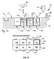
- FIG. 1A 12 shows a receiving device 20 for a total of eight drawers 10a-h arranged in two rows and four columns, as shown in FIG Figure 1B can be seen.
- Each slot 10a-h has an individually height-adjustable substrate plate segment 12a-f.
- Each substrate plate segment 12a-f is individually height-adjustable in a vertical direction 11 within its slot 10a-f.
- the vertical direction 11 for each of the substrate plate segments 12a-f is parallel to one another and perpendicular to the upper surface 13a-f of the substrate plate segments 12a-f, which is horizontal, ie perpendicular to the direction of gravity.
- the evaluations within the receiving device 20 are designed to receive a slot 10a-f in each case, in which a substrate plate segment 12a-f is arranged.
- substrate plate segments can also be inserted into the receiving device 20 which have a larger base area of the substrate plate 12a, for example a base area that is twice as large or four times as large as that in Fig. 1a, b represented substrate plate segments and occupy the corresponding two or four slots.
- a filling block 12g, 12h which does not represent a substrate plate segment and is not used for the manufacture of products, is inserted in the slots 10g and 10h.
- Each substrate plate segment 12a-f can be adjusted in height by means of an actuator 14a-f, which can be, for example, a linear actuator operated by an electric motor.
- the actuator 14a-f is part of the insert 10a-f.
- Each slot 10a-f is surrounded by a housing which is open at the top and has a rectangular, in particular square, cross-section and comprises four walls, as shown by the walls 15a-18a in the slot 10a by way of example.
- the substrate plate segment 12a moves within these walls and in so doing seals off at its lateral edge region with the walls in such a way that coating material which is applied to the substrate plate segment does not come between Substrate plate segment and the walls can pass through.
- the upper end edges of the walls are flush with a surface 21 of the receptacle 20 when the drawers 10a-e are inserted into the receptacle.
- an upper surface of the slide-in units 10g, h is flush with the surface 21 of the receiving device 20.
- a powder applicator 30 which includes a powder feeder 32 from which powder can be dispensed onto the surface 21 of the receptacle and which further includes a pusher 33 which extends along a direction of movement 31 reciprocally across the surface 21 and the substrate plate segments 12a-f or inserts 10a-h can move.
- the slide 33 distributes the powder discharged from the powder conveyor 32 and applies a layer of powder above the substrate plate segments 12a-f.
- the powder application device further comprises a collecting device 34 for excess powder.
- the slide 33 pushes the powder that could not be applied as a powder layer above the substrate plate segments into the collecting device 34 .
- the substrate plate segments 12a-f are set to different heights by means of their actuators 14a-f, i.e. the distance between the upper surface 13a-f of each substrate plate segment and the plane of the surface 21, along which the slide 33 moves and, as a squeegee, the Applying powder is different.
- each powder application process which is started by moving the slider 33 from the in Figure 1A shown right-hand position to a left-hand position in the area of the collecting trough 34 as seen from here, the layer applied during this powder application process above each substrate plate segment 12a-f is cured in predetermined areas by means of a radiation source, here a high-power laser 40.
- This selective curing is based on control data corresponding to the cross-section of a product in each layer applied.
- the cured areas are simultaneously bonded to corresponding underlying areas of the product that have been previously cured.
- the hardening process can take place in particular as selective laser sintering or selective laser melting.
- the beam of the high-power laser 40 is directed with beam steering means in such a way that it hits the predetermined areas of the previously applied layer and selectively cures these areas above all the previously coated substrate plate segments.
- the beam steering means are coupled in terms of signals to a control device.
- Manufacturing data for at least the products to be manufactured at the same time are stored in the control device.
- the production data include in particular position data which characterize the position of a respective product on the substrate plate and geometry data which characterize the geometry of the respective product.
- the geometric data is prepared in such a way that it contains the geometric data of individual cross-sections of the product.
- the respective position of such a cross section and the geometric data stored for this cross section corresponds to the position of the respectively applied material layer from which this product cross section is produced and the geometry of the product in this material layer. In the illustrated embodiment with products standing vertically on the plate, the geometric data therefore correspond to horizontal cross-sectional planes through this product.
- slide 33 moves from the left position to the in Figure 1A right position shown.
- the surface of the selectively hardened areas is ground using a grinding device arranged on the slider, in order to achieve a defined surface for the subsequent coating and hardening process and greater geometric precision of the generatively manufactured component.
- the substrate plate segments 12a-f are lowered by a predefined distance, which corresponds to the layer thickness of the layer subsequently applied.
- the surface of the previously applied layer and the selectively cured areas therein are no longer in alignment with the surface 21 along which the slide 33 moves with a lower squeegee edge, but below by the distance by which the substrate plate segment was lowered the plane of this surface 21.
- a metered quantity of powder is again discharged from the powder feeder 32 onto the surface 21 and, by moving the slide 33 to the left, this powder is applied as a layer above each lowered substrate plate segment.
- the process is repeated until a product is completed within the powder bed applied in layers in this way above a substrate plate segment. That's how it is Figure 1A as can be seen, the time of completion of one or more products above a substrate plate segment in the various drawers 10a-f differs; in the example shown, the product or products on the substrate plate segment 12e in drawer 10e is typically placed before the product or products on the substrate plate segment 12c in the Slot 10c can be completed if the products manufactured therein have approximately the same height.
- the drawer 10a is in the maximum raised position of the substrate plate segment 12a, which corresponds to the start of production.
- That tray can be removed from the cradle 20 and replaced with a new tray with the substrate plate in the uppermost position.
- the products in the removed tray can be detached from the substrate plate after uncured powder material has been removed.
- New products can be manufactured simultaneously on the newly deployed segment. A high level of productivity in the generative manufacturing of products is achieved as a result of the time-delayed but simultaneous construction of products in the device, which is possible in this way.
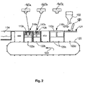
- FIG. 2 shows a second embodiment of the invention, in which several substrate plate segments 112a-c can be coupled as modules 110a-c on an endless conveyor belt 120.
- the actuator within each module is designed to adjust the height of each substrate plate segment 112a-c individually.
- the substrate plate segments 112a and 112b are designed as single segments, whereas the substrate plate segment 112c is designed as a double segment and extends along the conveyor belt 120 over twice the length.
- Each module 110a-c is, in turn, like the drawers according to FIG Figure 1A , B, are provided with side walls within which the substrate plate segments 112a-c can move vertically in an edge sealed manner.
- the peripheral walls terminate with their upper edges flush with a surface 121 onto which powder can in turn be discharged from a powder conveyor 132 .
- the surface 121 is horizontal, i.e.
- a powder bed of different height is set in each individual module 110a-c by gradually lowering the substrate plate segments 112a-c individually, thereby achieving a different production progress, i.e. the layer applied in one operation of the slide 133 is at a distance from the upper surface of the substrate plate segment 112c, which is different from the distance to the surface of the substrate plate segment 112b, which in turn is different from the surface of the substrate plate segment 112a.
- the layer applied in one operation of the slide 133 is at a distance from the upper surface of the substrate plate segment 112c, which is different from the distance to the surface of the substrate plate segment 112b, which in turn is different from the surface of the substrate plate segment 112a.
- the manufacturing progress in the modules 110a-c increases starting from the right in the conveying direction of the conveyor belt 120 to the left, as represented by the arrow 123.
- the conveyor belt is advanced far enough for this module to be removed, or the module is removed and the conveyor belt advanced by the corresponding length of the module.
- a new module can be inserted on the right-hand side adjacent to the illustrated position of the slide 133 and additive manufacturing can be started in this new module.
- the removed module can be further processed in a further production section; in particular, the unhardened powder material can be removed from this and the products manufactured therein can be removed from the substrate plate segment.
- the particular advantage here is that in the finished substrate plate segment, which was previously subjected to simultaneous production with the other substrate plate segments, it is now possible to remove the uncured powder and the finished products without removing the powder from other substrate plate segments must be or the manufacturing process must be stopped in the other substrate plate segments.
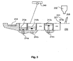
- FIG. 3 shows another embodiment of the invention.
- a plurality of substrate plate segments 212a-c are arranged next to one another and each surrounded by side walls in a sealed manner to the edge regions of each substrate plate segment.
- the side walls terminate with their upper edges flush with a surface 221 along which a slider 233 of a powder application device moves in a direction 231 with its lower edge serving as a squeegee edge.
- the pusher 233 applies a layer of powder above the substrate plate segments 212a-c in one working stroke and pushes excess powder into a collecting trough 234.
- a laser beam source 240 is also provided, which serves to selectively cure predetermined areas of the applied powder layer above each substrate plate segment.
- a controller for the manufacturing device is provided, which is designed in such a way that after each layer application process, predetermined areas above each Substrate plate segment are cured by the laser beam source 240, as previously described.
- a respective actuator 214a-c which is used to individually adjust the height of the substrate plate segments 212a-c and thereby individually change the distance between the upper surface of the respective substrate plate segment and the plane in which the squeegee edge of the slide 133 moves, not part of a Module, which is used in a recording device.
- these actuators 214a-c are integrated into the fixture 220 and the substrate plate segments 212a-c can be detachably coupled to the actuators 214a-c.
- a quasi-continuous production of products can thus be carried out in the same way by means of a generative production process such as SLS (Selective Laser Sintering) or SLM (Selective Laser Melting), with products being produced simultaneously in several substrate plate segments, which are in a different production stage for each substrate plate segment are.
- SLS Selective Laser Sintering
- SLM Selective Laser Melting
- FIGS Figures 1A - 3 show a fourth embodiment of the invention, which is characterized by certain features.
- the embodiment shown is based on the fundamentally similar principle as that in FIGS Figures 1A - 3 embodiments shown and has a substrate plate segment 312a, which can be arranged adjacent to other substrate plate segments (not shown) and can be individually adjusted in its height. It is to be understood that the 4 principle explained below on the in the Figures 1A - 3 illustrated embodiments can be applied.
- FIG. 4 shows a first dosing module 310a, which serves as a dosing platform and is filled with powder before the start of a manufacturing process.
- a height-adjustable base plate 312a is moved to the lowest position within the dosing module.
- a radiator field 380 is arranged above the dosing module 310a, which preheats the powder filled into the dosing module 310a.
- a squeegee 333 is horizontally displaceable along a direction 331 .
- a heating strip 335 is arranged in front of the doctor blade 333 in the direction of movement, which continuously heats the powder moved through the doctor blade or keeps it at the preheated temperature.
- the substrate plate segment 312b Adjacent to the dosing module 310a, the substrate plate segment 312b is arranged in a building module 310b.
- the substrate plate segment 312b is individually and independently of the base plate 312a vertically displaceable in the building module 310a.
- the construction module 310b lies between the dosing module 310a and a collection module 310c, which is used to collect excess powder that the squeegee 333 has pushed over the construction module 310b.
- a base plate 312c is also arranged in the collecting module 310c and can be vertically displaced individually and independently of the base plate 312a and the substrate plate segment 312b.
- the in 4 can also have several such construction modules substrate plate segments instead of the illustrated individual construction module 310b with substrate plate segment 312b. These several building modules would be arranged next to one another in the application direction 313 and the majority of the substrate plate segments would be placed overall between a dosing module 310a arranged at one end with respect to the displacement path 331 of the doctor blade 333 and a collecting module 310c arranged at the other end.
- a radiator array 380c is also arranged above the collection module 310c, which is used to keep the excess material collected in the collection module at a desired temperature.
- a heater 315b is built into the substrate plate segment 312b, which keeps the substrate plate segment and the powder bed arranged on it at a desired temperature.
- the embodiment shown is optimized overall in such a way that a desired, preheated powder state of the powder is achieved before the selective curing process by the radiator fields 380a, b, the heating band 335 and the heater 315b being provided.
- the manufacturing process that can be achieved in the illustrated embodiment consists of a sequence in which first the substrate plate segment 312b is lowered by a certain amount, which corresponds to the layer thickness to be applied, and the platform 312a of the dosing module 315a is raised by a certain amount, which results from the cross section of the platform and calculated based on the powder volume required for the subsequent application process.
- the preheated powder volume from the area of the dosing module is then pushed over the substrate plate segment 312b by horizontal movement of the squeegee 333 and a layer is thereby applied to the substrate plate segment 312b or possibly further substrate plate segments. Excess powder is fed into the collection module.
- a laser 340 is used to cut the powder layer in predetermined areas selectively cured and the cured areas bonded to previously cured areas in the underlying layer.
- the squeegee 333 then moves back, with the previously hardened areas being surface-ground by means of a grinding device, which is arranged in front of the squeegee in the direction of movement from left to right, in order to improve the geometric accuracy of the generatively manufactured product and the connection of the subsequent areas to be cured.
- a grinding device which is arranged in front of the squeegee in the direction of movement from left to right, in order to improve the geometric accuracy of the generatively manufactured product and the connection of the subsequent areas to be cured.
- the process begins again and is repeated until the product to be created is completed above substrate plate segment 312b or any other substrate plate segment arranged in a series of substrate plate segments.
- the laser beam of the laser beam source 340 is guided selectively over each layer in such a way that previously calculated areas of this layer, which correspond to the cross section of the products to be produced in the respective layer on all substrate plate segments, are selectively cured.
- the product can be separated from the substrate plate segment.
- the product can also be manufactured above a substrate plate segment and that several substrate plate segments can also be coated next to one another in different production stages with the single squeegee 333 and selectively cured with the single laser 340 .
- the powder collected in the collecting module 310c can be raised by raising the platform 312c and conveyed back from left to right into the dosing insert by moving the squeegee 333 accordingly, in order to start a new manufacturing process and use the powder again.
- the function of the dosing module and collection module can now be swapped over in the subsequent production process, so that the layer application process now takes place by moving the squeegee from left to right and the grinding process by a correspondingly reverse movement from right to left.
- the mobile unit consisting of the heating strip, doctor blade and grinding device should preferably be designed to be adjustable by 180° around a vertical axis.
- FIG 5 shows another embodiment of the invention.
- the manufacturing arrangement shown comprises a process chamber 1000, which has a first lock 1010 and a second lock 1020.
- Substrate plate segments are fed through the first lock 1010 and placed on a conveyor belt 1030 .
- the substrate plate segments are temporarily stored on this conveyor belt and can be preheated if necessary.
- the substrate plate segments can be placed on a construction platform 420b of a construction insert 410b by means of a robot arm 1040 in order to produce generative products thereon.
- the building block 410b is as before with respect to the embodiment according to FIG 4 explained with regard to the three modules 312a-c shown there, flanked by a dosing insert 410a and a receiving insert 410c and it is to be understood that several substrate plate segments can also be arranged next to each other between the dosing insert and the receiving insert in order to achieve quasi-continuous production in the previously explained way to perform.
- the substrate plate segment 412b can be moved into a lower position. In this lower position, the installation space above the substrate plate segment 412b is connected to a powder suction channel 490, which is embedded in the wall which delimits the installation space as a side wall. The uncured powder can then be sucked out of the area above the substrate plate segment 412b via this powder suction channel 490 .
- the powder suction channel 490 is also designed in such a way that the powder pushed into the collecting tray can also be sucked out through the suction channel 490, it being understood that this may or may not be provided as an optional further function.
- the construction platform can be moved vertically to the uppermost position and the substrate plate segment 412b can again be gripped by the robot arm 1040 and fed to a second conveyor belt 1050.
- the second conveyor belt 1050 is used to convey the substrate plate segment 412b together with the products arranged on it through a tempering oven 1060 in order to subject the products situated thereon to tempering and thereby produce the desired component properties. After the tempering has taken place, the substrate plate segment 412b can be discharged from the process chamber 1000 through the lock 1020 will.
- FIG. 6 shows a further aspect of the device according to the invention and of the method according to the invention.
- each of the substrate plate segments is individually adjustable in height by means of a respective lifting/lowering device 514a-d.
- Both the substrate plate segments in a row and the substrate plate segments in a column can be vertically displaced independently of one another, so that products can be produced generatively in different production stages on each of the substrate plate segments.
- Partition walls are to be provided between the respective substrate plate segments for the purpose of the individual construction of a powder bed above the respective substrate plate segment.
- these partitions are not part of the device, but that the partitions are continuously built up by selective hardening of the powder material in the edge area of the respective substrate plate segments and consequently grow vertically with the generatively manufactured product in the central area of the substrate plate segment.
- partition walls are provided as part of the production device and are arranged in such a way that their upper edge is flush with a plane in which a powder application blade moves.
- the embodiment has an endless conveyor belt 620 along which a plurality of substrate plate segments 612a-e are arranged in the conveying direction 621.
- the substrate plate segments 612a-e are placed such that their top surface lies in a common plane.
- a plurality of coating devices 630a-d are arranged above the substrate plate segments 612a-e.
- the individual coating devices 630a-d each comprise a squeegee 633a-d.
- the bottom edge of the squeegee 633a is spaced one layer from the surface of the substrate plate segments 612a-e.
- the lower edge of squeegee 633b is one layer further away from the surface of the substrate plate segments 612a-e than the previous squeegee 633a, and in the same way the lower edges of the squeegee 633c, d are correspondingly one layer thickness more from the surface of the substrate plate segments compared to the preceding, adjacent squeegee raised.
- the in 7 illustrated embodiment is to be understood in such a way that a large number of individual coating devices a, b, c, d . . . arranged next to one another are provided in such a vertically staggered height arrangement.
- each two layer application devices 633a, b, c . . . there is an area in which the applied layer can be selectively cured by means of a laser 640a, b, c, d.
- a corresponding laser is assigned to each individual coating device.
- the conveyor belt 620 is moved continuously or discontinuously during production in such a way that the upper run moves in the in 7 shown constellation moved from right to left. As a result, a material bed is applied by successive layers above the substrate plate segments 612a, b, c . . . In the same way, the overall height of the products produced additively on the respective substrate plate segments increases.
- the conveyor belt 620 can also be reciprocally moved back and forth several times during a manufacturing process and the multiple powder application devices or the conveyor belt can be displaced vertically in order to apply a number of M x N powder layers during a manufacturing process using a number of N powder application devices, where M corresponds to the number of reciprocating movements of the conveyor belt.
- the N powder applicators are raised or the conveyor belt is lowered by an amount corresponding to N times the layer thickness, in order to achieve that the rightmost and consequently most lowest-lying powder application device in the subsequent application process applies its layer to the layer previously applied by the leftmost and consequently highest arranged powder application device.
- the uncured powder material 590 is suctioned off in the conveying direction to the left of the conveyor belt 520 from the area above a substrate plate segment on which the finished products lie. It is to be understood that such a powder suction takes place only above the substrate plate segment lying furthest to the left, whereas the substrate plate segment lying to the right thereof due to the products that are usually not yet finished there, it is not yet extracted. This can be achieved by means of partitions constructed in parallel between the substrate plate segments.
- the products produced on the substrate plate segment can be separated from it. If necessary, after this separation process, the surfaces of the substrate plate segment can be prepared flat again by means of a device for surface smoothing arranged to the left of the suction device, in particular a milling or grinding station or a device for laser smoothing, in order to subsequently feed the substrate plate segment into a new additive manufacturing process.
- a device for surface smoothing arranged to the left of the suction device, in particular a milling or grinding station or a device for laser smoothing, in order to subsequently feed the substrate plate segment into a new additive manufacturing process.
- the multiple radiation sources can be provided by individual laser sources, respectively, or by one or more laser sources whose beam can be split and consequently directed to a corresponding number of locations. It should also be understood here that the divided beam and the multiple beam paths generated from it can also be guided individually over the respective layers by appropriate radiation guide means in order to selectively cure each layer individually.
- the layer application process for all substrate plate segments takes place in a common first operation, followed by a selective curing process in a second operation. With a corresponding number of individual coating devices, this can take place with continuous movement of the conveyor belt or—with reciprocal movement of the conveyor belt—in a quasi-continuous process.
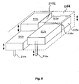
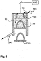
- a further embodiment of the invention can be seen.
- a plurality of substrate plate segments 712a, b are arranged one above the other and the installation space above the respective substrate plate segments is limited by common side walls 715-718.
- the substrate plate segments 712a, b Using a layer application device, layers are applied iteratively in the installation space provided above the uppermost substrate plate segment 712b and selectively cured using a laser beam source. It should be understood here that the layer application process can be carried out in the same way as explained above using a squeegee. This squeegee moves at the in 8 shown embodiment in a horizontal plane, ie perpendicular to the conveying direction of the substrate plate segments 712a, b.
- a new substrate plate segment can be placed on top of it, being coupled in a corresponding manner to a conveyor device for the vertical movement.
- the substrate plate segments with finished products built on them can be removed in a production section arranged below the layer application device and the construction space in which generative production is carried out, in that the powder is sucked off and the products are separated from the substrate plate segment.
- a duct suction can be used, as with respect figure 5 was explained in order to subsequently promote the products in an area that is not limited by side walls and thereby allow the removal of the products or the entire substrate plate segment from the vertical conveyor.
Description
Die Erfindung betrifft ein Verfahren zum Herstellen von Produkten mit individueller Geometrie, insbesondere Zahnersatz oder dentalen Hilfsteilen, mit den Schritten Herstellen mehrerer Produkte auf der Oberfläche einer Substratplatte mittels selektiven Aushärtens, insbesondere mittels selektiven Sinterns oder Schmelzens, bei dem das Material In aufeinanderfolgenden Schichten aufgetragen wird, nach jedem Schichtauftrag ein oder mehrere vorbestimmte Bereiche der aufgetragenen Schicht mittels einer energiereichen Strahlung selektiv ausgehärtet und mit einem oder mehreren Bereichen der darunter liegenden Schicht verbunden werden, wobei die vorbestimmten Bereiche anhand einer Querschnittsgeometrie des Produkts in der jeweiligen Schicht vorbestimmt werden. Ein weiterer Aspekt der Erfindung ist eine Vorrichtung zur Durchführung eines solchen Verfahrens.The invention relates to a method for producing products with an individual geometry, in particular dentures or dental accessories, with the steps of producing a number of products on the surface of a substrate plate by means of selective curing, in particular by means of selective sintering or melting, in which the material is applied in successive layers After each layer application, one or more predetermined areas of the applied layer are selectively cured by means of high-energy radiation and connected to one or more areas of the underlying layer, the predetermined areas being predetermined based on a cross-sectional geometry of the product in the respective layer. A further aspect of the invention is a device for carrying out such a method.
Generative Fertigungsverfahren, d.h. Fertigungsverfahren, bei denen ein Material in einem additiven Herstellungsprozess zu einem individuellen Produkt geformt wird, finden ihre Anwendung im Bereich der Herstellung von Prototypen und haben inzwischen auch in der Produktherstellung, insbesondere bei der Anfertigung individuell geformter Produkte oder von Kleinstserien, ihre Anwendung gefunden. Aus
Neben einem solchen, für Zahnersatz besonders geeigneten selektivem Lasersinter- oder Laserschmelzverfahren (SLS, SLM) für metallische Pulver, können für andere Produkte auch andere generative Fertigungsverfahren geeignet sein, beispielsweise Verfahren, bei denen ein Granulat oder anderes festes Material durch einen hochenergetischen Strahl, wie beispielsweise einen Laserstrahl oder Elektronenstrahl gesintert oder geschmolzen und auf diese Weise verbunden und ausgehärtet wird, oder Verfahren, bei denen ein in fester oder flüssiger Form vorliegender Kunststoff durch einen hochenergetischen Strahl, wie beispielsweise einen Laser- oder gebündelten Lichtstrahl durch Photopolymerisation selektiv ausgehärtet wird.In addition to such a selective laser sintering or laser melting process (SLS, SLM) for metallic powders, which is particularly suitable for dentures, other additive manufacturing processes can also be suitable for other products, for example processes in which a granulate or other solid material is blown through a high-energy beam, such as sintered or melted, for example a laser beam or electron beam, and thus bonded and cured, or processes in which a plastic in solid or liquid form is selectively cured by photopolymerization using a high-energy beam, such as a laser beam or collimated light beam.
Diese generativen Fertigungsverfahren arbeiten regelmäßig solcherart, dass auf einer Substratplatte aufeinanderfolgend Schichten des aushärtbaren Materials aufgetragen werden, beispielsweise indem die Substratplatte sukzessive und diskontinuierlich in ein flüssiges Bad des aushärtbaren Materials abgesenkt wird oder indem mittels einer Pulverauftragsvorrichtung sukzessive Schichten auf der Substratplatte übereinander aufgetragen werden. Nach jedem Schichtauftragsvorgang werden bestimmte Teile der Schicht selektiv ausgehärtet und auf diese Weise das Produkt schichtweise aufgebaut. Nach Fertigstellung des Produkts durch Aushärtung der letzten Schicht können nicht ausgehärtete Bereiche des Materials entfernt und häufig wiederverwendet werden. Das SLS oder SLM-Verfahren ist prinzipiell in
Ein grundsätzliches Problem der generativen Fertigungsverfahren ist die lange Zeitdauer, die zwischen der Erstellung der Fertigungsdaten und der Fertigstellung des Produkts vergeht. Es ist bekannt, auf einer Substratplatte mehrere Produkte gleichzeitig generativ aufzubauen, um auf diese Weise die Anzahl der in einer bestimmten Zeitspanne hergestellten Produkte zu erhöhen. Dieses Vorgehen ist insbesondere bei Produkten mit sehr kleinen Abmessungen in Bezug auf die Abmessungen der Substratplatte sinnvoll und führt zu einer wirksamen Steigerung der Produktivität.A fundamental problem of additive manufacturing processes is the long period of time that elapses between the creation of the manufacturing data and the completion of the product. It is known to generatively build up several products on a substrate plate at the same time in order to increase the number of products manufactured in a certain period of time. This procedure is particularly useful for products with very small dimensions in relation to the dimensions of the substrate plate and leads to an effective increase in productivity.
Aus
Aus
Aus
Aus
Während mit den bekannten Fertigungsverfahren und -vorrichtungen nur individuelle Produkte, deren Größe etwa die Substratplatte einnehmen, in einer sowohl produktiven Fertigungsweise als auch mit einer für jedes Einzelprodukt vertretbaren Gesamtfertigungsdauer hergestellt werden können, ist es für Produkte, deren Abmessungen weitaus kleiner sind als die Substratplatte, nur möglich, die Produktivität durch gemeinsame Fertigung mehrerer Produkte auf einer Substratplatte zu sichern, die Fertigungszeit für ein einzelnes Produkt kann jedoch in diesem Fall nicht auf eine wünschenswert kleine Zeitspanne gebracht werden, sondern wird durch die Erstellung von Fertigungsdaten aller auf der Substratplatte herzustellenden Produkte und die hierauf folgende gleichzeitige Fertigung aller Produkte erhöht.While the known manufacturing methods and devices can only be used to manufacture individual products, the size of which is roughly the size of the substrate plate, both productively and with an overall manufacturing time that is reasonable for each individual product, it is for products whose dimensions are much smaller than the substrate plate , only possible to ensure productivity by jointly manufacturing several products on one substrate plate, but the manufacturing time for a single product cannot be reduced to a desirably short period of time in this case, but is achieved by creating manufacturing data for all products to be manufactured on the substrate plate and subsequent simultaneous manufacture of all products.
Ein weiteres Problem bei der generativen Fertigung von kleinen Produkten, wobei hierunter Produkte verstanden werden sollen, deren Grundfläche kleiner, insbesondere um mindestens eine Größenordnung kleiner ist als die Oberfläche der Substratplatte, besteht darin, dass in vielen Anwendungsbereichen mit individuellen Produktgeometrien die generative Fertigung als Auftragsfertigung erfolgt, wie beispielsweise bei der Herstellung von Zahnersatz in zahntechnischen Laboren. In diesem Fall kommen die einzelnen Aufträge typischerweise nicht gleichzeitig, sondern zeitversetzt beim Benutzer der Fertigungsvorrichtung an. Um in diesem Fall eine hohe Produktivität und Auslastung der Anlage zu erzielen, muss der Benutzer mehrere Aufträge bündeln, um die in den gebündelten Aufträgen enthaltenen Produkte gleichzeitig auf einer Substratplatte zu fertigen. Dies erzeugt jedoch, insbesondere für den zuerst eingegangenen Auftrag, eine erhebliche Verzögerung zwischen Auftragseingang und Fertigstellung des Produkts. Will der Benutzer hingegen jeden Auftrag in der kürzestmöglichen Zeit bedienen und das entsprechende individuelle Produkt fertigen, so ist er gezwungen, den Fertigungsprozess auf einer Substratplatte mit lediglich einem oder einigen wenigen Produkten durchzuführen, was zu einer insgesamt geringen Auslastung der Fertigungsvorrichtung und niedriger Produktivität führt.Another problem in the generative manufacturing of small products, which is to be understood as meaning products whose base area is smaller, in particular by at least one order of magnitude smaller than the surface of the substrate plate, is that in many areas of application with individual product geometries, generative manufacturing is considered to be made-to-order takes place, such as in the manufacture of dentures in dental laboratories. In this case, the individual orders typically do not arrive at the same time but at different times when the user of the manufacturing device receives them. In this case, in order to achieve high productivity and utilization of the plant, the user has to bundle several orders in order to manufacture the products contained in the bundled orders on one substrate plate at the same time. However, this creates a significant delay between the receipt of the order and the completion of the product, especially for the order received first. On the other hand, if the user wants to process each order in the shortest possible time and manufacture the corresponding individual product, he is forced to carry out the manufacturing process on a substrate plate with only one or a few products, which leads to an overall low utilization of the manufacturing device and low productivity.
Es ist eine Aufgabe der Erfindung, die bekannten Fertigungsverfahren dahingehend weiterzuentwickeln, dass auch bei Produkten, deren Abmessungen im Verhältnis zur Substratplattenabmessung klein sind, sowohl eine hohe Produktivität als auch eine geringe Fertigungsdauer für jedes einzelne Produkt zu erreichen. Es ist ein weiteres Ziel der Erfindung, ein Fertigungsverfahren und eine Fertigungsvorrichtung bereitzustellen, welche den Zeitraum zwischen Auftragseingang für ein individuell zu fertigendes, kleines Produkt und Fertigstellung des Produkts zu verkürzen, ohne hierbei die Produktivität des Fertigungsverfahrens bzw. der Fertigungsvorrichtung nachteilig zu beeinflussen.It is an object of the invention to further develop the known production methods such that both high productivity and a short production time for each individual product can be achieved even with products whose dimensions are small in relation to the substrate plate dimensions. It is another object of the invention to provide a manufacturing method and apparatus which shortens the time from receipt of an order for a small product to be individually manufactured to completion of the product without adversely affecting the productivity of the manufacturing method and apparatus.
Diese Aufgabe wird erfindungsgemäß gelöst durch ein Verfahren nach Anspruch 1 oder 2.This object is achieved according to the invention by a method according to
Das erfindungsgemäße Verfahren zeichnet sich dadurch aus, dass eine Substratplatte bereitgestellt wird, auf welcher ein erstes und ein weiteres Produkt in einem ersten und einem entsprechend weiteren Substratplattensegment gleichzeitig generativ hergestellt werden können und diese Substratplattensegmente lösbar miteinander oder mit einem Grundträger verbunden sind. Hierdurch wird es ermöglicht, ein einzelnes Substratplattensegment nach Fertigstellung des darauf aufgebauten Produkts zu entnehmen, um das Produkt von dem Substratplattensegment ablösen zu können, während ein weiteres Produkt auf einem anderen Substratplattensegment weiterhin generativ hergestellt wird.The method according to the invention is characterized in that a substrate plate is provided on which a first and a further product can be produced simultaneously in a first and a corresponding further substrate plate segment and these substrate plate segments are detachably connected to one another or to a base support. This makes it possible to use a single substrate plate segment to be removed after completion of the product built on it, in order to be able to detach the product from the substrate plate segment, while another product on another substrate plate segment continues to be produced generatively.
Insbesondere können beim erfindungsgemäßen Verfahren die Materialschichten auf die zumindest zwei Substratplattensegmente so aufgetragen werden, dass zumindest eine der Materialschichten sich über beide Substratplattensegmente erstreckt. In diesem Fall kann das Verfahren so ablaufen, dass zunächst jeweils eine Materialschicht auf die zumindest zwei Substratplattensegmente aufgetragen wird und diese Materialschicht im Bereich oberhalb beider Substratplattensegmente selektiv ausgehärtet wird.In particular, in the method according to the invention, the material layers can be applied to the at least two substrate plate segments in such a way that at least one of the material layers extends over both substrate plate segments. In this case, the method can proceed in such a way that a material layer is first applied to the at least two substrate plate segments and this material layer is selectively cured in the area above both substrate plate segments.
Die Substratplattensegmente können insbesondere solcherart mit einer einzigen Beschichtungsvorrichtung zusammenwirken, dass auf einem Substratplattensegment ein Produkt in einem ersten Fertigungsstadium aufgebaut wird, beispielsweise mit einer n-ten Schicht oberhalb der Substratplatte und auf einem anderen Substratplattensegment ein anderes Produkt in einem anderen Fertigungsstadium aufgebaut wird, beispielsweise mit einer m-ten aufgebauten Schicht oberhalb der Substratplatte, wobei m ungleich n ist und die n-te und m-te Schicht in einem Arbeitsgang durch die Beschichtungsvorrichtung aufgetragen werden.The substrate plate segments can in particular interact with a single coating device in such a way that a product is built up on a substrate plate segment in a first production stage, for example with an nth layer above the substrate plate and another product is built up on another substrate plate segment in a different production stage, for example with an m-th built-up layer above the substrate plate, where m is not equal to n and the n-th and m-th layers are applied in one operation by the coating device.
Mit dem erfindungsgemäßen Verfahren können somit mit zeitlich gestaffelten Fertigungsstartzeitpunkten mehrere Produkte auf einer Substratplatte hergestellt werden, wobei die Produkte teilweise gleichzeitig hergestellt werden und auch zeitversetzt von der Substratplatte abgelöst werden. Auf diese Weise wird es möglich, die Substratplatte mit dem Ziel einer hohen Produktivität mit mehreren Produkten auszulasten, gleichzeitig aber zu vermeiden, dass der Fertigungsstartzeitpunkt erst nach Fertigstellung aller Fertigungsdaten für alle auf der Substratplatte herzustellenden Produkte liegen kann. Stattdessen kann der Fertigungsstartzeitpunkt für jedes Substratplattensegment individuell bestimmt werden und entsprechend auch ein individueller Fertigungsendzeitpunkt für jedes Substratplattensegment erzielt werden. Auf diese Weise wird die Dauer der Fertigung eines individuellen Produkts entscheidend herabgesetzt.With the method according to the invention, several products can thus be manufactured on a substrate plate with production start times staggered over time, the products being partially manufactured simultaneously and also being detached from the substrate plate at different times. In this way, it is possible to utilize the substrate plate with several products with the aim of high productivity, but at the same time to avoid that the production start time cannot be until after all production data for all products to be manufactured on the substrate plate have been completed. Instead, the production start time can be determined individually for each substrate plate segment and accordingly an individual production end time can also be achieved for each substrate plate segment. In this way, the time it takes to manufacture an individual product is significantly reduced.
Grundsätzlich ist zu verstehen, dass die Substratplatte in zwei, drei oder mehrere Substratplattensegmente unterteilt sein kann. Dabei ist diese Unterteilung insbesondere als tatsächliche physikalische Unterteilung in einzelne Bauelemente zu verstehen, welche zu einer Substratplatte entsprechend zusammengesetzt werden können. Grundsätzlich können auf alle Substratplattensegmente mit einer einzigen, gemeinsamen Schichtauftragsvorrichtung Schichten aufgetragen werden, was aufgrund der damit verbundenen effizienten Fertigung bevorzugt ist. In bestimmten Anwendungen kann es aber vorteilhaft sein, die Substratplattensegmente mittels separater Schichtauftragsvorrichtungen mit Material zu beschichten, wobei auch hier zu verstehen ist, dass beim erfindungsgemäßen Verfahren zwar ein zeitversetzter Fertigungsbeginn und ein entsprechend zeitversetztes Fertigungsende der Produkte auf den verschiedenen Substratplattensegmenten erfolgt, aber auf mehreren Substratplattensegmenten eine simultane Fertigung vorzugsweise mit einem auf allen Substratplattensegmenten simultanen Schichtauftrag und nachfolgender selektiver Aushärtung bestimmter Bereiche zur generativen Herstellung von Produkten zwecks hoher Produktivität stattfindet.In principle, it should be understood that the substrate plate can be divided into two, three or more substrate plate segments. In this case, this subdivision is to be understood in particular as an actual physical subdivision into individual components which can be assembled accordingly to form a substrate plate. In principle, layers can be applied to all substrate plate segments with a single, common layer application device, which is preferred due to the efficient production associated therewith. In certain applications, however, it can be advantageous to coat the substrate plate segments with material by means of separate layer application devices, whereby it should also be understood here that in the method according to the invention the start of production and a corresponding end of production of the products on the various substrate plate segments take place with a time delay, but on several Substrate plate segments, a simultaneous production preferably takes place with a simultaneous layer application on all substrate plate segments and subsequent selective curing of certain areas for the generative manufacture of products for the purpose of high productivity.
Gemäß einer ersten bevorzugten Ausführungsform ist vorgesehen, dass die Substratplattensegmente so nebeneinander bereitgestellt werden, dass zwischen den Substratplattensegmenten kein Material hindurchtreten kann. Insbesondere kann zu diesem Zweck eine entsprechende Abdichtung zwischen den einzelnen Substratplattensegmenten vorgesehen sein oder die Substratplattensegmente in solcher Weise passend aneinandergefügt sein, dass ein Materialdurchtritt zwischen den Substratplattensegmenten nicht möglich ist.According to a first preferred embodiment, it is provided that the substrate plate segments are provided next to one another in such a way that no material can pass between the substrate plate segments. In particular, a corresponding seal can be provided between the individual substrate plate segments for this purpose, or the substrate plate segments can be joined together in such a way that material can not penetrate between the substrate plate segments.
Noch weiter ist es bevorzugt, dass die Substratplattensegmente als Segmente einer Endlosfördervorrichtung ausgebildet sind. Diese Ausgestaltung ermöglicht in besonders effizienter Weise eine kontinuierliche generative Herstellung von Produkten. Die Substratplattensegmente können beispielsweise an einem Endlosförderband befestigt sein oder solcherart miteinander verbunden sein, dass sie in Gestalt einer Gliederkette ein solches Endlosförderband bilden. In diesem Fall können die Substratplattensegmente in aufeinander folgender Weise entlang eines Obertrums und eines Untertrums bewegt werden, wobei während der Bewegung entlang des Obertrums der Schichtauftrag und die selektive Schichtaushärtung erfolgt. Die Entfernung von nicht ausgehärtetem, aufgetragenem Material aus dem Zwischenraum zwischen den hergestellten Produkten und die Entnahme der Produkte kann ebenfalls im Bereich des Obertrums erfolgen, beispielsweise durch entsprechende Absaugeinrichtungen bzw. mechanische Trennvorrichtungen. Es ist aber in gleicher Weise auch möglich, die Entfernung nicht ausgehärteten Materials im Bereich des Untertrums oder bei Übergang vom Obertrum in den Untertrum erfolgen zu lassen, beispielsweise schwerkraftbedingt und die fertig gestellten Produkte dann entweder mitsamt eines Substratplattensegments oder unmittelbar vom Substratplattensegment im Bereich des Untertrums abzunehmen.It is even more preferred that the substrate plate segments are designed as segments of an endless conveyor device. This configuration enables a continuous additive manufacturing of products in a particularly efficient manner. The substrate plate segments can, for example, be attached to an endless conveyor belt or connected to one another in such a way that they form such an endless conveyor belt in the form of a link chain. In this case, the substrate plate segments can be moved in a sequential manner along an upper strand and a lower strand, with the layer application and the selective layer curing taking place during the movement along the upper strand. The removal of non-hardened, applied material from the space between the manufactured products and the removal of the products can also take place in the area of the upper run, for example by appropriate suction devices or mechanical separating devices. However, it is also possible in the same way to have the removal of non-hardened material in the area of the lower run or at the transition from the upper run to the lower run, for example due to gravity, and the finished products then either together with a substrate plate segment or directly from the substrate plate segment in the area of the lower run to decrease.
Weiterhin ist es bevorzugt vorgesehen, dass die Substratplattensegmente solcherart ausgebildet und angeordnet werden, dass das erste Produkt oder eine Gruppe von ersten Produkten auf einem einzigen Substratplattensegment aufgebaut wird und das weitere Produkt oder eine Gruppe von weiteren Produkten auf einem oder mehreren weiteren Substratplattensegmenten aufgebaut wird. Bei dieser Ausgestaltung können einerseits ein oder mehrere Produkte auf einem einzigen Substratplattensegment hergestellt werden, um auf diese Weise mit hoher Produktivität kleine Produkte in einer sehr schnellen Fertigungszeit herzustellen. Andererseits ist es auch möglich, ein einziges Produkt auf mehreren Substratplattensegmenten herzustellen. Dies kann insbesondere dann vorteilhaft sein, wenn größere Produkte mit dem erfindungsgemäßen Verfahren hergestellt werden sollen, also solche Produkte, deren Längsstreckung oder Auflagefläche größer als die Oberfläche eines Substratplattensegments ist. Noch weiter ist vorgesehen, dass eine Gruppe von mehreren Produkten auf zwei oder mehr Substratplattensegmenten hergestellt werden kann. Dies kann insbesondere bei Produkten erforderlich sein, die sich in nur einer bestimmten Richtung sehr weit erstrecken. So kann mit dem erfindungsgemäßen Verfahren ein Produkt hergestellt werden, dessen Länge über mehrere Substratbettensegmente reicht. Wenn mehrere solcher Produkte hergestellt werden sollen, so kann gemäß dieser Fortbildungsform eine Gruppe, von solchen Produkten gebildet werden und diese Gruppe über mehrere Substratplattensegmente erstreckt, dann hergestellt werden.Furthermore, it is preferably provided that the substrate plate segments are designed and arranged in such a way that the first product or a group of first products is built up on a single substrate plate segment and the further product or a group of further products is built up on one or more further substrate plate segments. In this configuration, on the one hand, one or more products can be produced on a single substrate plate segment, in order in this way to produce small products in a very high productivity produce fast production times. On the other hand, it is also possible to produce a single product on a number of substrate plate segments. This can be advantageous in particular when larger products are to be produced using the method according to the invention, ie products whose longitudinal extension or bearing surface is larger than the surface of a substrate plate segment. It is further provided that a group of several products can be produced on two or more substrate plate segments. This can be particularly necessary for products that extend very far in only one specific direction. Thus, with the method according to the invention, a product can be produced whose length extends over several substrate bed segments. If a number of such products are to be manufactured, then, according to this development, a group can be formed by such products and this group can then be manufactured over a number of substrate plate segments.
Noch weiter ist es bevorzugt, dass das Material in einem ersten Fertigungsabschnitt in einem quasi-kontinuierlichen Verfahren auf die Substratplatte aufgetragen und selektiv vorbestimmte Bereiche einer jeweils aufgetragenen Schicht ausgehärtet werden und in einem zweiten Fertigungsabschnitt fertig ausgehärtete Produkte quasi-kontinuierlich entnommen werden. Diese Fertigungsweise ermöglicht eine qualitativ hochwertige generative Herstellung in einem ersten Fertigungsabschnitt und zugleich eine diese generative Fertigung nicht negativ beeinflussende Entnahme von fertig gestellten Produkten in einem zweiten Fertigungsabschnitt, der von dem ersten Fertigungsabschnitt beabstandet ist. Dies kann insbesondere erreicht werden, in dem die Substratplattensegmente an einem Endlosförderband an dem angeordnet sind oder ein solches durch die Substratplattensegmente gebildet wird und die Substratplattensegmente entsprechend von dem ersten in den zweiten Fertigungsabschnitt gefördert werden. Insbesondere kann bei dieser Ausgestaltung der erste Fertigungsabschnitt in einer abgeschlossenen kontrollierten, insbesondere, inerten Atmosphäre gehalten werden, um die für eine generative Fertigung nach bestimmten Verfahren erforderlichen Randbedingungen einstellen zu können, wohingegen im zweiten Fertigungsabschnitt die Produkte ausgeschleust werden, bzw. der zweite Fertigungsabschnitt eine Schleuse beinhaltet oder die Produkte bereits beim Übergang vom ersten in den zweiten Fertigungsabschnitt aus der kontrollierten Atmosphäre ausgeschleust werden.It is even more preferred that the material is applied to the substrate sheet in a quasi-continuous process in a first production section and selectively predetermined areas of each applied layer are cured and completely cured products are removed quasi-continuously in a second production section. This manufacturing method enables high-quality generative manufacturing in a first manufacturing section and, at the same time, removal of finished products in a second manufacturing section, which does not negatively affect this generative manufacturing, which is spaced apart from the first manufacturing section. This can be achieved in particular by arranging the substrate plate segments on an endless conveyor belt or by forming such a belt with the substrate plate segments and conveying the substrate plate segments accordingly from the first to the second production section. In particular, in this configuration, the first production section can be kept in a closed, controlled, in particular inert atmosphere in order to be able to set the boundary conditions required for generative production using certain methods, whereas in the second production section the products are discharged, or the second production section lock or the products are already discharged from the controlled atmosphere during the transition from the first to the second production section.
Weiterhin ist bevorzugt vorgesehen, dass in einem ersten Verfahrensschritt eine Materialschicht oberhalb von zumindest zwei, vorzugsweise mehreren Substratplattensegmenten aufgetragen wird, in einem zweiten Verfahrensschritt die Materialschicht selektiv ausgehärtet wird, und dass der maximale Abstand zwischen dem ersten Substratplattensegment und einer zur Herstellung des ersten Produkts darauf aufgetragenen Schicht in zumindest einem, vorzugsweise mehreren, insbesondere allen Verfahrensstadien sich von dem maximalen Abstand zwischen dem weiteren Substratplattensegment und einer zur Herstellung des weiteren Produkts darauf aufgetragenen Schicht unterscheidet. Bei dieser Ausbildungsform ist zu verstehen, dass ein Verfahrensstadium die Sequenz von Schichtauftrag und selektiver Aushärtung umfasst und folglich wiederholt durchgeführt wird, wodurch aufeinanderfolgende Verfahrensstadien entstehen in einem jeweiligen Verfahrensstadium jeweils ein erster und zweiter Verfahrensschritt aufeinanderfolgend ausgeführt wird und hierbei auf jeweils zumindest zwei, insbesondere mehrere oder alle Substratplattensegmente eine Materialschicht in einem Arbeitsgang aufgetragen wird und diese nachfolgend selektiv ausgehärtet wird, um mehrere Produkte auf den entsprechend mehreren Substratplattensegmenten generativ herzustellen. Erfindungsgemäß wird dabei die Schicht auf die Substratplattensegmente solcherart aufgetragen, dass der Abstand zwischen der aufgetragenen Schicht zu den Substratplattensegmenten unterschiedlich für zumindest zwei, insbesondere für jedes Substratplattensegment ist. Dabei ist zu verstehen, dass dieser maximale Abstand während des Schichtauftrags, und auch oder nur während der selektiven Aushärtung unterschiedlich ist. Dieser Abstand kann sich in nur einem von mehreren aufeinanderfolgenden Verfahrensstadien unterscheiden, die jeweils aus der Abfolge eines Schichtauftrags und der selektiven Aushärtung dieser Schicht bestehen, insbesondere aber kann der Abstand in allen Verfahrensstadien sich unterscheiden, d.h. typischerweise, dass die Summe der aufgetragenen Schichten oberhalb eines Substratplattensegments verschieden ist von der Summe der aufgetragenen Schichten oberhalb eines anderen Substratplattensegments, beispielsweise weil mit dem gemeinsamen Auftrag auf die beiden Substratplattensegmente erst zu einem Zeitpunkt begonnen wurde, wo auf einem der beiden Substratplattensegmente bereits eine oder mehrere Schichten aufgetragen waren. Das Verfahren kann beispielsweise auf solche Weise umgesetzt werden, dass die Substratplattensegmente individuell hinsichtlich ihrer Höhe verfahren werden können, um auf diese Weise zu erreichen, dass zwar eine Schicht auf alle Substratplattensegmente in einer gemeinsamen Ebene aufgetragen wird, gleichwohl aber der Abstand dieser Schicht zu den Substratplattensegmenten unterschiedlich für jedes Substratplattensegment ist, oder indem die Schichtauftragsvorrichtung während des Auftragsvorgangs zwischen den Substratplattensegmenten vertikal verstellt wird.Furthermore, it is preferably provided that in a first method step a material layer is applied above at least two, preferably several, substrate plate segments, in a second method step the material layer is selectively cured, and that the maximum distance between the first substrate plate segment and one for manufacturing the first product thereon applied layer differs in at least one, preferably several, in particular all process stages from the maximum distance between the further substrate plate segment and a layer applied thereto for the production of the further product. In this embodiment, it is to be understood that a process stage comprises the sequence of layer application and selective curing and is consequently carried out repeatedly, resulting in successive process stages. In a respective process stage, a first and second process step is carried out in succession and in this case at least two, in particular several, in each case or a layer of material is applied to all substrate plate segments in one operation and this is subsequently selectively cured in order to generatively produce a number of products on the corresponding number of substrate plate segments. According to the invention, the layer is applied to the substrate plate segments in such a way that the distance between the applied layer and the substrate plate segments is different for at least two, in particular for each, substrate plate segment. It should be understood that this maximum distance is different during the application of the layer and also or only during the selective curing. This distance can differ in only one of several subsequent process stages, each of which consists of the sequence of a layer application and the selective curing of this layer, but in particular the distance can differ in all process stages, i.e. typically that the sum of the layers applied above one Substrate plate segment is different from the sum of the layers applied above another substrate plate segment, for example because the joint application to the two substrate plate segments only started at a point in time when one or more layers had already been applied to one of the two substrate plate segments. The method can be implemented, for example, in such a way that the substrate plate segments can be moved individually with regard to their height in order to achieve in this way that although a layer is applied to all substrate plate segments in a common plane, the distance between this layer and the Substrate plate segments is different for each substrate plate segment, or by the layer application device is vertically adjusted during the application process between the substrate plate segments.
Noch weiter ist es bevorzugt, das Verfahren fortzubilden durch die Schritte Entfernen von auf dem ersten Substratplattensegment angeordnetem Material, welches nicht ausgehärtet wurde, ohne hierbei Material eines weiteren Substratplattensegments zu entfernen, und darauffolgendes Entfernen von dem auf dem weiteren Substratplattensegment angeordnetem Material, welches nicht ausgehärtet wurde. Für die erfindungsgemäße, quasi-kontinuierliche generative Fertigung ist es an der Entnahmestelle besonders vorteilhaft, wenn das Entfernen des nicht ausgehärteten Materials in solcher Weise erfolgen kann, dass ein benachbarter Bereich hierdurch nicht beeinflusst wird und das nicht ausgehärtete Material in diesem benachbarten Bereich stehen bleibt. Während der generativen Fertigung hat das nicht ausgehärtete Material eine Stützfunktion und dient dazu, darüber liegende Schichten aufzunehmen und zu tragen. Das nicht ausgehärtete Material darf daher in der Regel nicht entfernt werden, bevor das Produkt nicht vollständig aufgebaut und ausgehärtet worden ist. Um nun aber unter einer solchen Vorgabe die Notwendigkeit zu verhindern, dass fertig gestellte Produkte zunächst eine längere, der Prozesssicherheit dienende Strecke zurücklegen müssen, bis sie zu der Entnahmestelle gelangen, an dem das nicht ausgehärtete Material entfernt wird, ist es vorteilhaft, wenn die Materialentfernungsvorrichtung die Materialentfernung bewerkstelligen kann, ohne das unmittelbar benachbarte Substratplattensegment hierbei zu beeinflussen. Dies ermöglicht die schnelle und quasi-kontinuierliche Fertigung und vermeidet die Bereitstellung eines Sicherheitsabstandes zwischen Schichtauftragsvorrichtung und Materialentfernungsvorrichtung.It is even more preferred to develop the method further by the steps of removing material which is arranged on the first substrate plate segment and which has not been cured, without thereby removing material of a further substrate plate segment, and subsequent removal of the material arranged on the further substrate plate segment, which has not been cured. For the quasi-continuous generative manufacturing according to the invention, it is particularly advantageous at the removal point if the uncured material can be removed in such a way that a neighboring area is not affected and the uncured material remains in this neighboring area. During additive manufacturing, the uncured material has a support function and serves to accommodate and carry overlying layers. The uncured material should therefore generally not be removed before the product has been fully built up and cured. However, in order to prevent the necessity under such a specification that finished products first have to cover a longer distance, which serves to ensure process reliability, until they reach the removal point at which the uncured material is removed, it is advantageous if the material removal device can accomplish the material removal without affecting the immediately adjacent substrate plate segment here. This enables rapid and quasi-continuous production and avoids providing a safety distance between the layer application device and the material removal device.
Weiterhin ist es bevorzugt, dass in einer ersten Phase des Herstellungsvorgangs nur Schichtbereiche einer Schicht selektiv ausgehärtet werden, welche zur Herstellung des ersten Produktes dienen und in einer letzten Phase des Herstellungsvorgangs nur Schichtbereiche einer Schicht selektiv ausgehärtet werden, welche zur Herstellung des weiteren Produktes dienen und vorzugsweise in einer zwischen der ersten und der letzten Phase liegenden mittleren Phase des Herstellungsvorgangs Schichtbereiche einer Schicht ausgehärtet werden, welche zur Herstellung des ersten und des weiteren Produktes dienen. Mit der so erreichten, quasi-kontinuierlichen und simultanen Fertigung von Produkten in unterschiedlichen Fertigstellungsstadien wird ein produktives und schnelles Verfahren zur individuellen Herstellung von kleinen Produkten mittels eines generativen Fertigungsverfahrens erzielt.Furthermore, it is preferred that in a first phase of the manufacturing process only layer areas of a layer are selectively cured which are used to manufacture the first product and in a final phase of the manufacturing process only layer areas of a layer are selectively cured which are used to manufacture the further product and preferably in a middle phase of the production process lying between the first and the last phase, layer regions of a layer are cured, which are used for the production of the first and the further product. With the quasi-continuous and simultaneous production of products in different stages of completion achieved in this way, a productive and rapid process for the individual production of small products using an additive manufacturing process is achieved.
Gemäß einer weiteren bevorzugten Ausführungsform ist vorgesehen, dass zwischen den Substratplattensegmenten eine Trennwand bereitgestellt wird, welche den oberhalb jedes Substratplattensegments bestehenden Bauraum von dem oberhalb eines benachbarten Substratplattensegments bestehenden Bauraum abtrennt. Eine solche Trennwand ermöglicht oder vereinfacht die Entfernung von nicht ausgehärtetem Material oberhalb von einem Substratplattensegment, ohne hierbei das nicht ausgehärtete Material in einem hierzu benachbarten Substratplattensegment zu beeinflussen. Dabei ist zu verstehen, dass eine solche Trennwand als Bestandteil der Fertigungsvorrichtung bereitgestellt werden kann und in diesem Fall beispielsweise so ausgeführt werden kann, dass sie simultan zum Schichtauftrag nachgeführt wird, um jeweils eine exakte Höhe oder etwas weniger als diese exakte Höhe aufzuweisen, die der oberen Schichtfläche des Materialauftrags im Bereich zwischen zwei Substratplattensegmenten entspricht.According to a further preferred embodiment, it is provided that a partition is provided between the substrate plate segments, which partition separates the installation space above each substrate plate segment from the installation space above an adjacent substrate plate segment. Such a partition enables or simplifies the removal of uncured material above a substrate plate segment without affecting the uncured material in a substrate plate segment adjacent thereto. It is to be understood that such a partition wall can be provided as part of the production device and in this case can be designed in such a way, for example, that it is tracked simultaneously with the layer application in order to have an exact height or slightly less than this exact height that the corresponds to the upper layer surface of the material application in the area between two substrate plate segments.
Dabei kann insbesondere vorgesehen sein, dass die Trennwand durch Aushärten des aufgetragenen Materials während des Herstellungsvorgangs des Produkts hergestellt wird. Mit dieser Fortbildungsform wird jeweils am Rand eines Substratplattensegments während des Fertigungsvorgangs aus dem aufgetragenen Material eine solche Trennwand hergestellt. Diese Vorgehensweise hat den Vorteil, dass auf konstruktiv aufwändige Trennwandnachführungen verzichtet werden kann. Stattdessen wird entlang des Randbereichs eines Substratplattensegments eine entsprechende Trennwand aufgebaut, die entsprechend bei jedem Schichtauftrag höher wächst und auf diese Weise zur Gesamthöhe des Materialschichtbettes nachgeführt wird. Die Trennwand kann dann bei Entfernen der Produkte von dem Substratplattensegment oder im Zuge der Entfernung von nicht ausgehärtetem Material von dem benachbarten Substratplattensegment entfernt werden.It can be provided in particular that the partition is produced by curing the applied material during the manufacturing process of the product. With this further development, such a partition wall is produced from the applied material at the edge of a substrate plate segment during the production process. This procedure has the advantage that there is no need for structurally complex adjustments to the partition wall. Instead, a corresponding partition wall is built up along the edge area of a substrate plate segment, which grows higher with each layer application and in this way is tracked to the total height of the material layer bed. The dividing wall can then be removed when removing the products from the substrate plate segment or in the course of removing uncured material from the adjacent substrate plate segment.
Die beiden vorgenannten Ausführungsformen können weiter fortgebildet werden, indem die Trennwand zwischen zwei Substratplattensegmenten mit zumindest einem der beiden Substratplattensegmenten verbunden ist. Durch Verbindung der Trennwand mit beiden Substratplattensegmenten, welche sie voneinander abtrennt, kann zugleich auch eine sichere Abdichtung gegen Materialdurchtritt zwischen den Substratplattensegmenten erreicht werden. Die Verbindung kann hierbei durch generativen Aufbau der Trennwand auf einem oder beiden Substratplattensegmenten oder durch entsprechend konstruktive Verbindung eines zur Vorrichtung gehörenden Trennwandbauteils erzielt werden. Gemäß einer weiteren bevorzugten Ausführungsform ist vorgesehen, dass jedes Substratplattensegment individuell in Bezug auf die Schichtauftragsvorrichtung solcherart verfahren wird, dass der Abstand senkrecht zur Oberfläche der Substratplatte und der mit einer Schichtauftragsvorrichtung aufgetragenen Schicht verändert wird und die resultierende Höhe des Materialbetts auf einem Substratplattensegment verschieden von der Höhe des Materialbetts auf einem anderen Substratplattensegment ist. Gemäß dieser Ausführungsform kann jedes Substratplattensegment beispielsweise mittels eines Aktuators, der wechselweise auf die Substratplattensegmente einwirkt oder mittels mehrerer Aktuatoren, von denen jeder für jeweils ein Substratplattensegment bereitgestellt ist, individuell in seiner Höhe verfahren werden. Hierdurch wird erreicht, dass die Substratplattensegmente auf unterschiedlichen Höhen platziert werden können, um dann nachfolgend eine Materialschicht in eine Ebene oberhalb der Substratplattensegmente aufzutragen. Diese Materialschicht liegt dann in individuell verschiedenem Abstand zu den jeweiligen Substratplattensegmenten, d.h. insbesondere in individuellem Abstand zu der Ebene der Oberfläche der Substratplattensegmente, auf welche die erste Materialschicht auf das jeweilige Substratplattensegment aufgetragen worden ist. Die Ausführungsform eignet sich, um ein Produkt in einem ersten Verfahrensstadium auf einem ersten Substratplattensegment und ein anderes Produkt in einem anderen Fertigungsstadium auf einem anderen Substratplattensegment bei gemeinsamem Schichtauftrag auf die beiden Substratplattensegmente generativ herzustellen und kann auf entsprechend mehrere Substratplattensegmente mit entsprechend mehreren Produkten in unterschiedlichen Verfahrensstadien angewendet werden.The two aforementioned embodiments can be further developed in that the partition wall between two substrate plate segments is connected to at least one of the two substrate plate segments. By connecting the dividing wall to the two substrate plate segments, which separates them from one another, a secure seal against the passage of material between the substrate plate segments can also be achieved at the same time. The connection can be achieved here by generative construction of the partition on one or both substrate plate segments or by appropriate structural connection of a partition wall component belonging to the device. According to a further preferred embodiment, it is provided that each substrate plate segment is moved individually in relation to the layer application device in such a way that the distance perpendicular to the surface of the substrate plate and the layer applied with a layer application device is changed and the resulting height of the material bed on a substrate plate segment is different from the Height of the material bed is on another substrate plate segment. According to this embodiment, the height of each substrate plate segment can be moved individually, for example by means of an actuator that acts alternately on the substrate plate segments or by means of a plurality of actuators, each of which is provided for one substrate plate segment. The result of this is that the substrate plate segments can be placed at different heights in order to then subsequently apply a layer of material in a plane above the substrate plate segments. This material layer is then at an individually different distance from the respective substrate plate segments, ie in particular at an individual distance from the plane of the surface of the substrate plate segments on which the first material layer is placed on the respective substrate plate segment has been applied. The embodiment is suitable for generatively producing a product in a first process stage on a first substrate plate segment and another product in a different production stage on another substrate plate segment with a common layer application on the two substrate plate segments and can be applied to a corresponding number of substrate plate segments with a corresponding number of products in different process stages be applied.
Weiter ist es bevorzugt, dass vor jedem Materialauftrag die ausgehärteten Bereiche der zuvor aufgetragenen Schicht oberflächlich beschliffen werden. Durch eine solche Oberflächenbearbeitung, die insbesondere als Beschleifung, aber auch durch andere spanende Fertigungsverfahren mit geometrisch definierter oder geometrisch undefinierter Schneide erfolgen kann, wird die geometrische Präzision des generativen Fertigungsverfahrens weiter erhöht. Insbesondere wird durch eine solche spanende Bearbeitung eine definierte Auflagefläche und Verbindungsstelle für die darüber liegende Schicht und die darin auszuhärtenden Bereiche bereitgestellt. Zudem wird durch die spanende Bearbeitung eine definierte Schichtdicke eingestellt, was für ein reproduzierbares geometrisches Fertigungsergebnis vorteilhaft ist.Furthermore, it is preferred that the hardened areas of the previously applied layer are surface-ground before each application of material. The geometric precision of the generative manufacturing process is further increased by such surface processing, which can be carried out in particular as grinding, but also by other machining manufacturing processes with a geometrically defined or geometrically undefined cutting edge. In particular, such a machining operation provides a defined bearing surface and connection point for the layer above and for the areas to be cured therein. In addition, a defined layer thickness is set by the machining, which is advantageous for a reproducible geometric manufacturing result.
Noch weiter ist es bevorzugt, dass zur Aushärtung des ersten und des zumindest einen weiteren Produkts, insbesondere aller weiteren Produkte eine einzige Strahlungsquelle, insbesondere ein einziger Strahlengang einer einzigen Strahlungsquelle genutzt wird. Grundsätzlich ist zu verstehen, dass zur Beschleunigung des Fertigungsvorgangs auch auf mehrere Strahlenquellen oder mehrere Strahlengänge einer einzigen Strahlenquelle zurückgegriffen werden kann. Das erfindungsgemäße Herstellungsverfahren zeichnet sich aber insbesondere dadurch aus, dass es zwar mehrere Produkte gleichzeitig herstellt und diese Produkte in unterschiedlichen Fertigungsstadien sind, d.h. insbesondere aus einer unterschiedlichen Anzahl von Schichten aufgebaut sind. Besonders ist hierbei aber, dass sowohl der Auftrag einer Schicht durch eine einzige Schichtauftragsvorrichtung für alle Substratplattensegmente und darauf aufgebauten, zu fertigenden Produkte erfolgen kann und dass darüber hinaus auch die Aushärtung der bestimmten Bereiche einer Schicht für alle zu fertigenden Produkte durch eine einzige Strahlungsquelle erfolgen kann.It is even more preferred that a single radiation source, in particular a single beam path of a single radiation source, is used to cure the first and the at least one further product, in particular all further products. In principle, it should be understood that multiple radiation sources or multiple beam paths of a single radiation source can also be used to speed up the manufacturing process. However, the production method according to the invention is characterized in particular by the fact that it produces several products at the same time and these products are in different production stages, i.e. in particular are made up of a different number of layers. What is special here, however, is that both the application of a layer can be carried out by a single layer application device for all substrate plate segments and products to be manufactured built on them, and that the specific areas of a layer for all products to be manufactured can also be cured by a single radiation source .
Gemäß einer weiteren bevorzugten Ausführungsform ist vorgesehen, dass jedes Substratplattensegment während des Herstellungsvorgangs mittels einer Hubvorrichtung in einer vertikalen Richtung angehoben und abgesenkt wird und die Hebe- und Senkbewegung der Substratplattensegmente unabhängig voneinander ist. Die unabhängige Hebe- und Senkbewegung kann insbesondere durch jeweils einen auf mehrere Substratplattensegmente einwirkenden Aktuator bewirkt werden oder durch jeweils einen Aktuator, der jeweils einem Substratplattensegment zugeordnet ist.According to a further preferred embodiment it is provided that each substrate plate segment is raised and lowered in a vertical direction during the manufacturing process by means of a lifting device and the lifting and lowering movement of the substrate plate segments is independent of one another. The independent lifting and lowering movement can be brought about in particular by an actuator acting on a plurality of substrate plate segments or by an actuator in each case which is assigned to one substrate plate segment in each case.
Noch weiter ist es bevorzugt, dass mehrere Substratplattensegmente in einem Arbeitsgang mit einer einzigen Materialauftragsvorrichtung mit Material beschichtet werden. Diese Fortbildung ermöglicht eine effizient arbeitende Schichtauftragsvorrichtung bei zugleich individuellem Fertigungsfortschritt der jeweiligen Produkte, die auf den jeweils mehreren Substratplattensegmenten hergestellt werden.It is even more preferred that a plurality of substrate plate segments are coated with material in one operation using a single material application device. This development enables an efficiently working layer application device with at the same time individual production progress of the respective products that are produced on the respective several substrate plate segments.
Schließlich kann das Verfahren durch die Schritte fortgebildet werden: Aufbringen einer n-ten Materialschicht auf eine Substratträgerplatte, selektives Aushärten von Teilen der Materialschicht mittels Einwirken einer energiereichen Strahlung, insbesondere einer Laserstrahlung, auf diese Teile der Materialschicht, Führen der energiereichen Strahlung über die n-te Materialschicht nach Führungsdaten, welche aus den geometrischen Daten einer x-ten Querschnittsfläche eines ersten Produkts ermittelt wurden, Aufbringen einer n+1-ten Materialschicht auf die n-te Materialschicht, Führen der energiereichen Strahlung über die n+1-te Materialschicht nach Führungsdaten, welche aus den geometrischen Daten einer x+1-ten Querschnittsfläche des ersten Produkts ermittelt wurden, Führen der energiereichen Strahlung über die n-te Materialschicht nach Führungsdaten, welche aus den geometrischen Daten einer y-ten Querschnittsfläche eines zweiten Produkts ermittelt wurden, und Führen der energiereichen Strahlung über die n+1-te Materialschicht nach Führungsdaten, welche aus den geometrischen Daten einer y+1-ten Querschnittsfläche des zweiten Produkts ermittelt wurden wobei, x ungleich y ist. Bei dieser Fortbildungsform werden zumindest zwei Produkte hergestellt, indem sie in einem gemeinsamen Schichtauftrag in zwei unterschiedlichen Schichtbereichen ein und derselben Schicht einer selektiven Aushärtung unterzogen werden, wobei in dieser Schicht in den Produkten selbst unterschiedliche Höhen gegenüber der Substratplatte dargestellt sind.Finally, the method can be further developed through the steps: application of an nth material layer to a substrate carrier plate, selective curing of parts of the material layer by means of the action of high-energy radiation, in particular laser radiation, on these parts of the material layer, guiding the high-energy radiation over the n- th material layer according to guidance data, which were determined from the geometric data of an xth cross-sectional area of a first product, applying an n+1th material layer to the nth material layer, guiding the high-energy radiation over the n+1th material layer according to guidance data , which have been determined from the geometric data of an x+1-th cross-sectional area of the first product, guiding the high-energy radiation over the n-th material layer according to guiding data which have been determined from the geometric data of an y-th cross-sectional area of a second product, and guiding the energetic ray ment over the n+1-th layer of material according to guidance data, which were determined from the geometric data of a y+1-th cross-sectional area of the second product, where x is not equal to y. In this development, at least two products are produced by subjecting them to selective curing in a common layer application in two different layer areas of one and the same layer, different heights being shown in the products themselves in this layer compared to the substrate plate.
Ein weiterer Aspekt der Erfindung ist eine Vorrichtung nach Anspruch 11 oder 12.Another aspect of the invention is an apparatus according to claim 11 or 12.
Die erfindungsgemäße Vorrichtung zeichnet sich dadurch aus, dass oberhalb einer Substratplatte eine Materialauftragsvorrichtung angeordnet ist, mit der in einem Arbeitsgang eine Materialschicht auf alle Substratplattensegmente der Substratplatte aufgetragen werden kann. Weiterhin ist eine Strahlungsquelle oberhalb der Substratplatte bereitgestellt. Materialauftragsvorrichtung und Strahlungsquelle werden mittels einer Fertigungssteuerungseinrichtung so angesteuert, dass die im ersten Arbeitsgang aufgetragene Materialschicht in einem weiteren Arbeitsgang mit der Strahlungsquelle selektiv ausgehärtet werden kann, in mehrere Segmente unterteilt ist. Die Segmente können lösbar miteinander verbunden sein, worunter zu verstehen ist, dass jeweils ein Segment mit nur einem benachbarten Segment verbunden ist oder ein Segment mit mehreren umgebenden Segmenten verbunden sein kann. Alternativ ist auch vorgesehen, dass die Segmente nebeneinander angeordnet sind und jedes Segment lösbar mit einem Grundträger verbunden ist. Mit der erfindungsgemäßen Vorrichtung wird es auf diese Weise möglich, mehrere Produkte verteilt auf mehrere Substratplattensegmente generativ zu fertigen und hierbei die Substratplattensegmente solcherart in ihrer Höhe relativ zueinander zu bewegen, dass die Produkte in unterschiedlichen Fertigungsstadien auf den unterschiedlichen Substratplattensegmenten hergestellt werden und das oder die Produkte, die auf einem ersten Substratplattensegment hergestellt worden sind, mit dem Substratplattensegment zu entnehmen und hiervon abzulösen, bevor ein oder mehrere Produkte von einem anderen Substratplattensegment entnommen und abgelöst werden.The device according to the invention is characterized in that a material application device is arranged above a substrate plate, with which a material layer can be applied to all substrate plate segments of the substrate plate in one operation. Furthermore, a radiation source is provided above the substrate plate. Material application device and radiation source are controlled by a production control device so that the material layer applied in the first operation can be selectively cured in a further operation with the radiation source, is divided into several segments. The segments can be releasably connected to one another, by which is meant that one segment is connected to only one adjacent segment, or one segment can be connected to a plurality of surrounding segments. Alternatively, it is also provided that the segments are arranged next to one another and each segment is detachably connected to a base support. With the device according to the invention, it is possible in this way to generatively manufacture a number of products distributed over a number of substrate plate segments and to move the height of the substrate plate segments relative to one another in such a way that the products are manufactured in different manufacturing stages on the different substrate plate segments and the product or products , which have been produced on a first substrate plate segment, are to be removed and detached from the substrate plate segment before one or more products are removed and detached from another substrate plate segment.
Die erfindungsgemäße Vorrichtung kann fortgebildet werden, indem die Materialauftragsvorrichtung zum simultanen Auftragen einer Materialschicht oberhalb einer Anzahl der mehreren Substratplattensegmente in einem Arbeitsgang ausgebildet ist.The device according to the invention can be further developed in that the material application device is designed for the simultaneous application of a material layer above a number of the plurality of substrate plate segments in one operation.
Weiterhin kann die erfindungsgemäße Vorrichtung fortgebildet werden, indem die Substratplattensegmente und die Materialzufuhreinrichtung mittels eines oder mehrerer Aktuatoren solcherart relativ individuell zueinander bewegbar sind, dass der Abstand zwischen der Ebene der Oberfläche eines ersten Substratplattensegments und eines zur Herstellung eines ersten Produkts darauf aufgetragenen Schichtbereichs der Materialschicht sich von dem Abstand zwischen der Ebene der Oberfläche eines weiteren Substratplattensegments und eines zur Herstellung des weiteren Produkts darauf aufgetragenen Schichtbereichs der selben Materialschicht unterscheidet.Furthermore, the device according to the invention can be further developed in that the substrate plate segments and the material supply device can be moved individually relative to one another by means of one or more actuators in such a way that the distance between the plane of the surface of a first substrate plate segment and a layer region of the material layer applied thereto for the production of a first product changes differs from the distance between the plane of the surface of a further substrate plate segment and a layer region of the same material layer applied thereto for the production of the further product.
Noch weiter kann die erfindungsgemäße Vorrichtung fortgebildet werden durch eine Materialentfernungsvorrichtung, insbesondere eine Material-Absaugeinrichtung, wobei die Materialentfernungsvorrichtung ausgebildet ist, um nicht ausgehärtetes Material aus einem ein gefertigtes Produkt umgebenden Bereich zu entfernen, und so angeordnet ist, dass sie das Material auf einem ersten Substratplattensegment entfernen kann und hierbei das Material auf einem weiteren, hierzu benachbarten Substratplattensegment belassen kann.The device according to the invention can be further developed by a material removal device, in particular a material suction device, wherein the material removal device is designed to remove uncured material from an area surrounding a manufactured product and is arranged in such a way that it removes the material on a first Can remove substrate plate segment and in doing so can leave the material on another substrate plate segment adjacent thereto.
Gemäß einer weiteren bevorzugten Ausführungsform ist vorgesehen, dass die erfindungsgemäße Vorrichtung eine Steuerung aufweist zur Ansteuerung der Führungsvorrichtung des hochenergetischen Strahls, welche ausgebildet ist, um die Führungsvorrichtung so anzusteuern, dass in einer ersten Phase des Herstellungsvorgangs nur Schichtbereiche einer Schicht selektiv ausgehärtet werden, welche zur Herstellung eines ersten Produktes auf einem ersten Substratplattensegment dienen, in einer letzten Phase des Herstellungsvorgangs nur Schichtbereiche einer Schicht selektiv ausgehärtet werden, welche zur Herstellung eines weiteren Produktes auf einem weiteren Substratplattensegment dienen und in einer zwischen der ersten und der letzten Phase liegenden mittleren Phase des Herstellungsvorgangs Schichtbereiche einer Schicht ausgehärtet werden, welche zur Herstellung des ersten und des weiteren Produktes dienen.According to a further preferred embodiment, it is provided that the device according to the invention has a control for controlling the guiding device of the high-energy beam, which is designed to control the guiding device in such a way that in a first phase of the production process only layer regions of a layer are selectively cured, which production of a first product on a first substrate plate segment, in a last phase of the production process only layer regions of a layer are selectively cured, which serve for the production of a further product on a further substrate plate segment and in a middle phase of the production process lying between the first and the last phase Layer areas of a layer are cured, which are used to produce the first and the other product.
Die erfindungsgemäße Vorrichtung kann weiter fortgebildet werden durch eine Steuerung zur Ansteuerung der Materialauftragsvorrichtung und/oder zur Ansteuerung von zumindest einem Aktuator zur relativen Bewegung zwischen den Substratplattensegmenten und der Materialauftragsvorrichtung, die ausgebildet ist, um die sich nach Auftrag aller Materialschichten einstellende Höhe des Materialbetts auf einem ersten Substratplattensegment verschieden von der nach Auftrag aller Materialschichten resultierende Höhe des Materialbetts auf einem anderen Substratplattensegment bereitzustellen. Hiermit können auf verschiedenen Substratplattensegmenten Produkte unterschiedlicher Bauhöhe hergestellt und diese gleichzeitig fertiggestellt werden.The device according to the invention can be further developed by a controller for activating the material application device and/or for activating at least one actuator for the relative movement between the substrate plate segments and the material application device, which is designed to adjust the height of the material bed after all layers of material have been applied on a first substrate plate segment different from the height of the material bed resulting after application of all material layers on another substrate plate segment. With this, products of different heights can be produced on different substrate plate segments and these can be finished at the same time.
Weiterhin ist bevorzugt vorgesehen, dass an der Materialauftragsvorrichtung eine Bearbeitungsvorrichtung zum Abtragen eines Oberflächenanteils der ausgehärteten Materialbereiche, vorzugsweise zum oberflächlichen Beschleifen, der ausgehärteten Materialbereiche einer zuvor aufgetragenen Materialschicht angeordnet ist.Furthermore, it is preferably provided that a processing device for removing a surface portion of the hardened material areas, preferably for superficial grinding, of the hardened material areas of a previously applied material layer is arranged on the material application device.
Noch weiter ist bevorzugt vorgesehen, dass die Substratplattensegmente an einem Endlos-Förderband angeordnet sind, welches teilweise oder vollständig in einer Bearbeitungskammer verläuft, die gegen die Umgebung soweit abgedichtet ist, dass darin eine kontrollierte, insbesondere inerte Atmosphäre eingestellt werden kann.It is also preferably provided that the substrate plate segments are arranged on an endless conveyor belt which runs partially or completely in a processing chamber which is sealed off from the environment to such an extent that a controlled, in particular inert atmosphere can be set in it.
Weiter fortgebildet werden kann die Vorrichtung durch zumindest eine Hubeinrichtung, welche mit jedem Substratplattensegment gekoppelt ist oder gekoppelt werden kann, um während des Herstellungsvorgang das jeweilige Substratplattensegment unabhängig von den anderen Substratplattensegmente in einer vertikalen Richtung anzuheben und abzusenken.The device can be further developed by at least one lifting device which is or can be coupled to each substrate plate segment in order to raise and lower the respective substrate plate segment in a vertical direction independently of the other substrate plate segments during the manufacturing process.
Noch weiter kann die erfindungsgemäße Vorrichtung fortgebildet werden durch eine einzige Strahlungsquelle, die, insbesondere mittels eines einzigen Strahlengangs, zur Aushärtung der auf allen Substratplattensegmenten hergestellten Produkte genutzt wird.The device according to the invention can be further developed by a single radiation source, which is used, in particular by means of a single beam path, for curing the products produced on all substrate plate segments.
Noch weiter kann die erfindungsgemäße Vorrichtung fortgebildet werden durch eine zwischen den Substratplattensegmenten angeordnete Trennwand, welche den oberhalb jedes Substratplattensegments bestehenden Bauraum von dem oberhalb eines benachbarten Substratplattensegments bestehenden Bauraum abtrennt.The device according to the invention can be developed even further by a partition arranged between the substrate plate segments, which separates the installation space above each substrate plate segment from the installation space above an adjacent substrate plate segment.
Es ist bevorzugt weiter vorgesehen, dass die Trennwand zwischen zwei Substratplattensegmenten mit zumindest einem der beiden Substratplattensegmenten verbunden oder gegen dieses Substratplattensegment solcherart abgedichtet ist, dass kein Material zwischen Trennwand und Substratplattensegment hindurchtreten kann.It is preferably further provided that the partition between two substrate plate segments is connected to at least one of the two substrate plate segments or is sealed against this substrate plate segment in such a way that no material can pass between partition and substrate plate segment.
Gemäß einer weiteren bevorzugten Ausführungsform zeichnet sich die Vorrichtung aus durch eine Steuerung zur Ansteuerung der Führungsvorrichtung des hochenergetischen Strahls, welche ausgebildet ist, um die Führungsvorrichtung so anzusteuern, dass die Trennwand während des Herstellungsvorgangs des Produkts durch Aushärten des aufgetragenen Materials hergestellt wird.According to a further preferred embodiment, the device is characterized by a controller for controlling the guiding device of the high-energy beam, which is designed to control the guiding device in such a way that the partition wall is produced during the manufacturing process of the product by curing the applied material.
Schließlich kann die erfindungsgemäße Vorrichtung fortgebildet werden durch eine Steuerung zur Ansteuerung der Führungsvorrichtung des hochenergetischen Strahls, welche ausgebildet ist, um die energiereiche Strahlung über die n-te Materialschicht nach Führungsdaten zu führen, welche aus den geometrischen Daten einer x-ten Querschnittsfläche eines ersten Produkts ermittelt wurden, um Teile der n-ten Materialschicht mittels Einwirken einer energiereichen Strahlung auszuhärten, die energiereiche Strahlung über eine n+1-te Materialschicht nach Führungsdaten zu führen, welche aus den geometrischen Daten einer x+1-ten Querschnittsfläche des ersten Produkts ermittelt wurden, um Teile der n+1-ten Materialschicht mittels Einwirken der energiereichen Strahlung auszuhärten, die energiereiche Strahlung über die n-te Materialschicht nach Führungsdaten zu führen, welche aus den geometrischen Daten einer y-ten Querschnittsfläche eines zweiten Produkts ermittelt wurden, um Teile der n-ten Materialschicht mittels Einwirken der energiereichen Strahlung auszuhärten und die energiereiche Strahlung über die n+1-te Materialschicht nach Führungsdaten zu führen, welche aus den geometrischen Daten einer y+1-ten Querschnittsfläche des zweiten Produkts ermittelt wurden, um Teile der n+1-ten Materialschicht mittels Einwirken der energiereichen Strahlung auszuhärten, wobei x ungleich y ist.Finally, the device according to the invention can be further developed by a controller for controlling the guiding device of the high-energy beam, which is designed to guide the high-energy radiation over the nth material layer according to guiding data, which are derived from the geometric data of an xth cross-sectional area of a first product to cure portions of the nth layer of material by exposure to high-energy radiation, passing the high-energy radiation over an n+1st layer of material according to guidance data determined from the geometric data of an x+1th cross-sectional area of the first product , in order to cure parts of the n+1-th layer of material by exposure to the high-energy radiation, to guide the high-energy radiation over the n-th layer of material according to guidance data, which were determined from the geometric data of a y-th cross-sectional area of a second product, to parts of the n-th Materialsch cht to be cured by exposure to the high-energy radiation and to guide the high-energy radiation over the n+1-th material layer according to guide data, which were determined from the geometric data of a y+1-th cross-sectional area of the second product, in order to parts of the n+1-th Cure layer of material by exposure to high-energy radiation, where x is not equal to y.
Bevorzugte Ausführungsformen der Erfindung werden anhand der beiliegenden Figuren beschrieben. Es zeigen:
-
Fig. 1A eine schematische, längsgeschnittene Seitenansicht einer ersten Ausführungsform der Erfindung, -
Fig. 1B eine Draufsicht auf die Ausführungsform gemäßFig. 1A , -
Fig. 2 eine schematische, längsgeschnittene Seitenansicht einer zweiten Ausführungsform der Erfindung, -
Fig. 3 eine schematische, längsgeschnittene Seitenansicht einer dritten Ausführungsform der Erfindung, -
Fig. 4 eine schematische, längsgeschnittene Seitenansicht einer vierten Ausführungsform der Erfindung, -
Fig. 5 eine schematische Ansicht einer Fertigungsanordnung gemäß einer fünften Ausführungsform der Erfindung, und. -
Fig. 6 eine schematische Ansicht einer Fertigungsanordnung gemäß einer sechsten Ausführungsform der Erfindung, -
Fig. 7 eine schematische Ansicht einer Fertigungsanordnung gemäß einer siebten Ausführungsform der Erfindung, -
Fig. 8 eine achte Ausführungsform der Erfindung.
-
Figure 1A a schematic, longitudinally sectioned side view of a first embodiment of the invention, -
Figure 1B a top view of the embodiment according to FIGFigure 1A , -
2 a schematic, longitudinally sectioned side view of a second embodiment of the invention, -
3 a schematic, longitudinally sectioned side view of a third embodiment of the invention, -
4 a schematic, longitudinally sectioned side view of a fourth embodiment of the invention, -
figure 5 a schematic view of a production arrangement according to a fifth embodiment of the invention, and. -
6 a schematic view of a production arrangement according to a sixth embodiment of the invention, -
7 a schematic view of a production arrangement according to a seventh embodiment of the invention, -
8 an eighth embodiment of the invention.
Die Auswertungen innerhalb der Aufnahmevorrichtung 20 sind ausgebildet, um jeweils einen Einschub 10a-f aufzunehmen, in dem ein Substratplattensegment 12a-f angeordnet ist. Es ist aber zu verstehen, dass auch Substratplattensegmente in die Aufnahmevorrichtung 20 eingesetzt werden können, welche eine größere Grundfläche der Substratplatte 12a aufweisen, beispielsweise eine Grundfläche, die doppelt so groß oder viermal so groß ist wie die in
In den Einschüben 10g und 10h ist ein Füllblock 12g, 12h eingesetzt, der kein Substratplattensegment darstellt und nicht zur Fertigung von Produkten dient.A filling block 12g, 12h, which does not represent a substrate plate segment and is not used for the manufacture of products, is inserted in the
Jedes Substratplattensegment 12a-f ist mittels jeweils eines Aktuators 14a-f, der beispielsweise ein elektromotorisch betriebener Linearaktuator sein kann, höhenverstellbar. Der Aktuator 14a-f ist Bestandteil des Einschubes 10a-f.Each
Jeder Einschub 10a-f ist von einem nach oben offenen, im Querschnitt rechteckigen, insbesondere quadratischen Gehäuse umgeben, welches vier Wände umfasst, wie beispielhaft am Einschub 10a durch die Wände 15a - 18a abgebildet. Innerhalb dieser Wände bewegt sich das Substratplattensegment 12a und dichtet hierbei an seinem seitlichen Randbereich mit den Wänden solcherart ab, dass Beschichtungsmaterial, welches auf das Substratplattensegment aufgetragen ist, nicht zwischen Substratplattensegment und den Wänden hindurchtreten kann.Each
Die oberen Endkanten der Wände schließen bündig mit einer Oberfläche 21 der Aufnahmevorrichtung 20 ab, wenn die Einschübe 10a-e in die Aufnahmevorrichtung eingesetzt sind. In gleicher Weise steht eine obere Oberfläche der Einschübe 10g, h fluchtend zu der Oberfläche 21 der Aufnahmevorrichtung 20.The upper end edges of the walls are flush with a
Eine Pulverauftragsvorrichtung 30 ist bereitgestellt, welche einen Pulverförderer 32 umfasst, aus dem Pulver auf die Oberfläche 21 der Aufnahmevorrichtung abgegeben werden kann, und die weiterhin einen Schieber 33 umfasst, der sich entlang einer Bewegungsrichtung 31 reziprokal über die Oberfläche 21 und die Substratplattensegmente 12a-f bzw. Einschübe 10a-h bewegen kann. Der Schieber 33 verteilt hierbei das von dem Pulverförderer 32 abgegebene Pulver und trägt eine Pulverschicht oberhalb der Substratplattensegmente 12a-f auf.A
Die Pulverauftragsvorrichtung umfasst weiterhin eine Sammelvorrichtung 34 für überschüssiges Pulver. In die Sammelvorrichtung 34 schiebt der Schieber 33 dasjenige Pulver, welches nicht als Pulverschicht oberhalb der Substratplattensegmente aufgetragen werden konnte.The powder application device further comprises a collecting
Wie in
Nach jedem Pulverauftragsvorgang, der durch Bewegen des Schiebers 33 aus der in
Die Strahllenkungsmittel sind hierzu mit einer Steuerungsvorrichtung signaltechnisch gekoppelt. In der Steuerungsvorrichtung sind Fertigungsdaten für zumindest die jeweils gleichzeitig herzustellenden Produkte gespeichert. Die Fertigungsdaten umfassen insbesondere Lagedaten, welche die Lage eines jeweiligen Produkts auf der Substratplatte charakterisieren und Geometriedaten, welche die Geometrie des jeweiligen Produkts charakterisieren. Die Geometriedaten sind solcherart aufbereitet, dass darin die geometrischen Daten einzelner Querschnitte des Produkts enthalten sind. Die jeweilige Lage eines solchen Querschnitts und die für diesen Querschnitt gespeicherten Geometriedaten entspricht der Lage der jeweils aufgetragenen Materialschicht, aus dem dieser Produktquerschnitt hergestellt wird und der Geometrie des Produkts in dieser Materialschicht. In der dargestellten Ausführungsform mit senkrecht auf der Platte aufstehenden Produkten entsprechen die geometrischen Daten daher horizontal verlaufenden Querschnittsebenen durch dieses Produkt.For this purpose, the beam steering means are coupled in terms of signals to a control device. Manufacturing data for at least the products to be manufactured at the same time are stored in the control device. The production data include in particular position data which characterize the position of a respective product on the substrate plate and geometry data which characterize the geometry of the respective product. The geometric data is prepared in such a way that it contains the geometric data of individual cross-sections of the product. The respective position of such a cross section and the geometric data stored for this cross section corresponds to the position of the respectively applied material layer from which this product cross section is produced and the geometry of the product in this material layer. In the illustrated embodiment with products standing vertically on the plate, the geometric data therefore correspond to horizontal cross-sectional planes through this product.
Nach der Aushärtung der selektierten Bereiche fährt der Schieber 33 aus der linken Position in die in
Nach diesem Vorgang werden die Substratplattensegmente 12a-f um eine vordefinierte Distanz abgesenkt, welche der Schichtstärke der nachfolgend aufgetragenen Schicht entspricht. Durch diesen Absenkungsvorgang liegt die Oberfläche der zuvor aufgetragenen Schicht und der darin selektiv ausgehärteten Bereiche nicht mehr in Flucht mit der Oberfläche 21, entlang welcher sich der Schieber 33 mit einer unteren Rakelkante bewegt, sondern um die Distanz, um welche das Substratplattensegment abgesenkt wurde, unterhalb der Ebene dieser Oberfläche 21. Hierauf folgend wird wiederum eine dosierte Menge Pulver aus dem Pulverförderer 32 auf die Oberfläche 21 abgegeben und durch Bewegen des Schiebers 33 nach links dieses Pulver als Schicht oberhalb jedes abgesenkten Substratplattensegments aufgetragen.After this process, the
Der Vorgang wird wiederholt, bis innerhalb des solcherart schichtweise aufgetragenen Pulverbettes oberhalb eines Substratplattensegments ein Produkt fertig gestellt ist. Dabei ist, wie aus
Nach Fertigstellung der Produkte auf einem einzelnen Einschub 10a-f kann dieser Einschub aus der Aufnahmevorrichtung 20 entnommen werden und durch einen neuen Einschub ersetzt werden, dessen Substratplatte in der obersten Position ist. Die Produkte im entnommenen Einschub können von der Substratplatte abgelöst werden, nachdem nicht ausgehärtetes Pulvermaterial entfernt worden ist. Auf dem neu eingesetzten Segment können simultan neue Produkte hergestellt werden. Durch den solcherart möglichen, zeitversetzten aber zugleich simultanen Aufbau von Produkten in der Vorrichtung wird eine hohe Produktivität bei der generativen Fertigung von Produkten erzielt.After the products are completed on a
Der Aktuator innerhalb jedes Moduls ist ausgebildet, um die Substratplattensegmente 112a-c jeweils individuell höhenzuverstellen.The actuator within each module is designed to adjust the height of each
Wie in
Jedes Modul 110a-c ist wiederum, wie die Einschübe gemäß
Wiederum wird auch bei der in
Für die Funktion der Fertigungsanordnung gemäß
Ebenso ist eine Laserstrahlquelle 240 vorgesehen, welche dazu dient, um vorbestimmte Bereiche der aufgetragenen Pulverschicht oberhalb jedes Substratplattensegments selektiv auszuhärten. Eine Steuerung für die Fertigungsvorrichtung ist vorgesehen, welche solcherart ausgebildet ist, dass nach jedem Schichtauftragsvorgang vorbestimmte Bereiche oberhalb jedes Substratplattensegments mittels der Laserstrahlquelle 240 ausgehärtet werden, wie zuvor beschrieben.A
Im Unterschied zu den in den
Mit der in
Ein Rakel 333 ist entlang einer Richtung 331 horizontal verschiebbar. In Bewegungsrichtung vor dem Rakel 333 ist ein Heizband 335 angeordnet, welches das durch das Rakel bewegte Pulver laufend heizt bzw. auf der vorgeheizten Temperatur hält.A
Benachbart zu dem Dosiermodul 310a ist das Substratplattensegment 312b in einem Baumodul 310b angeordnet. Das Substratplattensegment 312b ist individuell und unabhängig von der Grundplatte 312a in dem Baumodul 310a vertikal verschieblich.Adjacent to the
Das Baumodul 310b liegt in Bezug auf die Bewegungsrichtung 331 des Rakels 333 zwischen dem Dosiermodul 310a und einem Auffangmodul 310c, der dazu dient, überschüssiges Pulver, welches durch das Rakel 333 über das Baumodul 310b hinweggeschoben wurde, aufzunehmen. Auch in dem Auffangmodul 310c ist eine Grundplatte 312c angeordnet, die individuell und unabhängig von der Grundplatte 312a und dem Substratplattensegment 312b vertikal verschoben werden kann.In relation to the direction of
Grundsätzlich ist zu verstehen, dass die in
Auch oberhalb des Auffangmoduls 310c ist ein Strahlerfeld 380c angeordnet, welches dazu dient, um das in dem Auffangmodul aufgefangene überschüssige Material auf einer gewünschten Temperatur zu halten.A radiator array 380c is also arranged above the
In das Substratplattensegment 312b ist eine Heizung 315b eingebaut, welche das Substratplattensegment und das darauf angeordnete Pulverbett auf einer gewünschten Temperatur hält.A
Die in
Der mit der in
Hierauf folgend wird das vorgewärmte Pulvervolumen aus dem Bereich des Dosiermoduls durch horizontale Bewegung des Rakels 333 über das Substratplattensegment 312b geschoben und hierbei eine Schicht auf das Substratplattensegment 312b oder gegebenenfalls weitere Substratplattensegmente aufgetragen. Überschüssiges Pulver wird in das Auffangmodul eingebracht.The preheated powder volume from the area of the dosing module is then pushed over the
Nach Auftrag dieser Pulverschicht wird mittels eines Lasers 340 die Pulverschicht in vorbestimmten Bereichen selektiv ausgehärtet und die dabei ausgehärteten Bereiche mit zuvor ausgehärteten Bereichen in der darunter liegenden Schicht verbunden.After this powder layer has been applied, a
Das Rakel 333 fährt hierauf folgend zurück, wobei mittels einer Schleifeinrichtung, die in der nun erfolgenden Bewegungsrichtung von links nach rechts vor dem Rakel angeordnet ist, die zuvor ausgehärteten Bereiche oberflächlich angeschliffen werden, um hierdurch die Geometrietreue des generativ hergestellten Produkts zu verbessern und die Anbindung der darauf folgenden auszuhärtenden Bereiche zu erhöhen. Alternativ zu dieser Ausgestaltung, bei welcher der Schleifvorgang in einem Rückhubvorgang der Beschichtungsvorrichtung ausgeführt wird, ist es möglich, den Schleifvorgang gemeinsam mit dem Fertigungsschritt des erneuten Pulverauftrags auszuführen, In diesem Fall ist die Anordnung der Schleifeinrichtung an der Beschichtungsvorrichtung konstruktiv so zu wählen, dass die Schleifeinrichtung in Bewegungsrichtung des Pulverauftrags vor der Position liegt, an der das Pulver aufgetragen wird.The
Nachdem das Rakel 333 in seine in
Nach Abschluss des Fertigungsvorgangs kann das Produkt von dem Substratplattensegment abgetrennt werden. Dabei ist grundsätzlich zu verstehen, dass auch mehrere Produkte oberhalb von einem Substratplattensegment hergestellt werden können und dass auch mehrere Substratplattensegmente nebeneinander in unterschiedlichen Fertigungsstadien mit dem einzigen Rakel 333 beschichtet und dem einzigen Laser 340 selektiv ausgehärtet werden können.After completion of the manufacturing process, the product can be separated from the substrate plate segment. In this context, it should be understood that several products can also be manufactured above a substrate plate segment and that several substrate plate segments can also be coated next to one another in different production stages with the
Das in dem Auffangmodul 310c aufgefangene Pulver kann durch Hochfahren der Plattform 312c angehoben werden und durch entsprechendes Verfahren des Rakels 333 von links nach rechts in den Dosiereinschub zurückbefördert werden, um einen neuen Fertigungsprozess zu starten und das Pulver hierbei wieder zu verwenden. Alternativ kann auch nun im nachfolgenden Fertigungsvorgang die Funktion von Dosiermodul und Auffangmodul vertauscht werden, so dass der Schichtauftragsvorgang nun durch eine Bewegung des Rakels von links nach rechts stattfindet und der Schleifvorgang durch eine entsprechend umgekehrte Bewegung von rechts nach links. In diesem Fall ist die aus Heizband, Rakel und Schleifvorrichtung bestehende verfahrbare Einheit entsprechend vorzugsweise um 180° um eine vertikale Achse verstellbar auszubilden.The powder collected in the
Durch die erste Schleuse 1010 werden Substratplattensegmente zugeführt und auf ein Förderband 1030 aufgelegt. Die Substratplattensegmente werden auf diesem Förderband zwischengelagert und können gegebenenfalls vorgeheizt werden.Substrate plate segments are fed through the
Mittels eines Roboterarms 1040 können die Substatplattensegmente auf eine Bauplattform 420b eines Baueinschubs 410b aufgelegt werden, um darauf generativ Produkte herzustellen. Der Baueinschub 410b ist, wie zuvor bezüglich der Ausführungsform gemäß
Nach Fertigstellung der generativ hergestellten Produkte in dem Baueinschub kann bei der in
Der Pulverabsaugkanal 490 ist zugleich solcherart ausgeführt, dass auch das in den Auffangeinschub geschobene Pulver durch den Absaugkanal 490 abgesaugt werden kann, wobei zu verstehen ist, dass dies als optional weitere Funktion vorgesehen sein kann oder auch nicht. Diesbezüglich wird insbesondere auf die unterschiedlichen Betriebsweisen der Ausführungsform mit Dosiermodul und Auffangmodul Bezug genommen, die zur Ausführungsform gemäß
Nachdem das nicht ausgehärtete Pulver aus dem Bereich oberhalb des Substratplattensegments 412b abgesaugt wurde, kann die Bauplattform in die oberste Position vertikal verfahren werden und das Substratplattensegment 412b wiederum mittels des Roboterarms 1040 gefasst werden und einem zweiten Förderband 1050 zugeführt werden.After the non-hardened powder has been sucked out of the area above the
Mit dem zweiten Förderband 1050 wird das Substratplattensegment 412b mitsamt der darauf angeordneten Produkte durch einen Temperofen 1060 gefördert, um die darauf befindlichen Produkte einer Temperung zu unterziehen und hierdurch die gewünschten Bauteileigenschaften herzustellen. Nach erfolgter Temperung kann das Substratplattensegment 412b durch die Schleuse 1020 aus der Prozesskammer 1000 ausgeschleust werden.The
Durch den Aufbau gemäß
Zwischen den jeweiligen Substratplattensegmenten sind zwecks des individuellen Aufbaus eines Pulverbetts oberhalb des jeweiligen Substratplattensegments Trennwände vorzusehen. Hierbei ist in der gezeigten Ausführungsform vorgesehen, dass diese Trennwände nicht Bestandteil der Vorrichtung sind, sondern dass die Trennwände durch selektives Aushärten des Pulvermaterials im Randbereich der jeweiligen Substratplattensegmente kontinuierlich aufgebaut werden und folglich mit dem generativ hergestellten Produkt im Mittelbereich des Substratplattensegments vertikel mitwachsen. Alternativ hierzu kann vorgesehen sein, dass Trennwände als Bestandteil der Fertigungsvorrichtung bereitgestellt sind und solcherart angeordnet sind, dass ihre Oberkante bündig mit einer Ebene, in welcher sich ein Pulverauftragsrakel bewegt, abschließen.Partition walls are to be provided between the respective substrate plate segments for the purpose of the individual construction of a powder bed above the respective substrate plate segment. In the embodiment shown, it is provided that these partitions are not part of the device, but that the partitions are continuously built up by selective hardening of the powder material in the edge area of the respective substrate plate segments and consequently grow vertically with the generatively manufactured product in the central area of the substrate plate segment. As an alternative to this, it can be provided that partition walls are provided as part of the production device and are arranged in such a way that their upper edge is flush with a plane in which a powder application blade moves.
Die Substratplattensegmente 612a-e sind solcherart platziert, dass ihre obere Oberfläche in einer gemeinsamen Ebene liegt.The
Oberhalb der Substratplattensegmente 612a-e sind mehrere Beschichtungsvorrichtungen 630a-d angeordnet. Die Einzel-Beschichtungsvorrichtungen 630a-d umfassen jeweils eine Rakel 633a-d. Die Unterkante des Rakels 633a ist in dem Abstand einer Schicht von der Oberfläche der Substratplattensegmente 612a-e angeordnet. Die untere Kante des Rakels 633b ist gegenüber dem vorhergehenden Rakel 633a um einen Schichtabstand mehr von der Oberfläche der Substratplattensegmente 612a-e beabstandet und in gleicher Weise sind die Unterkanten der Rakel 633c, d entsprechend um jeweils eine Schichtdicke mehr von der Oberfläche der Substratplattensegmente gegenüber dem vorhergehenden, benachbarten Rakel angehoben.A plurality of
Grundsätzlich ist die in
Zwischen jeweils zwei Schichtauftragsvorrichtungen 633a, b, c ... ist ein Bereich, in dem die aufgetragene Schicht mittels eines Lasers 640a, b, c, d selektiv ausgehärtet werden kann. Dabei ist jeder Einzel-Beschichtungsvorrichtung ein entsprechender Laser zugeordnet.Between each two
Das Förderband 620 wird während der Fertigung kontinuierlich oder diskontinuierlich solcherart fortbewegt, dass sich der Obertrum in der in
Das Prinzip der in
Nach entsprechender Fertigstellung der Produkte erfolgt in Förderrichtung nach links des Förderbandes 520 eine Absaugung des nicht ausgehärteten Pulvermaterials 590 aus dem Bereich oberhalb eines Substratplattensegments, auf dem fertig gestellte Produkte aufgebaut liegen. Dabei ist zu verstehen, dass jeweils nur oberhalb des am weitesten links liegenden Substratplattensegments eine solche Pulverabsaugung erfolgt, wohingegen das rechts hiervon liegende Substratplattensegment aufgrund der in der Regel dort noch nicht fertig gestellten Produkte noch nicht abgesaugt wird. Dies kann durch entsprechend parallel aufgebaute Trennwände zwischen den Substratplattensegmenten erreicht werden.After the products have been finished accordingly, the uncured powder material 590 is suctioned off in the conveying direction to the left of the conveyor belt 520 from the area above a substrate plate segment on which the finished products lie. It is to be understood that such a powder suction takes place only above the substrate plate segment lying furthest to the left, whereas the substrate plate segment lying to the right thereof due to the products that are usually not yet finished there, it is not yet extracted. This can be achieved by means of partitions constructed in parallel between the substrate plate segments.
Nach Absaugung des nicht ausgehärteten Pulvers können die auf dem Substratplattensegment hergestellten Produkte von diesem abgetrennt werden. Gegebenenfalls kann nach diesem Abtrennvorgang mittels einer links von der Absaugung angeordneten Vorrichtung zur Oberflächenglättung, insbesondere einer Fräs- oder Schleifstation oder einer Vorrichtung zur Laserglättung die Oberflächen des Substratplattensegmentes, wieder plan zubereitet werden, um hierauf folgend das Substratplattensegment einer erneuten generativen Fertigung zuzuführen.After the non-hardened powder has been sucked off, the products produced on the substrate plate segment can be separated from it. If necessary, after this separation process, the surfaces of the substrate plate segment can be prepared flat again by means of a device for surface smoothing arranged to the left of the suction device, in particular a milling or grinding station or a device for laser smoothing, in order to subsequently feed the substrate plate segment into a new additive manufacturing process.
Es ist zu verstehen, dass die mehreren Strahlungsquellen durch jeweils einzelne Laserquellen bereitgestellt werden können oder durch einen oder mehrere Laserquellen, deren Strahl geteilt und folglich auf entsprechend mehrere Stellen gerichtet werden kann. Hierbei ist weiter zu verstehen, dass der aufgeteilte Strahl und die hieraus erzeugten mehreren Strahlengänge auch durch entsprechende Strahlungsleitmittel individuell über die jeweiligen Schichten geführt werden können, um jede Schicht individuell selektiv auszuhärten. Erfindungsgemäß findet der Schichtauftragsvorgang für alle Substratplattensegmente in einem gemeinsamen ersten Arbeitsgang, gefolgt von einem selektiven Aushärtungsvorgang in einem zweiten Arbeitsgang statt. Dies kann bei entsprechender Anzahl von Einzel-Beschichtungsvorrichtungen unter kontinuierlicher Bewegung des Förderbandes oder - bei reziproker Bewegung des Förderbandes - in einem quasi-kontinuierlichen Prozess stattfinden.It is to be understood that the multiple radiation sources can be provided by individual laser sources, respectively, or by one or more laser sources whose beam can be split and consequently directed to a corresponding number of locations. It should also be understood here that the divided beam and the multiple beam paths generated from it can also be guided individually over the respective layers by appropriate radiation guide means in order to selectively cure each layer individually. According to the invention, the layer application process for all substrate plate segments takes place in a common first operation, followed by a selective curing process in a second operation. With a corresponding number of individual coating devices, this can take place with continuous movement of the conveyor belt or—with reciprocal movement of the conveyor belt—in a quasi-continuous process.
Sobald oberhalb eines Substratplattensegments ein ausreichend hohes Pulverbett aufgetragen worden ist und das darin eingebettete, generativ hergestellte Produkt fertig gestellt ist, kann ein neues Substratplattensegment darauf aufgelegt werden, wobei es jeweils in entsprechender Weise an einer Fördervorrichtung für die vertikale Bewegung angekoppelt wird.As soon as a sufficiently high powder bed has been applied above a substrate plate segment and the generatively manufactured product embedded therein is finished, a new substrate plate segment can be placed on top of it, being coupled in a corresponding manner to a conveyor device for the vertical movement.
Die Substratplattensegmente mit darauf aufgebauten fertig gestellten Produkten können in einem unterhalb der Schichtauftragsvorrichtung und des Bauraums, in dem generativ hergestellt wird, angeordneten Fertigungsabschnitt entnommen werden, indem das Pulver abgesaugt und die Produkte von dem Substratplattensegment abgetrennt werden. Hierzu kann insbesondere eine Kanalabsaugung verwendet werden, wie sie bezüglich
Claims (15)
- Method of producing products with an individual geometry, in particular dental prostheses or auxiliary dental parts, comprising the steps:- producing a plurality of products on the surface of a substrate plate by means of selective curing, in particular by means of selective sintering or melting,- whereby the material is applied in successive layers,- one or more predefined areas is or are selectively cured by means of high-energy radiation after applying each layer and bonded to one or more areas of the subjacent layer,- and the predefined areas are predefined on the basis of a cross-sectional geometry of the product in the respective layer,- preparing a substrate plate which is subdivided into a first substrate plate segment (12, 112, 212, 312, 412, 512, 612, 712) and at least one other substrate plate segment (12, 112, 212, 312, 412, 512, 612, 712),- producing a first product on the first substrate plate segment (12, 112, 212, 312, 412, 512, 612, 712) by successively applying material layers to the first substrate plate segment (12, 112, 212, 312, 412, 512, 612, 712) and selectively curing predefined areas of each applied material layer after it has been applied,- producing at least one other product on the at least one other substrate plate segment by successively applying material layers to the other substrate plate segment (12, 112, 212, 312, 412, 512, 612, 712) and selectively curing predefined areas of each applied material layer after it has been applied,characterised in that the first and every other substrate plate segment (12, 112, 212, 312, 412, 512, 612, 712) are detachably connected to one another or to a base carrier and are raised and lowered in a vertical direction by means of a lifting device during the production process, and the raising and lowering movements of the substrate plate segments (12, 112, 212, 312, 412, 512, 612, 712) are independent of one another,
characterised in that the substrate plate segments are are connected to an endless conveyer belt or are connected to each other such that they form an endless conveyor belt in the form of a link chain. - Method of producing products with an individual geometry, in particular dental prostheses or auxiliary dental parts, comprising the steps:- producing a plurality of products on the surface of a substrate plate by means of selective curing, in particular by means of selective sintering or melting,- whereby the material is applied in successive layers,- one or more pre-defined areas is or are selectively cured by means of high-energy radiation after applying each layer and bonded to one or more areas of the subjacent layer,- and the predefined areas are predefined on the basis of a cross-sectional geometry of the product in the respective layer,- providing a substrate plate which is subdivided into a first substrate plate segment (12, 112, 212, 312, 412, 512, 612, 712) and at least one other substrate plate segment (12, 112, 212, 312, 412, 512, 612, 712),- producing a first product on the first substrate plate segment (12, 112, 212, 312, 412, 512, 612, 712) by successively applying material layers to the first substrate plate segment (12, 112, 212, 312, 412, 512, 612, 712) and selectively curing predefined areas of each applied material layer after it has been applied,- producing at least one other product on the at least one other substrate plate segment (12, 112, 212, 312, 412, 512, 612, 712) by successively applying material layers to the other substrate plate segment (12, 112, 212, 312, 412, 512, 612, 712) and selectively curing predefined areas of each applied material layer after it has been applied,characterised in that- during a first method step, a material layer is applied above at least two, preferably several, substrate plate segments (12, 112, 212, 312, 412, 512, 612, 712) detachably connected to one another so that a first layer portion is applied above the first substrate plate segment (12, 112, 212, 312, 412, 512, 612, 712) and a corresponding other layer portion is applied above every other substrate plate segment (12, 112, 212, 312, 412, 512, 612, 712),- during a second method step, the material layer is selectively cured, and- the maximum distance between the first substrate plate segment (12, 112, 212, 312, 412, 512, 612, 712) and the layer portion applied thereto in order to produce a first product differs from the maximum distance between the other substrate plate segments (12, 112, 212, 312, 412, 512, 612, 712) and the layer portion applied thereto in order to produce the other product in at least one, preferably several, in particular all method stages- wherein several substrate plate segments (12, 112, 212, 312, 412, 512, 612, 712) are coated with material by means of a single material applicator device (33, 133, 233, 333, 633, 733) in one operation.
- Method as claimed in claim 1 or 2,
characterised in that the substrate plate segments (12, 112, 212, 312, 412, 512, 612, 712) are disposed adjacent to one another so that no material is able to pass between the substrate plate segments (12, 112, 212, 312, 412, 512, 612, 712). - Method as claimed in claim 2,
characterised in that the substrate plate segments (12, 112, 212, 312, 412, 512, 612, 712) are segments of an endless conveyer device (120, 620). - Method as claimed in one of the preceding claims,
characterised in that in a first production section, the material is applied to the substrate plate in a semi-continuous process and predefined areas of a respectively applied layer are selectively cured, and finished cured products are removed on a semi-continuous basis in a second production section. - Method as claimed in one of the preceding claims,
characterised in that a dividing wall is disposed between the substrate plate segments (12, 112, 212, 312, 412, 512, 612, 712), which separates the space located above each substrate plate segment from the space located above an adjacent substrate plate segment and the dividing wall is preferably produced by curing the applied material during the process of producing the products. - Method as claimed in one of the preceding claims,
characterised in that, before each material application, the surface of the cured areas of the previously applied layer is polished. - Method as claimed in one of the preceding claims,
characterised in that a single radiation source (40, 140, 240, 340, 640), in particular a single optical path of a single radiation source (40, 140, 240, 340, 640), is used to cure the first and the at least one other product, in particular all the other products. - Method as claimed in one of preceding claims 2-8,
characterised in that each substrate plate segment (12, 112, 212, 312, 412, 512, 612, 712) is raised and lowered in a vertical direction by means of a lifting device during the production process and the raising and lowering movements of the substrate plate segments (12, 112, 212, 312, 412, 512, 612, 712) are independent of one another. - Method as claimed in claim 1,
characterised in that several substrate plate segments (12, 112, 212, 312, 412, 512, 612, 712) are coated with material by means of a single material applicator device (33, 133, 233, 333, 633, 733) in one operation. - Device for producing products with an individual geometry, comprising- a substrate plate,- a material applicator device (33, 133, 233, 333, 633, 733) for applying material above the substrate plate,- a radiation source (40, 140, 240, 340, 640) for a high-energy beam,- beam guiding means for guiding the beam onto predefined areas of a material layer applied to the substrate plate,- the substrate plate is subdivided into several substrate plate segments (12, 112, 212, 312, 412, 512, 612, 712),characterised in that the first and every other substrate plate segment (12, 112, 212, 312, 412, 512, 612, 712) are detachably connected to one another or to a base carrier and can be raised and lowered in a vertical direction by means of a lifting device during the production process, and the raising and lowering movements of the substrate plate segments (12, 112, 212, 312, 412, 512, 612, 712) are independent of one another
and that the substrate plate segments are connected to an endless conveyer belt or are connected to each other such that they form an endless conveyor belt in the form of a link chain.. - Device for producing products with an individual geometry, comprising- a substrate plate,- a material applicator device (33, 133, 233, 333, 633, 733) for applying material above the substrate plate,- a radiation source (40, 140, 240, 340, 640) for a high-energy beam,- beam guiding means for guiding the beam onto predefined areas of a material layer applied to the substrate plate,- the substrate plate is subdivided into several substrate plate segments (12, 112, 212, 312, 412, 512, 612, 712),characterised in that- the substrate plate segments (12, 112, 212, 312, 412, 512, 612, 712) are detachably connected to one another, and the substrate plate segments and the material feeding unit can be moved individually relative to one another by means of one or more actuators so that the distance between the plane of the surface of a first substrate plate segment (12, 112, 212, 312, 412, 512, 612, 712) and a layer region of the material layer applied thereto in order to produce a first product differs from the distance between the plane of the surface of another substrate plate segment (12, 112, 212, 312, 412, 512, 612, 712) and a layer region of the material layer applied thereto in order to produce the other product- and that the material applicator device (33, 133, 233, 333, 633, 733) is configured to apply a material layer simultaneously above a number of the several substrate plate segments (12, 112, 212, 312, 412, 512, 612, 712) in one operation..
- Device as claimed in one of preceding claims 11 to 12,
characterised by a material removing device (490, 790), in particular a material suction unit, which material removing device (490, 790) is configured to remove non-cured material from an area surrounding a finished product and is disposed so that it is able to remove the material from a first substrate plate segment and as it does so is able to leave the material on another substrate plate segment (12, 112, 212, 312, 412, 512, 612, 712) adjacent thereto. - Device as claimed in one of preceding claims 11-13,
characterised in that the substrate plate segments (12, 112, 212, 312, 412, 512, 612, 712) are disposed on an endless conveyer belt (120, 620) which extends partially or completely through a processing chamber which is sealed off from the ambient environment to the degree that a controlled, in particular inert, atmosphere can be created therein. - Device as claimed in one of preceding claims 11-14,
characterised by a controller for activating the beam guiding means of the high-energy beam, which is configured to activate the beam guiding means in such a way that the dividing wall is produced by curing the applied material during the process of producing the product.
Priority Applications (3)
| Application Number | Priority Date | Filing Date | Title |
|---|---|---|---|
| EP09168566.9A EP2289652B2 (en) | 2009-08-25 | 2009-08-25 | Device and method for generative production |
| PCT/EP2010/062371 WO2011023714A1 (en) | 2009-08-25 | 2010-08-25 | Device and method for generative production |
| US13/392,442 US9067360B2 (en) | 2009-08-25 | 2010-08-25 | Device and method for generative production |
Applications Claiming Priority (1)
| Application Number | Priority Date | Filing Date | Title |
|---|---|---|---|
| EP09168566.9A EP2289652B2 (en) | 2009-08-25 | 2009-08-25 | Device and method for generative production |
Publications (3)
| Publication Number | Publication Date |
|---|---|
| EP2289652A1 EP2289652A1 (en) | 2011-03-02 |
| EP2289652B1 EP2289652B1 (en) | 2014-04-16 |
| EP2289652B2 true EP2289652B2 (en) | 2022-09-28 |
Family
ID=42027867
Family Applications (1)
| Application Number | Title | Priority Date | Filing Date |
|---|---|---|---|
| EP09168566.9A Active EP2289652B2 (en) | 2009-08-25 | 2009-08-25 | Device and method for generative production |
Country Status (3)
| Country | Link |
|---|---|
| US (1) | US9067360B2 (en) |
| EP (1) | EP2289652B2 (en) |
| WO (1) | WO2011023714A1 (en) |
Families Citing this family (120)
| Publication number | Priority date | Publication date | Assignee | Title |
|---|---|---|---|---|
| EP2231352B1 (en) | 2008-01-03 | 2013-10-16 | Arcam Ab | Method and apparatus for producing three-dimensional objects |
| WO2011008143A1 (en) | 2009-07-15 | 2011-01-20 | Arcam Ab | Method and apparatus for producing three-dimensional objects |
| EP2289652B2 (en) | 2009-08-25 | 2022-09-28 | BEGO Medical GmbH | Device and method for generative production |
| DE202011003443U1 (en) | 2011-03-02 | 2011-12-23 | Bego Medical Gmbh | Device for the generative production of three-dimensional components |
| DE102011005929A1 (en) * | 2011-03-23 | 2012-09-27 | Bayerische Motoren Werke Aktiengesellschaft | Device and method for producing a component in layered construction |
| DE102011075748B4 (en) * | 2011-05-12 | 2024-04-25 | Realizer Gmbh | Device for the sequential production of molded bodies by layer-by-layer construction from material powder |
| DE102011117005B4 (en) * | 2011-10-25 | 2016-05-04 | Fraunhofer-Gesellschaft zur Förderung der angewandten Forschung e.V. | Process for producing a ceramic shaped body |
| DE102011119839B4 (en) * | 2011-12-01 | 2019-11-28 | Kulzer Gmbh | Production of superstructures on a SLM system with subsequent milling of the connection geometry |
| US10144063B2 (en) | 2011-12-28 | 2018-12-04 | Arcam Ab | Method and apparatus for detecting defects in freeform fabrication |
| WO2013098135A1 (en) | 2011-12-28 | 2013-07-04 | Arcam Ab | Method and apparatus for manufacturing porous three-dimensional articles |
| DE102012012344B4 (en) * | 2012-03-21 | 2018-05-17 | Fraunhofer-Gesellschaft zur Förderung der angewandten Forschung e.V. | Method and device for the production of workpieces by jet melting of pulverulent material |
| EP2849672B1 (en) | 2012-05-10 | 2019-10-16 | Renishaw Plc. | Method of manufacturing an article |
| JP6280102B2 (en) * | 2012-05-10 | 2018-02-14 | レニショウ パブリック リミテッド カンパニーRenishaw Public Limited Company | Method for manufacturing an article |
| US20140077422A1 (en) * | 2012-09-19 | 2014-03-20 | Pratt & Whitney Rocketdyne, Inc. | Reduced build mass additive manufacturing chamber |
| US10987868B2 (en) | 2012-10-31 | 2021-04-27 | Nederlandse Organisatie Voor Toegepast-Natuurwetenschappelijk Onderzoek Tno | Production line for making tangible products by layerwise manufacturing |
| EP2727709A1 (en) * | 2012-10-31 | 2014-05-07 | Nederlandse Organisatie voor toegepast -natuurwetenschappelijk onderzoek TNO | Method and apparatus for making tangible products by layerwise manufacturing |
| DE102012223239A1 (en) * | 2012-12-14 | 2014-06-18 | BEGO Bremer Goldschlägerei Wilh. Herbst GmbH & Co. KG | Noble metal-dental alloy made of e.g. cobalt, ruthenium, rhodium, palladium, osmium, iridium or platinum, chromium, molybdenum and tungsten, useful for producing metallic component, preferably a dental component as dental restoration |
| GB2522388B (en) | 2012-12-17 | 2017-08-23 | Arcam Ab | Additive manufacturing method and apparatus |
| US9550207B2 (en) | 2013-04-18 | 2017-01-24 | Arcam Ab | Method and apparatus for additive manufacturing |
| US9676033B2 (en) | 2013-09-20 | 2017-06-13 | Arcam Ab | Method for additive manufacturing |
| DE102013218893A1 (en) * | 2013-09-20 | 2015-03-26 | Bayerische Motoren Werke Aktiengesellschaft | Beam melting plant for the production of vehicle components |
| DE102013223411A1 (en) | 2013-11-15 | 2015-05-21 | Eos Gmbh Electro Optical Systems | Apparatus for layering a three-dimensional object |
| US10434572B2 (en) | 2013-12-19 | 2019-10-08 | Arcam Ab | Method for additive manufacturing |
| US9802253B2 (en) | 2013-12-16 | 2017-10-31 | Arcam Ab | Additive manufacturing of three-dimensional articles |
| US10130993B2 (en) * | 2013-12-18 | 2018-11-20 | Arcam Ab | Additive manufacturing of three-dimensional articles |
| US9789563B2 (en) | 2013-12-20 | 2017-10-17 | Arcam Ab | Method for additive manufacturing |
| DE102013021891A1 (en) * | 2013-12-23 | 2015-06-25 | Voxeljet Ag | Apparatus and method with accelerated process control for 3D printing processes |
| US9789541B2 (en) | 2014-03-07 | 2017-10-17 | Arcam Ab | Method for additive manufacturing of three-dimensional articles |
| US20150283613A1 (en) | 2014-04-02 | 2015-10-08 | Arcam Ab | Method for fusing a workpiece |
| TWI678274B (en) | 2014-04-30 | 2019-12-01 | 荷蘭商荷蘭Tno自然科學組織公司 | Method and production line for making tangible products by layerwise manufacturing |
| DE102014010931A1 (en) * | 2014-07-28 | 2016-01-28 | Cl Schutzrechtsverwaltungs Gmbh | Device for the generative production of three-dimensional objects |
| US9347770B2 (en) | 2014-08-20 | 2016-05-24 | Arcam Ab | Energy beam size verification |
| DE102014016718A1 (en) | 2014-11-13 | 2016-05-19 | Cl Schutzrechtsverwaltungs Gmbh | Production plant for the simultaneous, generative production of several components |
| GB201420601D0 (en) * | 2014-11-19 | 2015-01-07 | Digital Metal Ab | Method and apparatus for manufacturing a series of objects |
| GB201420717D0 (en) * | 2014-11-21 | 2015-01-07 | Renishaw Plc | Additive manufacturing apparatus and methods |
| US10786865B2 (en) | 2014-12-15 | 2020-09-29 | Arcam Ab | Method for additive manufacturing |
| DE102015200634A1 (en) * | 2015-01-16 | 2016-07-21 | Siemens Aktiengesellschaft | Sandwich construction and procedure for an AM plant |
| DE102015200635A1 (en) * | 2015-01-16 | 2016-07-21 | Siemens Aktiengesellschaft | Multi-AM-conditioning |
| US9406483B1 (en) | 2015-01-21 | 2016-08-02 | Arcam Ab | Method and device for characterizing an electron beam using an X-ray detector with a patterned aperture resolver and patterned aperture modulator |
| DE102015001480A1 (en) * | 2015-02-09 | 2016-08-11 | Werkzeugbau Siegfried Hofmann Gmbh | A method of manufacturing a three-dimensional object by sequentially consolidating layers |
| US9925723B2 (en) * | 2015-03-27 | 2018-03-27 | Delavan Inc. | Additive manufacturing systems and methods |
| DE102016204462A1 (en) | 2015-03-31 | 2016-10-06 | Krause DiMaTec GmbH | A method of manufacturing a component and a carrier plate for supporting additively to be manufactured components, designed for carrying out such a method |
| DE102015207158A1 (en) * | 2015-04-20 | 2016-10-20 | Eos Gmbh Electro Optical Systems | Method and device for producing a three-dimensional object |
| US11014161B2 (en) | 2015-04-21 | 2021-05-25 | Arcam Ab | Method for additive manufacturing |
| US10315408B2 (en) * | 2015-04-28 | 2019-06-11 | General Electric Company | Additive manufacturing apparatus and method |
| DE102015109525A1 (en) | 2015-06-15 | 2016-12-15 | Cl Schutzrechtsverwaltungs Gmbh | Apparatus for producing three-dimensional objects and an associated method |
| DE102015212420A1 (en) * | 2015-07-02 | 2017-01-05 | Siemens Aktiengesellschaft | Device for the additive production of a component |
| US10807187B2 (en) | 2015-09-24 | 2020-10-20 | Arcam Ab | X-ray calibration standard object |
| US20200238615A1 (en) * | 2015-09-25 | 2020-07-30 | Addifab Aps | Additive manufacturing device and system, modular build platform and build platform unit |
| DE102015116282A1 (en) * | 2015-09-25 | 2017-03-30 | Cl Schutzrechtsverwaltungs Gmbh | Plant for the production of three-dimensional objects |
| US10583483B2 (en) | 2015-10-15 | 2020-03-10 | Arcam Ab | Method and apparatus for producing a three-dimensional article |
| US10525531B2 (en) | 2015-11-17 | 2020-01-07 | Arcam Ab | Additive manufacturing of three-dimensional articles |
| US10610930B2 (en) | 2015-11-18 | 2020-04-07 | Arcam Ab | Additive manufacturing of three-dimensional articles |
| DE102015225652A1 (en) * | 2015-12-17 | 2017-06-22 | Siemens Aktiengesellschaft | Process for additive production, component and device for additive production |
| DE102016201369A1 (en) * | 2016-01-29 | 2017-08-03 | Siemens Aktiengesellschaft | Device, system and method for the additive production of a component |
| US11247274B2 (en) | 2016-03-11 | 2022-02-15 | Arcam Ab | Method and apparatus for forming a three-dimensional article |
| DE102016206355A1 (en) * | 2016-04-15 | 2017-10-19 | Bayerische Motoren Werke Aktiengesellschaft | Huberzeugungseinrichtung, manufacturing system and additive manufacturing processes |
| DE102016207896A1 (en) * | 2016-05-09 | 2017-11-09 | Siemens Aktiengesellschaft | Device with lock for additive production |
| US11325191B2 (en) | 2016-05-24 | 2022-05-10 | Arcam Ab | Method for additive manufacturing |
| US10549348B2 (en) | 2016-05-24 | 2020-02-04 | Arcam Ab | Method for additive manufacturing |
| DE102016109941A1 (en) * | 2016-05-30 | 2017-11-30 | Cl Schutzrechtsverwaltungs Gmbh | Method and plant for the additive production of an object |
| US10525547B2 (en) | 2016-06-01 | 2020-01-07 | Arcam Ab | Additive manufacturing of three-dimensional articles |
| DE102016212571A1 (en) * | 2016-07-11 | 2018-01-11 | Fraunhofer-Gesellschaft zur Förderung der angewandten Forschung e.V. | Apparatus and method for the production of three-dimensional components with a powder bed-based jet melting process |
| DE102016212573A1 (en) * | 2016-07-11 | 2018-01-11 | Fraunhofer-Gesellschaft zur Förderung der angewandten Forschung e.V. | Process for the production of three-dimensional components with a powder bed-based jet melting process |
| US10821717B2 (en) | 2016-07-22 | 2020-11-03 | General Electric Company | Layer orientation control for pixel-based additive manufacturing |
| DE102016114057A1 (en) * | 2016-07-29 | 2018-02-01 | Cl Schutzrechtsverwaltungs Gmbh | Building chamber for a device for the additive production of three-dimensional objects |
| EP3281727B8 (en) * | 2016-08-10 | 2023-11-22 | Nikon SLM Solutions AG | Apparatus for producing three-dimensional workpiece comprising a plurality of powder application devices |
| US10792757B2 (en) * | 2016-10-25 | 2020-10-06 | Arcam Ab | Method and apparatus for additive manufacturing |
| PT109710B (en) * | 2016-10-28 | 2024-02-28 | Inst Superior Tecnico | MODULAR ADDITIVE MANUFACTURING SYSTEM |
| DE102016121773A1 (en) | 2016-11-14 | 2018-05-17 | Cl Schutzrechtsverwaltungs Gmbh | Unpacking device for unpacking an additively produced three-dimensional object from the surrounding building material |
| US10987752B2 (en) | 2016-12-21 | 2021-04-27 | Arcam Ab | Additive manufacturing of three-dimensional articles |
| US11167454B2 (en) * | 2017-01-13 | 2021-11-09 | General Electric Company | Method and apparatus for continuously refreshing a recoater blade for additive manufacturing |
| EP3351321A1 (en) * | 2017-01-24 | 2018-07-25 | Siemens Aktiengesellschaft | Device and method for additive manufacturing of at least one shaped body |
| DE102017201084A1 (en) * | 2017-01-24 | 2018-07-26 | Siemens Aktiengesellschaft | Process for additive production and coating apparatus |
| WO2018194567A1 (en) * | 2017-04-18 | 2018-10-25 | Hewlett-Packard Development Company, L.P. | Apparatus having a movable chamber |
| US20210206068A1 (en) * | 2017-04-20 | 2021-07-08 | Hewlett-Packard Development Company, L.P. | 3d printer and build module |
| US11007713B2 (en) * | 2017-04-26 | 2021-05-18 | GM Global Technology Operations LLC | High throughput additive manufacturing system |
| US11059123B2 (en) | 2017-04-28 | 2021-07-13 | Arcam Ab | Additive manufacturing of three-dimensional articles |
| EP3621811A4 (en) * | 2017-05-11 | 2021-01-27 | Seurat Technologies, Inc. | Switchyard beam routing of patterned light for additive manufacturing |
| US11292062B2 (en) | 2017-05-30 | 2022-04-05 | Arcam Ab | Method and device for producing three-dimensional objects |
| DE102017118065A1 (en) * | 2017-08-09 | 2019-02-14 | Karlsruher Institut für Technologie | Generative manufacturing plant and process for the production of components by means of this generative manufacturing plant |
| CN107415234B (en) * | 2017-08-16 | 2019-07-19 | 中国矿业大学 | A kind of three-dimensional printer of vertical feeding |
| US20190099809A1 (en) | 2017-09-29 | 2019-04-04 | Arcam Ab | Method and apparatus for additive manufacturing |
| US11273495B2 (en) | 2017-10-02 | 2022-03-15 | General Electric Company | Modified frame and recoating system |
| DE102017219090A1 (en) * | 2017-10-25 | 2019-04-25 | Volkswagen Aktiengesellschaft | Plant for the continuous generative production of workpieces |
| US10529070B2 (en) | 2017-11-10 | 2020-01-07 | Arcam Ab | Method and apparatus for detecting electron beam source filament wear |
| TWI640418B (en) | 2017-11-15 | 2018-11-11 | 國家中山科學研究院 | Multi-layer manufacturing processing tank and multi-layer manufacturing equipment |
| US10821721B2 (en) | 2017-11-27 | 2020-11-03 | Arcam Ab | Method for analysing a build layer |
| US11072117B2 (en) | 2017-11-27 | 2021-07-27 | Arcam Ab | Platform device |
| US11517975B2 (en) | 2017-12-22 | 2022-12-06 | Arcam Ab | Enhanced electron beam generation |
| EP3749602A4 (en) * | 2018-02-06 | 2021-10-13 | Assembrix Ltd. | Multi-shelf three-dimensional printing |
| US11267051B2 (en) | 2018-02-27 | 2022-03-08 | Arcam Ab | Build tank for an additive manufacturing apparatus |
| US11458682B2 (en) | 2018-02-27 | 2022-10-04 | Arcam Ab | Compact build tank for an additive manufacturing apparatus |
| US11400519B2 (en) | 2018-03-29 | 2022-08-02 | Arcam Ab | Method and device for distributing powder material |
| DE102018210363A1 (en) * | 2018-06-26 | 2020-01-02 | Bayerische Motoren Werke Aktiengesellschaft | Method for operating a system for the additive manufacturing of three-dimensional components |
| CN110757790A (en) * | 2018-07-27 | 2020-02-07 | 三纬国际立体列印科技股份有限公司 | 3D laser printing device and operation method thereof |
| DE102018128757A1 (en) * | 2018-11-15 | 2020-05-20 | Gebr. Becker Gmbh | Method and device for operating a metal printing device |
| DE102018129027A1 (en) * | 2018-11-19 | 2020-05-20 | AMCM GmbH | Additive manufacturing process and system |
| DE102018129024A1 (en) * | 2018-11-19 | 2020-05-20 | AMCM GmbH | Additive manufacturing process and system |
| LU101089B1 (en) * | 2018-12-31 | 2020-07-03 | BigRep GmbH | Tray system |
| DE102019201494A1 (en) * | 2019-02-06 | 2020-08-06 | Robert Bosch Gmbh | Plant for the additive manufacturing of a component and process |
| DE102019104781A1 (en) * | 2019-02-26 | 2020-08-27 | Trumpf Laser- Und Systemtechnik Gmbh | Method and device for the production of three-dimensional components by selective solidification |
| EP3708275A1 (en) | 2019-03-14 | 2020-09-16 | General Electric Company | Multiple materials and microstructures in cast alloys |
| EP3718748A1 (en) * | 2019-04-02 | 2020-10-07 | Concept Laser GmbH | Apparatus for additively manufacturing three-dimensional objects |
| DE102019205190A1 (en) * | 2019-04-11 | 2020-10-15 | Robert Bosch Gmbh | Device and method for the production of three-dimensional components from metal powder |
| US11667080B2 (en) * | 2019-04-29 | 2023-06-06 | Mighty Buildings, Inc. | System for obtaining a photopolymerized prepolymer |
| US11891465B2 (en) | 2019-04-29 | 2024-02-06 | Mighty Buildings, Inc. | System for obtaining a photopolymerized prepolymer |
| CN114051451A (en) * | 2019-06-18 | 2022-02-15 | 三迪艾姆数字化制造有限公司 | Method used in printing |
| US20210245432A1 (en) * | 2020-02-07 | 2021-08-12 | Concept Laser Gmbh | Apparatus for additively manufacturing three-dimensional objects |
| WO2021250560A1 (en) * | 2020-06-08 | 2021-12-16 | Vidyashankar C | A nested print-bed system for powder-based additive manufacturing process |
| EP3950178A1 (en) * | 2020-08-05 | 2022-02-09 | Siemens Aktiengesellschaft | A build plate for an additive manufacturing device |
| EP3957466A1 (en) * | 2020-08-21 | 2022-02-23 | Siemens Aktiengesellschaft | Additive production method for the continuous production of moulded articles and corresponding device |
| US11951679B2 (en) | 2021-06-16 | 2024-04-09 | General Electric Company | Additive manufacturing system |
| CN113547073B (en) * | 2021-06-18 | 2022-09-09 | 郑州中兴三维科技有限公司 | Boxless molding 3D sand mold printing system |
| US11731367B2 (en) | 2021-06-23 | 2023-08-22 | General Electric Company | Drive system for additive manufacturing |
| US11826950B2 (en) | 2021-07-09 | 2023-11-28 | General Electric Company | Resin management system for additive manufacturing |
| DE102021118718A1 (en) | 2021-07-20 | 2023-01-26 | Bayerische Motoren Werke Aktiengesellschaft | Plant for the additive manufacturing of a component |
| US11813799B2 (en) | 2021-09-01 | 2023-11-14 | General Electric Company | Control systems and methods for additive manufacturing |
| DE102022200089A1 (en) | 2022-01-06 | 2023-07-06 | Volkswagen Aktiengesellschaft | Printing device and method for producing at least one object using powder bed-based additive manufacturing |
| US20230226766A1 (en) * | 2022-01-14 | 2023-07-20 | Sakuu Corporation | Apparatus and method to remove powder with flexible scraper blade and adjustable side nozzles |
Family Cites Families (10)
| Publication number | Priority date | Publication date | Assignee | Title |
|---|---|---|---|---|
| DE3518829A1 (en) * | 1985-05-24 | 1986-11-27 | Heliotronic Forschungs- und Entwicklungsgesellschaft für Solarzellen-Grundstoffe mbH, 8263 Burghausen | METHOD FOR THE PRODUCTION OF MOLDED BODIES FROM SILICON GRANULES FOR THE PRODUCTION OF SILICONE MELTS |
| DE19511772C2 (en) | 1995-03-30 | 1997-09-04 | Eos Electro Optical Syst | Device and method for producing a three-dimensional object |
| DE29924925U1 (en) | 1999-01-19 | 2007-06-21 | BEGO Bremer Goldschlägerei Wilh. Herbst GmbH & Co. KG | Molded body used in dentistry for crowns, bridges and inlays consists of a laser-sintered powder made from a biocompatible material |
| DE29907262U1 (en) * | 1999-04-23 | 1999-07-15 | Eos Electro Optical Syst | Device for producing a three-dimensional object using rapid prototyping |
| DE10219983B4 (en) * | 2002-05-03 | 2004-03-18 | Bego Medical Ag | Process for manufacturing products using free-form laser sintering |
| DE10235427A1 (en) | 2002-08-02 | 2004-02-12 | Eos Gmbh Electro Optical Systems | Device for producing three-dimensional objects under the action of electromagnetic or particle radiation has a switching unit for switching the radiation between the construction regions so that each construction region is irradiated |
| US20070235904A1 (en) * | 2006-04-06 | 2007-10-11 | Saikin Alan H | Method of forming a chemical mechanical polishing pad utilizing laser sintering |
| DE102007018601B4 (en) | 2007-04-18 | 2013-05-23 | Cl Schutzrechtsverwaltungs Gmbh | Device for producing three-dimensional objects |
| DE102007047326B4 (en) * | 2007-10-02 | 2011-08-25 | CL Schutzrechtsverwaltungs GmbH, 96215 | Device for producing a three-dimensional object |
| EP2289652B2 (en) | 2009-08-25 | 2022-09-28 | BEGO Medical GmbH | Device and method for generative production |
-
2009
- 2009-08-25 EP EP09168566.9A patent/EP2289652B2/en active Active
-
2010
- 2010-08-25 US US13/392,442 patent/US9067360B2/en active Active
- 2010-08-25 WO PCT/EP2010/062371 patent/WO2011023714A1/en active Application Filing
Also Published As
| Publication number | Publication date |
|---|---|
| EP2289652B1 (en) | 2014-04-16 |
| US9067360B2 (en) | 2015-06-30 |
| EP2289652A1 (en) | 2011-03-02 |
| US20120211155A1 (en) | 2012-08-23 |
| WO2011023714A1 (en) | 2011-03-03 |
Similar Documents
| Publication | Publication Date | Title |
|---|---|---|
| EP2289652B2 (en) | Device and method for generative production | |
| EP3456513B1 (en) | Device for the generative production of three-dimensional components | |
| EP2289462B1 (en) | Device and method for continuous generative production | |
| EP3297812B1 (en) | Method and device for producing a three-dimensional object | |
| EP2618990B1 (en) | Method for selective laser sintering and system for selective laser sintering | |
| EP3362259B1 (en) | Device and method for producing a three-dimensional object | |
| DE102014004633B4 (en) | Device and method for producing three-dimensional objects by successively solidifying layers | |
| EP3083870A1 (en) | Method for producing multilayer abrasive particles | |
| WO2018024757A1 (en) | Device for generative production of a three-dimensional body in a powder bed having a plurality of doctor blades | |
| DE102014103599B4 (en) | Machine and method for making brushes | |
| DE102013226821A1 (en) | Machine for separating machining of plate-shaped workpieces | |
| EP3297813B1 (en) | Method and device for producing a three-dimensional object | |
| EP3482934A1 (en) | 3d screen printing system for printing three dimensionally shaped structures | |
| EP3102515A1 (en) | Method and installation for the deposition of profiled rods | |
| DE102014221885A1 (en) | Device for the layered construction of at least one three-dimensional workpiece | |
| WO2019206951A1 (en) | Method and device for de-powdering a construction chamber | |
| EP3119551A1 (en) | Method for producing small bores in work pieces by changing an operating parameter within a beam pulse | |
| AT16822U2 (en) | 3D printer for the additive manufacturing of a multilayer component, printing process and component | |
| DE102013214485A1 (en) | Laser application device with reusable support structure | |
| EP3655235B1 (en) | Method for additive manufacturing and substrate unit system | |
| DE102016212571A1 (en) | Apparatus and method for the production of three-dimensional components with a powder bed-based jet melting process | |
| DE4403228C1 (en) | Method and apparatus for moving apart rows of cuboid-shaped plastic aerated concrete bodies | |
| EP3386661B1 (en) | Device and method for producing a three-dimensional, shaped metal body | |
| DE102014005916A1 (en) | Device for producing three-dimensional objects | |
| EP3453470A1 (en) | Transport device for bars or wires |
Legal Events
| Date | Code | Title | Description |
|---|---|---|---|
| PUAI | Public reference made under article 153(3) epc to a published international application that has entered the european phase |
Free format text: ORIGINAL CODE: 0009012 |
|
| AK | Designated contracting states |
Kind code of ref document: A1 Designated state(s): AT BE BG CH CY CZ DE DK EE ES FI FR GB GR HR HU IE IS IT LI LT LU LV MC MK MT NL NO PL PT RO SE SI SK SM TR |
|
| 17P | Request for examination filed |
Effective date: 20110902 |
|
| REG | Reference to a national code |
Ref country code: DE Ref legal event code: R079 Ref document number: 502009009181 Country of ref document: DE Free format text: PREVIOUS MAIN CLASS: B22F0003105000 Ipc: A61C0013000000 |
|
| RIC1 | Information provided on ipc code assigned before grant |
Ipc: B22F 3/105 20060101ALI20130111BHEP Ipc: B29C 67/00 20060101ALI20130111BHEP Ipc: A61C 13/00 20060101AFI20130111BHEP |
|
| GRAP | Despatch of communication of intention to grant a patent |
Free format text: ORIGINAL CODE: EPIDOSNIGR1 |
|
| INTG | Intention to grant announced |
Effective date: 20130708 |
|
| GRAP | Despatch of communication of intention to grant a patent |
Free format text: ORIGINAL CODE: EPIDOSNIGR1 |
|
| INTG | Intention to grant announced |
Effective date: 20131219 |
|
| GRAS | Grant fee paid |
Free format text: ORIGINAL CODE: EPIDOSNIGR3 |
|
| GRAA | (expected) grant |
Free format text: ORIGINAL CODE: 0009210 |
|
| STAA | Information on the status of an ep patent application or granted ep patent |
Free format text: STATUS: THE PATENT HAS BEEN GRANTED |
|
| AK | Designated contracting states |
Kind code of ref document: B1 Designated state(s): AT BE BG CH CY CZ DE DK EE ES FI FR GB GR HR HU IE IS IT LI LT LU LV MC MK MT NL NO PL PT RO SE SI SK SM TR |
|
| REG | Reference to a national code |
Ref country code: GB Ref legal event code: FG4D Free format text: NOT ENGLISH |
|
| REG | Reference to a national code |
Ref country code: CH Ref legal event code: EP |
|
| REG | Reference to a national code |
Ref country code: AT Ref legal event code: REF Ref document number: 662046 Country of ref document: AT Kind code of ref document: T Effective date: 20140515 |
|
| REG | Reference to a national code |
Ref country code: IE Ref legal event code: FG4D Free format text: LANGUAGE OF EP DOCUMENT: GERMAN |
|
| REG | Reference to a national code |
Ref country code: DE Ref legal event code: R096 Ref document number: 502009009181 Country of ref document: DE Effective date: 20140605 |
|
| REG | Reference to a national code |
Ref country code: NL Ref legal event code: VDEP Effective date: 20140416 |
|
| REG | Reference to a national code |
Ref country code: LT Ref legal event code: MG4D |
|
| PG25 | Lapsed in a contracting state [announced via postgrant information from national office to epo] |
Ref country code: CY Free format text: LAPSE BECAUSE OF FAILURE TO SUBMIT A TRANSLATION OF THE DESCRIPTION OR TO PAY THE FEE WITHIN THE PRESCRIBED TIME-LIMIT Effective date: 20140416 Ref country code: NO Free format text: LAPSE BECAUSE OF FAILURE TO SUBMIT A TRANSLATION OF THE DESCRIPTION OR TO PAY THE FEE WITHIN THE PRESCRIBED TIME-LIMIT Effective date: 20140716 Ref country code: GR Free format text: LAPSE BECAUSE OF FAILURE TO SUBMIT A TRANSLATION OF THE DESCRIPTION OR TO PAY THE FEE WITHIN THE PRESCRIBED TIME-LIMIT Effective date: 20140717 Ref country code: LT Free format text: LAPSE BECAUSE OF FAILURE TO SUBMIT A TRANSLATION OF THE DESCRIPTION OR TO PAY THE FEE WITHIN THE PRESCRIBED TIME-LIMIT Effective date: 20140416 Ref country code: BG Free format text: LAPSE BECAUSE OF FAILURE TO SUBMIT A TRANSLATION OF THE DESCRIPTION OR TO PAY THE FEE WITHIN THE PRESCRIBED TIME-LIMIT Effective date: 20140716 Ref country code: NL Free format text: LAPSE BECAUSE OF FAILURE TO SUBMIT A TRANSLATION OF THE DESCRIPTION OR TO PAY THE FEE WITHIN THE PRESCRIBED TIME-LIMIT Effective date: 20140416 Ref country code: FI Free format text: LAPSE BECAUSE OF FAILURE TO SUBMIT A TRANSLATION OF THE DESCRIPTION OR TO PAY THE FEE WITHIN THE PRESCRIBED TIME-LIMIT Effective date: 20140416 Ref country code: IS Free format text: LAPSE BECAUSE OF FAILURE TO SUBMIT A TRANSLATION OF THE DESCRIPTION OR TO PAY THE FEE WITHIN THE PRESCRIBED TIME-LIMIT Effective date: 20140816 |
|
| PG25 | Lapsed in a contracting state [announced via postgrant information from national office to epo] |
Ref country code: HR Free format text: LAPSE BECAUSE OF FAILURE TO SUBMIT A TRANSLATION OF THE DESCRIPTION OR TO PAY THE FEE WITHIN THE PRESCRIBED TIME-LIMIT Effective date: 20140416 Ref country code: ES Free format text: LAPSE BECAUSE OF FAILURE TO SUBMIT A TRANSLATION OF THE DESCRIPTION OR TO PAY THE FEE WITHIN THE PRESCRIBED TIME-LIMIT Effective date: 20140416 Ref country code: LV Free format text: LAPSE BECAUSE OF FAILURE TO SUBMIT A TRANSLATION OF THE DESCRIPTION OR TO PAY THE FEE WITHIN THE PRESCRIBED TIME-LIMIT Effective date: 20140416 Ref country code: PL Free format text: LAPSE BECAUSE OF FAILURE TO SUBMIT A TRANSLATION OF THE DESCRIPTION OR TO PAY THE FEE WITHIN THE PRESCRIBED TIME-LIMIT Effective date: 20140416 Ref country code: SE Free format text: LAPSE BECAUSE OF FAILURE TO SUBMIT A TRANSLATION OF THE DESCRIPTION OR TO PAY THE FEE WITHIN THE PRESCRIBED TIME-LIMIT Effective date: 20140416 |
|
| PG25 | Lapsed in a contracting state [announced via postgrant information from national office to epo] |
Ref country code: PT Free format text: LAPSE BECAUSE OF FAILURE TO SUBMIT A TRANSLATION OF THE DESCRIPTION OR TO PAY THE FEE WITHIN THE PRESCRIBED TIME-LIMIT Effective date: 20140818 |
|
| REG | Reference to a national code |
Ref country code: DE Ref legal event code: R026 Ref document number: 502009009181 Country of ref document: DE |
|
| PLBI | Opposition filed |
Free format text: ORIGINAL CODE: 0009260 |
|
| PG25 | Lapsed in a contracting state [announced via postgrant information from national office to epo] |
Ref country code: DK Free format text: LAPSE BECAUSE OF FAILURE TO SUBMIT A TRANSLATION OF THE DESCRIPTION OR TO PAY THE FEE WITHIN THE PRESCRIBED TIME-LIMIT Effective date: 20140416 Ref country code: RO Free format text: LAPSE BECAUSE OF FAILURE TO SUBMIT A TRANSLATION OF THE DESCRIPTION OR TO PAY THE FEE WITHIN THE PRESCRIBED TIME-LIMIT Effective date: 20140416 Ref country code: EE Free format text: LAPSE BECAUSE OF FAILURE TO SUBMIT A TRANSLATION OF THE DESCRIPTION OR TO PAY THE FEE WITHIN THE PRESCRIBED TIME-LIMIT Effective date: 20140416 Ref country code: CZ Free format text: LAPSE BECAUSE OF FAILURE TO SUBMIT A TRANSLATION OF THE DESCRIPTION OR TO PAY THE FEE WITHIN THE PRESCRIBED TIME-LIMIT Effective date: 20140416 Ref country code: SK Free format text: LAPSE BECAUSE OF FAILURE TO SUBMIT A TRANSLATION OF THE DESCRIPTION OR TO PAY THE FEE WITHIN THE PRESCRIBED TIME-LIMIT Effective date: 20140416 |
|
| 26 | Opposition filed |
Opponent name: EOS GMBH ELECTRO OPTICAL SYSTEMS Effective date: 20150116 |
|
| PLAX | Notice of opposition and request to file observation + time limit sent |
Free format text: ORIGINAL CODE: EPIDOSNOBS2 |
|
| PG25 | Lapsed in a contracting state [announced via postgrant information from national office to epo] |
Ref country code: IT Free format text: LAPSE BECAUSE OF FAILURE TO SUBMIT A TRANSLATION OF THE DESCRIPTION OR TO PAY THE FEE WITHIN THE PRESCRIBED TIME-LIMIT Effective date: 20140416 Ref country code: LU Free format text: LAPSE BECAUSE OF FAILURE TO SUBMIT A TRANSLATION OF THE DESCRIPTION OR TO PAY THE FEE WITHIN THE PRESCRIBED TIME-LIMIT Effective date: 20140825 Ref country code: MC Free format text: LAPSE BECAUSE OF FAILURE TO SUBMIT A TRANSLATION OF THE DESCRIPTION OR TO PAY THE FEE WITHIN THE PRESCRIBED TIME-LIMIT Effective date: 20140416 |
|
| REG | Reference to a national code |
Ref country code: CH Ref legal event code: PL |
|
| REG | Reference to a national code |
Ref country code: DE Ref legal event code: R026 Ref document number: 502009009181 Country of ref document: DE Effective date: 20150116 |
|
| GBPC | Gb: european patent ceased through non-payment of renewal fee |
Effective date: 20140825 |
|
| PG25 | Lapsed in a contracting state [announced via postgrant information from national office to epo] |
Ref country code: LI Free format text: LAPSE BECAUSE OF NON-PAYMENT OF DUE FEES Effective date: 20140831 Ref country code: BE Free format text: LAPSE BECAUSE OF NON-PAYMENT OF DUE FEES Effective date: 20140831 Ref country code: CH Free format text: LAPSE BECAUSE OF NON-PAYMENT OF DUE FEES Effective date: 20140831 |
|
| REG | Reference to a national code |
Ref country code: IE Ref legal event code: MM4A |
|
| PLAF | Information modified related to communication of a notice of opposition and request to file observations + time limit |
Free format text: ORIGINAL CODE: EPIDOSCOBS2 |
|
| PG25 | Lapsed in a contracting state [announced via postgrant information from national office to epo] |
Ref country code: SI Free format text: LAPSE BECAUSE OF FAILURE TO SUBMIT A TRANSLATION OF THE DESCRIPTION OR TO PAY THE FEE WITHIN THE PRESCRIBED TIME-LIMIT Effective date: 20140416 Ref country code: GB Free format text: LAPSE BECAUSE OF NON-PAYMENT OF DUE FEES Effective date: 20140825 |
|
| REG | Reference to a national code |
Ref country code: FR Ref legal event code: PLFP Year of fee payment: 7 |
|
| PG25 | Lapsed in a contracting state [announced via postgrant information from national office to epo] |
Ref country code: IE Free format text: LAPSE BECAUSE OF NON-PAYMENT OF DUE FEES Effective date: 20140825 |
|
| PLBB | Reply of patent proprietor to notice(s) of opposition received |
Free format text: ORIGINAL CODE: EPIDOSNOBS3 |
|
| REG | Reference to a national code |
Ref country code: AT Ref legal event code: MM01 Ref document number: 662046 Country of ref document: AT Kind code of ref document: T Effective date: 20140825 |
|
| PG25 | Lapsed in a contracting state [announced via postgrant information from national office to epo] |
Ref country code: AT Free format text: LAPSE BECAUSE OF NON-PAYMENT OF DUE FEES Effective date: 20140825 |
|
| PG25 | Lapsed in a contracting state [announced via postgrant information from national office to epo] |
Ref country code: SM Free format text: LAPSE BECAUSE OF FAILURE TO SUBMIT A TRANSLATION OF THE DESCRIPTION OR TO PAY THE FEE WITHIN THE PRESCRIBED TIME-LIMIT Effective date: 20140416 |
|
| PG25 | Lapsed in a contracting state [announced via postgrant information from national office to epo] |
Ref country code: MT Free format text: LAPSE BECAUSE OF FAILURE TO SUBMIT A TRANSLATION OF THE DESCRIPTION OR TO PAY THE FEE WITHIN THE PRESCRIBED TIME-LIMIT Effective date: 20140416 |
|
| PG25 | Lapsed in a contracting state [announced via postgrant information from national office to epo] |
Ref country code: HU Free format text: LAPSE BECAUSE OF FAILURE TO SUBMIT A TRANSLATION OF THE DESCRIPTION OR TO PAY THE FEE WITHIN THE PRESCRIBED TIME-LIMIT; INVALID AB INITIO Effective date: 20090825 Ref country code: TR Free format text: LAPSE BECAUSE OF FAILURE TO SUBMIT A TRANSLATION OF THE DESCRIPTION OR TO PAY THE FEE WITHIN THE PRESCRIBED TIME-LIMIT Effective date: 20140416 |
|
| REG | Reference to a national code |
Ref country code: FR Ref legal event code: PLFP Year of fee payment: 8 |
|
| REG | Reference to a national code |
Ref country code: FR Ref legal event code: PLFP Year of fee payment: 9 |
|
| RIC2 | Information provided on ipc code assigned after grant |
Ipc: B29C 64/153 20170101AFI20170913BHEP |
|
| APBM | Appeal reference recorded |
Free format text: ORIGINAL CODE: EPIDOSNREFNO |
|
| APBP | Date of receipt of notice of appeal recorded |
Free format text: ORIGINAL CODE: EPIDOSNNOA2O |
|
| APAH | Appeal reference modified |
Free format text: ORIGINAL CODE: EPIDOSCREFNO |
|
| APBQ | Date of receipt of statement of grounds of appeal recorded |
Free format text: ORIGINAL CODE: EPIDOSNNOA3O |
|
| PG25 | Lapsed in a contracting state [announced via postgrant information from national office to epo] |
Ref country code: MK Free format text: LAPSE BECAUSE OF FAILURE TO SUBMIT A TRANSLATION OF THE DESCRIPTION OR TO PAY THE FEE WITHIN THE PRESCRIBED TIME-LIMIT Effective date: 20140416 |
|
| REG | Reference to a national code |
Ref country code: FR Ref legal event code: PLFP Year of fee payment: 10 |
|
| APBU | Appeal procedure closed |
Free format text: ORIGINAL CODE: EPIDOSNNOA9O |
|
| PUAH | Patent maintained in amended form |
Free format text: ORIGINAL CODE: 0009272 |
|
| STAA | Information on the status of an ep patent application or granted ep patent |
Free format text: STATUS: PATENT MAINTAINED AS AMENDED |
|
| 27A | Patent maintained in amended form |
Effective date: 20220928 |
|
| AK | Designated contracting states |
Kind code of ref document: B2 Designated state(s): AT BE BG CH CY CZ DE DK EE ES FI FR GB GR HR HU IE IS IT LI LT LU LV MC MK MT NL NO PL PT RO SE SI SK SM TR |
|
| REG | Reference to a national code |
Ref country code: DE Ref legal event code: R102 Ref document number: 502009009181 Country of ref document: DE |
|
| PGFP | Annual fee paid to national office [announced via postgrant information from national office to epo] |
Ref country code: FR Payment date: 20220830 Year of fee payment: 14 |
|
| PGFP | Annual fee paid to national office [announced via postgrant information from national office to epo] |
Ref country code: DE Payment date: 20231107 Year of fee payment: 15 |