EP3362259B1 - Device and method for producing a three-dimensional object - Google Patents
Device and method for producing a three-dimensional object Download PDFInfo
- Publication number
- EP3362259B1 EP3362259B1 EP16778275.4A EP16778275A EP3362259B1 EP 3362259 B1 EP3362259 B1 EP 3362259B1 EP 16778275 A EP16778275 A EP 16778275A EP 3362259 B1 EP3362259 B1 EP 3362259B1
- Authority
- EP
- European Patent Office
- Prior art keywords
- unit
- irradiation
- units
- recoating
- building material
- Prior art date
- Legal status (The legal status is an assumption and is not a legal conclusion. Google has not performed a legal analysis and makes no representation as to the accuracy of the status listed.)
- Active
Links
- 238000004519 manufacturing process Methods 0.000 title description 24
- 239000000843 powder Substances 0.000 claims description 61
- 239000004566 building material Substances 0.000 claims description 45
- 238000000034 method Methods 0.000 claims description 40
- 230000008569 process Effects 0.000 claims description 16
- 230000005855 radiation Effects 0.000 claims description 15
- 238000007711 solidification Methods 0.000 claims description 9
- 230000008023 solidification Effects 0.000 claims description 9
- 238000010438 heat treatment Methods 0.000 claims description 7
- 238000000576 coating method Methods 0.000 description 144
- 239000011248 coating agent Substances 0.000 description 142
- 238000010276 construction Methods 0.000 description 42
- 238000009826 distribution Methods 0.000 description 12
- 230000004048 modification Effects 0.000 description 8
- 238000012986 modification Methods 0.000 description 8
- 238000000149 argon plasma sintering Methods 0.000 description 6
- 239000000463 material Substances 0.000 description 6
- 230000008018 melting Effects 0.000 description 5
- 238000002844 melting Methods 0.000 description 5
- 239000000047 product Substances 0.000 description 3
- 238000003860 storage Methods 0.000 description 3
- 238000004590 computer program Methods 0.000 description 2
- 239000004035 construction material Substances 0.000 description 2
- 230000006872 improvement Effects 0.000 description 2
- 230000002730 additional effect Effects 0.000 description 1
- 239000000654 additive Substances 0.000 description 1
- 230000000996 additive effect Effects 0.000 description 1
- 239000011230 binding agent Substances 0.000 description 1
- 239000000919 ceramic Substances 0.000 description 1
- 238000007596 consolidation process Methods 0.000 description 1
- 238000011161 development Methods 0.000 description 1
- 230000018109 developmental process Effects 0.000 description 1
- 230000000694 effects Effects 0.000 description 1
- 230000005670 electromagnetic radiation Effects 0.000 description 1
- 238000010894 electron beam technology Methods 0.000 description 1
- 238000005516 engineering process Methods 0.000 description 1
- 239000002184 metal Substances 0.000 description 1
- 239000011812 mixed powder Substances 0.000 description 1
- 239000002245 particle Substances 0.000 description 1
- 239000004033 plastic Substances 0.000 description 1
- 239000004576 sand Substances 0.000 description 1
- 238000000110 selective laser sintering Methods 0.000 description 1
- 239000013589 supplement Substances 0.000 description 1
Images


Classifications
-
- B—PERFORMING OPERATIONS; TRANSPORTING
- B29—WORKING OF PLASTICS; WORKING OF SUBSTANCES IN A PLASTIC STATE IN GENERAL
- B29C—SHAPING OR JOINING OF PLASTICS; SHAPING OF MATERIAL IN A PLASTIC STATE, NOT OTHERWISE PROVIDED FOR; AFTER-TREATMENT OF THE SHAPED PRODUCTS, e.g. REPAIRING
- B29C64/00—Additive manufacturing, i.e. manufacturing of three-dimensional [3D] objects by additive deposition, additive agglomeration or additive layering, e.g. by 3D printing, stereolithography or selective laser sintering
- B29C64/10—Processes of additive manufacturing
- B29C64/141—Processes of additive manufacturing using only solid materials
- B29C64/153—Processes of additive manufacturing using only solid materials using layers of powder being selectively joined, e.g. by selective laser sintering or melting
-
- B—PERFORMING OPERATIONS; TRANSPORTING
- B22—CASTING; POWDER METALLURGY
- B22F—WORKING METALLIC POWDER; MANUFACTURE OF ARTICLES FROM METALLIC POWDER; MAKING METALLIC POWDER; APPARATUS OR DEVICES SPECIALLY ADAPTED FOR METALLIC POWDER
- B22F10/00—Additive manufacturing of workpieces or articles from metallic powder
- B22F10/20—Direct sintering or melting
- B22F10/28—Powder bed fusion, e.g. selective laser melting [SLM] or electron beam melting [EBM]
-
- B—PERFORMING OPERATIONS; TRANSPORTING
- B22—CASTING; POWDER METALLURGY
- B22F—WORKING METALLIC POWDER; MANUFACTURE OF ARTICLES FROM METALLIC POWDER; MAKING METALLIC POWDER; APPARATUS OR DEVICES SPECIALLY ADAPTED FOR METALLIC POWDER
- B22F12/00—Apparatus or devices specially adapted for additive manufacturing; Auxiliary means for additive manufacturing; Combinations of additive manufacturing apparatus or devices with other processing apparatus or devices
- B22F12/40—Radiation means
- B22F12/44—Radiation means characterised by the configuration of the radiation means
- B22F12/45—Two or more
-
- B—PERFORMING OPERATIONS; TRANSPORTING
- B22—CASTING; POWDER METALLURGY
- B22F—WORKING METALLIC POWDER; MANUFACTURE OF ARTICLES FROM METALLIC POWDER; MAKING METALLIC POWDER; APPARATUS OR DEVICES SPECIALLY ADAPTED FOR METALLIC POWDER
- B22F12/00—Apparatus or devices specially adapted for additive manufacturing; Auxiliary means for additive manufacturing; Combinations of additive manufacturing apparatus or devices with other processing apparatus or devices
- B22F12/60—Planarisation devices; Compression devices
- B22F12/67—Blades
-
- B—PERFORMING OPERATIONS; TRANSPORTING
- B29—WORKING OF PLASTICS; WORKING OF SUBSTANCES IN A PLASTIC STATE IN GENERAL
- B29C—SHAPING OR JOINING OF PLASTICS; SHAPING OF MATERIAL IN A PLASTIC STATE, NOT OTHERWISE PROVIDED FOR; AFTER-TREATMENT OF THE SHAPED PRODUCTS, e.g. REPAIRING
- B29C64/00—Additive manufacturing, i.e. manufacturing of three-dimensional [3D] objects by additive deposition, additive agglomeration or additive layering, e.g. by 3D printing, stereolithography or selective laser sintering
- B29C64/10—Processes of additive manufacturing
- B29C64/165—Processes of additive manufacturing using a combination of solid and fluid materials, e.g. a powder selectively bound by a liquid binder, catalyst, inhibitor or energy absorber
-
- B—PERFORMING OPERATIONS; TRANSPORTING
- B29—WORKING OF PLASTICS; WORKING OF SUBSTANCES IN A PLASTIC STATE IN GENERAL
- B29C—SHAPING OR JOINING OF PLASTICS; SHAPING OF MATERIAL IN A PLASTIC STATE, NOT OTHERWISE PROVIDED FOR; AFTER-TREATMENT OF THE SHAPED PRODUCTS, e.g. REPAIRING
- B29C64/00—Additive manufacturing, i.e. manufacturing of three-dimensional [3D] objects by additive deposition, additive agglomeration or additive layering, e.g. by 3D printing, stereolithography or selective laser sintering
- B29C64/20—Apparatus for additive manufacturing; Details thereof or accessories therefor
- B29C64/205—Means for applying layers
-
- B—PERFORMING OPERATIONS; TRANSPORTING
- B33—ADDITIVE MANUFACTURING TECHNOLOGY
- B33Y—ADDITIVE MANUFACTURING, i.e. MANUFACTURING OF THREE-DIMENSIONAL [3-D] OBJECTS BY ADDITIVE DEPOSITION, ADDITIVE AGGLOMERATION OR ADDITIVE LAYERING, e.g. BY 3-D PRINTING, STEREOLITHOGRAPHY OR SELECTIVE LASER SINTERING
- B33Y10/00—Processes of additive manufacturing
-
- B—PERFORMING OPERATIONS; TRANSPORTING
- B33—ADDITIVE MANUFACTURING TECHNOLOGY
- B33Y—ADDITIVE MANUFACTURING, i.e. MANUFACTURING OF THREE-DIMENSIONAL [3-D] OBJECTS BY ADDITIVE DEPOSITION, ADDITIVE AGGLOMERATION OR ADDITIVE LAYERING, e.g. BY 3-D PRINTING, STEREOLITHOGRAPHY OR SELECTIVE LASER SINTERING
- B33Y30/00—Apparatus for additive manufacturing; Details thereof or accessories therefor
-
- B—PERFORMING OPERATIONS; TRANSPORTING
- B33—ADDITIVE MANUFACTURING TECHNOLOGY
- B33Y—ADDITIVE MANUFACTURING, i.e. MANUFACTURING OF THREE-DIMENSIONAL [3-D] OBJECTS BY ADDITIVE DEPOSITION, ADDITIVE AGGLOMERATION OR ADDITIVE LAYERING, e.g. BY 3-D PRINTING, STEREOLITHOGRAPHY OR SELECTIVE LASER SINTERING
- B33Y40/00—Auxiliary operations or equipment, e.g. for material handling
- B33Y40/10—Pre-treatment
-
- B—PERFORMING OPERATIONS; TRANSPORTING
- B22—CASTING; POWDER METALLURGY
- B22F—WORKING METALLIC POWDER; MANUFACTURE OF ARTICLES FROM METALLIC POWDER; MAKING METALLIC POWDER; APPARATUS OR DEVICES SPECIALLY ADAPTED FOR METALLIC POWDER
- B22F12/00—Apparatus or devices specially adapted for additive manufacturing; Auxiliary means for additive manufacturing; Combinations of additive manufacturing apparatus or devices with other processing apparatus or devices
- B22F12/10—Auxiliary heating means
- B22F12/13—Auxiliary heating means to preheat the material
-
- Y—GENERAL TAGGING OF NEW TECHNOLOGICAL DEVELOPMENTS; GENERAL TAGGING OF CROSS-SECTIONAL TECHNOLOGIES SPANNING OVER SEVERAL SECTIONS OF THE IPC; TECHNICAL SUBJECTS COVERED BY FORMER USPC CROSS-REFERENCE ART COLLECTIONS [XRACs] AND DIGESTS
- Y02—TECHNOLOGIES OR APPLICATIONS FOR MITIGATION OR ADAPTATION AGAINST CLIMATE CHANGE
- Y02P—CLIMATE CHANGE MITIGATION TECHNOLOGIES IN THE PRODUCTION OR PROCESSING OF GOODS
- Y02P10/00—Technologies related to metal processing
- Y02P10/25—Process efficiency
Definitions
- the present invention relates to a device and a method for producing a three-dimensional object by applying and selectively solidifying a building material in layers.
- Devices and methods of this type are used, for example, in rapid prototyping, rapid tooling or additive manufacturing.
- An example of such a process is known as "selective laser sintering or laser melting".
- a thin layer of a powdery building material is repeatedly applied and the building material is selectively solidified in each layer by selective irradiation with a laser beam.
- WO 2015/091485 A1 describes a device for selective laser melting in which one of a VCSEL series (Vertical Cavity Surface Emitting Laser) or a VECSEL series (Vertical External Cavity Surface Emitting Laser) line exposure unit moves over an applied powder layer and selectively solidifies it.
- VCSEL series Vertical Cavity Surface Emitting Laser
- VECSEL series Very External Cavity Surface Emitting Laser
- DE 10 2015 213 140 describes a device for producing a three-dimensional object, in which a coater and an exposure unit are moved together or separately from one another over a construction field intended for building the object.
- the WO 2015/106838 A1 describes an apparatus for producing a three-dimensional object by solidifying a binder.
- the device comprises a carrier which can move bidirectionally along a first axis relative to a carrier platform, the carrier being designed to receive different modules in order to each carry out one step of a series of steps for the production of a layer of a three-dimensional object.
- the apparatus further comprises a controller for causing relative movement between the carrier and the carrier platform along the first axis and, during the relative movement, controlling the operation of the modules to carry out the series of steps in a predefined order
- the DE 10 2012 212 587 A1 describes a device for producing a three-dimensional object, in which a coater and two heating elements are moved over a construction field intended for building up the object, the first and second heating elements being arranged on both sides of the coater.
- the object of the present invention is to provide an alternative or improved device or an alternative or improved method for producing a three-dimensional object by applying and selectively solidifying a powdery building material in layers.
- the device according to the invention serves to produce a three-dimensional object by applying and selectively solidifying a building material in layers. It contains a coater that can be moved in a coating direction over a construction field with at least one first coating unit for applying a layer of the building material to the construction field and an exposure unit that can be moved in the coating direction over the construction field with at least one first exposure unit, which is suitable for sending out one for solidifying the building material Radiation is suitable for the selective solidification of the applied layer of the building material at locations that correspond to a cross section of the object to be manufactured.
- the device is designed and / or controlled to repeat the steps of application and selective solidification until the object is completed.
- the coater contains at least one second coating unit which is arranged in the coating direction on the other side of the first exposure unit than the first coating unit. Additionally or alternatively, the exposure unit contains at least one second exposure unit, which is arranged in the coating direction on the other side of the first coating unit than the first exposure unit.
- the first exposure unit and any further exposure units are designed as line exposure units, in particular as VCSEL-based or VECSEL-based line exposure units.
- the building material can be solidified particularly efficiently by means of radiation.
- the device preferably contains two or more coating units and two or more exposure units, the coating units and the exposure units being arranged alternately in the coating direction, with preferably the two units lying first and last in the coating direction either both being a coating unit or both being an exposure unit.
- the production time for the object can be further shortened and thus productivity can be further increased.
- the device preferably contains two or more coating units and two or more exposure units, with at least one coating unit being arranged between two exposure units, the two foremost and last units in the coating direction each being a coating unit. In this way, for example, the production time for the object can be shortened even with a double coating and thus productivity can be increased.
- the number of coating units is greater, particularly preferably one greater than the number of exposure units.
- the number of coating units thus exceeds that of the exposure units, which in particular has financial savings effects: Exposure units are currently usually more expensive to purchase because their functions are more complicated than coating units.
- the overall operation can be simplified by this measure: Each exposure unit must generally be operated actively, i.e. in particular it must be able to be controlled. This means that signal connections are assigned to each exposure unit.
- an active control of coating units is not absolutely necessary in their operation, so that a simplification can also be achieved in terms of process technology by a higher number of coating units than exposure units.
- the coater and / or the exposer is preferably designed for this purpose, both during a movement in the coating direction as well as to apply a layer of the building material to the building field or to solidify the applied layer of building material when moving in a direction opposite to the coating direction.
- the device can be operated in two directions, namely the coating direction and its opposite direction.
- the first coating unit and / or any further coating units and the first exposure unit and / or any further exposure units are preferably mounted in the device in a height-adjustable manner, in particular their height can be controlled. In this way, for example, all the units just mentioned can each be set or controlled to a height suitable for the current operation of the device.
- the device preferably further contains a height-adjustable support which is intended to hold the powder layers applied.
- a height-adjustable support which is intended to hold the powder layers applied.
- the layer thickness of the applied powder layer can be adjusted by lowering the carrier.
- the device preferably further contains a radiant heater for heating the applied powder layer before it solidifies.
- a radiant heater for heating the applied powder layer before it solidifies.
- the applied powder layer can be preheated before it solidifies.
- the method according to the invention is used to produce a three-dimensional object by applying and selectively solidifying a building material in layers. It includes the following Steps: applying a layer of the building material by means of a coater moving in one coating direction over a construction field with at least one first coating unit, selective solidification of the applied layer of the building material at locations that correspond to a cross section of the object to be produced by means of an exposure device moving over the construction field with at least a first exposure unit and repeating the steps of applying and selectively solidifying until the object is completed.
- the coater contains at least one second coating unit, which is arranged in the coating direction on the other side of the first exposure unit than the first coating unit.
- the exposure unit contains at least one second exposure unit, which is arranged in the coating direction on the other side of the first coating unit than the first exposure unit.
- first exposure unit and any further exposure units are designed as line exposure units, in particular as VCSEL-based or VECSEL-based line exposure units.
- each coating unit and each exposure unit are moved once in a first direction over the construction field and then each coating unit and each exposure unit in the reverse order once in one of the first direction moves across the construction field in the opposite direction.
- the device can be operated in two directions (that is, in the coating direction and its opposite direction).
- Each coating unit and / or each exposure unit is preferably set higher by a predefined height, preferably by the height corresponding to a layer thickness of the building material, than the preceding coating unit in the respective direction of movement.
- at least some (preferably all) of the (in particular) coating units or exposure units, as mentioned above, are mounted in the device in a height-adjustable manner. In this way, for example, several layers can be applied and solidified during one pass, i.e. in the course of a movement of all coating units and solidification units in one direction of movement or in the direction of movement and the direction of movement opposite to it.
- At least one coating unit and at least one exposure unit are preferably moved over the construction field in such a way that a coating process and a solidification process take place at the same time at different locations on the construction field.
- the production time for the object can be further shortened and thus productivity can be further increased.
- each exposure unit is an exposure unit that emits radiation that is suitable for solidifying the building material
- a focal plane of the emitted radiation is set higher than that of the each exposure unit by a predefined height, preferably by the height corresponding to a layer thickness of the building material preceding exposure unit in the respective direction of movement.
- the build-up material can be solidified by means of radiation, and the setting of the focal plane can make a height-adjustable attachment of the exposure units superfluous or supplement it.
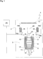
- a device 1 according to a first embodiment of the present invention is described.
- the device shown is a laser sintering or laser melting device 1.
- it contains a process chamber 3 with a chamber wall 4.
- a working plane 7 is defined by the upper opening of the container 5, the area of the working plane 7 lying within the opening, which can be used to build up the object 2, is referred to as construction field 8.
- a carrier 10 which is movable in a vertical direction V and to which a base plate 11 is attached which closes the container 5 at the bottom and thus forms its bottom.
- the base plate 11 can be a plate formed separately from the carrier 10 and attached to the carrier 10, or it can be formed integrally with the carrier 10.
- a construction platform 12 on which the object 2 is built can also be attached to the base plate 11.
- the object 2 can, however, also be built on the base plate 11 itself, which then serves as a construction platform.
- Fig. 1 the object 2 to be formed in the container 5 on the construction platform 12 below the working plane 7 is shown in an intermediate state with several solidified layers, surrounded by building material 13 that has remained unsolidified.
- the laser sintering device 1 further contains two storage containers 14a, 14b for a powdery building material 15 which can be solidified by electromagnetic radiation and a coater 16, which contains two coating units 16a, 16b movable in a horizontal direction H over the building field, for applying the building material 15 to the building field 8
- the radiant heater 17 is formed, for example, as an infrared heater.
- the laser sintering device 1 also contains an exposer 20 which can also be moved in the horizontal direction H over the construction field and which generates laser radiation 21 which is focused on the working plane 7.
- the imagesetter 20 includes a single exposure unit.
- This exposure unit 20 is designed as a line exposure unit which is capable of selectively exposing a line which extends transversely to its direction of movement and which extends over the entire area to be exposed.
- the laser sintering device 1 also contains a control unit 29, via which the individual components of the device 1 are controlled in a coordinated manner in order to carry out the construction process.
- the control unit can contain a CPU, the operation of which is controlled by a computer program (software).
- the computer program can be stored separately from the device on a storage medium from which it can be loaded into the device, in particular into the control unit 29.
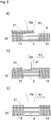
- Fig. 2a to f show steps of a method for producing a three-dimensional object by means of the device 1.
- the solidified part of the object 2 to be produced is surrounded by powder 13 that has remained unsolidified.
- the coating units 16a and 16b and the exposure unit 20 are arranged to the left of the construction field 8.
- the carrier 10 is first lowered by a height that corresponds to the desired layer thickness. Then as in Fig. 2a shown on the previously applied and selectively solidified powder layer 30 by means of a movement of the first coating unit 16a in a first coating direction R1 powdery build-up material 15 applied in the form of a first further powder layer 31.
- the application takes place at least over the entire cross section of the object 2 to be produced, preferably over the entire construction field 8, that is to say the area of the working plane 7, which can be lowered by a vertical movement of the carrier.
- the powder applied is preheated by the radiant heater 17.
- the imagesetter 20 then moves as in FIG Figure 2b shown in a first exposure direction, which is preferably the same as the first coating direction R1, over the construction field and selectively exposes the first further powder layer 31.
- the amount of energy introduced by the laser radiation 21 is set so that the cross-section of the object 2 to be produced A complete solidification of the powdery build-up material 15 takes place at corresponding points.
- the second coating unit 16b then performs as in FIG Figure 2b 1 shows an empty run in the first coating direction R1, ie it moves over the construction field 8 without applying construction material 15.
- the carrier 10 is lowered by a height that corresponds to the desired layer thickness.
- Fig. 2d shown on the previously applied and selectively solidified powder layer 31 by means of a movement of the second coating unit 16b in a second coating direction R2, which is the first coating direction R1 is opposite, powdery build-up material 15 is applied in the form of a second further powder layer 32.
- Opposite does not necessarily mean an angle of 180 ° in a plan view of the working plane, but only that the second coating direction R2 has a component which points in the opposite direction to the first coating direction R1.
- the angle between the first and the second coating direction is preferably between 15 and 210 degrees, more preferably it is 180 °.
- the application of the second further powder layer 32 takes place at least over the entire cross section of the object 2 to be manufactured, preferably over the entire construction field 8. During and after the application of the second further powder layer 32, the applied powder is preheated by the radiant heater 17.
- the imagesetter 20 then moves as in FIG Fig. 2e shown in a second exposure direction, which is preferably the same as the second coating direction R2, over the construction field and selectively exposes the second further powder layer 32.
- the amount of energy introduced by the laser radiation 21 is set so that the cross-section of the object 2 to be produced A complete solidification of the powdery build-up material 15 takes place at corresponding points.
- the first coating unit then performs as in Fig. 2f is shown an empty run in the first coating direction R1 over the construction field 8.
- the coating units 16a, 16b each require different height settings for the application of a powder layer or an empty run, they are height-adjustable, in particular their height is controllable, and mounted in the device 1.
- the device 1 of the present embodiment is characterized in that a coating unit 16a, 16b is arranged on each side of the imagesetter 20. This enables operation of the device as described above with reference to FIG Fig. 2a to f is described. With this operation, the production time for the object can be shortened considerably compared with the case in which only one coating unit is arranged on one side of the imagesetter, and thus the productivity of the apparatus can be increased.
- the coating travel and empty travel functions can also be interchanged.
- the coating unit 16a initially performs according to Fig. 2f (of the previous cycle) an empty run in the direction R2, then reverses and leads according to Fig. 2a (of the following cycle) a coating run in the direction of R1.
- the coating unit 16b also initially performs according to FIG Figure 2c an empty run in the direction R1 through, then reverses and leads according to Fig. 2d a coating run in the direction R2.
- one of the coating units or both can carry out a coating run before it is reversed and an empty run after it has reversed.
- the heating time that can be used for the heating process can be extended.
- one or both of the coating units can also carry out a coating run both before and after their reversal, during which a powder distribution layer is applied with a reduced thickness, the sum of the thicknesses of the two powder distribution layers yielding the desired total thickness of the powder layer.
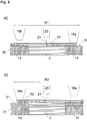
- Figures 3a and b show steps of an alternative method for producing a three-dimensional object by means of the device 1.
- This alternative method differs from that in FIG Fig. 2a to f
- the method shown is that the imagesetter 20 and the coating units 16a, 16b are moved together over the construction field instead of separately from one another. All other features of the method described above can also be transferred to the alternative method.
- Fig. 3a shows a method step in which the in Fig. 2a to c are combined with one another.
- the first coating unit 16a moves in the first coating direction R1 over the construction field 8 and applies the first further powder layer 31, which is then preheated by the radiant heater 17. While the first coating unit 16a is still moving over the construction field, at a distance behind it, the exposure device 21 also moves in the first coating direction R1 over the already completely applied area of the first further powder layer 31 and selectively solidifies it. At a distance behind the imagesetter, the second coating unit 16b runs an empty run in the first coating direction R1.
- Figure 3b shows a repetition of the in Fig. 3a shown in the reverse direction and represents a combination of the in Fig. 2d to f
- the second coating unit 16b applies the second further powder layer 32 in the second coating direction R2, which is then preheated by the radiant heater 17.
- the exposer 21 also travels in the second coating direction R2 over the already completely applied area of the second further powder layer 32 and selectively solidifies it.
- the first coating unit 16a runs an empty run in the second coating direction R2.
- this alternative method does not wait until a unit has driven over the construction field before the next unit begins its journey, a coating process and a consolidation process take place at the same time at different locations on the construction field. As a result, the production time for the object can be further shortened and productivity can be further increased.
- one of the coating units or both carry out a coating run before their reversal and an empty run after their reversal or carry out a coating run for a partial powder layer of reduced thickness both before and after their reversal.
- Figures 4a to d show various modifications of the in Fig. 1 device shown. These modifications differ from one another in the number and arrangement of the coating units and exposure units.
- Figure 4a shows schematically the in Fig. 1 Arrangement shown in a plan view.
- the exposure unit 20 contains a single exposure unit, while the application unit 16 contains two coating units 16a, 16b which are arranged in the coating direction R on both sides of the exposure unit, that is to say in front of and behind the exposure unit.
- the arrangement of the coating units is, so to speak, "mirrored" on the imagesetter.
- Figure 4b shows a reverse arrangement.
- the exposure unit is doubled here and on the Coater mirrored.
- the coater 16 thus contains a single coating unit in this case, while the exposure unit 20 contains two exposure units 20a, 20b, which are arranged in the coating direction R on both sides of the coater, that is, in front of and behind the coater.
- FIG. 1 The operation of a device with this arrangement is analogous to that in FIG Fig. 2 and 3 operation shown in Fig. 1 device shown.
- the preceding exposure unit performs an empty run
- the coating unit applies the new powder layer
- the respective subsequent exposure unit consolidates the newly applied powder layer.
- one of the exposure units or both can perform an exposure run before their reversal and an empty run after their reversal, or an exposure run with reduced energy both before and after their reversal, the total energy introduced in the two partial exposures being sufficient to solidify the building material.
- Figure 4c shows an arrangement in which both the coater 16 contains more than one coating unit and the imagesetter 20 contains more than one exposure unit.
- the coating units 16a-16e and the exposure units 20a-20d are arranged alternately in the coating direction, so that each coating unit (apart from the first and last arranged) is surrounded by two exposure units and each exposure unit by two coating units (apart from the first and last arranged).
- the total number of units is preferably uneven, so that the two units located first and last in the coating direction B are either both a coating unit or both are an exposure unit.
- the case is shown in which these two units are both a coating unit 16a, 16e, which is the preferred arrangement due to the higher cost of an exposure unit.
- the operation of a device with this arrangement is analogous to that in FIG Fig. 2 and 3 operation shown in Fig. 1 device shown.
- all coating and exposure devices are arranged to the left of construction field 8 in the figure.
- First the first coating unit 16a moves in the coating direction R over the construction field 8 and applies a powder layer, which is then preheated by the radiant heater 17 and solidified by the first exposure unit 20a.
- This is followed by the second coating unit 16b and the second exposure unit 20b and so on, until the last coating unit 16e has finished its empty journey over the construction field 8.
- the coating unit 16e which is now foremost, applies a layer of powder, which is solidified by the exposure unit 20d and so on, until the coating unit 16a, which is now at the rear, has completed its empty journey over the construction field 8.
- the individual units can be used as in Fig. 2 shown separately or as in Fig. 3 shown to be moved together over the construction site.
- the carrier 10 can be lowered by the desired layer thickness before each new powder layer is applied.
- the coating units 16a-16e and the exposure units 20a-20d are mounted in the device 1 in a height-adjustable manner, in particular their height can be controlled.
- each coating unit is then set higher by a predefined height, preferably by the height corresponding to a layer thickness of the construction material, than the preceding coating unit in the respective direction of movement.
- each exposure unit is set higher by a predefined height, preferably by the height corresponding to a layer thickness of the building material, than the exposure unit preceding in the respective direction of movement.
- a focal plane of the emitted radiation in each exposure unit can also be set higher than that of the preceding exposure unit in the respective direction of movement by a predefined height, preferably by the height corresponding to a layer thickness of the building material.
- both the coater and the exposer In a device in which successive layers are applied in different directions, between the application of the two layers, both the coater and the exposer must be braked to a standstill, the direction of the drive must be reversed and then back on again required work speed can be accelerated. This represents non-productive time that cannot be used for productive operation of the device.
- one of the coating units or both carry out a coating run before their reversal and an empty run after their reversal or carry out a coating run for a partial powder layer of reduced thickness both before and after their reversal.
- Figure 4d shows an arrangement similar to Figure 4c except that here two coating units 16b-16e are arranged between each exposure unit 20a-20c. Again, the preferred arrangement is shown in which the two front and last units in the coating direction B are both one coating unit 16a, 16f.
- each powder layer to be solidified consists of two powder distribution layers applied one behind the other, which are then exposed together and thus solidified. There the first powder distribution layer is heated by the radiant heater before the second powder distribution layer is applied. This in turn is heated by the radiant heater before the first and second powder distribution layers are exposed together and thereby selectively solidified.
- a powder layer to be solidified is applied in the form of two partial powder layers applied one behind the other (double coating) by moving two coating units over the construction field before the next exposure unit is moved over the construction field.
- double coating the coating unit located at the rear does not run an empty run, but applies the first powder distribution layer over the construction field during its first process and the second powder distribution layer in the opposite direction during its second process. This means that a double coating can already be carried out with the in Figure 4a The arrangement shown can be realized.
- each coating unit 16a-16f and the exposure units 20a-20c are height-adjustable, in particular their height can be controlled, mounted in the device 1, or the focal plane of the emitted radiation of the exposure units 20a-20c is adjustable.
- each coating unit is preferably set higher by the height corresponding to a layer thickness of a powder distribution layer than the preceding coating unit in the respective direction of movement, and each exposure unit (or its focal plane) is preferably one layer thickness one two powder distribution layers total powder layer formed is set higher than the preceding exposure unit in the respective direction of movement.
- the double coating has advantages above all when using old powder, which had already been used in the earlier manufacture of an object and remained as unconsolidated building material. From a certain proportion of old powder in the building material, the quality of the manufactured objects can decrease. With the separate heating of the individual powder layers in the double coating, a more homogeneous temperature division can be achieved, which leads to an improvement in the quality of the manufactured products or, while maintaining the same product quality, enables a higher proportion of old powder and thus more economical production.
- more coating units can also be arranged between an exposure unit, with the application of a powder layer to be solidified in the form of more than two powder distribution layers applied one behind the other.
- the present invention has been described with reference to a laser sintering or laser melting device, it is not limited to laser sintering or laser melting. It can be applied to any method for producing a three-dimensional object by applying layers and selectively solidifying a building material through the selective introduction of energy.
- the imagesetter can comprise, for example, one or more gas or solid-state lasers or any other type of laser such as laser diodes, in particular VCSEL (Vertical Cavity Surface Emitting Laser) or VECSEL (Vertical External Cavity Surface Emitting Laser).
- any device can be used as an exposure device with which energy can be applied selectively as wave or particle radiation to a layer of the building material.
- a laser it is possible, for example, to use another light source, an electron beam or any other energy or radiation source that is suitable for solidifying the building material.
- ⁇ ⁇ ⁇ ⁇ ⁇ ⁇ ⁇ ⁇ ⁇ ⁇ ⁇ ⁇ ⁇ ⁇ ⁇ ⁇ ⁇ ⁇ ⁇ ⁇ ⁇ ⁇ ⁇ ⁇ ⁇ ⁇ ⁇ ⁇ ⁇ ⁇ ⁇ ⁇ ⁇ ⁇ ⁇ ⁇ ⁇ ⁇ ⁇ ⁇ ⁇ ⁇ ⁇ ⁇ ⁇ ⁇ ⁇ ⁇ ⁇ ⁇ ⁇ ⁇ ⁇ ⁇ ⁇ ⁇ , ⁇ , ⁇ ⁇ ⁇ ⁇ ⁇ ⁇ ⁇ ⁇ ⁇ ⁇ ⁇ ⁇ ⁇ ⁇ ⁇ ⁇ ⁇ ⁇ ⁇ ⁇ ⁇ ⁇ ⁇ ⁇ ⁇ ⁇ ⁇ ⁇ ⁇ ⁇ ⁇ ⁇ ⁇ ⁇ ⁇ ⁇ ⁇ ⁇ ⁇ ⁇ ⁇ ⁇ ⁇ ⁇ ⁇ ⁇ ⁇ ⁇ ⁇ ⁇ ⁇ ⁇ ⁇ ⁇ ⁇ ⁇ ⁇ ⁇ ⁇ ⁇ ⁇ ⁇ ⁇ ⁇ ⁇ ⁇ ⁇ ⁇ ⁇
Description
Die vorliegende Erfindung bezieht sich auf eine Vorrichtung und ein Verfahren zum Herstellen eines dreidimensionalen Objekts durch schichtweises Aufbringen und selektives Verfestigen eines Aufbaumaterials.The present invention relates to a device and a method for producing a three-dimensional object by applying and selectively solidifying a building material in layers.
Vorrichtungen und Verfahren dieser Art werden beispielsweise beim Rapid Prototyping, Rapid Tooling oder Additive Manufacturing verwendet. Ein Beispiel eines solchen Verfahrens ist unter dem Namen "Selektives Lasersintern oder Laserschmelzen" bekannt. Dabei wird wiederholt eine dünne Schicht eines pulverförmigen Aufbaumaterials aufgebracht und das Aufbaumaterial in jeder Schicht durch selektives Bestrahlen mit einem Laserstrahl selektiv verfestigt.Devices and methods of this type are used, for example, in rapid prototyping, rapid tooling or additive manufacturing. An example of such a process is known as "selective laser sintering or laser melting". A thin layer of a powdery building material is repeatedly applied and the building material is selectively solidified in each layer by selective irradiation with a laser beam.
In der zum Anmeldetag der vorliegenden Erfindung noch nicht veröffentlichten Patentanmeldung
Die
Die
Die Aufgabe der vorliegenden Erfindung besteht darin, eine alternative bzw. verbesserte Vorrichtung bzw. ein alternatives bzw. verbessertes Verfahren zum Herstellen eines dreidimensionalen Objekts durch schichtweises Aufbringen und selektives Verfestigen eines pulverförmigen Aufbaumaterials bereitzustellen.The object of the present invention is to provide an alternative or improved device or an alternative or improved method for producing a three-dimensional object by applying and selectively solidifying a powdery building material in layers.
Die Aufgabe wird gelöst durch eine Vorrichtung gemäß Anspruch 1 oder ein Verfahren gemäß Anspruch 9. Weiterbildungen der Erfindung sind jeweils in den Unteransprüchen angegeben. Dabei kann das Verfahren auch durch die untenstehenden bzw. in den Unteransprüchen ausgeführten Merkmale der Vorrichtung weitergebildet sein oder jeweils umgekehrt.The object is achieved by a device according to claim 1 or a method according to claim 9. Further developments of the invention are specified in the subclaims. The method can also be developed further by the features of the device below or in the subclaims, or vice versa.
Die erfindungsgemäße Vorrichtung dient zum Herstellen eines dreidimensionalen Objekts durch schichtweises Aufbringen und selektives Verfestigen eines Aufbaumaterials. Sie enthält einen in einer Beschichtungsrichtung über ein Baufeld bewegbaren Beschichter mit zumindest einer ersten Beschichtungseinheit zum Aufbringen einer Schicht des Aufbaumaterials auf das Baufeld und ein in der Beschichtungsrichtung über das Baufeld bewegbarer Belichter mit zumindest einer ersten Belichtungseinheit, die zum Aussenden einer zum Verfestigen des Aufbaumaterials geeigneten Strahlung geeignet ist, zum selektiven Verfestigen der aufgebrachten Schicht des Aufbaumaterials an Stellen, die einem Querschnitt des herzustellenden Objekts entsprechen. Die Vorrichtung ist ausgebildet und/oder gesteuert, die Schritte des Aufbringens und des selektiven Verfestigens zu wiederholen, bis das Objekt fertiggestellt ist. Der Beschichter enthält zumindest eine zweite Beschichtungseinheit, die in der Beschichtungsrichtung auf der anderen Seite der ersten Belichtungseinheit angeordnet ist als die erste Beschichtungseinheit. Zusätzlich oder alternativ enthält der Belichter zumindest eine zweite Belichtungseinheit, die in der Beschichtungsrichtung auf der anderen Seite der ersten Beschichtungseinheit angeordnet ist als die erste Belichtungseinheit. Mit einer solchen Vorrichtung kann beispielsweise die Herstellungszeit für das Objekt verglichen mit dem Fall, in dem nur eine Beschichtungseinheit auf einer Seite des Belichters angeordnet ist, erheblich verkürzt und somit die Produktivität gesteigert werden. Die Beschichtungseinheit(en) und Belichtungseinheit(en) können im Rahmen der Erfindung nämlich so miteinander in ihrer Bewegung koordiniert werden, dass Leerzeiten weitest gehend vermieden werden können.The device according to the invention serves to produce a three-dimensional object by applying and selectively solidifying a building material in layers. It contains a coater that can be moved in a coating direction over a construction field with at least one first coating unit for applying a layer of the building material to the construction field and an exposure unit that can be moved in the coating direction over the construction field with at least one first exposure unit, which is suitable for sending out one for solidifying the building material Radiation is suitable for the selective solidification of the applied layer of the building material at locations that correspond to a cross section of the object to be manufactured. The device is designed and / or controlled to repeat the steps of application and selective solidification until the object is completed. The coater contains at least one second coating unit which is arranged in the coating direction on the other side of the first exposure unit than the first coating unit. Additionally or alternatively, the exposure unit contains at least one second exposure unit, which is arranged in the coating direction on the other side of the first coating unit than the first exposure unit. With such a device, for example, the production time for the object compared with the case in which only one coating unit is arranged on one side of the imagesetter, can be shortened considerably and thus the productivity can be increased. The movement of the coating unit (s) and exposure unit (s) can in fact be coordinated with one another within the scope of the invention in such a way that idle times can be largely avoided.
Zudem sind die erste Belichtungseinheit und eventuelle weitere Belichtungseinheiten als Zeilenbelichter, insbesondere als VCSEL-basierte bzw. als VECSEL-basierte Zeilenbelichter ausgebildet. Dadurch kann beispielsweise ein besonders effizientes Verfestigen des Aufbaumaterials mittels Strahlung durchgeführt werden. Insbesondere wird in diesem Zusammenhang auf die Offenbarung der eingangs genannten
Vorzugsweise enthält die Vorrichtung zwei oder mehr Beschichtungseinheiten und zwei oder mehr Belichtungseinheiten, wobei die Beschichtungseinheiten und die Belichtungseinheiten in der Beschichtungsrichtung abwechselnd angeordnet sind, wobei vorzugsweise die beiden in der Beschichtungsrichtung zuvorderst und zuletzt liegenden Einheiten entweder beide eine Beschichtungseinheit oder beide eine Belichtungseinheit sind. Dadurch kann beispielsweise die Herstellungszeit für das Objekt weiter verkürzt und somit die Produktivität weiter gesteigert werden. Besonders bevorzugt (siehe auch die Ausführungen zur bevorzugten Anzahl der Beschichtungseinheiten im Vergleich zu der der Belichtungseinheiten) ist es, dass die beiden in der Beschichtungsrichtung zuvorderst und zuletzt liegenden Einheiten jeweils Beschichtungseinheiten sind.The device preferably contains two or more coating units and two or more exposure units, the coating units and the exposure units being arranged alternately in the coating direction, with preferably the two units lying first and last in the coating direction either both being a coating unit or both being an exposure unit. As a result, for example, the production time for the object can be further shortened and thus productivity can be further increased. It is particularly preferred (see also the statements on the preferred number of coating units in comparison to that of the exposure units) that the two units which are first and last in the coating direction are each coating units.
Vorzugsweise enthält die Vorrichtung zwei oder mehr Beschichtungseinheiten und zwei oder mehr Belichtungseinheiten, wobei zwischen zwei Belichtungseinheiten zumindest eine Beschichtungseinheit angeordnet ist, wobei vorzugsweise die beiden in der Beschichtungsrichtung zuvorderst und zuletzt liegenden Einheiten jeweils eine Beschichtungseinheit sind. Dadurch kann beispielsweise die Herstellungszeit für das Objekt auch bei einer Doppelbeschichtung verkürzt und somit die Produktivität gesteigert werden.The device preferably contains two or more coating units and two or more exposure units, with at least one coating unit being arranged between two exposure units, the two foremost and last units in the coating direction each being a coating unit. In this way, for example, the production time for the object can be shortened even with a double coating and thus productivity can be increased.
Es ist weiterhin bevorzugt, dass die Anzahl der Beschichtungseinheiten größer ist, besonders bevorzugt um die Zahl 1 größer ist, als die Anzahl der Belichtungseinheiten. Damit übersteigt also die Anzahl an Beschichtungseinheiten die der Belichtungseinheiten, was insbesondere finanzielle Einsparungseffekte mit sich bringt: Belichtungseinheiten sind derzeit in der Regel teurer in der Beschaffung, da komplizierter in ihren Funktionen, als Beschichtungseinheiten. Hinzu kommt, dass auch der Gesamtbetrieb durch diese Maßnahme vereinfacht werden kann: Jede Belichtungseinheit muss in der Regel aktiv betrieben werden, d.h. insbesondere angesteuert werden können. Dies bedeutet, dass jeder Belichtungseinheit Signalverbindungen zugeordnet sind. Dagegen ist eine aktive Steuerung von Beschichtungseinheiten in deren Betrieb nicht zwangsläufig nötig, so dass durch eine höhere Anzahl von Beschichtungseinheiten als Belichtungseinheiten auch prozesstechnisch eine Vereinfachung realisierbar ist.It is further preferred that the number of coating units is greater, particularly preferably one greater than the number of exposure units. The number of coating units thus exceeds that of the exposure units, which in particular has financial savings effects: Exposure units are currently usually more expensive to purchase because their functions are more complicated than coating units. In addition, the overall operation can be simplified by this measure: Each exposure unit must generally be operated actively, i.e. in particular it must be able to be controlled. This means that signal connections are assigned to each exposure unit. In contrast, an active control of coating units is not absolutely necessary in their operation, so that a simplification can also be achieved in terms of process technology by a higher number of coating units than exposure units.
Vorzugsweise ist der Beschichter und/oder der Belichter dazu ausgebildet, sowohl bei einer Bewegung in der Beschichtungsrichtung als auch bei einer Bewegung in einer der Beschichtungsrichtung entgegengesetzten Richtung eine Schicht des Aufbaumaterials auf das Baufeld aufzubringen bzw. die aufgebrachte Schicht des Aufbaumaterials zu verfestigen. Dadurch kann beispielsweise ein Betrieb der Vorrichtung in zwei Richtungen, nämlich der Beschichtungsrichtung und ihrer entgegengesetzten Richtung erfolgen.The coater and / or the exposer is preferably designed for this purpose, both during a movement in the coating direction as well as to apply a layer of the building material to the building field or to solidify the applied layer of building material when moving in a direction opposite to the coating direction. In this way, for example, the device can be operated in two directions, namely the coating direction and its opposite direction.
Vorzugsweise sind die erste Beschichtungseinheit und/oder eventuelle weitere Beschichtungseinheiten sowie die erste Belichtungseinheit und/oder eventuelle weitere Belichtungseinheiten höhenverstellbar, insbesondere in ihrer Höhe steuerbar, in der Vorrichtung angebracht. Dadurch können beispielsweise während des Betriebs alle eben genannten Einheiten jeweils auf eine für den momentanen Betrieb der Vorrichtung geeignete Höhe eingestellt bzw. gesteuert werden.The first coating unit and / or any further coating units and the first exposure unit and / or any further exposure units are preferably mounted in the device in a height-adjustable manner, in particular their height can be controlled. In this way, for example, all the units just mentioned can each be set or controlled to a height suitable for the current operation of the device.
Vorzugsweise enthält die Vorrichtung weiter einen höhenverstellbaren Träger, der zum Halten der aufgebrachten Pulverschichten bestimmt ist. Dadurch kann beispielsweise die Schichtdicke der aufgebrachten Pulverschicht durch Absenken des Trägers eingestellt werden.The device preferably further contains a height-adjustable support which is intended to hold the powder layers applied. In this way, for example, the layer thickness of the applied powder layer can be adjusted by lowering the carrier.
Vorzugsweise enthält die Vorrichtung weiter eine Strahlungsheizung zum Erwärmen der aufgebrachten Pulverschicht vor ihrer Verfestigung. Dadurch kann beispielsweise die aufgebrachte Pulverschicht vor ihrer Verfestigung vorgeheizt werden.The device preferably further contains a radiant heater for heating the applied powder layer before it solidifies. In this way, for example, the applied powder layer can be preheated before it solidifies.
Das erfindungsgemäße Verfahren dient zum Herstellen eines dreidimensionalen Objekts durch schichtweises Aufbringen und selektives Verfestigen eines Aufbaumaterials. Es enthält die folgenden Schritte: Aufbringen einer Schicht des Aufbaumaterials mittels eines in einer Beschichtungsrichtung über ein Baufeld fahrenden Beschichters mit zumindest einer ersten Beschichtungseinheit, selektives Verfestigen der aufgebrachten Schicht des Aufbaumaterials an Stellen, die einem Querschnitt des herzustellenden Objekts entsprechen, mittels eines über das Baufeld fahrenden Belichters mit zumindest einer ersten Belichtungseinheit und Wiederholen der Schritte des Aufbringens und des selektiven Verfestigens, bis das Objekt fertiggestellt ist. Dabei enthält der Beschichter zumindest eine zweite Beschichtungseinheit, die in der Beschichtungsrichtung auf der anderen Seite der ersten Belichtungseinheit angeordnet ist als die erste Beschichtungseinheit. Zusätzlich oder alternativ enthält der Belichter zumindest eine zweite Belichtungseinheit, die in der Beschichtungsrichtung auf der anderen Seite der ersten Beschichtungseinheit angeordnet ist als die erste Belichtungseinheit. Mit einem solchen Verfahren kann beispielsweise die Herstellungszeit für das Objekt verglichen mit dem Fall, in dem nur eine Beschichtungseinheit auf einer Seite des Belichters angeordnet ist, erheblich verkürzt und somit die Produktivität gesteigert werden.The method according to the invention is used to produce a three-dimensional object by applying and selectively solidifying a building material in layers. It includes the following Steps: applying a layer of the building material by means of a coater moving in one coating direction over a construction field with at least one first coating unit, selective solidification of the applied layer of the building material at locations that correspond to a cross section of the object to be produced by means of an exposure device moving over the construction field with at least a first exposure unit and repeating the steps of applying and selectively solidifying until the object is completed. The coater contains at least one second coating unit, which is arranged in the coating direction on the other side of the first exposure unit than the first coating unit. Additionally or alternatively, the exposure unit contains at least one second exposure unit, which is arranged in the coating direction on the other side of the first coating unit than the first exposure unit. With such a method, for example, the production time for the object can be shortened considerably compared with the case in which only one coating unit is arranged on one side of the imagesetter, and thus productivity can be increased.
Zudem sind die erste Belichtungseinheit und eventuelle weitere Belichtungseinheiten als Zeilenbelichter, insbesondere als VCSEL-basierte bzw. als VECSEL-basierte Zeilenbelichter ausgebildet.In addition, the first exposure unit and any further exposure units are designed as line exposure units, in particular as VCSEL-based or VECSEL-based line exposure units.
Vorzugsweise werden jede Beschichtungseinheit und jede Belichtungseinheit einmal in einer ersten Richtung über das Baufeld bewegt und anschließend jede Beschichtungseinheit und jede Belichtungseinheit in umgekehrter Reihenfolge einmal in einer der ersten Richtung entgegengesetzten Richtung über das Baufeld bewegt. Dadurch kann beispielsweise ein Betrieb der Vorrichtung in zwei Richtungen (also in der Beschichtungsrichtung und deren entgegengesetzten Richtung) erfolgen.Preferably, each coating unit and each exposure unit are moved once in a first direction over the construction field and then each coating unit and each exposure unit in the reverse order once in one of the first direction moves across the construction field in the opposite direction. In this way, for example, the device can be operated in two directions (that is, in the coating direction and its opposite direction).
Vorzugsweise wird jede Beschichtungseinheit und/oder jede Belichtungseinheit um eine vordefinierte Höhe, vorzugsweise um die einer Schichtdicke des Aufbaumaterials entsprechende Höhe, höher eingestellt als die in der jeweiligen Bewegungsrichtung vorausgehende Beschichtungseinheit. In diesem Zusammenhang ist es besonders bevorzugt, dass mindestens ein Teil (vorzugsweise alle) der (insbesondere) Beschichtungseinheiten bzw. Belichtungseinheiten wie oben erwähnt höhenverstellbar in der Vorrichtung angebracht ist. Dadurch kann beispielsweise ein Aufbringen und Verfestigen von mehreren Schichten während eines Durchgangs, d.h. im Verlaufe einer Bewegung aller Beschichtungseinheiten und Verfestigungseinheiten in einer Bewegungsrichtung bzw. in der Bewegungsrichtung und der ihr entgegengesetzten Bewegungsrichtung, erfolgen.Each coating unit and / or each exposure unit is preferably set higher by a predefined height, preferably by the height corresponding to a layer thickness of the building material, than the preceding coating unit in the respective direction of movement. In this context, it is particularly preferred that at least some (preferably all) of the (in particular) coating units or exposure units, as mentioned above, are mounted in the device in a height-adjustable manner. In this way, for example, several layers can be applied and solidified during one pass, i.e. in the course of a movement of all coating units and solidification units in one direction of movement or in the direction of movement and the direction of movement opposite to it.
Vorzugsweise werden zumindest eine Beschichtungseinheit und zumindest eine Belichtungseinheit so über das Baufeld bewegt, dass zeitgleich an verschiedenen Orten des Baufelds ein Beschichtungsvorgang und ein Verfestigungsvorgang stattfinden. Dadurch kann beispielsweise die Herstellungszeit für das Objekt weiter verkürzt und somit die Produktivität weiter gesteigert werden.At least one coating unit and at least one exposure unit are preferably moved over the construction field in such a way that a coating process and a solidification process take place at the same time at different locations on the construction field. As a result, for example, the production time for the object can be further shortened and thus productivity can be further increased.
Vorzugsweise ist jede Belichtungseinheit eine Belichtungseinheit, die eine Strahlung aussendet, die zum Verfestigen des Aufbaumaterials geeignet ist, und eine Fokusebene der ausgesendeten Strahlung ist bei jeder Belichtungseinheit um eine vordefinierte Höhe, vorzugsweise um die einer Schichtdicke des Aufbaumaterials entsprechende Höhe, höher eingestellt als diejenige der in der jeweiligen Bewegungsrichtung vorausgehenden Belichtungseinheit. Dadurch kann beispielsweise das Verfestigen des Aufbaumaterials mittels Strahlung durchgeführt werden, und das Einstellen der Fokusebene kann ein höhenverstellbares Anbringen der Belichtungseinheiten überflüssig machen bzw. ergänzen.Preferably, each exposure unit is an exposure unit that emits radiation that is suitable for solidifying the building material, and a focal plane of the emitted radiation is set higher than that of the each exposure unit by a predefined height, preferably by the height corresponding to a layer thickness of the building material preceding exposure unit in the respective direction of movement. In this way, for example, the build-up material can be solidified by means of radiation, and the setting of the focal plane can make a height-adjustable attachment of the exposure units superfluous or supplement it.
Weitere Merkmale und Zweckmäßigkeiten der Erfindung ergeben sich aus der Beschreibung von Ausführungsbeispielen anhand der beigefügten Zeichnungen.
- Fig. 1
- ist eine schematische, teilweise im Schnitt dargestellte Ansicht einer Vorrichtung zum schichtweisen Herstellen eines dreidimensionalen Objekts gemäß einer ersten Ausführungsform der vorliegenden Erfindung.
- Fig. 2a bis f
- sind schematische Darstellungen eines Ablaufs eines Ausführungsbeispiels eines erfindungsgemäßen Verfahrens zum schichtweisen Herstellen eines dreidimensionalen Objekts mit der in
Fig. 1 gezeigten Vorrichtung. - Fig. 3a und b
- sind schematische Darstellungen eines Ablaufs eines alternativen Ausführungsbeispiels eines erfindungsgemäßen Verfahrens zum schichtweisen Herstellen eines dreidimensionalen Objekts mit der in
Fig. 1 gezeigten Vorrichtung. - Fig. 4a bis d
- sind schematische Draufsichten auf verschiedene Abwandlungen der Anordnungen von Beschichtungseinheiten und Belichtungseinheiten.
- Fig. 1
- Figure 3 is a schematic, partially sectioned view of an apparatus for layering Manufacture of a three-dimensional object according to a first embodiment of the present invention.
- Fig. 2a to f
- are schematic representations of a sequence of an embodiment of a method according to the invention for the layer-by-layer production of a three-dimensional object with the in
Fig. 1 device shown. - Figures 3a and b
- are schematic representations of a sequence of an alternative embodiment of a method according to the invention for the layer-by-layer production of a three-dimensional object with the in
Fig. 1 device shown. - Figures 4a to d
- are schematic plan views of various modifications of the arrangements of coating units and exposure units.
Im Folgenden wird mit Bezug auf
In der Prozesskammer 3 ist ein nach oben offener Behälter 5 mit einer Behälterwandung 6 angeordnet. Durch die obere Öffnung des Behälters 5 ist eine Arbeitsebene 7 definiert, wobei der innerhalb der Öffnung liegende Bereich der Arbeitsebene 7, der zum 0 Aufbau des Objekts 2 verwendet werden kann, als Baufeld 8 bezeichnet wird.A
In dem Behälter 5 ist ein in einer vertikalen Richtung V bewegbarer Träger 10 angeordnet, an dem eine Grundplatte 11 angebracht ist, die den Behälter 5 nach unten abschließt und damit dessen Boden bildet. Die Grundplatte 11 kann eine getrennt von dem Träger 10 gebildete Platte sein, die an dem Träger 10 befestigt ist, oder sie kann integral mit dem Träger 10 gebildet sein. Je nach verwendetem Pulver und Prozess kann auf der Grundplatte 11 noch eine Bauplattform 12 angebracht sein, auf der das Objekt 2 aufgebaut wird. Das Objekt 2 kann aber auch auf der Grundplatte 11 selber aufgebaut werden, die dann als Bauplattform dient. In
Die Lasersintervorrichtung 1 enthält weiter zwei Vorratsbehälter 14a, 14b für ein durch elektromagnetische Strahlung verfestigbares pulverförmiges Aufbaumaterial 15 und einen Beschichter 16, der zwei in einer horizontalen Richtung H über das Baufeld bewegbare Beschichtungseinheiten 16a, 16b enthält, zum Aufbringen des Aufbaumaterials 15 auf das Baufeld 8. In der Prozesskammer ist ferner eine Strahlungsheizung 17 angeordnet, die zum Beheizen des auf das Baufeld 8 aufgebrachten Aufbaumaterials 15 dient. Die Strahlungsheizung 17 ist beispielsweise als Infrarotstrahler gebildet.The laser sintering device 1 further contains two
Die Lasersintervorrichtung 1 enthält ferner einen ebenfalls in der horizontalen Richtung H über das Baufeld bewegbaren Belichter 20, der eine Laserstrahlung 21 erzeugt, die auf die Arbeitsebene 7 fokussiert wird. Gemäß der vorliegenden Ausführungsform enthält der Belichter 20 eine einzige Belichtungseinheit. Diese Belichtungseinheit 20 ist als Zeilenbelichter ausgebildet, der in der Lage ist, selektiv eine sich quer zu seiner Bewegungsrichtung erstreckende Linie zu belichten, die sich über den gesamten zu belichtenden Bereich erstreckt.The laser sintering device 1 also contains an
Weiter enthält die Lasersintervorrichtung 1 eine Steuereinheit 29, über die die einzelnen Bestandteile der Vorrichtung 1 in koordinierter Weise zum Durchführen des Bauprozesses gesteuert werden. Die Steuereinheit kann eine CPU enthalten, deren Betrieb durch ein Computerprogramm (Software) gesteuert wird. Das Computerprogramm kann getrennt von der Vorrichtung auf einem Speichermedium gespeichert sein, von dem aus es in die Vorrichtung, insbesondere in die Steuereinheit 29 geladen werden kann.
In einem durch vorangegangene Prozessschritte aufgebauten Pulverbett 30 ist der verfestigte Teil des herzustellenden Objekts 2 von unverfestigt gebliebenem Pulver 13 umgeben. Vor dem in
Zum weiteren schichtweisen Aufbauen des Objekts 2 wird zunächst der Träger 10 um eine Höhe abgesenkt, die der gewünschten Schichtdicke entspricht. Dann wird wie in
Anschließend fährt der Belichter 20 wie in
Anschließend führt die zweite Beschichtungseinheit 16b wie in
Danach werden die oben beschriebenen Schritte in umgekehrter Richtung wiederholt.Then the steps described above are repeated in reverse.
Zunächst wird der Träger 10 um eine Höhe abgesenkt, die der gewünschten Schichtdicke entspricht. Dann wird wie in
Dabei bedeutet entgegengesetzt nicht unbedingt einen Winkel von 180° in einer Draufsicht auf die Arbeitsebene, sondern nur, dass die zweite Beschichtungsrichtung R2 eine Komponente hat, die in die Gegenrichtung der ersten Beschichtungsrichtung R1 zeigt. Vorzugsweise liegt der Winkel zwischen der ersten und der zweiten Beschichtungsrichtung zwischen 15 und 210 Grad, in weiter bevorzugter Weise beträgt er 180°.Opposite does not necessarily mean an angle of 180 ° in a plan view of the working plane, but only that the second coating direction R2 has a component which points in the opposite direction to the first coating direction R1. The angle between the first and the second coating direction is preferably between 15 and 210 degrees, more preferably it is 180 °.
Auch das Aufbringen der zweiten weiteren Pulverschicht 32 erfolgt zumindest über den gesamten Querschnitt des herzustellenden Objekts 2, vorzugsweise über das gesamte Baufeld 8. Während und nach dem Aufbringen der zweiten weiteren Pulverschicht 32 wird das aufgebrachte Pulver durch die Strahlungsheizung 17 vorgeheizt.The application of the second
Anschließend fährt der Belichter 20 wie in
Anschließend führt die erste Beschichtungseinheit wie in
Damit ist der Ausgangszustand wieder erreicht, und die in
Da die Beschichtungseinheiten 16a, 16b jeweils für das Auftragen einer Pulverschicht bzw. eine Leerfahrt unterschiedliche Höheneinstellungen benötigen, sind sie höhenverstellbar, insbesondere in ihrer Höhe steuerbar, in der Vorrichtung 1 angebracht.Since the
Gegenüber dem bekannten Stand der Technik ist die Vorrichtung 1 der vorliegenden Ausführungsform dadurch gekennzeichnet, dass auf beiden Seiten des Belichters 20 je eine Beschichtungseinheit 16a, 16b angeordnet ist. Dadurch wird ein Betrieb der Vorrichtung ermöglicht, wie er oben mit Bezug auf
In einer Abwandlung des oben beschriebenen Verfahrens können auch die Funktionen Beschichtungsfahrt und Leerfahrt vertauscht sein. Nach dem oben beschriebenen Ablauf führt die Beschichtungseinheit 16a zunächst gemäß
In einer weiteren Abwandlung kann auch eine der Beschichtungseinheiten oder beide sowohl vor als auch nach ihrer Umkehr eine Beschichtungsfahrt durchführen, bei der jeweils eine Pulverteilschicht mit einer verringerten Dicke aufgetragen wird, wobei durch die Summe der Dicken der beiden Pulverteilschicht die gewünschte Gesamtdicke der Pulverschicht ergibt. Bei einer solchen Doppelbeschichtung (Aufbringen einer zu verfestigenden Pulverschicht in Form von zwei hintereinander aufgebrachten Pulverteilschichten) ergeben sich, wie weiter unten mit Bezug auf 4d beschrieben, vor allem bei der Verwendung von Altpulver Vorteile wie z.B. eine Qualitätsverbesserung der hergestellten Produkte.In a further modification, one or both of the coating units can also carry out a coating run both before and after their reversal, during which a powder distribution layer is applied with a reduced thickness, the sum of the thicknesses of the two powder distribution layers yielding the desired total thickness of the powder layer. With such a double coating (application of a powder layer to be solidified in the form of two powder distribution layers applied one behind the other), as described further below with reference to FIG. 4d, advantages such as an improvement in the quality of the manufactured products result, especially when using old powder.
Damit ist der Ausgangszustand wieder erreicht, und die in
Weil bei diesem alternativen Verfahren nicht gewartet wird, bis eine Einheit über das Baufeld gefahren ist, bevor die nächste Einheit ihre Fahrt beginnt, finden zeitgleich an verschiedenen Orten des Baufelds ein Beschichtungsvorgang und ein Verfestigungsvorgang statt. Dadurch kann die Herstellungszeit für das Objekt weiter verkürzt und die Produktivität weiter gesteigert werden.Because this alternative method does not wait until a unit has driven over the construction field before the next unit begins its journey, a coating process and a consolidation process take place at the same time at different locations on the construction field. As a result, the production time for the object can be further shortened and productivity can be further increased.
Auch hier kann wie bei der Abwandlung des mit Bezug auf
Der Betrieb einer Vorrichtung mit dieser Anordnung verläuft analog zu dem in
Ähnlich wie bei der Abwandlung der mit Bezug auf
Auch mit dieser Anordnung kann also die Herstellungszeit für das Objekt verkürzt und die Produktivität gesteigert werden. Aufgrund der höheren Kosten einer Belichtungseinheit gegenüber einer Beschichtungseinheit wird jedoch vorzugsweise wie in
Der Betrieb einer Vorrichtung mit dieser Anordnung verläuft analog zu dem in
Auch hierbei können die einzelnen Einheiten wie in
In ähnlicher Weise ist jede Belichtungseinheit um eine vordefinierte Höhe, vorzugsweise um die einer Schichtdicke des Aufbaumaterials entsprechende Höhe, höher eingestellt als die in der jeweiligen Bewegungsrichtung vorausgehende Belichtungseinheit. Alternativ oder ergänzend zu einer Höhenverstellung der Belichtungseinheit kann bei ihnen auch eine Fokusebene der ausgesendeten Strahlung bei jeder Belichtungseinheit um eine vordefinierte Höhe, vorzugsweise um die einer Schichtdicke des Aufbaumaterials entsprechende Höhe, höher eingestellt sein als diejenige der in der jeweiligen Bewegungsrichtung vorausgehenden Belichtungseinheit.In a similar way, each exposure unit is set higher by a predefined height, preferably by the height corresponding to a layer thickness of the building material, than the exposure unit preceding in the respective direction of movement. As an alternative or in addition to adjusting the height of the exposure unit, a focal plane of the emitted radiation in each exposure unit can also be set higher than that of the preceding exposure unit in the respective direction of movement by a predefined height, preferably by the height corresponding to a layer thickness of the building material.
Bei einer Vorrichtung, bei der aufeinanderfolgende Schichten in unterschiedlicher Richtung aufgetragen werden, muss zwischen dem Aufbringen der beiden Schichten sowohl der Beschichter als auch der Belichter in den Stillstand abgebremst werden, die Richtung des Antriebs umgekehrt werden und dann wieder auf die erforderliche Arbeitsgeschwindigkeit beschleunigt werden. Das stelle eine Nebenzeit dar, die nicht zum produktiven Betrieb der Vorrichtung genutzt werden kann.In a device in which successive layers are applied in different directions, between the application of the two layers, both the coater and the exposer must be braked to a standstill, the direction of the drive must be reversed and then back on again required work speed can be accelerated. This represents non-productive time that cannot be used for productive operation of the device.
Durch die abwechselnde Anordnung mehrerer Beschichtungs- und Belichtungseinheiten hintereinander können mehrere Schichten aufgebracht und verfestigt werden, bevor ein solcher Umkehrvorgang erforderlich ist. Dadurch fällt die für das Umkehren erforderliche Zeit weniger ins Gewicht, als wenn es nach jedem Aufbringen und Verfestigen einer Schicht erforderlich ist. Dadurch kann die Herstellungszeit für das Objekt weiter verkürzt und die Produktivität weiter gesteigert werden.Due to the alternating arrangement of several coating and exposure units one behind the other, several layers can be applied and solidified before such a reversal process is necessary. As a result, the time required for reversing is less of a concern than if it is required after each application and solidification of a layer. As a result, the production time for the object can be further shortened and productivity can be further increased.
Auch hier kann wie bei der Abwandlung des mit Bezug auf
Der Betrieb einer Vorrichtung mit dieser Anordnung verläuft analog zu dem Betrieb der in
Das Aufbringen einer zu verfestigenden Pulverschicht in Form von zwei hintereinander aufgebrachten Pulverteilschichten (Doppelbeschichtung) geschieht dadurch, dass jeweils zwei Beschichtungseinheiten über das Baufeld verfahren, bevor die nächste Belichtungseinheit über das Baufeld verfahren wird. Die jeweils hinten liegende Beschichtungseinheit führt bei dieser Anordnung keine Leerfahrt durch, sondern bringt bei ihrem ersten Verfahren über das Baufeld die erste Pulverteilschicht auf und bei ihrem zweiten Verfahren in der entgegengesetzten Richtung die zweite Pulverteilschicht. Somit kann eine Doppelbeschichtung auch bereits mit der in
Auch hierbei können die einzelnen Einheiten wie in
Die Doppelbeschichtung hat vor allem Vorteile bei der Verwendung von Altpulver, das bereits beim früheren Herstellen eines Objekts verwendet worden war und als unverfestigtes Aufbaumaterial übrig geblieben ist. Ab einem bestimmten Anteil von Altpulver an dem Aufbaumaterial kann die Qualität der hergestellten Objekte sinken. Durch das getrennte Beheizen der einzelnen Pulverteilschichten bei der Doppelbeschichtung kann eine homogenere Temperaturteilung erzielt werden, was zu einer Qualitätsverbesserung der hergestellten Produkte führt bzw. bei gleichbleibender Produktqualität einen höheren Anteil von Altpulver und damit eine wirtschaftlichere Produktion ermöglicht.The double coating has advantages above all when using old powder, which had already been used in the earlier manufacture of an object and remained as unconsolidated building material. From a certain proportion of old powder in the building material, the quality of the manufactured objects can decrease. With the separate heating of the individual powder layers in the double coating, a more homogeneous temperature division can be achieved, which leads to an improvement in the quality of the manufactured products or, while maintaining the same product quality, enables a higher proportion of old powder and thus more economical production.
Durch die in
Anstelle von zwei können auch mehr Beschichtungseinheiten zwischen einer Belichtungseinheit angeordnet sein, wobei das Aufbringen einer zu verfestigende Pulverschicht in Form von mehr als zwei hintereinander aufgebrachten Pulverteilschichten geschieht.Instead of two, more coating units can also be arranged between an exposure unit, with the application of a powder layer to be solidified in the form of more than two powder distribution layers applied one behind the other.
Merkmale dieser Anordnungen können, soweit möglich, beliebig miteinander kombiniert werden. So ist z.B. eine Anordnung möglich, in der zwischen zwei Belichtungseinheiten teilweise nur eine Beschichtungseinheit angeordnet ist und teilweise zwei oder mehr.Features of these arrangements can, as far as possible, be combined with one another as desired. For example, an arrangement is possible in which, in some cases, only one coating unit is arranged between two exposure units and in some cases two or more.
Auch wenn die vorliegende Erfindung anhand einer Lasersinter- bzw. Laserschmelzvorrichtung beschrieben wurde, ist sie nicht auf das Lasersintern oder Laserschmelzen eingeschränkt. Sie kann auf beliebige Verfahren zum Herstellen eines dreidimensionalen Objektes durch schichtweises Aufbringen und selektives Verfestigen eines Aufbaumaterials durch selektives Einbringen von Energie angewendet werden.Even if the present invention has been described with reference to a laser sintering or laser melting device, it is not limited to laser sintering or laser melting. It can be applied to any method for producing a three-dimensional object by applying layers and selectively solidifying a building material through the selective introduction of energy.
Der Belichter kann beispielsweise einen oder mehrere Gas- oder Festkörperlaser oder jede andere Art von Laser wie z.B. Laserdioden, insbesondere VCSEL (Vertical Cavity Surface Emitting Laser) oder VECSEL (Vertical External Cavity Surface Emitting Laser) umfassen. Allgemein kann als Belichter jede Einrichtung verwendet werden, mit der Energie als Wellen- oder Teilchenstrahlung selektiv auf eine Schicht des Aufbaumaterials aufgebracht werden kann. Anstelle eines Lasers können beispielsweise eine andere Lichtquelle, ein Elektronenstrahl oder jede andere Energie- bzw. Strahlenquelle verwendet werden, die geeignet ist, das Aufbaumaterial zu verfestigen.The imagesetter can comprise, for example, one or more gas or solid-state lasers or any other type of laser such as laser diodes, in particular VCSEL (Vertical Cavity Surface Emitting Laser) or VECSEL (Vertical External Cavity Surface Emitting Laser). In general, any device can be used as an exposure device with which energy can be applied selectively as wave or particle radiation to a layer of the building material. Instead of a laser, it is possible, for example, to use another light source, an electron beam or any other energy or radiation source that is suitable for solidifying the building material.
Es können verschiedene Arten von Aufbaumaterialien verwendet werden, insbesondere Pulver wie z.B. Metallpulver, Kunststoffpulver, Keramikpulver, Sand, gefüllte oder gemischte Pulver.Various types of building materials can be used, particularly powders such as metal powder, plastic powder, ceramic powder, sand, filled or mixed powder.
Claims (13)
- A device (1) for producing a three-dimensional object (2) by layer-wise applying and selectively solidifying a building material (15), the device comprising:a recoater (16) that can be moved in an application direction (R) across a build area (8), the recoater having at least a first recoating unit (16a) for applying a layer (31) of the building material (15) to the build area (8) andan irradiation device (20) that can be moved in the application direction (R) across the build area (8), the irradiation device having at least a first irradiation unit (20a) adapted to emit a radiation (21) suitable for solidifying the building material for selectively solidifying the applied layer (31) of the building material (15) at positions that correspond to a cross-section of the object (2) to be produced,wherein the device (1) is configured and/or controlled to repeat the steps of applying and selectively solidifying until the object (2) is completed,wherein the recoater (16) comprises at least a second recoating unit (16b) that is arranged at the other side of the first irradiation unit (20a) than the first recoating unit (16a) with respect to the application direction (R) and/orthe irradiation device (20) comprises at least a second irradiation unit (20b) that is arranged at the other side of the first recoating unit (16a) than the first irradiation unit (20a) with respect to the application direction (R), andwherein the first irradiation unit (20a) and possible further irradiation units (20b-20d) is or are designed as bar irradiation device(s), in particular as VCSEL-based or as VECSEL-based bar irradiation device(s).
- The device (1) according to claim 1, comprising two or more recoating units (16a-16e) and two or more irradiation units (20a-20d),
wherein the recoating units (16a-16e) and the irradiation units (20a-20d) are arranged alternately in the application direction (R),
wherein preferably both units that are arranged first and last in the application direction (R) are either both a recoating unit or both an irradiation unit. - The device (1) according to claim 1, comprising two or more recoating units (16a-16f) and two or more irradiation units (20a-20c),
wherein, with respect to the application direction (R), at least one recoating unit (16b-16e) is arranged between two irradiation units (20a-20c),
wherein preferably both units that are arranged first and last in the application direction each are a recoating unit (16a, 16f). - The device (1) according to one of claims 1 to 3, wherein the number of recoating units (16a-16e) is larger, preferably larger by the number 1, than the number of irradiation units (20a-20d).
- The device (1) according to one of claims 1 to 4, wherein the recoater (16) is configured to apply a layer (31, 32) of the building material (15) to the build area (8) both upon moving in the application direction (R1) as well as upon moving in a direction (R2) opposite the application direction (R1).
- The device (1) according to one of claims 1 to 5, wherein the irradiation device (20) is configured to solidify the applied layer (31, 32) of the building material (15) both upon moving in the application direction (R1) as well as upon moving in a direction (R2) opposite the application direction (R1) and/or
wherein the first recoating unit (16a) and/or possible further recoating units (16b-16f) are arranged in the device (1) so as to be adjustable in height, in particular controllable in height, and/or
wherein the first irradiation unit (20a) and/or possible further irradiation units (20b-20d) are arranged in the device (1) so as to be adjustable in height, in particular controllable in height. - The device (1) according to one of claims 1 to 6, further comprising a height-adjustable support (10, 11) intended to support the applied powder layers.
- The device (1) according to one of claims 1 to 7, further comprising a radiant heater (17) for heating the applied powder layer (31, 32) before solidification.
- A method of producing a three-dimensional object (2) by layer-wise applying and selectively solidifying a building material (15), the method comprising the steps of:applying a layer (31) of the building material (15) to a build area (8) by means of a recoater (16) that moves across the build area (8) in an application direction (R), the recoater having at least a first recoating unit (16a),selectively solidifying the applied layer (31) of the building material (15) at positions that correspond to a cross-section of the object (2) to be produced by means of an irradiation device (20) that moves across the build area (8) in the application direction (R), the irradiation device having at least a first irradiation unit (20a) adapted to emit a radiation (21) suitable for solidifying the building material andrepeating the steps of applying and selectively solidifying until the object (2) is completed,wherein the recoater (16) comprises at least a second recoating unit (16b) that is arranged at the other side of the first irradiation unit (20a) than the first recoating unit (16a) with respect to the application direction (R) and/orthe irradiation device (20) comprises at least a second irradiation unit (20b) that is arranged at the other side of the first recoating unit (16a) than the first irradiation unit (20b) with respect to the application direction (R), andwherein the first irradiation unit (20a) and possible further irradiation units (20b-20d) is or are designed as bar irradiation device(s), in particular as VCSEL-based or as VECSEL-based bar irradiation device(s).
- The method according to claim 9, wherein each recoating unit (16a-16f) and each irradiation unit (20a-20d) are moved once across the build area (8) in a first direction (R1) and subsequently each recoating unit (16a-16f) and each irradiation unit (20a-20d) are moved once across the build area (8) in a direction (R2) opposite the first direction (R1) in reverse order.
- The method according to claim 9 or 10, wherein each recoating unit (16a-16f) is set higher by a predefined amount, preferably by the amount corresponding to a layer thickness of the building material, than the recoating unit preceding in the respective direction of movement (R1, R2) and/or
wherein each irradiation unit (20a-20d) is set higher by a predefined amount, preferably by the amount corresponding to a layer thickness of the building material, than the irradiation unit preceding in the respective direction of movement (R1, R2). - The method according to one of claims 9 to 11, wherein at least one recoating unit (16a-16f) and at least one irradiation unit (20a-20d) are moved across the build area (8) in such a way that an application process and an irradiation process take place simultaneously at different locations of the build area (8).
- The method according to one of claims 9 to 12,
wherein a focal plane of the emitted radiation of each irradiation unit (20a-20d) is set higher by a predefined amount, preferably by the amount that corresponds to a layer thickness of the building material, than the focal plane of the irradiation unit preceding in the respective direction of movement.
Applications Claiming Priority (2)
| Application Number | Priority Date | Filing Date | Title |
|---|---|---|---|
| DE102015219866.9A DE102015219866A1 (en) | 2015-10-13 | 2015-10-13 | Device and method for producing a three-dimensional object |
| PCT/EP2016/073118 WO2017063886A1 (en) | 2015-10-13 | 2016-09-28 | Device and method for producing a three-dimensional object |
Publications (2)
| Publication Number | Publication Date |
|---|---|
| EP3362259A1 EP3362259A1 (en) | 2018-08-22 |
| EP3362259B1 true EP3362259B1 (en) | 2021-02-17 |
Family
ID=57113296
Family Applications (1)
| Application Number | Title | Priority Date | Filing Date |
|---|---|---|---|
| EP16778275.4A Active EP3362259B1 (en) | 2015-10-13 | 2016-09-28 | Device and method for producing a three-dimensional object |
Country Status (5)
| Country | Link |
|---|---|
| US (1) | US11192295B2 (en) |
| EP (1) | EP3362259B1 (en) |
| CN (1) | CN108463329A (en) |
| DE (1) | DE102015219866A1 (en) |
| WO (1) | WO2017063886A1 (en) |
Families Citing this family (12)
| Publication number | Priority date | Publication date | Assignee | Title |
|---|---|---|---|---|
| US7937344B2 (en) | 2005-07-25 | 2011-05-03 | Splunk Inc. | Machine data web |
| CN102831214B (en) | 2006-10-05 | 2017-05-10 | 斯普兰克公司 | time series search engine |
| US9838346B2 (en) | 2014-03-17 | 2017-12-05 | Splunk Inc. | Alerting on dual-queue systems |
| US9753818B2 (en) | 2014-09-19 | 2017-09-05 | Splunk Inc. | Data forwarding using multiple data pipelines |
| US9660930B2 (en) | 2014-03-17 | 2017-05-23 | Splunk Inc. | Dynamic data server nodes |
| US9922037B2 (en) | 2015-01-30 | 2018-03-20 | Splunk Inc. | Index time, delimiter based extractions and previewing for use in indexing |
| DE102015006363A1 (en) * | 2015-05-20 | 2016-12-15 | Voxeljet Ag | Phenolic resin method |
| GB2568518A (en) * | 2017-11-17 | 2019-05-22 | Xaar 3D Ltd | Methods and apparatus for the manufacture of three-dimensional objects |
| DE102018205820A1 (en) * | 2018-04-17 | 2019-10-17 | Eos Gmbh Electro Optical Systems | Selective re-exposure |
| FR3089145B1 (en) * | 2018-11-30 | 2021-06-04 | Univ Claude Bernard Lyon | ADDITIVE MANUFACTURING PROCESS ASSISTED BY A GRANULAR STRESSED MEDIUM |
| DE102019000796A1 (en) | 2019-02-05 | 2020-08-06 | Voxeljet Ag | Exchangeable process unit |
| US11766825B2 (en) * | 2021-10-14 | 2023-09-26 | 3D Systems, Inc. | Three-dimensional printing system with improved powder coating uniformity |
Citations (1)
| Publication number | Priority date | Publication date | Assignee | Title |
|---|---|---|---|---|
| DE102012212587A1 (en) * | 2012-07-18 | 2014-01-23 | Eos Gmbh Electro Optical Systems | Apparatus and method for layering a three-dimensional object |
Family Cites Families (11)
| Publication number | Priority date | Publication date | Assignee | Title |
|---|---|---|---|---|
| US5993554A (en) * | 1998-01-22 | 1999-11-30 | Optemec Design Company | Multiple beams and nozzles to increase deposition rate |
| DE102005022308B4 (en) * | 2005-05-13 | 2007-03-22 | Eos Gmbh Electro Optical Systems | Apparatus and method for manufacturing a three-dimensional object with a heated powder coating material build-up material |
| DE102007040755A1 (en) | 2007-08-28 | 2009-03-05 | Jens Jacob | Laser sintering device for producing three-dimensional objects by compacting layers of powdered material, comprises lasers, assembly space with object carrier mechanism, and ten coating devices for applying the layers on the carrier |
| EP2502729A1 (en) * | 2011-03-25 | 2012-09-26 | BAE Systems Plc | Additive layer manufacturing |
| JP6257185B2 (en) * | 2013-06-28 | 2018-01-10 | シーメット株式会社 | 3D modeling apparatus and 3D modeling method |
| DE102013011676A1 (en) * | 2013-07-11 | 2015-01-15 | Fraunhofer-Gesellschaft zur Förderung der angewandten Forschung e.V. | Device and method for generative component production |
| JP6585597B2 (en) | 2013-12-17 | 2019-10-02 | イーオーエス ゲゼルシャフト ミット ベシュレンクテル ハフツング イレクトロ オプティカル システムズ | Laser printing system |
| DE102013021891A1 (en) * | 2013-12-23 | 2015-06-25 | Voxeljet Ag | Apparatus and method with accelerated process control for 3D printing processes |
| WO2015106838A1 (en) * | 2014-01-16 | 2015-07-23 | Hewlett-Packard Development Company, L.P. | Generating a three-dimensional object |
| JP5951668B2 (en) * | 2014-03-24 | 2016-07-13 | 株式会社東芝 | Material supply apparatus and additive manufacturing apparatus for additive manufacturing apparatus |
| DE102015213140A1 (en) | 2015-07-14 | 2017-01-19 | Eos Gmbh Electro Optical Systems | Method and device for producing a three-dimensional object |
-
2015
- 2015-10-13 DE DE102015219866.9A patent/DE102015219866A1/en not_active Withdrawn
-
2016
- 2016-09-28 EP EP16778275.4A patent/EP3362259B1/en active Active
- 2016-09-28 WO PCT/EP2016/073118 patent/WO2017063886A1/en active Application Filing
- 2016-09-28 US US15/767,891 patent/US11192295B2/en active Active
- 2016-09-28 CN CN201680059623.3A patent/CN108463329A/en active Pending
Patent Citations (1)
| Publication number | Priority date | Publication date | Assignee | Title |
|---|---|---|---|---|
| DE102012212587A1 (en) * | 2012-07-18 | 2014-01-23 | Eos Gmbh Electro Optical Systems | Apparatus and method for layering a three-dimensional object |
Also Published As
| Publication number | Publication date |
|---|---|
| EP3362259A1 (en) | 2018-08-22 |
| CN108463329A (en) | 2018-08-28 |
| US11192295B2 (en) | 2021-12-07 |
| US20180304527A1 (en) | 2018-10-25 |
| WO2017063886A1 (en) | 2017-04-20 |
| DE102015219866A1 (en) | 2017-04-13 |
Similar Documents
| Publication | Publication Date | Title |
|---|---|---|
| EP3362259B1 (en) | Device and method for producing a three-dimensional object | |
| EP3263338B1 (en) | Method for generating a three-dimensional object | |
| EP3285988B1 (en) | Method and device for producing a three-dimensional object | |
| EP2864108B1 (en) | Device and method for layer-by-layer production of a three-dimensional object | |
| EP3328620B1 (en) | Coating unit and method for producing a three-dimensional object | |
| EP3297812B1 (en) | Method and device for producing a three-dimensional object | |
| EP3275654B1 (en) | Coating unit, coating method, method and device for generating a three-dimensional object | |
| EP3297813B1 (en) | Method and device for producing a three-dimensional object | |
| EP3342583B1 (en) | Method and device for generative production of a three-dimensional object | |
| DE102007040755A1 (en) | Laser sintering device for producing three-dimensional objects by compacting layers of powdered material, comprises lasers, assembly space with object carrier mechanism, and ten coating devices for applying the layers on the carrier | |
| DE10231136A1 (en) | Selective laser sintering with nested replenishment scan | |
| DE102016209933A1 (en) | Apparatus and method for generatively producing a three-dimensional object | |
| EP3085519A1 (en) | Method and device for generating a three-dimensional object | |
| WO2018060119A1 (en) | Production of three-dimensional workpieces by means of a plurality of irradiation units | |
| EP3579996A1 (en) | Light exposure strategy in multiple-beam am systems | |
| EP3585592A1 (en) | Homogenisation of the energy input | |
| DE102017213720A1 (en) | Optimized segmentation process | |
| WO2018172079A1 (en) | Overlap optimization | |
| EP3642038A1 (en) | Lift system for a device, and a method for generatively producing a three-dimensional object | |
| WO2023213690A1 (en) | Method and device for generating irradiation control data for a device for additive manufacturing of a component | |
| DE102021128913A1 (en) | Method, planning device and computer program product for planning a locally selective irradiation of a work area with an energy beam, as well as method, manufacturing device and computer program product for the additive manufacturing of components from a powder material |
Legal Events
| Date | Code | Title | Description |
|---|---|---|---|
| STAA | Information on the status of an ep patent application or granted ep patent |
Free format text: STATUS: THE INTERNATIONAL PUBLICATION HAS BEEN MADE |
|
| PUAI | Public reference made under article 153(3) epc to a published international application that has entered the european phase |
Free format text: ORIGINAL CODE: 0009012 |
|
| STAA | Information on the status of an ep patent application or granted ep patent |
Free format text: STATUS: REQUEST FOR EXAMINATION WAS MADE |
|
| 17P | Request for examination filed |
Effective date: 20180309 |
|
| AK | Designated contracting states |
Kind code of ref document: A1 Designated state(s): AL AT BE BG CH CY CZ DE DK EE ES FI FR GB GR HR HU IE IS IT LI LT LU LV MC MK MT NL NO PL PT RO RS SE SI SK SM TR |
|
| AX | Request for extension of the european patent |
Extension state: BA ME |
|
| DAV | Request for validation of the european patent (deleted) | ||
| DAX | Request for extension of the european patent (deleted) | ||
| STAA | Information on the status of an ep patent application or granted ep patent |
Free format text: STATUS: EXAMINATION IS IN PROGRESS |
|
| 17Q | First examination report despatched |
Effective date: 20190927 |
|
| REG | Reference to a national code |
Ref country code: DE Ref legal event code: R079 Ref document number: 502016012393 Country of ref document: DE Free format text: PREVIOUS MAIN CLASS: B29C0067000000 Ipc: B29C0064153000 |
|
| GRAP | Despatch of communication of intention to grant a patent |
Free format text: ORIGINAL CODE: EPIDOSNIGR1 |
|
| STAA | Information on the status of an ep patent application or granted ep patent |
Free format text: STATUS: GRANT OF PATENT IS INTENDED |
|
| RIC1 | Information provided on ipc code assigned before grant |
Ipc: B29C 64/153 20170101AFI20200409BHEP Ipc: B22F 3/105 20060101ALI20200409BHEP Ipc: B29C 64/165 20170101ALI20200409BHEP Ipc: B33Y 30/00 20150101ALI20200409BHEP Ipc: B33Y 10/00 20150101ALI20200409BHEP Ipc: B29C 64/205 20170101ALI20200409BHEP |
|
| INTG | Intention to grant announced |
Effective date: 20200506 |
|
| GRAJ | Information related to disapproval of communication of intention to grant by the applicant or resumption of examination proceedings by the epo deleted |
Free format text: ORIGINAL CODE: EPIDOSDIGR1 |
|
| STAA | Information on the status of an ep patent application or granted ep patent |
Free format text: STATUS: EXAMINATION IS IN PROGRESS |
|
| INTC | Intention to grant announced (deleted) | ||
| GRAP | Despatch of communication of intention to grant a patent |
Free format text: ORIGINAL CODE: EPIDOSNIGR1 |
|
| STAA | Information on the status of an ep patent application or granted ep patent |
Free format text: STATUS: GRANT OF PATENT IS INTENDED |
|
| INTG | Intention to grant announced |
Effective date: 20201109 |
|
| GRAS | Grant fee paid |
Free format text: ORIGINAL CODE: EPIDOSNIGR3 |
|
| GRAA | (expected) grant |
Free format text: ORIGINAL CODE: 0009210 |
|
| STAA | Information on the status of an ep patent application or granted ep patent |
Free format text: STATUS: THE PATENT HAS BEEN GRANTED |
|
| AK | Designated contracting states |
Kind code of ref document: B1 Designated state(s): AL AT BE BG CH CY CZ DE DK EE ES FI FR GB GR HR HU IE IS IT LI LT LU LV MC MK MT NL NO PL PT RO RS SE SI SK SM TR |
|
| REG | Reference to a national code |
Ref country code: GB Ref legal event code: FG4D Free format text: NOT ENGLISH |
|
| REG | Reference to a national code |
Ref country code: CH Ref legal event code: EP |
|
| REG | Reference to a national code |
Ref country code: DE Ref legal event code: R096 Ref document number: 502016012393 Country of ref document: DE |
|
| REG | Reference to a national code |
Ref country code: AT Ref legal event code: REF Ref document number: 1360920 Country of ref document: AT Kind code of ref document: T Effective date: 20210315 |
|
| REG | Reference to a national code |
Ref country code: IE Ref legal event code: FG4D Free format text: LANGUAGE OF EP DOCUMENT: GERMAN |
|
| REG | Reference to a national code |
Ref country code: NL Ref legal event code: FP |
|
| REG | Reference to a national code |
Ref country code: LT Ref legal event code: MG9D |
|
| PG25 | Lapsed in a contracting state [announced via postgrant information from national office to epo] |
Ref country code: PT Free format text: LAPSE BECAUSE OF FAILURE TO SUBMIT A TRANSLATION OF THE DESCRIPTION OR TO PAY THE FEE WITHIN THE PRESCRIBED TIME-LIMIT Effective date: 20210617 Ref country code: NO Free format text: LAPSE BECAUSE OF FAILURE TO SUBMIT A TRANSLATION OF THE DESCRIPTION OR TO PAY THE FEE WITHIN THE PRESCRIBED TIME-LIMIT Effective date: 20210517 Ref country code: HR Free format text: LAPSE BECAUSE OF FAILURE TO SUBMIT A TRANSLATION OF THE DESCRIPTION OR TO PAY THE FEE WITHIN THE PRESCRIBED TIME-LIMIT Effective date: 20210217 Ref country code: GR Free format text: LAPSE BECAUSE OF FAILURE TO SUBMIT A TRANSLATION OF THE DESCRIPTION OR TO PAY THE FEE WITHIN THE PRESCRIBED TIME-LIMIT Effective date: 20210518 Ref country code: FI Free format text: LAPSE BECAUSE OF FAILURE TO SUBMIT A TRANSLATION OF THE DESCRIPTION OR TO PAY THE FEE WITHIN THE PRESCRIBED TIME-LIMIT Effective date: 20210217 Ref country code: LT Free format text: LAPSE BECAUSE OF FAILURE TO SUBMIT A TRANSLATION OF THE DESCRIPTION OR TO PAY THE FEE WITHIN THE PRESCRIBED TIME-LIMIT Effective date: 20210217 Ref country code: BG Free format text: LAPSE BECAUSE OF FAILURE TO SUBMIT A TRANSLATION OF THE DESCRIPTION OR TO PAY THE FEE WITHIN THE PRESCRIBED TIME-LIMIT Effective date: 20210517 |
|
| PG25 | Lapsed in a contracting state [announced via postgrant information from national office to epo] |
Ref country code: PL Free format text: LAPSE BECAUSE OF FAILURE TO SUBMIT A TRANSLATION OF THE DESCRIPTION OR TO PAY THE FEE WITHIN THE PRESCRIBED TIME-LIMIT Effective date: 20210217 Ref country code: LV Free format text: LAPSE BECAUSE OF FAILURE TO SUBMIT A TRANSLATION OF THE DESCRIPTION OR TO PAY THE FEE WITHIN THE PRESCRIBED TIME-LIMIT Effective date: 20210217 Ref country code: RS Free format text: LAPSE BECAUSE OF FAILURE TO SUBMIT A TRANSLATION OF THE DESCRIPTION OR TO PAY THE FEE WITHIN THE PRESCRIBED TIME-LIMIT Effective date: 20210217 Ref country code: SE Free format text: LAPSE BECAUSE OF FAILURE TO SUBMIT A TRANSLATION OF THE DESCRIPTION OR TO PAY THE FEE WITHIN THE PRESCRIBED TIME-LIMIT Effective date: 20210217 |
|
| PG25 | Lapsed in a contracting state [announced via postgrant information from national office to epo] |
Ref country code: IS Free format text: LAPSE BECAUSE OF FAILURE TO SUBMIT A TRANSLATION OF THE DESCRIPTION OR TO PAY THE FEE WITHIN THE PRESCRIBED TIME-LIMIT Effective date: 20210617 |
|
| PG25 | Lapsed in a contracting state [announced via postgrant information from national office to epo] |
Ref country code: EE Free format text: LAPSE BECAUSE OF FAILURE TO SUBMIT A TRANSLATION OF THE DESCRIPTION OR TO PAY THE FEE WITHIN THE PRESCRIBED TIME-LIMIT Effective date: 20210217 Ref country code: CZ Free format text: LAPSE BECAUSE OF FAILURE TO SUBMIT A TRANSLATION OF THE DESCRIPTION OR TO PAY THE FEE WITHIN THE PRESCRIBED TIME-LIMIT Effective date: 20210217 Ref country code: SM Free format text: LAPSE BECAUSE OF FAILURE TO SUBMIT A TRANSLATION OF THE DESCRIPTION OR TO PAY THE FEE WITHIN THE PRESCRIBED TIME-LIMIT Effective date: 20210217 |
|
| REG | Reference to a national code |
Ref country code: DE Ref legal event code: R097 Ref document number: 502016012393 Country of ref document: DE |
|
| PG25 | Lapsed in a contracting state [announced via postgrant information from national office to epo] |
Ref country code: DK Free format text: LAPSE BECAUSE OF FAILURE TO SUBMIT A TRANSLATION OF THE DESCRIPTION OR TO PAY THE FEE WITHIN THE PRESCRIBED TIME-LIMIT Effective date: 20210217 Ref country code: RO Free format text: LAPSE BECAUSE OF FAILURE TO SUBMIT A TRANSLATION OF THE DESCRIPTION OR TO PAY THE FEE WITHIN THE PRESCRIBED TIME-LIMIT Effective date: 20210217 Ref country code: SK Free format text: LAPSE BECAUSE OF FAILURE TO SUBMIT A TRANSLATION OF THE DESCRIPTION OR TO PAY THE FEE WITHIN THE PRESCRIBED TIME-LIMIT Effective date: 20210217 |
|
| PLBE | No opposition filed within time limit |
Free format text: ORIGINAL CODE: 0009261 |
|
| STAA | Information on the status of an ep patent application or granted ep patent |
Free format text: STATUS: NO OPPOSITION FILED WITHIN TIME LIMIT |
|
| 26N | No opposition filed |
Effective date: 20211118 |
|
| PG25 | Lapsed in a contracting state [announced via postgrant information from national office to epo] |
Ref country code: ES Free format text: LAPSE BECAUSE OF FAILURE TO SUBMIT A TRANSLATION OF THE DESCRIPTION OR TO PAY THE FEE WITHIN THE PRESCRIBED TIME-LIMIT Effective date: 20210217 Ref country code: AL Free format text: LAPSE BECAUSE OF FAILURE TO SUBMIT A TRANSLATION OF THE DESCRIPTION OR TO PAY THE FEE WITHIN THE PRESCRIBED TIME-LIMIT Effective date: 20210217 |
|
| PG25 | Lapsed in a contracting state [announced via postgrant information from national office to epo] |
Ref country code: SI Free format text: LAPSE BECAUSE OF FAILURE TO SUBMIT A TRANSLATION OF THE DESCRIPTION OR TO PAY THE FEE WITHIN THE PRESCRIBED TIME-LIMIT Effective date: 20210217 |
|
| REG | Reference to a national code |
Ref country code: CH Ref legal event code: PL |
|
| REG | Reference to a national code |
Ref country code: BE Ref legal event code: MM Effective date: 20210930 |
|
| PG25 | Lapsed in a contracting state [announced via postgrant information from national office to epo] |
Ref country code: IS Free format text: LAPSE BECAUSE OF FAILURE TO SUBMIT A TRANSLATION OF THE DESCRIPTION OR TO PAY THE FEE WITHIN THE PRESCRIBED TIME-LIMIT Effective date: 20210617 Ref country code: MC Free format text: LAPSE BECAUSE OF FAILURE TO SUBMIT A TRANSLATION OF THE DESCRIPTION OR TO PAY THE FEE WITHIN THE PRESCRIBED TIME-LIMIT Effective date: 20210217 |
|
| PG25 | Lapsed in a contracting state [announced via postgrant information from national office to epo] |
Ref country code: LU Free format text: LAPSE BECAUSE OF NON-PAYMENT OF DUE FEES Effective date: 20210928 Ref country code: IE Free format text: LAPSE BECAUSE OF NON-PAYMENT OF DUE FEES Effective date: 20210928 Ref country code: BE Free format text: LAPSE BECAUSE OF NON-PAYMENT OF DUE FEES Effective date: 20210930 |
|
| PG25 | Lapsed in a contracting state [announced via postgrant information from national office to epo] |
Ref country code: LI Free format text: LAPSE BECAUSE OF NON-PAYMENT OF DUE FEES Effective date: 20210930 Ref country code: CH Free format text: LAPSE BECAUSE OF NON-PAYMENT OF DUE FEES Effective date: 20210930 |
|
| REG | Reference to a national code |
Ref country code: AT Ref legal event code: MM01 Ref document number: 1360920 Country of ref document: AT Kind code of ref document: T Effective date: 20210928 |
|
| PG25 | Lapsed in a contracting state [announced via postgrant information from national office to epo] |
Ref country code: AT Free format text: LAPSE BECAUSE OF NON-PAYMENT OF DUE FEES Effective date: 20210928 |
|
| PG25 | Lapsed in a contracting state [announced via postgrant information from national office to epo] |
Ref country code: CY Free format text: LAPSE BECAUSE OF FAILURE TO SUBMIT A TRANSLATION OF THE DESCRIPTION OR TO PAY THE FEE WITHIN THE PRESCRIBED TIME-LIMIT Effective date: 20210217 |
|
| P01 | Opt-out of the competence of the unified patent court (upc) registered |
Effective date: 20230525 |
|
| PG25 | Lapsed in a contracting state [announced via postgrant information from national office to epo] |
Ref country code: HU Free format text: LAPSE BECAUSE OF FAILURE TO SUBMIT A TRANSLATION OF THE DESCRIPTION OR TO PAY THE FEE WITHIN THE PRESCRIBED TIME-LIMIT; INVALID AB INITIO Effective date: 20160928 |
|
| PGFP | Annual fee paid to national office [announced via postgrant information from national office to epo] |
Ref country code: NL Payment date: 20230920 Year of fee payment: 8 Ref country code: GB Payment date: 20230920 Year of fee payment: 8 |
|
| PGFP | Annual fee paid to national office [announced via postgrant information from national office to epo] |
Ref country code: FR Payment date: 20230928 Year of fee payment: 8 Ref country code: DE Payment date: 20230920 Year of fee payment: 8 |
|
| PGFP | Annual fee paid to national office [announced via postgrant information from national office to epo] |
Ref country code: IT Payment date: 20230927 Year of fee payment: 8 |