EP2289615A1 - High pressure treatment apparatus - Google Patents
High pressure treatment apparatus Download PDFInfo
- Publication number
- EP2289615A1 EP2289615A1 EP09766537A EP09766537A EP2289615A1 EP 2289615 A1 EP2289615 A1 EP 2289615A1 EP 09766537 A EP09766537 A EP 09766537A EP 09766537 A EP09766537 A EP 09766537A EP 2289615 A1 EP2289615 A1 EP 2289615A1
- Authority
- EP
- European Patent Office
- Prior art keywords
- pressure
- chamber
- treatment
- partitioned
- heating medium
- Prior art date
- Legal status (The legal status is an assumption and is not a legal conclusion. Google has not performed a legal analysis and makes no representation as to the accuracy of the status listed.)
- Withdrawn
Links
- 238000011282 treatment Methods 0.000 title claims abstract description 304
- 238000010438 heat treatment Methods 0.000 claims abstract description 166
- 239000012530 fluid Substances 0.000 claims abstract description 99
- 238000005192 partition Methods 0.000 claims abstract description 95
- 238000000034 method Methods 0.000 claims abstract description 56
- 230000008569 process Effects 0.000 claims abstract description 53
- 238000001816 cooling Methods 0.000 claims abstract description 18
- 230000001737 promoting effect Effects 0.000 claims description 10
- 230000006835 compression Effects 0.000 claims description 8
- 238000007906 compression Methods 0.000 claims description 8
- 238000007789 sealing Methods 0.000 claims description 3
- CURLTUGMZLYLDI-UHFFFAOYSA-N Carbon dioxide Chemical compound O=C=O CURLTUGMZLYLDI-UHFFFAOYSA-N 0.000 description 42
- 229910002092 carbon dioxide Inorganic materials 0.000 description 22
- 239000001569 carbon dioxide Substances 0.000 description 20
- 239000011248 coating agent Substances 0.000 description 11
- 230000014509 gene expression Effects 0.000 description 11
- 239000007789 gas Substances 0.000 description 8
- 239000000463 material Substances 0.000 description 8
- 239000005871 repellent Substances 0.000 description 8
- 239000000178 monomer Substances 0.000 description 7
- 230000008859 change Effects 0.000 description 6
- 230000005489 elastic deformation Effects 0.000 description 6
- XLYOFNOQVPJJNP-UHFFFAOYSA-N water Substances O XLYOFNOQVPJJNP-UHFFFAOYSA-N 0.000 description 6
- 238000000576 coating method Methods 0.000 description 5
- XKRFYHLGVUSROY-UHFFFAOYSA-N Argon Chemical compound [Ar] XKRFYHLGVUSROY-UHFFFAOYSA-N 0.000 description 4
- 239000004033 plastic Substances 0.000 description 4
- YCKRFDGAMUMZLT-UHFFFAOYSA-N Fluorine atom Chemical compound [F] YCKRFDGAMUMZLT-UHFFFAOYSA-N 0.000 description 3
- 239000004020 conductor Substances 0.000 description 3
- 238000004043 dyeing Methods 0.000 description 3
- 230000000694 effects Effects 0.000 description 3
- 229910052731 fluorine Inorganic materials 0.000 description 3
- 239000011737 fluorine Substances 0.000 description 3
- 239000012535 impurity Substances 0.000 description 3
- 239000007788 liquid Substances 0.000 description 3
- 238000007747 plating Methods 0.000 description 3
- 239000003505 polymerization initiator Substances 0.000 description 3
- 239000002994 raw material Substances 0.000 description 3
- 230000009467 reduction Effects 0.000 description 3
- 239000011347 resin Substances 0.000 description 3
- 229920005989 resin Polymers 0.000 description 3
- 230000004044 response Effects 0.000 description 3
- OZAIFHULBGXAKX-UHFFFAOYSA-N 2-(2-cyanopropan-2-yldiazenyl)-2-methylpropanenitrile Chemical compound N#CC(C)(C)N=NC(C)(C)C#N OZAIFHULBGXAKX-UHFFFAOYSA-N 0.000 description 2
- IJGRMHOSHXDMSA-UHFFFAOYSA-N Atomic nitrogen Chemical compound N#N IJGRMHOSHXDMSA-UHFFFAOYSA-N 0.000 description 2
- 239000004215 Carbon black (E152) Substances 0.000 description 2
- 239000013032 Hydrocarbon resin Substances 0.000 description 2
- 229910052786 argon Inorganic materials 0.000 description 2
- 230000015572 biosynthetic process Effects 0.000 description 2
- 239000000919 ceramic Substances 0.000 description 2
- 239000003795 chemical substances by application Substances 0.000 description 2
- 229930195733 hydrocarbon Natural products 0.000 description 2
- 229920006270 hydrocarbon resin Polymers 0.000 description 2
- 150000002430 hydrocarbons Chemical class 0.000 description 2
- 238000002156 mixing Methods 0.000 description 2
- 230000007480 spreading Effects 0.000 description 2
- 239000002253 acid Substances 0.000 description 1
- 230000009471 action Effects 0.000 description 1
- 238000005452 bending Methods 0.000 description 1
- 239000002131 composite material Substances 0.000 description 1
- 239000000498 cooling water Substances 0.000 description 1
- 238000007334 copolymerization reaction Methods 0.000 description 1
- 230000006837 decompression Effects 0.000 description 1
- 238000001514 detection method Methods 0.000 description 1
- 238000007599 discharging Methods 0.000 description 1
- -1 e.g. Substances 0.000 description 1
- SUPCQIBBMFXVTL-UHFFFAOYSA-N ethyl 2-methylprop-2-enoate Chemical compound CCOC(=O)C(C)=C SUPCQIBBMFXVTL-UHFFFAOYSA-N 0.000 description 1
- 239000011491 glass wool Substances 0.000 description 1
- 239000002184 metal Substances 0.000 description 1
- 239000007769 metal material Substances 0.000 description 1
- 239000000203 mixture Substances 0.000 description 1
- 229910052757 nitrogen Inorganic materials 0.000 description 1
- 230000002093 peripheral effect Effects 0.000 description 1
- 229920001721 polyimide Polymers 0.000 description 1
- 239000009719 polyimide resin Substances 0.000 description 1
- 239000010453 quartz Substances 0.000 description 1
- VYPSYNLAJGMNEJ-UHFFFAOYSA-N silicon dioxide Inorganic materials O=[Si]=O VYPSYNLAJGMNEJ-UHFFFAOYSA-N 0.000 description 1
- 238000009751 slip forming Methods 0.000 description 1
- 239000002904 solvent Substances 0.000 description 1
- 229910001220 stainless steel Inorganic materials 0.000 description 1
- 239000010935 stainless steel Substances 0.000 description 1
- 229910000601 superalloy Inorganic materials 0.000 description 1
- 239000008399 tap water Substances 0.000 description 1
- 235000020679 tap water Nutrition 0.000 description 1
- 238000011144 upstream manufacturing Methods 0.000 description 1
- 238000005406 washing Methods 0.000 description 1
Images


Classifications
-
- B—PERFORMING OPERATIONS; TRANSPORTING
- B01—PHYSICAL OR CHEMICAL PROCESSES OR APPARATUS IN GENERAL
- B01J—CHEMICAL OR PHYSICAL PROCESSES, e.g. CATALYSIS OR COLLOID CHEMISTRY; THEIR RELEVANT APPARATUS
- B01J3/00—Processes of utilising sub-atmospheric or super-atmospheric pressure to effect chemical or physical change of matter; Apparatus therefor
- B01J3/03—Pressure vessels, or vacuum vessels, having closure members or seals specially adapted therefor
-
- B—PERFORMING OPERATIONS; TRANSPORTING
- B01—PHYSICAL OR CHEMICAL PROCESSES OR APPARATUS IN GENERAL
- B01J—CHEMICAL OR PHYSICAL PROCESSES, e.g. CATALYSIS OR COLLOID CHEMISTRY; THEIR RELEVANT APPARATUS
- B01J3/00—Processes of utilising sub-atmospheric or super-atmospheric pressure to effect chemical or physical change of matter; Apparatus therefor
- B01J3/008—Processes carried out under supercritical conditions
-
- B—PERFORMING OPERATIONS; TRANSPORTING
- B01—PHYSICAL OR CHEMICAL PROCESSES OR APPARATUS IN GENERAL
- B01J—CHEMICAL OR PHYSICAL PROCESSES, e.g. CATALYSIS OR COLLOID CHEMISTRY; THEIR RELEVANT APPARATUS
- B01J3/00—Processes of utilising sub-atmospheric or super-atmospheric pressure to effect chemical or physical change of matter; Apparatus therefor
- B01J3/04—Pressure vessels, e.g. autoclaves
-
- B—PERFORMING OPERATIONS; TRANSPORTING
- B08—CLEANING
- B08B—CLEANING IN GENERAL; PREVENTION OF FOULING IN GENERAL
- B08B7/00—Cleaning by methods not provided for in a single other subclass or a single group in this subclass
- B08B7/0021—Cleaning by methods not provided for in a single other subclass or a single group in this subclass by liquid gases or supercritical fluids
-
- B—PERFORMING OPERATIONS; TRANSPORTING
- B30—PRESSES
- B30B—PRESSES IN GENERAL
- B30B11/00—Presses specially adapted for forming shaped articles from material in particulate or plastic state, e.g. briquetting presses, tabletting presses
- B30B11/001—Presses specially adapted for forming shaped articles from material in particulate or plastic state, e.g. briquetting presses, tabletting presses using a flexible element, e.g. diaphragm, urged by fluid pressure; Isostatic presses
- B30B11/002—Isostatic press chambers; Press stands therefor
-
- F—MECHANICAL ENGINEERING; LIGHTING; HEATING; WEAPONS; BLASTING
- F27—FURNACES; KILNS; OVENS; RETORTS
- F27B—FURNACES, KILNS, OVENS, OR RETORTS IN GENERAL; OPEN SINTERING OR LIKE APPARATUS
- F27B17/00—Furnaces of a kind not covered by any preceding group
- F27B17/0016—Chamber type furnaces
-
- B—PERFORMING OPERATIONS; TRANSPORTING
- B01—PHYSICAL OR CHEMICAL PROCESSES OR APPARATUS IN GENERAL
- B01J—CHEMICAL OR PHYSICAL PROCESSES, e.g. CATALYSIS OR COLLOID CHEMISTRY; THEIR RELEVANT APPARATUS
- B01J2219/00—Chemical, physical or physico-chemical processes in general; Their relevant apparatus
- B01J2219/00049—Controlling or regulating processes
- B01J2219/00051—Controlling the temperature
- B01J2219/00074—Controlling the temperature by indirect heating or cooling employing heat exchange fluids
- B01J2219/00087—Controlling the temperature by indirect heating or cooling employing heat exchange fluids with heat exchange elements outside the reactor
- B01J2219/00094—Jackets
-
- B—PERFORMING OPERATIONS; TRANSPORTING
- B01—PHYSICAL OR CHEMICAL PROCESSES OR APPARATUS IN GENERAL
- B01J—CHEMICAL OR PHYSICAL PROCESSES, e.g. CATALYSIS OR COLLOID CHEMISTRY; THEIR RELEVANT APPARATUS
- B01J2219/00—Chemical, physical or physico-chemical processes in general; Their relevant apparatus
- B01J2219/00049—Controlling or regulating processes
- B01J2219/00162—Controlling or regulating processes controlling the pressure
-
- Y—GENERAL TAGGING OF NEW TECHNOLOGICAL DEVELOPMENTS; GENERAL TAGGING OF CROSS-SECTIONAL TECHNOLOGIES SPANNING OVER SEVERAL SECTIONS OF THE IPC; TECHNICAL SUBJECTS COVERED BY FORMER USPC CROSS-REFERENCE ART COLLECTIONS [XRACs] AND DIGESTS
- Y10—TECHNICAL SUBJECTS COVERED BY FORMER USPC
- Y10T—TECHNICAL SUBJECTS COVERED BY FORMER US CLASSIFICATION
- Y10T29/00—Metal working
- Y10T29/49—Method of mechanical manufacture
- Y10T29/49805—Shaping by direct application of fluent pressure
Abstract
Description
- The present invention relates to a high-pressure treatment apparatus used for high-pressure treatment using supercritical carbon dioxide, hot isostatic press treatment, or the like.
- In recent years, various techniques are being developed to impart functionality to a treatment object member by use of supercritical fluid. The supercritical fluid, which is a fluid placed under temperature and pressure of a critical point or more, has the feature of having both diffusivity of gas and solubility of liquid. Among such supercritical fluids, particularly, supercritical carbon dioxide is excellent as solvent since it vaporizes at the critical point or lower, and thus has been actively examined for uses such as dyeing, plating, or water-repellent coating to resin sheet, resin film or the like.
- On the other hand, the hot isostatic press treatment, which is a technique for treating a treatment object while maintaining high temperature and high pressure, is used, for example, for processing or formation of cemented carbide, ceramics, and superalloy
- Both the high-pressure treatments are performed within a pressure-resistant container provided with a pressure resisting structure. Since these treatments are generally performed in a high-temperature state, rapid heating or cooling of the pressure-resistant container or maintaining of the temperature of the pressure-resistant container is needed to rapidly perform the treatments.
- For example,
Patent Literature 1 discloses a high-pressure treatment apparatus, including a pressure-resistant wall surrounding a treatment chamber and a jacket provided outside it, in which the treatment chamber is heated or cooled by supplying a heating medium into the jacket. This apparatus has the potential to enhance the heating rate or cooling rate within the treatment chamber by heating or coaling the heating medium in addition to heating or cooling of a pressure medium fed into the treatment chamber. - On the other hand, Patent Literature 2 discloses a high-pressure treatment apparatus, including a pressure-resistant wall and an inverted cup-shaped partition wall provided inside it, in which a treatment chamber is formed inside the partition wall. In this apparatus, a partitioned chamber is formed between the partition wall and the pressure-resistant wall, and the treatment chamber is heated by supplying a nonreactive gas such as argon gas to the partitioned chamber as heating medium.
- However, the related art as described above has the following problems to be solved.
- In the apparatus of
Patent Literature 1, the large thickness of the pressure-resistant wall inhibits transfer of heat from the heating medium to the treatment chamber since the inside of the pressure-resistant wall is heated or cooled from the outside of the pressure-resistant wall. This inhibits the reduction in heating time or cooling time of the pressure-resistant container. - The high-pressure treatment apparatus of Patent Literature 2 has a limitation in the reduction in volume of the partitioned chamber since a heater for heating the heating medium is provided within the partitioned chamber. This leads to increase in overall size and complication of the high-pressure treatment apparatus.
-
- Patent Literature 1: Japanese Patent Application Laid-Open No.
2007-309626 - Patent Literature 2: Japanese Patent Application Laid-Open No.
7-268635 - From the viewpoint of the above-mentioned problems, the present invention is made and has an object to provide a high-pressure treatment apparatus, capable of efficiently performing adjustment of pressure or temperature of a treatment chamber in a short time without significant increase in overall size or complication of the apparatus.
- To attain the purpose, a high-pressure treatment apparatus according to the present invention includes: a pressure-resistant container having a pressure-resistant wall which surrounds the treatment chamber inside and an open end which opens the treatment chamber to the outside; a lid member installed to the pressure-resistant container to seal the treatment chamber by closing the open end of the pressure-resistant container; a supply means for supplying a process fluid to the treatment chamber; a partition wall which is provided along the inside surface of the pressure-resistant container while having a thickness smaller than that of the pressure-resistant wall to form a partitioned chamber with the inside surface, the partition wall isolating the partitioned chamber from the treatment chamber within the pressure-resistant container so as to prevent inflow of the process fluid from the treatment chamber to the partitioned chamber; and a heat transfer control means which controls transfer of heat between the treatment chamber and the partitioned chamber by heating or cooling a heating medium outside the container and feeding the resulting heating medium into the partitioned chamber.
-
-
Fig. 1 is a front sectional view of a high-pressure treatment apparatus according to the present invention; -
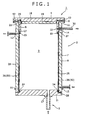
Fig. 2 is a flow sheet showing a high-pressure treatment facility provided with the high-pressure treatment apparatus; and -
Fig. 3 is a graph showing variations of heat flow rate relative to film heat-transfer coefficient. - A first embodiment of the present invention will be described based on the accompanying drawings. In the following description, supercritical treatment using supercritical fluid (supercritical carbon dioxide) is exemplified.
-
Figs. 1 and2 show a high-pressure treatment apparatus 1 according to this embodiment. The high-pressure treatment apparatus 1 includes: a pressure-resistant container 2 containing atreatment chamber 3 and having anopen end 52 which opens thetreatment chamber 3 in a specific direction (upwardly in the drawings); alid member 4 which seals the container (the treatment chamber 3) by being fitted to the pressure-resistant container 2 to close theopen end 52; a supply means 5 for supplying a process fluid to thetreatment chamber 3; acollar member 6 provided between thelid member 4 and the pressure-resistant container 2; and apartition wall 7 provided below thecollar member 6. Thepartition wall 7 divides the inside of the pressure-resistant container 2 into thetreatment chamber 3 on the inside and apartitioned chamber 25 on the outside, and isolates both thechambers treatment chamber 3 to thepartitioned chamber 25. - In this high-
pressure treatment apparatus 1, dyeing, plating, water-repellent coating or the like to a treatment object in a supercritical state, or hot isostatic press treatment (HIP treatment) is performed by supplying a high-temperature, high-pressure process fluid to thetreatment chamber 3. - The high-
pressure treatment apparatus 1 will be illustrated while taking the vertical direction in paper surface ofFig. 1 as vertical direction, the direction receding from the center of the pressure-resistant container 2 as outer circumferential direction (radially outward direction), and the direction approaching to the center as inner circumferential direction (radially inward direction). These directions are matched to the directions in the use of the high-pressure treatment apparatus 1. - The pressure-resistant container 2 includes a
container body 8 that is a pressure-resistant wall, and a bottom body 9. Thecontainer body 8 has a cylindrical shape having openings at upper and lower ends, and the bottom body 9 is installed to the lower end of thecontainer body 8 to close the lower end opening of thecontainer body 8. The upper end of thecontainer body 8 corresponds to theopen end 52. - The
container body 8 is formed in a cylindrical shape around an axis along the vertical directions. Aflange part 11 hanging to the radial outside over the other part is formed at the upper end of thecontainer body 8. Theflange part 11 has a flat upper surface, and thelid member 4 is fitted to this upper surface through thecollar member 6, whereby thetreatment chamber 3 is sealed. - The
container body 8 includes aninsert hole 12 formed in each of upper and lower parts thereof. The upper andlower insert holes treatment chamber 3, and extend through thecontainer body 8 in its thickness direction (radial direction) to allow the inside and outside of thecontainer body 8 to communicate with each other. The supply or discharge of heating medium is performed through the upper andlower insert holes container body 8 through thelower insert hole 12, and this heating medium is discharged out of thecontainer body 8 through theupper insert hole 12. - The
container body 8 also includes apipe insert hole 14 which extends through thecontainer body 8 in its radial direction similar to theinsert holes 12. Afluid conduit 30 for draining the process fluid out of thecontainer body 8 is inserted to thispipe insert hole 14. - The bottom body 9 is formed in a disk shape by a pressure-resistant material having acid resistance and pressure resistance (e.g., stainless steel). A
fitting part 16 projecting upwardly beyond the circumferential part is formed in a central portion of the bottom body 9, and thisfitting part 16 is fitted to the lower end of thecontainer body 8. - A through
hole 17 extending through the bottom body 9 in the vertical direction is formed in a position close to the center of the bottom body 9, and this throughhole 17 is connected to afluid passage 15 which will be described later. - Namely, in the pressure-resistant container 2 of this embodiment, the process fluid flows into the
treatment chamber 3 through the throughhole 17 of the bottom body 9 and discharges to the outside through afluid discharge port 22 of thepipe insert hole 14. - The
lid member 4 has alid body 18 on the upper side and aninner lid 19 on the lower side, which are vertically superposed one over other. - The
lid body 18 is formed in a disk shape by the same material as thecontainer body 8. Afitting part 20 projecting downwardly beyond the outer circumferential part is formed in a central portion of thelid body 18, and thisfitting part 20 is fitted to the upper end of thecontainer body 8. - The
inner lid 19 is formed in a disk shape by the same pressure-resistant material as the bottom body 9. Theinner lid 19 includes an annular recessed part opened toward the lower surface of thelid body 18, which is formed over the whole circumference of its periphery, and alip seal 21 is provided within the annular recessed part. - The
collar member 6 is provided between thelid member 4 and thecontainer body 8. Thecollar member 6 is a cylindrical body, with the periphery at the upper end thereof hanging to the radial outside over the other part in a flanged shape. Thecollar member 6 is attached to thecontainer body 8 so that this hanging part in the flanged shape is held between thelid member 4 and thecontainer body 8. The peripheral edge of the above-mentionedlip seal 21 contacts with the inner circumferential surface of thecollar member 6, whereby the gap between thecollar member 6 and thelid member 4 is sealed to maintain the air-tight state in thetreatment chamber 3. - The
collar member 6 includes thefluid discharge port 22 formed in a position corresponding to thepipe insert hole 14 of thecontainer body 8. Thefluid discharge port 22 radially extends through thecollar member 6, and the process fluid in thetreatment chamber 3 is discharged out of the high-pressure treatment apparatus 1 through thefluid discharge port 22. - The
partition wall 7 has a vertically opened cylindrical shape. The upper part of thepartition wall 7 is fitted to between the outer circumferential surface of the lower end of thecollar member 6 and the inner circumferential surface of thecontainer body 8. In response, afirst seal body 23 is provided on the lower outside surface of thecollar member 6, and thisfirst seal body 23 is closely fitted to the inner circumferential surface of the upper end of thepartition wall 7, whereby the air-tight state in thetreatment chamber 3 is maintained. The lower part of thepartition wall 7 is fitted to between the outer circumferential surface of thefitting part 16 of the bottom body 9 and the inner circumferential surface of the lower end of thecontainer body 8. In response, asecond seal body 24 is provided on the outer circumferential part of thefitting part 16, and thesecond seal body 24 is closely fitted to the inner circumferential surface of the lower end of thepartition wall 7, whereby the air-tight state in thetreatment chamber 3 is maintained. - The
partition wall 7 is disposed so as to cover the whole inside surface of thecontainer body 8 located below thecollar member 6, thereby dividing the inside of the pressure-resistant container 2 into thetreatment chamber 3 on the inside and the partitionedchamber 25 on the outside. Thepartition wall 7 is formed of a metallic material with a thickness smaller than that of thecontainer body 8, and provided to be spaced radially inwardly from thecontainer body 8. Thepartition wall 7 isolates both thechambers treatment chamber 3 on the inside to the partitionedchamber 25 on the outside. - The supply means 5 includes a
fluid passage 15 for resupplying the process fluid discharged from thetreatment chamber 3 to thetreatment chamber 3 after adjusting the temperature and pressure of the process fluid. - As the process fluid, although any fluid can be used in principle, a fluid excellent in diffusivity and solubility under the temperature and pressure of the critical point or more is preferably used. In this embodiment, supercritical carbon dioxide is used as the process fluid.
- The
fluid passage 15 includes thefluid conduit 30 for distributing the process fluid (supercritical carbon dioxide) from thefluid discharge port 22 to the throughhole 17, and anevaporator 31, aseparator 32, a condenser 33, aliquefaction tank 34, a cooler 35, afluid pump 36, and aheater 37 are provided on the course of thefluid conduit 30. - In the
fluid passage 15, supercritical carbon dioxide discharged from thetreatment chamber 3 is decompressed in theevaporator 31 to gasify the liquefied fluid. The thus-vaporized carbon dioxide is separated from impurities such as water mixed thereto in theseparator 32, and only the gas of carbon dioxide is recovered. The recovered gas of carbon dioxide is sent to the condenser 33, liquefied by cooling in the condenser 33, and stored in theliquefaction tank 34. - Although carbon dioxide is released when taking out a treatment object in the high-
pressure treatment apparatus 1, the carbon dioxide in thestorage tank 38 is supplied as occasion demands. - The high-pressure carbon dioxide in the
liquefaction tank 34 is sent to the cooler 35, and overcooled in the cooler 35. The carbon dioxide thus-liquefied is then sent to thetreatment chamber 3 by thefluid pump 36. If dye, functionalizing agent, water or the like is needed for treatment within thetreatment chamber 3, the dye, functionalizing agent, water or the like can be supplied from anentrainer tank 39 by an entrainer pump and mixed to the liquefied carbon dioxide. - The liquefied carbon dioxide is sent to the
heater 37 provided between thefluid pump 36 and thetreatment chamber 3. In theheater 37, the liquefied carbon dioxide is heated to a temperature of the critical point or higher and changed to supercritical carbon dioxide, and this supercritical carbon dioxide is supplied to thetreatment chamber 3. - The high-
pressure treatment apparatus 1 includes not only the supply means 5 for supplying the process fluid set to a desired temperature into thetreatment chamber 3 but also aheating medium passage 13 for supplying or filling the heating medium adjusted to a desired temperature also to the partitionedchamber 25 provided outside thetreatment chamber 3 through thepartition wall 7. The high-pressure treatment apparatus 1 includes the heat transfer control means which controls the transfer of heat between thetreatment chamber 3 and the partitionedchamber 25 by feeding the heating medium to the partitionedchamber 25, and the heat transfer control means includes theheating medium passage 13 for supplying the temperature-set heating medium to the partitionedchamber 25. - The partitioned
chamber 25 is a cylindrical space formed between the radial outside of thepartition wall 7 and thecontainer body 8, and can store the heating medium. The partitionedchamber 25 communicates with thelower insert hole 12 for supplying the heating medium from theheating medium passage 13 into the partitionedchamber 25 and theupper insert hole 12 for discharging the heating medium in the partitionedchamber 25 to theheating medium passage 13, and the upper and lower insert holes 12 and 12 are connected to each other through theheating medium passage 13. - The partitioned
chamber 25 includes a convection control means 26 for suppressing convection of heating medium within the partitionedchamber 25, and a heating medium distribution promoting means (not shown) for spreading the heating medium over the whole surface of thepartition wall 7. - The convection control means 26 is a structure for suppressing the convection of heating medium within the partitioned
chamber 25, which is disposed within the partitionedchamber 25. Examples of the convection control means 26 include a multilayer structure (e.g., honeycomb structure) including a plurality of plate bodies made of metal, quartz, ceramics or the like, which is aligned at vertical intervals, and a porous structure (e.g., glass wool) formed of the above-mentioned materials. Such a convection control means 26 regulates the vertical movement of the heating medium within the partitionedchamber 25 by being provided within the partitionedchamber 25, and consequently suppresses the convection of heating medium within the partitionedchamber 25, whereby the loss of heat from the treatment chamber resulting from the convection of medium can be reduced. Namely, the transfer of heat between the treatment chamber and the partitioned chamber can be suppressed. - The heating medium distribution promoting means is provided on at least one surface of the inner circumferential surface of the
container body 8 and the outer surface of thepartition wall 7 in the pressure-resistant container 2 so that the heating medium can be spread over the whole surface of thepartition wall 7. The heating medium distribution promoting means is formed in a plate-like shape so as to project toward the radial inside from the inner circumferential surface of thecontainer body 8 or toward the radial outside from the outer surface of thepartition wall 7, and guides the flow of medium within the partitionedchamber 25 so that the heating medium is spread over the whole surface of thepartition wall 7. As other examples of the heating medium distribution promoting means, the heating medium distribution promoting means may be composed of a rib continuously formed on the outer circumferential surface of thepartition wall 7 in a vertically spiral shape to guide the heating medium fed through thelower insert hole 12 to theupper insert hole 12, or composed of plate materials formed in a ring shape partially cut in the circumferential direction (substantially C-shape), which are stacked at vertical intervals with the cut parts being alternated. - The heating medium distribution promoting means as described above can prevent significant deformation of the
partition wall 7, for example, even in a case such that thepartition wall 7 swells toward the radial outside due to the pressure of the partitionedchamber 25 lower than that of thetreatment chamber 3. - The
heating medium passage 13 includes aheating medium conduit 40 for distributing the heating medium from theupper insert hole 12 to thelower insert hole 12, as shown inFig. 2 , and a compression means 43, aheat exchanger 44, apressure equalizing conductor 41, anaccumulator 42, aheating medium pump 55 and aheating medium tank 56 are provided on the course of theheating medium conduit 40. - In the
heating medium passage 13, heating medium discharged from the partitionedchamber 25 through theupper insert hole 12 is sent to the compression means 43. The compression means 43 is a compressor or pump capable of adjusting the pressure of the discharged heating medium, and the heating medium whose pressure is adjusted by the compression means 43 is sent to the heat exchanger 44 (temperature adjustment means). Theheat exchanger 44 heats or cools the heating medium to a predetermined temperature. The heating medium whose temperature is adjusted by theheat exchanger 44 is then resupplied to the partitionedchamber 25. Theheating medium passage 13 includes aheating medium tank 56 which receives and stores the heating medium discharged out of the partitionedchamber 25 through theupper insert hole 12 via a conduit not shown, and aheating medium pump 55 for feeding the heating medium from theheating medium tank 56 to theheating medium passage 13. - The heat transfer control means is configured to control transfer of heat between the
treatment chamber 3 and the partitionedchamber 25 by feeding heating medium into the partitionedchamber 25 with heating or cooling the heating medium to an appropriate temperature, or constituted by heating medium preliminarily filled in the partitionedchamber 25. The heat transfer control means in this embodiment includes a first heat transfer control means and a second heat transfer control means respectively according to the case of heating or cooling thetreatment chamber 3 and the case of thermally insulating thetreatment chamber 3 as described below. - The first heat transfer control means, which is used to heat or cool the
treatment chamber 3, is composed of theheat exchanger 44 in theheating medium passage 13 and theheating medium conduit 40 passing through theheat exchanger 44. The first heat transfer control means promotes the transfer of heat between thepartitioned chamber 25 and thetreatment chamber 3 through thepartition wall 7 by heating or cooling the heating medium discharged out of the partitionedchamber 25 to a predetermined temperature by use of the heat exchanger 44 (temperature adjustment means), and supplying the thus-adjusted high-temperature or low-temperature heating medium from thetreatment chamber 3 to the partitionedchamber 25. The heating medium is heated by theheat exchanger 44 when heating thetreatment chamber 3, and cooled when cooling it. - The heating medium whose temperature is adjusted to higher or lower in temperature than the
treatment chamber 3 or the externally temperature-set heating medium is not limited to those actually subjected to heating treatment or cooling treatment. This heating medium may be a fluid, e.g., tap water, having a substantially constant temperature without heating or cooling, the temperature being lower than that of the process fluid within thetreatment chamber 3. - The second heat transfer control means, which is used to minimize, when the treatment temperature of the
treatment chamber 3 is changed, the effect of this temperature change on the temperature of thecontainer body 8, is composed of a heating medium having heat insulating property. This heating medium may be preliminarily stored in theheating medium tank 56 provided in theheating medium passage 13 and supplied to the partitionedchamber 25 through theheating medium passage 13 by theheating medium pump 55 or compressor provided in theheating medium passage 13, or may be preliminarily filled in the partitionedchamber 25. This heating medium causes the partitionedchamber 25 to function as heat-insulating layer. - As the heating medium having heat insulating property, for example, a gas or liquid having thermal conductivity of 0.2 W/mK or less, preferably 0.1 W/mK or less can be used. Concretely, supercritical carbon dioxide (0.075 W/mK at 20 MPa, 340°K), nitrogen (0.033 W/mK at the same), argon (0.024 W/mK at the same) or the like as compressible gas, and alkyldiphenyl (0.14 W/mK at 60°K), fluorine-based heating medium GALDEN HT (0.063 W/mK at 60°K) or the like as liquid are preferably used.
- Such a heating medium having heat insulating property can reduce the rate of heat transfer between the
partitioned chamber 25 and thetreatment chamber 3 through thepartition wall 7 to suppress a sudden temperature change of thetreatment chamber 3 by being supplied to the partitionedchamber 25, and also can suppress the transfer of heat between thepartitioned chamber 25 and thetreatment chamber 3 through thepartition wall 7 to thermally insulate thetreatment chamber 3 by being preliminarily filled in the partitionedchamber 25. - The temperature of the above-mentioned heating medium can be set to the same temperature as the process fluid in the
treatment chamber 3. This further enhances the effect of suppressing the transfer of heat (heat exchange) between thepartitioned chamber 25 and thetreatment chamber 3 through thepartition wall 7. - The heating/cooling or decompression of the partitioned
chamber 25 by the heat transfer control means causes a pressure difference between thepartitioned chamber 25 and thetreatment chamber 3, and this pressure difference causes plastic deformation of thepartition wall 7 and brings it into breakage. Therefore, the high-pressure treatment apparatus 1 of the present invention includes a partition wall protection means which prevents thepartition wall 7 from being deformed by a pressure difference caused between thetreatment chamber 3 and the partitionedchamber 25 due to a temperature difference caused by the heat transfer control means. - The high-
pressure treatment apparatus 1 of this embodiment includes, as the partition wall protection means, use of elastic deformation of thepartition wall 7 and a pressure control means for reducing the above-mentioned pressure difference. - With respect to the use of elastic deformation of the
partition wall 7, thepartition wall 7 is formed of a material easy to elastically deform. When the partitionedchamber 25 becomes higher in pressure than thetreatment chamber 3, thepartition wall 7 elastically deforms to swell toward thetreatment chamber 3 to thereby increase the volume of the partitionedchamber 25 just by the amount of this elastic deformation, whereby the partitionedchamber 25 and thetreatment chamber 3 are equalized in pressure. When thetreatment chamber 3 becomes higher in pressure than the partitionedchamber 25, reversely, thepartitioned wall 7 elastically deforms to recess toward the partitionedchamber 25 to thereby decrease the volume of the partitionedchamber 25 just by the amount of this elastic deformation, whereby the partitionedchamber 25 and thetreatment chamber 3 are equalized in pressure. To form thepartitioned wall 7 by use of the material easy to elastic deform provides the effect of further suppressing the plastic deformation of the partitionedwall 7 itself, in addition to rapid pressure equalization between thepartitioned chamber 25 and thetreatment chamber 3 by use of the elastic deformation. - The above-mentioned pressure control means includes the following first to fourth pressure control means.
- The first pressure control means is mainly composed of the
pressure equalizing conductor 41. Thepressure equalizing conductor 41 includes a conduction pipe (pressure pipe) 45, and amovable body 46 freely moving within theconduction pipe 45. One end of theconduction pipe 45 communicates with theheating medium conduit 40, and the other end communicates with the middle between theheater 37 and the high-pressure treatment apparatus 1 in thefluid conduit 30. Themovable body 46 is provided within theconduction pipe 45 so that it can move within theconduction pipe 45 while dividing the inside of theconduction pipe 45 into a chamber on theheating medium conduit 40 side (thepartitioned chamber 25 side) and a chamber on thefluid passage 15 side (thetreatment chamber 3 side), and sealing theconduction pipe 45 to arrest leak of the heating medium on theheating medium conduit 40 side (thepartitioned chamber 25 side) to thefluid passage 15 and leak of the process fluid on thefluid passage 15 side (thetreatment chamber 3 side) to theheating medium passage 13. - For example, when the partitioned
chamber 25 becomes higher in pressure than thetreatment chamber 3, the pressure of the heating medium in theheating medium pipe 40 is increased more than that of the process fluid in thefluid conduit 30, and this pressure difference causes themovable body 46 to move toward thefluid conduit 30 within theconduction pipe 45 to increase the pressure on thetreatment chamber 3 side just by the amount of the movement, whereby the partitionedchamber 25 and thetreatment chamber 3 are equalized in pressure. When the partitionedchamber 25 becomes lower in pressure than thetreatment chamber 3, a pressure difference reverse to the above causes themovable body 46 to move toward theheating medium conduit 40 within theconduction pipe 45 to reduce the pressure on thetreatment chamber 3 side just by the amount of the movement, whereby the partitionedchamber 25 and thetreatment chamber 3 are equalized in pressure. - In the first pressure control means, since the
movable body 46 immediately reacts to the pressure difference caused between thepartitioned chamber 25 and thetreatment chamber 3, even in the event of a sudden pressure difference between thepartitioned chamber 25 and thetreatment chamber 3, the pressure equalization between thepartitioned chamber 25 and thetreatment chamber 3 can be rapidly performed in response to the pressure difference to protect thepartition wall 7 from deformation. - The second pressure control means is configured to resolve the pressure difference between the
heating medium conduit 40 and thefluid conduit 30 by moving a part of the heating medium or process fluid between the both, and includes apipe 47 provided between theheating medium conduit 40 and thefluid conduit 30 to directly connect the both. Thepipe 47 includes an on-offvalve 49 that is an opening and closing part switchable to an open state to open the pipe and to a close state to close the pipe. The on-offvalve 49 can be opened, for example, only when the pressure difference between thepartitioned chamber 25 and thetreatment chamber 3 is increased such that its reduction is needed. Consequently, the heating medium or process fluid is partially moved from the high-pressure side to the low-pressure side through thepipe 47 to equalize the pressures of the partitionedchamber 25 and thetreatment chamber 3. Further, it is also possible to attain automatic control for pressure equalization by providing respective pressure detectors of the partitionedchamber 25 and thetreatment chamber 3, and a controller which opens the on-off valve when the difference between detection values of these pressure detectors exceeds a predetermined value. - With respect to the second pressure control means, a form without the on-off
valve 49 is also considered. For example, in a form shown inFig. 2 , since a pipe on the upstream side of thetreatment chamber 3 in the pressure-resistant container 1, or a pipe for supplying process fluid to thetreatment chamber 3 communicates with a pipe for supplying heating medium to the partitionedchamber 25, the process fluid in thetreatment chamber 3 never flows into the partitionedchamber 25 even if thepipe 47 is regularly opened by the omission of the on-offvalve 49. Since the process fluid flowing into thetreatment chamber 3 is free from impurities by being passed through theseparator 32, the problem of inclusion of impurities to the partitionedchamber 25 is never caused even if the fluid flows into the partitionedchamber 25. - To maintain the heat control performance using the heating medium at high level, it is preferred to perform the opening and closing by the on-off
valve 49. When further sure avoidance of mixing of the heating medium with the process fluid is needed, only discharge of a part of the high-pressure side fluid (heating medium or process fluid) can be performed. - The second pressure control means can be suitably used, for example, when the heating medium and the process fluid have the same or extremely similar properties, and can be mixed.
- The third pressure control means is mainly composed of the compression means 43. The compression means 43 equalizes the pressures of the
treatment chamber 3 and the partitionedchamber 25 by raising the pressure in the partitionedchamber 25 while raising the pressure in thetreatment chamber 3 by use of thefluid pump 36. The adjustment of pressure is performed by use of a pressure gauge not shown. - The fourth pressure control means is mainly composed of the
accumulator 42. Theaccumulator 42 is a container formed so as to communicate with theheating medium conduit 40 and to be capable of storing high-pressure heating medium. - An openable and
closable valve 48 is provided between the container constituting theaccumulator 42 and theheating medium conduit 40, and the high-pressure heating medium in the container can be sent to the partitionedchamber 25 through theheating medium conduit 40 by opening thevalve 48. Consequently, when thetreatment chamber 3 becomes higher in pressure than the partitionedchamber 25, thevalve 48 is opened to send the high-pressure heating medium in the container to the partitionedchamber 25 through theheating medium conduit 40, whereby the partitionedchamber 25 and thetreatment chamber 3 can be equalized in pressure. - The
valve 48 can be omitted. For example, a shrinkable partition wall of rubber or the like is provided within theaccumulator 42, and the partition wall of rubber or the like swells upward within theaccumulator 42, when thetreatment chamber 3 becomes higher in pressure than the partitionedchamber 25, to compress the high-pressure gas on the upper side, whereby the pressure equalization can be also attained. - The present invention will be described further in detail in reference to examples.
- In Example 1, the high-
pressure treatment apparatus 1 was used to form a water-repellent coat layer on a surface of a treatment object of hydrocarbon resin in the presence of supercritical carbon dioxide. - In the formation of the water-repellent coat layer, the treatment object and a coating agent were prepared according to the following procedures. The treatment object is a resin piece of a predetermined size formed of hydrocarbon resin (polyimide resin). The coating agent contains a raw material monomer of the water-repellent coat layer and a polymerization initiator. The raw material monomer is a mixture of a fluorine monomer (3,8,4,4,5,5,6,6,7,7,8,8,9,9,10,10,10-heptadecafluorooctyl ethyl methacrylate) and a hydrocarbon monomer (n-stearyl acrylate), and the coating agent was prepared by mixing the raw material monomer and the polymerization initiator (azobisisobutyronitrile) so that the both have the same parts by weight.
- Water-repellent coating was performed by use of the thus-prepared treatment object and coating agent. To perform the water-repellent coating in the high-
pressure treatment apparatus 1, acontainer body 8 of 100 mm in thickness was used, and apartition wall 7 of 5 mm in thickness was disposed along the inside surface thereof. - The operation is performed as follows. Hot water of 55°C is supplied to the partitioned
chamber 25 through theheating medium passage 13, and thetreatment chamber 3 is adjusted to the temperature of 50°C by causing transfer of heat between thepartitioned chamber 25 and thetreatment chamber 3 through thepartition wall 7 by use of the first heat transfer control means. In this case, a pressure of about 0.1 MPa is applied to the heating medium since thetreatment chamber 3 is opened to the atmosphere. - After the
treatment chamber 3 is sufficiently raised in temperature, the treatment object and the coating agent are put into thetreatment chamber 3, and thetreatment chamber 3 is sealed by thelid member 4. Thefluid pump 36 feeds compressed CO2 from thestorage tank 38 to thetreatment chamber 3 through thefluid conduit 30. The supply of CO2 is continued until the inside of thetreatment chamber 3 reaches 15 MPa. At that time, the pressures in thetreatment chamber 3 and the partitionedchamber 25 can be raised while preventing the plastic deformation of thepartition wall 7 and equalizing the internal pressure of the partitionedchamber 25 with the internal pressure of thetreatment chamber 3 by use of the elastic deformation of thepartition wall 7 and the first to fourth pressure control means. - After the lapse of a fixed time (about 120 minutes) after the
treatment chamber 3 reaches 50°C and 15 MPa, hot water of 85°C is supplied into the partitionedchamber 25 through theheating medium passage 13, and transfer of heat between thepartitioned chamber 25 and thetreatment chamber 3 through thepartition wall 7 is performed using the first heat transfer control means, whereby the temperature of the process fluid in thetreatment chamber 3 is raised to 80°C. The polymerization initiator in the coating agent is decomposed by raising the temperature of thetreatment chamber 3 from 50°C to 80°C, and copolymerization of the fluorine monomer and the hydrocarbon monomer proceeds. - Next, in the high-
pressure treatment apparatus 1, the efficiency of heat transfer from the heating medium in the partitionedchamber 25 to the process fluid in thetreatment chamber 3 was computationally determined. -
Fig. 3 shows the results of determination of heat flow rate at a temperature difference of 35°C transferring from the partitionedchamber 25 to thetreatment chamber 3, relative to film heat-transfer coefficients in a natural convection state to a forced convection state of thetreatment chamber 3. The heat flow rate was calculated with preconditions of film heat-transfer coefficient on the heating medium side of 1000 W/m2°C, and heat conductivity of thecontainer body 8 and thepartition wall 7 of 16.2 W/m°C. - In
Fig. 3 , the high-pressure treatment apparatus 1 including thecontainer body 8 and thepartition wall 7 provided on the inside thereof is used in Example 1, and a high-pressure treatment apparatus including thepartition wall 7 provided outside thecontainer body 8, is used in Conventional Example 1. -
Fig. 3 shows that the heat flow rate transferring to thetreatment chamber 3 is larger in Example 1 than in Conventional Example 1 irrespective of the natural convection state or forced convection state in thetreatment chamber 3, and the high-pressure treatment apparatus 1 of Example 1 using both the heat transfer control means and the partition wall protection means can more efficiently transfer heat. Particularly, the heat flow rate in Example 1 tends to remarkably increase as thetreatment chamber 3 gets close to the forced convection state, compared with Conventional Example 1, although the heat flow rate in Example 1 is slightly larger than in Conventional Example 1 when thetreatment chamber 3 is in a state close to the natural convection state (when the film heat-transfer coefficient is low), and this shows that the heat efficiency is remarkably improved in the high-pressure treatment apparatus 1 of the present invention as the process fluid is supplied more to thetreatment chamber 3 through thefluid passage 15. - The high-
pressure treatment apparatus 1 of Example 2 will be then described. In the high-pressure treatment apparatus 1 of Example 2, thetreatment chamber 3 is cooled after performing HIP treatment to a treatment object at high temperature and high pressure in thetreatment chamber 3. - The high-
pressure treatment apparatus 1 of Example 2 includes a pressure-resistant container 2 having an inside diameter of 1500 mm, and apartition wall 7 of 20 mm in thickness provided in the inner part of the pressure-resistant container 2. Thetreatment chamber 3 is formed inside thepartition wall 7, and process fluid of 150°C is stored in thetreatment chamber 3. - In the high-
pressure treatment apparatus 1 of Example 2, the partitionedchamber 25 is formed outside thepartition wall 7. A heating medium (cooling water) ofwater temperature 35°C is distributed to the partitionedchamber 25, and the partitionedchamber 25 includes the first heat transfer control means. - In the high-
pressure treatment apparatus 1 of Example 2, the heat passage coefficient in transfer of heat from the heating medium in the partitionedchamber 25 to the process fluid in thetreatment chamber 3 was computationally determined. The high-pressure treatment apparatus 1 of Example 2 in the following calculation includes acontainer body 8 and thepartition wall 7 provided inside it, and the high-pressure treatment apparatus of Conventional Example 2 includes acontainer body 8 having an outside diameter of 2000 mm and an inside diameter of 1500 mm, and apartition wall 7 provided outside it. - The heat passage coefficient K in the high-
pressure treatment apparatus 1 of Conventional Example 2 can be given by the following expression (1), when the radius r2 of outer diameter of the pressure-resistant container 2 is 1 m, the radius r1 of inside diameter of the pressure-resistant container 2 is 0.75 m, each of the heat-transfer coefficient h1 of process fluid and the heat-transfer coefficient h2 of heating medium is 400 W/m2K, and the heat conductivity λ of thecontainer body 8 is 37.3 W/mK. -

- On the other hand, when the heat passage coefficient K determined by the expression (1) is used, the heat quantity q transferring from the
treatment chamber 3 to the partitionedchamber 25 through thecontainer body 8 per 1 m of the pressure-resistant container is as shown in the following expression (2), wherein the temperature of process fluid is T1f (K), and the temperature of heating medium is T2f (K). -

- The high-
pressure treatment apparatus 1 of Example 2 will be then described. The difference of the high-pressure treatment apparatus of Conventional Example 2 from Example 2 is that thepartition wall 7 is provided outside thecontainer body 8 in Conventional Example 2, while thepartition wall 7 is provided inside thecontainer body 8 in Example 2. Detailed description for Conventional Example 2 is omitted since points other than the above-mentioned point are the same as Example 2. - The heat passage coefficient in the high-
pressure treatment apparatus 1 of Conventional Example 2 can be given by the following expression (3) similar to the case of Example 2. -

- On the other hand, when the heat passage coefficient determined by the expression (3) is used, the heat quantity transferring from the
treatment chamber 3 to the partitionedchamber 25 through thepartition chamber 7 per 1 m of the pressure-resistant container is as shown in the following expression (4). -

- The results of the above-mentioned expressions (2) and (4) show that when the high-
pressure treatment apparatus 1 of Example 2 is used, the heat quantity transferring from thetreatment chamber 3 to the partitionedchamber 25 through thepartition wall 7 is about 1.9 times the case of Conventional Example 2. Therefore, the high-pressure treatment apparatus 1 of the present invention can be determined to be capable of efficiently cooling or heating process fluid within thetreatment chamber 3, even in use for HIP treatment, by using both the heat transfer control means and the partition wall protection means. - The present invention is never limited to each of the above-mentioned embodiments, and the shape, structure, material, combination, etc. of each member can be appropriately changed without departing from the gist of the present invention.
- In the above-mentioned embodiments, the partition wall protection means can suppress, in addition to the deformation of the
partition wall 7 due to a pressure difference caused between thetreatment chamber 3 and the partitionedchamber 25 resulting from a temperature difference caused by the heat transfer control means, the deformation of thepartition wall 7 due to a pressure difference caused between thetreatment chamber 3 and the partitionedchamber 25 resulting from a factor other than the temperature difference caused by the heat transfer control means. - The use application of the high-pressure treatment apparatus according to the present invention is never limited to the dyeing, plating or water-repellent coating in supercritical fluid, or HIP treatment as described above. For example, the high-pressure treatment apparatus can be applied also to washing in supercritical fluid, HIP needing high-temperature, high-pressure atmosphere, and uses other than supercritical treatment.
- With respect to the first to third heat transfer control means and the first to fourth pressure control means according to the above-mentioned embodiments, any one of them may be provided, or a plurality of means may be provided in a composite manner.
- As described so far, the present invention provides a high-pressure treatment apparatus, capable of efficiently performing adjustment of pressure or temperature of a treatment chamber for a short time without remarkable increase in overall size or complication of the apparatus. This high-pressure treatment apparatus includes: a pressure-resistant container having a pressure-resistant wall which surrounds the treatment chamber inside and an open end which opens the treatment chamber to the outside; a lid member installed to the pressure-resistant container to seal the treatment chamber by closing the open end of the pressure-resistant container; a supply means for supplying a process fluid to the treatment chamber; a partition wall provided along the inside surface of the pressure-resistant container while having a thickness smaller than that of the pressure-resistant wall to form a partitioned chamber with the inside surface, the partition wall isolating the partitioned chamber from the treatment chamber so as to prevent inflow of the process fluid from the treatment chamber to the partitioned chamber; and a heat transfer control means which controls transfer of heat between the treatment chamber and the partitioned chamber by heating or cooling a heating medium outside the container and feeding the resulting heating medium into the partitioned chamber.
- According to this apparatus, since the partition wall smaller in thickness than the pressure-resistant wall is provided inside the pressure-resistance wall of the pressure-resistant container, and the heating medium temperature-adjusted by the heat transfer control means is fed into the partitioned chamber formed between the partition wall and the pressure-resistant wall, the smaller thickness of the partition wall promotes the transfer of heat between the heating medium within the partitioned chamber and the fluid in the treatment chamber, and this assists to reduce the heating time or cooling time within the pressure-resistant container. Namely, the heat transfer control means can efficiently change the pressure or temperature of the treatment chamber in a short time or maintain its temperature by adjusting the temperature of the heating medium fed to the partitioned chamber from the outside, and various high-pressure treatments can be thus performed in a short cycle time. Since it is not necessary to provide a temperature adjustment device such as a heater in the partitioned chamber between the partition wall and the inside wall of the pressure-resistant container, the treatment chamber on the inside of the partition wall can be relatively increased in size to ensure a large treatment space for a treatment object. On the other hand, the volume of the partitioned chamber can be reduced to adjust the temperature of the partitioned chamber in a short time.
- The heat transfer control means can heat the inside of the treatment chamber by, for example, feeding the heating medium into the partitioned chamber while adjusting its temperature to be higher than that of the process fluid to transfer heat from the partitioned chamber to the treatment chamber through the partition wall. It can also cool the inside of the treatment chamber by feeding the heating medium into the partitioned chamber while adjusting its temperature to be lower than that of the process fluid to reversely transfer the heat from the treatment chamber to the partitioned chamber through the partition wall. Further, the heat transfer control means can thermally insulate the inside of the treatment chamber by feeding the heating medium into the partitioned chamber while adjusting its temperature to be equal to that of the process fluid in the treatment chamber to suppress the transfer of heat between the treatment chamber and the partitioned chamber.
- The heat transfer control means can suppress the transfer of heat between the treatment chamber and the partitioned chamber to thermally insulate the treatment chamber or gently change the temperature of the treatment chamber also by feeding, as the heating medium, a fluid having heat insulating property into the partitioned chamber.
- Further, a convection suppressing means for suppressing convection of the heating medium within the partitioned chamber is preferably provided in the partitioned chamber. The convention suppressing means can suppress the transfer of heat between the treatment chamber and the partitioned chamber resulting from the convection of heating medium within the partitioned chamber by suppressing this convection of heating medium.
- The apparatus according to the present invention more preferably includes a heating medium distribution promoting means provided on at least one surface of the inside surface of the pressure-resistant container and the outer surface of the partition wall to spread the heating medium over the whole surface of the partition wall. The heating medium distribution promoting means allows temperature control for equalizing the temperature within the treatment chamber by spreading the heating medium over the whole surface of the partition wall.
- In the high-pressure treatment apparatus according to the present invention, if a difference between the pressure in the treatment chamber and the pressure in the partitioned chamber is extended due to fluctuation of pressure in the treatment chamber, temperature change in the partitioned chamber or the like, a bending load corresponding to the pressure difference acts on the partition wall. The partition wall may plastically deforms upon action of a large load thereon, since the partition wall is formed thinly for the purpose of promoting the heat exchange as described above.
- However, the high-pressure treatment apparatus according to the present invention can effectively suppress the deformation of the partition wall resulting from a pressure difference between the partitioned chamber and the treatment chamber by further including a pressure control means for controlling the pressure in the partitioned chamber and the pressure in the treatment chamber so as to suppress occurrence of the above-mentioned pressure difference.
- Concretely, it is preferable that the pressure control means includes a pressure pipe having one end communicating with the partitioned chamber and the other end communicating with the treatment chamber; and a movable body provided within the pressure chamber so that it can move within the pressure pipe while dividing the inside of the pressure pipe into a chamber on the partitioned chamber side and a chamber on the treatment chamber side and sealing the inside of the pressure pipe to arrest the distribution of the heating medium and the process fluid between the chamber on the partitioned chamber side and the chamber on the treatment chamber side, and that the movable body moves toward the low-pressure side in the event of the pressure difference, whereby the pressure difference is reduced. This type of pressure control means can automatically reduce the difference between the pressure in the partitioned chamber and the pressure in the treatment chamber by a simple structure such that only the movable body is provided within the pressure pipe.
- In the pressure control means, it is also effective to include a pipe provided between the partitioned chamber and the treatment chamber so that the both communicate with each other, and an on-off valve switchable to a state for opening the pipe and a state for closing the pipe. This type of pressure control means can isolate the partitioned chamber from the treatment chamber, for example, by closing the on-off valve to close the pipe when the pressure difference is less than a fixed value, and also can rapidly reduce the pressure difference, for example, by opening the on-off valve to open the pipe only when the pressure difference is equal to or larger than the fixed value. Further, automatic control for reducing the pressure difference can be also attained by providing pressure detectors for detecting the pressure in the partitioned chamber and the pressure in the treatment chamber respectively, and a controller which opens the on-off valve only when the difference between both the pressures detected by the detectors is equal to or larger than the fixed value.
- Otherwise, the above-mentioned pressure control means may include a compression means for reducing the pressure difference by compressing the heating medium in the partitioned chamber, or may include an accumulator for reducing the pressure difference by storing part of the process fluid in the treatment chamber.
- In addition to these pressure control means, it is also effective, as a means for suppressing the plastic deformation of the partition wall, to provide the partition wall so that it can deflect toward both the partitioned chamber and the treatment chamber, and reduce, in the event of the occurrence of a pressure difference between the partitioned chamber and the treatment chamber, the pressure difference by the deflection of the partition wall toward the low pressure side.
- The high-pressure treatment apparatus according to the present invention may include a pressure-resistant container having a pressure-resistant wall which surrounds the treatment chamber inside and an open end which opens the treatment chamber to the outside; a lid member installed to the pressure-resistant container to seal the treatment chamber by closing the open end of the pressure-resistant container; a supply means for supplying a process fluid to the treatment chamber; a partition wall provided along the inside surface of the pressure-resistant container while having a thickness smaller than that of the pressure-resistant wall to form a partitioned chamber with the inside surface, the partition wall isolating the partitioned chamber from the treatment chamber so as to prevent inflow of the process fluid from the treatment chamber to the partitioned chamber; and a heating medium filled in the partitioned chamber to suppress heat transfer between the treatment chamber and the partitioned chamber.
- In this apparatus, also, the heating medium filled in the partitioned chamber can suppress the transfer of heat between the treatment chamber and the partitioned chamber to thermally insulate the treatment chamber or gently change the temperature of the treatment chamber.
- When this heating medium is composed of a fluid having heat insulating property, particularly, the function as heat-insulating layer can be imparted to the partitioned chamber.
Claims (15)
- A high-pressure treatment apparatus for performing high-pressure treatment of a treatment object within a treatment chamber, comprising:a pressure-resistant container having a pressure-resistant wall which surrounds the treatment chamber inside and an open end which opens the treatment chamber to the outside;a lid member installed to said pressure-resistant container to seal the treatment chamber by closing the open end of said pressure-resistant container;a supply means for supplying a process fluid to the treatment chamber;a partition wall provided along the inside surface of said pressure-resistant container while having a thickness smaller than that of the pressure-resistant wall to form a partitioned chamber with the inside surface, said partition wall isolating the partitioned chamber from the treatment chamber within said pressure-resistant container so as to prevent inflow of the process fluid from the treatment chamber to the partitioned chamber; anda heat transfer control means which controls transfer of heat between the treatment chamber and the partitioned chamber by heating or cooling a heating medium outside said container and feeding the resulting heating medium into the partitioned chamber.
- The high-pressure treatment apparatus according to claim 1, wherein said heat transfer control means heats the treatment chamber through said partition wall by feeding the heating medium into the partitioned chamber while adjusting its temperature to be higher than that of the process fluid.
- The high-pressure treatment apparatus according to claim 1, wherein said heat transfer control means cools the treatment chamber through said partition wall by feeding the heating medium into the partitioned chamber while adjusting its temperature to be lower than that of the process fluid.
- The high-pressure treatment apparatus according to claim 1, wherein said heat transfer control means suppresses the transfer of heat between the treatment chamber and the partitioned chamber by feeding the heating medium into the partitioned chamber while adjusting its temperature to be equal to that of the process fluid.
- The high-pressure treatment apparatus according to claim 1, wherein said heat transfer control means feeds, as the heating medium, a fluid having heating insulating property to the partitioned chamber.
- The high-pressure treatment apparatus according to claim 1, wherein the apparatus further includes a convection suppressing means provided in the partitioned chamber to suppress convection of the heating medium within the partitioned chamber.
- The high-pressure treatment apparatus according to claim 1, wherein the apparatus further includes a heating medium distribution promoting member provided on at least one surface of the inside surface of said pressure-resistant container and the outer surface of said partition wall to spread the heating medium over the whole surface of said partition wall.
- The high-pressure treatment apparatus according to claim 1, wherein the apparatus further includes a pressure control means which controls the pressure in the partitioned chamber and the pressure in the treatment chamber to suppress occurrence of a pressure difference between the partitioned chamber and the treatment chamber.
- The high-pressure treatment apparatus according to claim 8, wherein said pressure control means includes a pressure pipe having one end communicating with the partitioned chamber and the other end communicating with the treatment chamber; and a movable body provided within the pressure chamber so that it can move within said pressure pipe while dividing the inside of said pressure pipe into a chamber on the partitioned chamber side and a chamber on the treatment chamber side and sealing the inside of said pressure pipe to arrest the distribution of the heating medium and the process fluid between the chamber on the partitioned chamber side and the chamber on the treatment chamber side, and said movable body moves toward the low-pressure side in the event of the pressure difference, whereby the pressure difference is reduced.
- The high-pressure treatment apparatus according to claim 8, wherein said pressure control means includes a pipe provided between the partitioned chamber and the treatment chamber so that both the chambers communicate with each other, and an opening and closing part switchable to a state for opening said pipe and a state for closing said pipe.
- The high-pressure treatment apparatus according to claim 8, wherein said pressure control means includes a compression means for reducing the pressure difference by compressing the heating medium in the partitioned chamber.
- The high-pressure treatment apparatus according to claim 8, wherein the partition wall protection means includes an accumulator for reducing the pressure difference by storing part of the process fluid in the treatment chamber.
- The high-pressure treatment apparatus according to claim 1, wherein said partition wall is provided so that it can deflect toward both the partitioned chamber and the treatment chamber, and said partition wall is deflected to the low-pressure side in the event of a pressure difference between the partitioned chamber and the treatment chamber, whereby the pressure difference is reduced.
- A high-pressure treatment apparatus for performing high-pressure treatment of a treatment object within a treatment chamber, comprising:a pressure-resistant container having a pressure-resistant wall which surrounds the treatment chamber inside and an open end which opens the treatment chamber to the outside;a lid member installed to said pressure-resistant container to seal the treatment chamber by closing the open end of said pressure-resistant container;a supply means for supplying a process fluid to the treatment chamber;a partition wall provided along the inside surface of said pressure-resistant container while having a thickness smaller than that of the pressure-resistant wall to form a partitioned chamber with the inside surface, said partition wall isolating the partitioned chamber from the treatment chamber within said pressure-resistant container so as to prevent inflow of the process fluid from the treatment chamber to the partitioned chamber; anda heating medium filled in the partitioned chamber to suppress heat transfer between the treatment chamber and the partitioned chamber.
- The high-pressure treatment apparatus according to claim, 14, wherein said heating medium is composed of a fluid having heat insulating properly
Applications Claiming Priority (2)
| Application Number | Priority Date | Filing Date | Title |
|---|---|---|---|
| JP2008159202 | 2008-06-18 | ||
| PCT/JP2009/060346 WO2009154089A1 (en) | 2008-06-18 | 2009-06-05 | High‑pressure treatment apparatus |
Publications (2)
| Publication Number | Publication Date |
|---|---|
| EP2289615A1 true EP2289615A1 (en) | 2011-03-02 |
| EP2289615A4 EP2289615A4 (en) | 2016-11-16 |
Family
ID=41434005
Family Applications (1)
| Application Number | Title | Priority Date | Filing Date |
|---|---|---|---|
| EP09766537.6A Withdrawn EP2289615A4 (en) | 2008-06-18 | 2009-06-05 | High pressure treatment apparatus |
Country Status (6)
| Country | Link |
|---|---|
| US (1) | US8573962B2 (en) |
| EP (1) | EP2289615A4 (en) |
| JP (1) | JP5546164B2 (en) |
| KR (1) | KR101246416B1 (en) |
| TW (1) | TW201009278A (en) |
| WO (1) | WO2009154089A1 (en) |
Cited By (3)
| Publication number | Priority date | Publication date | Assignee | Title |
|---|---|---|---|---|
| DE102011051269A1 (en) * | 2011-06-22 | 2012-12-27 | DIL Deutsches Institut für Lebensmitteltechnik e.V. | Charging tank and method for simultaneous high pressure and temperature treatment of a food in a high pressure boiler |
| WO2014121953A1 (en) * | 2013-02-11 | 2014-08-14 | Robert Bosch Gmbh | Sterilising device and sterilisation method having energy recovery |
| FR3043922A1 (en) * | 2015-11-25 | 2017-05-26 | Dfd - Dense Fluid Degreasing | METHOD AND DEVICE FOR SUPERCRITICAL FLUID TREATMENT WITH GRAVITY PASSIVE PUMPING |
Families Citing this family (10)
| Publication number | Priority date | Publication date | Assignee | Title |
|---|---|---|---|---|
| EP2781916A1 (en) * | 2013-03-22 | 2014-09-24 | Biotage AB | Coupling module |
| JP6189650B2 (en) * | 2013-06-07 | 2017-08-30 | 昭和電工ガスプロダクツ株式会社 | Supercritical processing equipment |
| US10765968B2 (en) | 2014-08-19 | 2020-09-08 | Supercritical Fluid Technologies, Inc. | Systems and methods for supercritical fluid chromatography |
| WO2016028521A2 (en) | 2014-08-19 | 2016-02-25 | Supercritical Fluid Technologies, Inc. | Supercritical fluid chromatography system |
| US11913685B2 (en) | 2014-08-19 | 2024-02-27 | Supercritical Fluid Technologies, Inc. | Cooling loop with a supercritical fluid system using compressed refrigerant fluid flow with a positive Joule Thomson coefficient |
| WO2018071884A1 (en) | 2016-10-14 | 2018-04-19 | Supercritical Fluid Technologies, Inc. | Cooling loop with a supercritical fluid system using compressed refrigerant fluid flow with a positive joule-thomson coefficient |
| CN110678319B (en) | 2017-03-23 | 2021-11-05 | 昆特斯技术公司 | Pressing equipment |
| JP6891301B2 (en) * | 2017-05-31 | 2021-06-18 | キンタス・テクノロジーズ・エービーQuintus Technologies AB | Press component |
| FR3071179B1 (en) * | 2017-09-18 | 2019-09-13 | Commissariat A L'energie Atomique Et Aux Energies Alternatives | COOLING HOT ISOSTATIC PRESS RELIEF |
| WO2020142753A1 (en) | 2019-01-04 | 2020-07-09 | Supercritical Fluid Technologies, Inc. | Interchangeable chromatography cartridge adapter system |
Family Cites Families (15)
| Publication number | Priority date | Publication date | Assignee | Title |
|---|---|---|---|---|
| CH353341A (en) * | 1957-04-29 | 1961-04-15 | Ciba Geigy | Autoclave |
| DE3261561D1 (en) * | 1982-01-08 | 1985-01-31 | Ernst Haage Apparatebau Und La | Heatable high-pressure autoclave |
| US4670404A (en) * | 1985-04-22 | 1987-06-02 | Fike Corporation | Micro-scale chemical process simulation methods and apparatus useful for design of full scale processes, emergency relief systems and associated equipment |
| JPH07117345B2 (en) | 1988-07-07 | 1995-12-18 | 株式会社神戸製鋼所 | High temperature and high pressure processing method and apparatus |
| JPH0765855B2 (en) | 1988-07-07 | 1995-07-19 | 株式会社神戸製鋼所 | Hot isostatic press |
| JPH0221191A (en) | 1988-07-07 | 1990-01-24 | Kobe Steel Ltd | Hot hydrostatic pressurizing device |
| JP2528180B2 (en) | 1989-03-18 | 1996-08-28 | 株式会社神戸製鋼所 | High pressure processing equipment |
| JP3477236B2 (en) | 1994-03-28 | 2003-12-10 | 株式会社神戸製鋼所 | Pressure control method and reaction processing device |
| SE509518C2 (en) * | 1997-06-13 | 1999-02-08 | Asea Brown Boveri | Device for thermostatic pressing |
| JP2003240261A (en) * | 2002-02-15 | 2003-08-27 | Sharp Corp | Integrated type air conditioner |
| JP4204253B2 (en) * | 2002-05-15 | 2009-01-07 | 株式会社神戸製鋼所 | Hot isostatic press |
| JP4327410B2 (en) * | 2002-05-29 | 2009-09-09 | オルガノ株式会社 | Batch type hydrothermal reactor and hydrothermal reactor |
| JP4304276B2 (en) * | 2004-03-31 | 2009-07-29 | 独立行政法人産業技術総合研究所 | Efficient heat insulation method and apparatus for high pressure apparatus |
| FR2891162B1 (en) * | 2005-09-28 | 2008-05-09 | Commissariat Energie Atomique | REACTOR AND PROCESS FOR TREATING MATERIAL IN A FLUID REACTION ENVIRONMENT |
| JP5170981B2 (en) | 2006-05-22 | 2013-03-27 | 株式会社神戸製鋼所 | Hot isostatic press |
-
2009
- 2009-06-05 EP EP09766537.6A patent/EP2289615A4/en not_active Withdrawn
- 2009-06-05 WO PCT/JP2009/060346 patent/WO2009154089A1/en active Application Filing
- 2009-06-05 US US12/988,680 patent/US8573962B2/en not_active Expired - Fee Related
- 2009-06-05 KR KR1020107028388A patent/KR101246416B1/en not_active IP Right Cessation
- 2009-06-15 TW TW098119937A patent/TW201009278A/en not_active IP Right Cessation
- 2009-06-17 JP JP2009144305A patent/JP5546164B2/en not_active Expired - Fee Related
Non-Patent Citations (1)
| Title |
|---|
| See references of WO2009154089A1 * |
Cited By (9)
| Publication number | Priority date | Publication date | Assignee | Title |
|---|---|---|---|---|
| DE102011051269A1 (en) * | 2011-06-22 | 2012-12-27 | DIL Deutsches Institut für Lebensmitteltechnik e.V. | Charging tank and method for simultaneous high pressure and temperature treatment of a food in a high pressure boiler |
| EP2613646A2 (en) * | 2011-06-22 | 2013-07-17 | Deutsches Institut für Lebensmitteltechnik e.V. | Feed tank and method for the simultaneous high-pressure and temperature treatment of a food item in a high-pressure tank |
| EP2613646B1 (en) * | 2011-06-22 | 2017-04-26 | Deutsches Institut für Lebensmitteltechnik e.V. | Feed tank and method for the simultaneous high-pressure and temperature treatment of a food item in a high-pressure tank |
| WO2014121953A1 (en) * | 2013-02-11 | 2014-08-14 | Robert Bosch Gmbh | Sterilising device and sterilisation method having energy recovery |
| CN104968369A (en) * | 2013-02-11 | 2015-10-07 | 罗伯特·博世有限公司 | Sterilising device and sterilisation method having energy recovery |
| US9566356B2 (en) | 2013-02-11 | 2017-02-14 | Robert Bosch Gmbh | Sterilizing device and sterilization method having energy recovery |
| CN104968369B (en) * | 2013-02-11 | 2018-07-03 | 罗伯特·博世有限公司 | Chlorination equipment and sterilization method with energy regenerating |
| FR3043922A1 (en) * | 2015-11-25 | 2017-05-26 | Dfd - Dense Fluid Degreasing | METHOD AND DEVICE FOR SUPERCRITICAL FLUID TREATMENT WITH GRAVITY PASSIVE PUMPING |
| WO2017089372A1 (en) * | 2015-11-25 | 2017-06-01 | Dfd - Dense Fluid Degreasing | Method and device for treatment by supercritical fluid with passive gravity pumping |
Also Published As
| Publication number | Publication date |
|---|---|
| WO2009154089A1 (en) | 2009-12-23 |
| KR20110020261A (en) | 2011-03-02 |
| TW201009278A (en) | 2010-03-01 |
| JP5546164B2 (en) | 2014-07-09 |
| US8573962B2 (en) | 2013-11-05 |
| JP2010023029A (en) | 2010-02-04 |
| KR101246416B1 (en) | 2013-03-21 |
| US20110030186A1 (en) | 2011-02-10 |
| TWI372850B (en) | 2012-09-21 |
| EP2289615A4 (en) | 2016-11-16 |
Similar Documents
| Publication | Publication Date | Title |
|---|---|---|
| US8573962B2 (en) | High-pressure treatment apparatus | |
| EP2149006B1 (en) | Storage tank for a cryogenic fluid with a partitioned cryogen space | |
| CN105510140B (en) | A kind of pressure-resistant explosion bulge test system and method for low-temperature deep pressure vessel | |
| TWI500875B (en) | A gas storage container | |
| JP2011089620A (en) | Gas filling device | |
| KR100299927B1 (en) | A method and an apparatus for pressurizing a high purity gas to ultra high pressure while maintaining the high purity of the gas | |
| TW201226762A (en) | A process for filling a gas storage container | |
| NL1037030C2 (en) | Method and filling installation for filling a hydrogen gas into a vessel. | |
| US3210953A (en) | Volatile liquid or liquefied gas storage, refrigeration, and unloading process and system | |
| EP2508786B1 (en) | Gas supply device | |
| US20170097119A1 (en) | Cryogenic tank with internal heat exchanger and fail-closed valve | |
| WO2014083810A1 (en) | Refrigerant cooling device and method | |
| RU2564583C2 (en) | Method for prevention of contamination in fluid medium storage tank requiring temperature control and device for implementation of this method | |
| RU2737106C1 (en) | Press installation | |
| US11440796B2 (en) | Metal hydride compressor control device and method | |
| EP1025900A2 (en) | Apparatus and method for pressurizing a propylene polymerization reactor | |
| CN111881546B (en) | Pressure-bearing equipment test pressure calculation method based on differential pressure type fatigue test system | |
| KR101819280B1 (en) | Test storage tank | |
| CN114878352B (en) | High-temperature high-pressure hydrostatic strength test equipment and test method thereof | |
| CN219647453U (en) | Pressure balancing device and reaction equipment | |
| GB2611219A8 (en) | System for transferring solid food articles in liquid to and from a storage | |
| CN110967258A (en) | Liquid nitrogen-free high-low temperature tensile test device | |
| CN117227077A (en) | Liquid carbon dioxide filling system and filling method |
Legal Events
| Date | Code | Title | Description |
|---|---|---|---|
| PUAI | Public reference made under article 153(3) epc to a published international application that has entered the european phase |
Free format text: ORIGINAL CODE: 0009012 |
|
| 17P | Request for examination filed |
Effective date: 20101019 |
|
| AK | Designated contracting states |
Kind code of ref document: A1 Designated state(s): AT BE BG CH CY CZ DE DK EE ES FI FR GB GR HR HU IE IS IT LI LT LU LV MC MK MT NL NO PL PT RO SE SI SK TR |
|
| AX | Request for extension of the european patent |
Extension state: AL BA RS |
|
| DAX | Request for extension of the european patent (deleted) | ||
| RA4 | Supplementary search report drawn up and despatched (corrected) |
Effective date: 20161014 |
|
| RIC1 | Information provided on ipc code assigned before grant |
Ipc: B01J 3/04 20060101AFI20161010BHEP Ipc: F27B 17/00 20060101ALI20161010BHEP Ipc: B01J 3/03 20060101ALI20161010BHEP Ipc: B01J 3/00 20060101ALI20161010BHEP Ipc: B08B 7/00 20060101ALI20161010BHEP Ipc: B30B 11/00 20060101ALI20161010BHEP |
|
| 17Q | First examination report despatched |
Effective date: 20190726 |
|
| STAA | Information on the status of an ep patent application or granted ep patent |
Free format text: STATUS: THE APPLICATION HAS BEEN WITHDRAWN |
|
| 18W | Application withdrawn |
Effective date: 20191202 |