EP2289421B1 - Ultraschallknochenanalysegerät - Google Patents
Ultraschallknochenanalysegerät Download PDFInfo
- Publication number
- EP2289421B1 EP2289421B1 EP10174825.9A EP10174825A EP2289421B1 EP 2289421 B1 EP2289421 B1 EP 2289421B1 EP 10174825 A EP10174825 A EP 10174825A EP 2289421 B1 EP2289421 B1 EP 2289421B1
- Authority
- EP
- European Patent Office
- Prior art keywords
- echo
- cartilage
- ultrasonic
- module
- frequency
- Prior art date
- Legal status (The legal status is an assumption and is not a legal conclusion. Google has not performed a legal analysis and makes no representation as to the accuracy of the status listed.)
- Not-in-force
Links
Images






Classifications
-
- A—HUMAN NECESSITIES
- A61—MEDICAL OR VETERINARY SCIENCE; HYGIENE
- A61B—DIAGNOSIS; SURGERY; IDENTIFICATION
- A61B8/00—Diagnosis using ultrasonic, sonic or infrasonic waves
- A61B8/08—Clinical applications
- A61B8/0875—Clinical applications for diagnosis of bone
-
- A—HUMAN NECESSITIES
- A61—MEDICAL OR VETERINARY SCIENCE; HYGIENE
- A61B—DIAGNOSIS; SURGERY; IDENTIFICATION
- A61B5/00—Measuring for diagnostic purposes; Identification of persons
- A61B5/103—Measuring devices for testing the shape, pattern, colour, size or movement of the body or parts thereof, for diagnostic purposes
- A61B5/107—Measuring physical dimensions, e.g. size of the entire body or parts thereof
- A61B5/1075—Measuring physical dimensions, e.g. size of the entire body or parts thereof for measuring dimensions by non-invasive methods, e.g. for determining thickness of tissue layer
-
- A—HUMAN NECESSITIES
- A61—MEDICAL OR VETERINARY SCIENCE; HYGIENE
- A61B—DIAGNOSIS; SURGERY; IDENTIFICATION
- A61B5/00—Measuring for diagnostic purposes; Identification of persons
- A61B5/45—For evaluating or diagnosing the musculoskeletal system or teeth
- A61B5/4504—Bones
-
- A—HUMAN NECESSITIES
- A61—MEDICAL OR VETERINARY SCIENCE; HYGIENE
- A61B—DIAGNOSIS; SURGERY; IDENTIFICATION
- A61B5/00—Measuring for diagnostic purposes; Identification of persons
- A61B5/45—For evaluating or diagnosing the musculoskeletal system or teeth
- A61B5/4514—Cartilage
-
- A—HUMAN NECESSITIES
- A61—MEDICAL OR VETERINARY SCIENCE; HYGIENE
- A61B—DIAGNOSIS; SURGERY; IDENTIFICATION
- A61B8/00—Diagnosis using ultrasonic, sonic or infrasonic waves
- A61B8/08—Clinical applications
- A61B8/0858—Clinical applications involving measuring tissue layers, e.g. skin, interfaces
Definitions
- the present invention relates to an ultrasonic bone analyzing device that provides quantitative information for analyzing a state of a cartilage.
- JP2002-345821(A ) discloses an ultrasonic analyzing system, in which an endoscope provided with an ultrasonic transceiving body at a tip end thereof is inserted in an arthrosis, and an echo of a pulse signal which is transmitted from the ultrasonic transceiving body is acquired. Then, a wavelet transformation of the echo signal is carried out to display a cartilage thickness result which is calculated based on a cartilage surface echo level, a cartilage surface echo pulse width, and an assumed sound speed.
- JP2002-345821(A ) requires a surgical operation, such as inserting the endoscope (i.e., the ultrasonic transceiving body) into a patient's body. For this reason, the patient tends to feel burdensome to have a doctor examine the cartilage state when the patient feels his/her knee being in a bad condition, which typically is an initial state of cartilage degeneration or osteoarthritis, for example.
- the endoscope i.e., the ultrasonic transceiving body
- the present invention is made in view of the situation described above, and provides an ultrasonic bone analyzing device that provides analysis data for quantitatively evaluating an accurate cartilage state, without requiring a surgical operation.
- WO 03/009762 discloses a method for generating at least one quantitative measure of a joint comprising sending an acoustic signal to at least a part of a joint, receiving the acoustic signal after modification by the joint, analyzing the received acoustic signal with a computer, and generating quantitative measurements of the physical properties of the joint.
- This document discloses in particular a device according to the preamble of claim 1.
- WO 2008/108054 discloses an ultrasonograph comprising a probe with a transmitting/receiving ultrasonic transducer at the centre thereof.
- the probe is comprised of a transmitting ultrasonic transducer and a receiving ultrasonic transducer which are symmetrically movable with respect to the transmitting/receiving ultrasonic transducer. Contracting the probe with the skin of a diagnosis area, a direction of the probe is adjusted to be perpendicular to the diagnosis object using echo signals of the transducer. Then the echo signals of the transmitting ultrasonic transducer and the transmitting/receiving ultrasonic transducer, and a distance between the ultrasonic transducers are processed to obtain a signal intensity. Results are displayed on a display to indicate thickness, hardness of an articular cartilage, and a surface condition thereof visually so that it is possible to diagnose the articular cartilage without inserting a probe into the cavitas articulare.
- Figs. 5A and 5B are block diagrams showing a substantial configuration of an ultrasonic bone analyzing device according to a first arrangement. Below, the arrangement is described for a cartilage of a person's knee as an example of a detection object. Note that the configuration of this arrangement may also be applied to other devices which analyze an internal structure of the detection object from the outside of the detection object by using an ultrasonic signal, similar to the ultrasonic bone analyzing device.
- the ultrasonic bone analyzing device of this arrangement includes a transmission control module 1, a transducer 2, an echo signal reception module 3, an echo data analyzing module 4, a display module 5, and a user interface module 10.
- a user operates the user interface module 10 to input information on transmission to set transmission parameters, such as a transmission frequency, a pulse width, an input voltage, and the user interface module 10 then gives the inputted transmission parameters to the transmission control module 1.
- the user interface module 10 also gives a setting or an instruction to change a display mode of the display module 5 according to a user's input of display information.
- the user interface module 10 may be incorporated into the display module 5.
- the transmission control module 1 generates a drive signal for transmitting a pulse burst signal to the transducer 2 according to the user's input from the user interface module 10 or a frequency and a transmission timing interval which are set in advance.
- a pulse signal which pulse length is relatively short may also be used according to specifications of the device or situations where the device is used.
- the transmission control module 1 and the transducer 2 have a configuration in which they can transmit the pulse burst signal at two or more transmission frequencies.
- they may be configured to transmit the pulse burst signal at specific frequencies within a predetermined frequency band, such as about 10 MHz to 24 MHz.
- the pulse burst signal is a signal that forms a pulse waveform by continuously transmitting a carrier wave, which is set at the above-described frequency, over a predetermined cycle.
- the pulse waveform part serves as a transmitting section, and the sections other than the pulse waveform part serve as a receiving section.
- the receiving section is set longer than a period from a timing at which the pulse burst signal is transmitted to the person's knee to a timing at which the transducer 2 receives the reflection signal of the pulse burst signal which reached a depth (distance) set in advance.
- the frequency of the pulse burst signal is set in advance to a frequency suitable for acquiring echo data suitable for evaluating the person's cartilage and analysis data for the cartilage by using empirical results, or set to two or more frequencies adjusted by the user through the user interface module 10 after acquiring the analysis data such as the echo patterns by the pulse burst signal at two or more frequencies as described later.
- the transducer 2 is encased in a casing having a form suitable for being used by an operator while being contacted to an outer skin of the knee (for example, a casing similar to one for a hand-held scanner).
- the transducer 2 transmits the pulse burst signal with a predetermined directivity by a drive signal given from the transmission control module 1.
- the transducer 2 receives a reflection signal containing echoes reflected from respective parts of the knee including a cartilage surface, an inside of the cartilage, and a subchondral bone, then converts the echoes into electric signals, and outputs them to the echo signal reception module 3.
- the echo signal reception module 3 carries out filter processing of the echo signals with a bandpass filter BPF which has a pass band of a frequency band of the pulse burst signal. For example, if the transmission frequency of the pulse burst signal is 10 MHz, the echo signal reception module 3 carries out the filter processing with the BPF of, for example, 40% of a fractional band width, with the center frequency being 10 MHz.
- the echo signal reception module 3 samples the filter-processed echo signals at predetermined sampling timings to form the entire echo data where the partial echo data sampled in the depth direction from the surface of the knee are arranged.
- the entire echo data (hereinafter, simply referred to as "echo data") for 1PING having a group of partial echo data where the partial echo data are arranged at given intervals in the depth direction.
- the echo signal reception module 3 outputs the echo data corresponding to the pulse burst signal for one time to the echo data analyzing module 4 as the echo data for 1PING.
- the echo data analyzing module 4 generates the analysis data for the cartilage by using the inputted echo data, and then outputs the echo data for a predetermined number of PINGs to the display module 5 along with the analysis data for the cartilage.
- the echo data analyzing module 4 includes a memory module 40, an echo area determination module 41, and an analysis data generation module 42.
- the memory module 40 has a storage capacity of the echo data for the predetermined number of PINGs, and sequentially stores the echo data for every single PING inputted from the echo signal reception module 3.
- new echo data is inputted in a case where echo data are stored to the limit of the storage capacity, processing for rewriting the echo data of the oldest PING with the new echo data is performed. Thereby, the echo data for the predetermined number of newest PINGs are stored in the memory module 40.
- the echo area determination module 41 acquires the echo data from the memory module 40, and then determines an echo area.
- a soft tissue area such as the skin including the outer skin area
- a cartilage surface area such as the skin including the outer skin area
- a cartilage interior area such as the cartilage interior area
- a subchondral bone area may be set corresponding to the partial echo data which are arranged in the depth direction (i.e., a time-series arrangement) based on a lapsed time from a transmission timing.
- a relation between the lapsed time and each area may be empirically acquired in advance. However, because a thickness (depth) of each area varies with person, it may be better to use one or both of the following methods.
- the device is able to distinguish the cartilage surface area, the cartilage interior area, and the subchondral bone area, or the device is able to distinguish at least the cartilage surface area and the cartilage interior area.
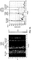
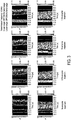
- the echo data will have a specific echo pattern regardless of the existence of the cartilage degeneration, as shown in Figs. 1A and 1B .
- the cartilage interior area normally has the absolute level lower than those of the cartilage surface area and the subchondral bone area which are adjacent to the cartilage interior area.
- a depth position not substantially at “0" is set to an end of the cartilage surface area on the skin surface side (a boundary with the soft tissue area, such as the skin). Then, as the depth is taken deeper, a point where the echo level decreases rapidly below a second level difference threshold is set to a border between the cartilage surface area and the cartilage interior area. As the depth is further taken deeper, a point where the echo level increases rapidly over a third level difference threshold is set to a border between the cartilage interior area and the subchondral bone area. Note that the third level difference threshold for determining the boundary between the cartilage interior area and the subchondral bone area is set lower than the first level difference threshold for determining the cartilage surface area.
- the cartilage surface area, the cartilage interior area, and the subchondral bone area can be classified.
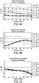
- the above-described method (i) is effective if there is no cartilage degeneration or if it is in an early stage of degeneration. However, if the cartilage degeneration advances, the echo level of the cartilage surface area will decrease and the echo level of the cartilage interior area will increase. Thereby, the boundary may not be clearly distinguished. For this reason, the area classification is performed in this arrangement by using the frequency characteristic for every area as shown in Figs. 4A to 4C .
- the echo level has a different frequency characteristic in each part of the cartilage (i.e., the cartilage surface area, the cartilage interior area, and the subchondral bone area).
- the echo level decreases with an increase of the transmission frequency in the predetermined frequency range (10 MHz to 24 MHz).
- the echo level increases in the predetermined frequency range (10 MHz to 24 MHz) with the increase in the transmission frequency
- the echo data then decreases after it reaches a local maximum value (about 21 MHz).
- the echo level decreases with the increase of the transmission frequency in the predetermined frequency range (10 MHz to 24 MHz).
- the cartilage surface area and the subchondral bone area similarly have characteristics in which the echo level decreases with the increase of the transmission frequency.
- the cartilage interior area exists between the cartilage surface area and the subchondral bone area, the echo data arranged in the depth direction do not overlap with each other.
- each pulse burst signal is transmitted at different transmission frequencies for every PING, and respective echo data are acquired. Then, the plural partial echo data of the plurality of PINGs (at two or more frequencies) for each depth position are read out to acquire the frequency characteristics.
- the pulse burst signal may be a chirp-like pulse burst signal where the frequency of the carrier wave changes within one pulse. If the chirp-like pulse burst signal is used, the echo data of the plurality of frequencies can be acquired only by one transmission, for example.
- the depth position and each area are made associated with each other, and, further, the lapsed time from the transmission timing in each transmission frequency and each area are made associated with each other.
- the pulse burst signal of the specific single frequency set in advance is transmitted sequentially, and echo data is acquired sequentially.
- a classification criterion of each area is stored in a form of the lapsed time for every transmission frequency, it can be determined which area the partial echo data which constitutes the echo data belongs based on the lapsed time.
- the echo area determination module 41 outputs the determined echo data to the analysis data generation module 42.
- the analysis data generation module 42 extracts the classified-by-area echo data of at least the cartilage surface area and the cartilage interior area, and calculates relative ratio data as the analysis data for the cartilage.
- a maximum value of the echo level is calculated based on the partial echo data at two or more depth positions included in the classified-by-area echo data of the cartilage surface area in 1PING, for example.
- the maximum value of the echo level is calculated based on the partial echo data at two or more depth positions included in the classified-by-area echo data of the cartilage interior area in 1PING.
- the relative ratio data for every PING is calculated by calculating a ratio of the maximum value of the echo level of the cartilage surface area and the maximum value of the echo level of the cartilage interior area.
- the maximum value of the echo level is calculated based on the partial echo data group which constitutes the classified-by-area echo data of the cartilage surface area for a predetermined number of PINGs.
- the maximum value of the echo level is calculated based on the partial echo data group which constitutes the classified-by-area echo data of the cartilage interior area for the predetermined number of PINGs.
- a relative ratio data using the echo data for two or more PINGs is calculated by calculating a ratio of the maximum value of the echo data of the cartilage surface area and the maximum value of the echo level of the cartilage interior area.
- the echo data of two or more PINGs may be synchronized and added at a suitable reference, and the maximum value for each area is then calculated. Then, the relative ratio data may be calculated by calculating the ratio of the maximum value for each area.
- an integral value of the echo levels of the partial echo data may be calculated for every area, and the relative ratio data may be calculated based on the integral value.
- the relative ratio may be calculated using a value reflecting the echo level for each area (a median value, a mean value or the like of the two or more echo levels).
- the echo data analyzing module 4 outputs the relative ratio data calculated in this way and the echo data stored in the memory module 40 to the display module 5 as the analysis data.
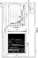
- the display module 5 displays an echo pattern image based on the echo data and a text image of the relative ratio in a display screen.
- Fig. 6 is a diagram showing a form of the display image of this arrangement.
- an echo pattern display window 501 and a relative ratio display window 502 are displayed.
- an echo pattern image which covers two or more PINGs and displays the echo data two-dimensionally is included, where the horizontal axis is set to a depth (time) and the vertical axis is set to a PING number.
- the echo pattern display window 501 also includes an echo level image, where the horizontal axis is set to the depth (time) and the vertical axis is set to the echo level.
- the echo pattern image is displayed so as to be classified by color according to the levels of the partial echo data. Thereby, the user can visually recognize the echo level from each part of the cartilage intuitively.
- an envelope curve is displayed, wherein the average value and the maximum value of the partial echo data of two or more PINGs are calculated at each depth position (position on the time-axis), and the curve envelops the average values and the maximum values sequentially in the depth direction.
- relative ratio display window 502 a numerical value of the calculated relative ratio is displayed. Thereby, the user can visually recognize intuitively, quantitatively and clearly the relative ratio of the echo level of the cartilage surface area and the echo level of the cartilage interior area.
- the information for evaluating the existence of cartilage degeneration can be provided to the user intuitively, quantitatively and clearly.
- the display color of the relative ratio display window 502 may be changed according to the value of the relative ratio data. Thereby, the indication which is further excellent in the visibility according to a cartilage-like object can be performed.
- an ultrasonic bone analyzing device according to a second arrangement is described with reference to the appended drawings.
- the pulse burst signal at single frequency is used and only the frequency band component of the pulse burst signal in the echo signal is used.
- a frequency band component (fundamental frequency band component) of the pulse burst signal in the echo signal and a harmonic component (second harmonic component) are used.
- Fig. 7 is a diagram showing a configuration of an echo signal reception module 3' and an echo data analyzing module 4' of the ultrasonic bone analyzing device of this embodiment.
- an echo signal is inputted into a fundamental wave bandpass filter (BPF) 30A and a second harmonic wave bandpass filter (BPF) 30B.
- the fundamental wave BPF 30A is a bandpass filter having a predetermined frequency band as its pass band, where the fundamental wave component (transmission frequency component of the pulse burst signal) in the echo signal is its center frequency.
- the fundamental wave BPF 30A outputs the fundamental frequency component of the echo signal to the echo data generation module 31A.
- the echo data generation module 31A samples the fundamental frequency component of the echo signal at a sampling interval according to the fundamental frequency to generate echo data where partial echo data are arranged in a time series (i.e., in the depth direction).
- the echo data of the generated fundamental frequency component is outputted to a fundamental frequency component analyzing module 4A of the echo data analyzing module 4'.
- the second harmonic wave BPF 30B is a bandpass filter having a predetermined frequency band width as its pass band, where the second harmonic wave component (second harmonic frequency with respect to the transmission frequency of the pulse burst signal) in the echo signal as its center frequency.
- the second harmonic wave BPF 30B outputs the second harmonic wave frequency component of the echo signal to the echo data generation module 31B.
- the echo data generation module 31B samples the second harmonic wave frequency component of the echo signal at a sampling interval according to the second harmonic wave frequency to generate echo data where partial echo data are arranged in a time series (i.e., in the depth direction).
- the echo data of the generated second harmonic wave frequency component is outputted to a second harmonic wave frequency component analyzing module 4B of the echo data analyzing module 4'.
- the fundamental frequency component analyzing module 4A includes a memory module 40A, an echo area determination module 41A, an analysis data generation module 42A, which is a similar configuration to the echo data analyzing module 4 of the first arrangement described above.
- the analysis data generation module 42A calculates the relative ratio data based on the fundamental wave, and outputs it along with the echo data of the fundamental wave stored in the memory module 40A, collectively as fundamental wave analysis data.
- the second harmonic wave frequency component analyzing module 4B includes the memory module 40A, the echo area determination module 41B, the analysis data generation module 42A, which is a similar configuration to the echo data analyzing module 4 of the first arrangement or the fundamental frequency component analyzing module 4A described above.
- the analysis data generation module 42B calculates the relative ratio data based on the second harmonic wave, and outputs it along with the echo data of the second harmonic wave stored in the memory module 40B, collectively as second harmonic wave analysis data.
- the display module 5 displays an echo pattern image based on the fundamental wave echo data and the second harmonic wave echo data on a display screen using the fundamental wave analysis data and the second harmonic wave analysis data, and displays the relative ratio of the respective frequencies.
- Fig. 8 is a diagram showing a form of a display image of this embodiment. As shown in Fig. 8 , a display screen image 500' has an echo pattern display window 501' and a relative ratio display window 502' which are displayed side-by-side. The echo pattern and the relative ratio data of the fundamental wave are displayed on the upper half of each window, and the echo pattern and the relative ratio data of the second harmonic wave are displayed on the lower half.
- the analysis data according to two or more frequencies can be displayed intuitively, quantitatively and clearly. Thereby, more determination information for the existence of cartilage degeneration can be displayed.
- information for determining whether the frequency setting is suitable can also be provided. For example, in the case of Fig. 8 , at the fundamental frequency, the echo of the cartilage interior area is too low, and the reliability of the relative ratio may become low. However, at the second harmonic wave frequency, the echo level of the cartilage interior area can be obtained at a predetermined level and, thus, it can check that the reliability of the relative ratio is higher than the relative ratio of the fundamental frequency. Using this, the user can refer to the more probable relative ratio of the echo pattern, and can use it to adjust the transmission frequency.
- the generation of the analysis data based on such a second harmonic frequency can be performed based on the pulse burst signal at the single frequency. Therefore, the analysis data containing more information can be generated and displayed without transmitting the pulse burst signal at two or more frequencies.
- the image of the echo level pattern as shown in the first arrangement may also be displayed on the display screen image 500' of this embodiment for every frequency. Thereby, even more and usable information can be displayed.
- the echo data of the fundamental frequency and the echo data of the second harmonic wave frequency are acquired based on the pulse burst signal of the single frequency (fundamental frequency), and the analysis data is generated based on the pattern where echo levels are arranged on the time-axis (in the distance (depth) direction) for every frequency.
- a level ratio of the echo data of respective frequencies corresponding to the same distance position may be calculated, and it may be used for the analysis data.
- the above description of this embodiment does not describe in detail, as for the method of classifying the echo data into the cartilage surface area, the cartilage interior area, and the subchondral bone area, a similar method to the first arrangement may be used.
- the above classification may also be performed using either one of the fundamental wave echo data and the second harmonic wave echo data.
- the analysis data is generated using the pulse burst signal at the single frequency.
- more information to be contained in the analysis data is added using the pulse burst signal at two or more frequencies.
- the ultrasonic bone analyzing device of this embodiment has a similar fundamental block configuration to the ultrasonic bone analyzing device of the first or second arrangement.
- the pulse burst signal of two or more frequencies is transmitted in the ultrasonic bone analyzing device of the first arrangement is illustrated.
- the transmission control module 1 drives the transducer 2 so that the pulse burst signals of two or more of frequencies at predetermined frequency intervals within the user's input from the user interface module 10 or the predetermined frequency band are transmitted sequentially.
- the transmissions of the pulse burst signals are similarly repeated again, while sequentially changing frequency.
- the transducer 2 transmits the pulse burst signal at each frequency, receives the echo signal, and then outputs it to the echo signal reception module 3.
- the echo signal reception module 3 carries out filter processing of each echo signal with the bandpass filter to which the pass band is set with the transmission frequency of the pulse burst signal which corresponds for every echo signal as described above. Then, the echo signal reception module 3 samples the echo signal, which is filter-processed by each frequency band, according to the frequency to generate echo data where partial echo data are arranged in the depth direction.
- the echo data analyzing module 4 acquires the echo data at each frequency, and as described above, using the time changes (depth changes) and the frequency characteristics, it performs the area classification so that at least the cartilage surface area and the cartilage interior area are classified. Then, the echo data analyzing module 4 calculates the relative ratio data by calculating the relative ratio between the maximum value of the echo data of the cartilage surface area and the maximum value of the echo data of the cartilage interior area.
- the echo data analyzing module 4 of this embodiment calculates the frequency characteristics of the echo data of the cartilage interior area as shown in Fig. 9 based on the echo data at each frequency corresponding to the cartilage interior area.
- Fig. 9 is a diagram showing the frequency characteristic of the echo level for the inside of the cartilage. More specifically, for example, the partial echo data group in each echo data, which is classified into the cartilage interior area as described above, is further classified into frequencies. Then, the maximum and the average value of the partial echo data group at each frequency are calculated, and the frequency characteristic is acquired by associating them with the frequency.
- the echo data analyzing module 4 outputs the stored echo data, the relative ratio data, and the frequency characteristic to the display module 5 as analysis data.
- the display module 5 displays an echo pattern image based on the echo data and a text image of the relative ratio on a display screen.
- Fig. 10 is a diagram showing a form of the display image of this embodiment. As shown in Fig. 10 , in the display screen image 500A, an echo pattern display window 501A, a relative ratio display window 502A, and a frequency characteristic display window 503A are displayed. In the echo pattern display window 501A, the echo pattern and the echo level image are displayed similar to the first arrangement. In the relative ratio display window 502, a numerical value of the calculated relative ratio data is displayed. In the frequency characteristic display window 503A, the calculated frequency characteristic is displayed. Although, in Fig.
- the frequency characteristic display window 503A is displayed so as to overlap with the echo pattern display window 501A or the relative ratio display window 502A, they may also be displayed so as not to overlap with each other if the display module is large enough. If in the case where the windows overlap with each other, a user may perform a selection operation by using a pointing device or the like to display a selected window on the forefront side, or change a size of the window.
- the analysis data also including the frequency characteristic which changes with the state of the cartilage interior area can be further displayed, and more information for evaluating the state of the cartilage can be displayed.
- the measurement is made without moving the tip of the transducer while the transducer contacts the skin.
- a user may rotate the rear end to change the transmitting direction of the pulse burst signal to acquire the echo signals over a predetermined area.
- the echo signals may also be acquired while moving the casing itself containing the transducer.
- the echo area determination module 41 with reference to the detected outer skin side end part of the cartilage surface area, may perform an alignment in the depth direction of the partial echo data which constitutes the echo data. Thereby, the influence of the depth difference for the partial echo data for every echo data due to the difference in the transmitting direction of the pulse burst signal can be eliminated, and more accurate analysis data can be generated.
- the number of transducers is one.
- two or more transducers may be arrayed in the casing, beam forming may be carried out, and electronic scanning or the like may be used, to generate the analysis data for a predetermined area.
- two or more transducers may be arrayed in the casing, and a data selection module may be provided.
- the data selection module may evaluate angles of incident of the pulse burst signals to the cartilage surface based on incoming times of echoes from the cartilage surface which the respective transducers receive, and obtain the analysis data based on the echo signals which the angles of incident is substantially 90 degrees.
- the casing of the transducer contacts the skin.
- the transducer may be separated from the skin so that the transducer focuses on the cartilage.
- the alignment in the depth direction of the partial echo data which constitutes the echo data with respect to the outer skin side end part of the cartilage surface area.
- the memory modules 40, 40A, and 40B are provided in the echo data analyzing module 4 and 4'. However, they may be provided in front of the echo signal reception module 3, for example.
- the relative ratio of the echo levels for each area is calculated and it is used for the analysis data.
- a difference value of the echo levels for each area may be calculated, and it may be used for the analysis data.
- it may be other calculated values reflecting a difference of the echo data for each area.
Landscapes
- Health & Medical Sciences (AREA)
- Life Sciences & Earth Sciences (AREA)
- Biomedical Technology (AREA)
- Heart & Thoracic Surgery (AREA)
- Rheumatology (AREA)
- Biophysics (AREA)
- Nuclear Medicine, Radiotherapy & Molecular Imaging (AREA)
- Pathology (AREA)
- Radiology & Medical Imaging (AREA)
- Engineering & Computer Science (AREA)
- Orthopedic Medicine & Surgery (AREA)
- Physics & Mathematics (AREA)
- Medical Informatics (AREA)
- Molecular Biology (AREA)
- Surgery (AREA)
- Animal Behavior & Ethology (AREA)
- General Health & Medical Sciences (AREA)
- Public Health (AREA)
- Veterinary Medicine (AREA)
- Ultra Sonic Daignosis Equipment (AREA)
Claims (8)
- Ultraschallknochenanalysegerät, umfassend:ein Übertragungsmodul (1, 2) zum Übertragen eines Ultraschallsignals bei einer bestimmten Frequenz in das Innere eines lebenden Körpers hinein von einer äußeren Haut des Körpers aus;ein Empfangsmodul (3) zum Empfangen eines Echosignals, das eine Reflexionswelle des übertragenen Ultraschallsignals aus dem Inneren des lebenden Körpers ist; undein Analysemodul (4) zum Generieren von Analysedaten, die bezeichnend sind für einen Zustand eines Knorpels, mittels eines Amplitudenwerts eines aus zwischen einer Knorpeloberfläche und einem subchondralen Knochen erhaltenen Echosignals aus dem Inneren des Knorpels unter den empfangenen Echosignalen,dadurch gekennzeichnet, dass:das Empfangsmodul (3) eingerichtet ist, um ein Echosignal zu empfangen, das zwei oder mehr Frequenzkomponenten aufweist, die die vorbestimmte Frequenz und eine zweite harmonische Frequenz der vorbestimmten Frequenz enthalten, und das Analysemodul (4) eingerichtet ist, um die Analysedaten basierend auf einem Amplitudenwert eines Echosignals aus dem Inneren des Knorpels für jede empfangene Frequenz zu generieren.
- Ultraschallknochenanalysegerät nach Anspruch 1, wobei das Analysemodul (4) eingerichtet ist, um die Analysedaten basierend auf einem Wert zu generieren, der eine Differenz in einem aus einem Amplitudenwert des Echosignals aus dem inneren des Knorpels und einem Amplitudenwert von der Knorpeloberfläche oder dem subchondralen Knochen erhaltenen Echopegel wiederspiegelt.
- Ultraschallknochenanalysegerät nach Anspruch 1 oder 2, wobei das Übertragungsmodul (1, 2) eingerichtet ist, um ein Ultraschallsignal zu übertragen, das zwei oder mehr Frequenzen aufweist, und das Analysemodul (4) eingerichtet ist, um die Analysedaten basierend auf einem Amplitudenwert des Echosignals aus dem inneren des Knorpels für jede empfangene Frequenz zu generieren.
- Ultraschallknochenanalysegerät nach einem der vorherigen Ansprüche, wobei das Analysemodul (4) eingerichtet ist, um das Echosignal von der Knorpeloberfläche, das in dem empfangenen Echosignal enthalten ist, basierend auf dem Amplitudenwert des Echosignals für jede Frequenz zu detektieren.
- Ultraschallknochenanalysegerät nach einem der Ansprüche 1 bis 3, wobei, das Analysemodul (4) eingerichtet ist, um das Echosignal von dem subchondralen Knochen, das in dem empfangenen Echosignal enthalten ist, basierend auf dem Amplitudenwert des Echosignals für jede empfangene Frequenz zu detektieren.
- Ultraschallknochenanalysegerät nach einem der vorherigen Ansprüche, wobei das Übertragungsmodul (1, 2) eingerichtet ist, um ein Gezwitscher (Chirp)-artigesUltraschallsignal als Ultraschallsignal zu übertragen.
- Ultraschallknochenanalysegerät nach einem der vorherigen Ansprüche, wobei das Übertragungsmodul (1, 2) eingerichtet ist die Ultraschallsignale verschiedener Frequenzen zu verschiedenen Zeitpunkten zu übertragen.
- Ultraschallknochenanalysegerät nach einem der vorherigen Ansprüche, wobei das Übertragungsmodul (1, 2) eingerichtet ist, um eine Vielzahl an Ultraschallsignalen zu übertragen; und
wobei das Analysemodul (4) eingerichtet ist Einfallswinkel der Vielzahl an Ultraschallsignalen zu der Knorpeloberfläche basierend auf Empfangszeiten der Echos von der Knorpeloberfläche, die von der Vielzahl an Ultraschallsignalen produziert werden, zu evaluieren und die Analysedaten basierend auf dem Amplitudenwert des Echosignals zu generieren, wessen Einfallswinkel im Wesentlichen 90 Grad beträgt.
Applications Claiming Priority (1)
| Application Number | Priority Date | Filing Date | Title |
|---|---|---|---|
| JP2009201986A JP5377166B2 (ja) | 2009-09-01 | 2009-09-01 | 超音波骨解析装置 |
Publications (2)
| Publication Number | Publication Date |
|---|---|
| EP2289421A1 EP2289421A1 (de) | 2011-03-02 |
| EP2289421B1 true EP2289421B1 (de) | 2017-11-08 |
Family
ID=43304971
Family Applications (1)
| Application Number | Title | Priority Date | Filing Date |
|---|---|---|---|
| EP10174825.9A Not-in-force EP2289421B1 (de) | 2009-09-01 | 2010-09-01 | Ultraschallknochenanalysegerät |
Country Status (3)
| Country | Link |
|---|---|
| US (1) | US9101291B2 (de) |
| EP (1) | EP2289421B1 (de) |
| JP (1) | JP5377166B2 (de) |
Families Citing this family (13)
| Publication number | Priority date | Publication date | Assignee | Title |
|---|---|---|---|---|
| US8444564B2 (en) | 2009-02-02 | 2013-05-21 | Jointvue, Llc | Noninvasive diagnostic system |
| US10512451B2 (en) | 2010-08-02 | 2019-12-24 | Jointvue, Llc | Method and apparatus for three dimensional reconstruction of a joint using ultrasound |
| US20130144135A1 (en) * | 2011-08-02 | 2013-06-06 | Mohamed R. Mahfouz | Method and apparatus for three dimensional reconstruction of a joint using ultrasound |
| JP5691720B2 (ja) * | 2011-03-25 | 2015-04-01 | コニカミノルタ株式会社 | 超音波診断装置 |
| CA2845044C (en) | 2011-08-12 | 2023-03-28 | Jointvue, Llc | 3-d ultrasound imaging device and methods |
| EP2765919B1 (de) | 2011-10-14 | 2024-01-10 | Jointvue, LLC | Echtzeit-3d-ultraschallrekonstruktion des knies und seiner komplikationen für patientenspezifische implantate und 3d-gelenksinjektionen |
| WO2014045925A1 (ja) * | 2012-09-19 | 2014-03-27 | 古野電気株式会社 | 超音波解析装置、超音波解析方法及びプログラム |
| WO2014045924A1 (ja) * | 2012-09-19 | 2014-03-27 | 古野電気株式会社 | 軟組織軟骨境界面検出方法、軟組織軟骨境界面検出装置、および軟組織軟骨境界面検出プログラム |
| CN104837410B (zh) * | 2012-12-28 | 2017-09-22 | 古野电气株式会社 | 软组织软骨边界面检测方法、软组织软骨边界面检测装置 |
| CN105636520B (zh) * | 2013-10-07 | 2018-12-07 | 古野电气株式会社 | 超声波诊断装置以及特征量计算方法 |
| WO2015137131A1 (ja) * | 2014-03-12 | 2015-09-17 | 古野電気株式会社 | 超音波診断装置、及び超音波診断方法 |
| WO2017110361A1 (ja) * | 2015-12-25 | 2017-06-29 | 古野電気株式会社 | 超音波解析装置、超音波解析方法、および超音波解析プログラム |
| JP7107522B2 (ja) * | 2018-06-07 | 2022-07-27 | 古野電気株式会社 | 超音波解析装置、超音波解析方法および超音波解析プログラム |
Family Cites Families (6)
| Publication number | Priority date | Publication date | Assignee | Title |
|---|---|---|---|---|
| US4771792A (en) * | 1985-02-19 | 1988-09-20 | Seale Joseph B | Non-invasive determination of mechanical characteristics in the body |
| IT1268599B1 (it) * | 1994-01-14 | 1997-03-06 | Igea Srl | Sistema di misura ad ultrasuoni per la rilevazione della densita' e struttura ossea. |
| JP2002345821A (ja) | 2001-05-29 | 2002-12-03 | Koji Hattori | 関節腔内の超音波解析システム |
| WO2003009762A1 (en) | 2001-07-24 | 2003-02-06 | Sunlight Medical, Ltd. | Joint analysis using ultrasound |
| JP4603323B2 (ja) * | 2003-09-30 | 2010-12-22 | 富士フイルム株式会社 | 超音波診断装置 |
| JP4911540B2 (ja) * | 2007-03-05 | 2012-04-04 | 国立大学法人山口大学 | 超音波診断装置 |
-
2009
- 2009-09-01 JP JP2009201986A patent/JP5377166B2/ja not_active Expired - Fee Related
-
2010
- 2010-08-31 US US12/872,880 patent/US9101291B2/en active Active
- 2010-09-01 EP EP10174825.9A patent/EP2289421B1/de not_active Not-in-force
Also Published As
| Publication number | Publication date |
|---|---|
| US9101291B2 (en) | 2015-08-11 |
| JP2011050555A (ja) | 2011-03-17 |
| EP2289421A1 (de) | 2011-03-02 |
| JP5377166B2 (ja) | 2013-12-25 |
| US20110054313A1 (en) | 2011-03-03 |
Similar Documents
| Publication | Publication Date | Title |
|---|---|---|
| US9101291B2 (en) | Ultrasonic bone analysis with harmonic and amplitude of the frequencies from cartilage to determine the relative ratio of integral amplitude values | |
| US20240008841A1 (en) | Ultrasound diagnostic system, ultrasound image generation apparatus, and ultrasound image generation method | |
| CN101933817B (zh) | 超声波诊断装置及诊断参数测量控制方法 | |
| EP2241260B1 (de) | Verfahren und Vorrichtung zur Messung der Schallgeschwindigkeit | |
| EP3040033A1 (de) | Diagnostische ultraschallvorrichtung und elastizitätsbeurteilungsverfahren | |
| WO2008036513A2 (en) | Ultrasonic method and apparatus for assessment of bone | |
| JPH1133024A (ja) | 超音波ドプラ診断装置 | |
| CN112075955B (zh) | 粘弹性介质超声波参数测量方法与装置 | |
| EP2033579A1 (de) | Diagnostisches Ultraschallgerät | |
| EP2454997B1 (de) | Verfahren, Vorrichtung und Programm zur Knorpelanalyse mit Ultraschallwellen | |
| JPWO1998057581A1 (ja) | 連続波送受波型超音波撮像装置及び超音波プローブ | |
| WO1998057581A1 (fr) | Dispositif emetteur-recepteur a ondes entretenues d'imagerie par ultrasons et sonde a ultrasons | |
| JP6134323B2 (ja) | 厚み測定装置及び厚み測定方法 | |
| CN104837410A (zh) | 软组织软骨边界面检测方法、软组织软骨边界面检测装置及软组织软骨边界面检测程序 | |
| CN107427281B (zh) | 超声波诊断装置 | |
| JP4940048B2 (ja) | 超音波撮像装置 | |
| CN108852416B (zh) | 一种剪切波传播速度的确定方法及装置 | |
| US20060173337A1 (en) | Intravascular ultrasound probing device | |
| CN104083143B (zh) | 自动识别图像中有效与无效区域的内窥oct系统 | |
| WO2010068450A1 (en) | System and method for analyzing carpal tunnel using ultrasound imaging | |
| CN107106142B (zh) | 超声波体组织检测装置与方法、以及存储介质 | |
| JP7238164B2 (ja) | 超音波観測装置、超音波観測システム、超音波観測方法、超音波観測プログラム、及び超音波内視鏡システム | |
| HK40036819A (en) | Method and device for measuring an ultrasound parameter of a viscoelastic medium | |
| JP4050707B2 (ja) | 超音波計測装置 | |
| CN116919467A (zh) | 一种超声波骨密度检测系统的检测方法 |
Legal Events
| Date | Code | Title | Description |
|---|---|---|---|
| PUAI | Public reference made under article 153(3) epc to a published international application that has entered the european phase |
Free format text: ORIGINAL CODE: 0009012 |
|
| AK | Designated contracting states |
Kind code of ref document: A1 Designated state(s): AL AT BE BG CH CY CZ DE DK EE ES FI FR GB GR HR HU IE IS IT LI LT LU LV MC MK MT NL NO PL PT RO SE SI SK SM TR |
|
| AX | Request for extension of the european patent |
Extension state: BA ME RS |
|
| 17P | Request for examination filed |
Effective date: 20110801 |
|
| 17Q | First examination report despatched |
Effective date: 20140625 |
|
| GRAP | Despatch of communication of intention to grant a patent |
Free format text: ORIGINAL CODE: EPIDOSNIGR1 |
|
| GRAJ | Information related to disapproval of communication of intention to grant by the applicant or resumption of examination proceedings by the epo deleted |
Free format text: ORIGINAL CODE: EPIDOSDIGR1 |
|
| GRAP | Despatch of communication of intention to grant a patent |
Free format text: ORIGINAL CODE: EPIDOSNIGR1 |
|
| INTG | Intention to grant announced |
Effective date: 20160926 |
|
| RAP1 | Party data changed (applicant data changed or rights of an application transferred) |
Owner name: FURUNO ELECTRIC COMPANY, LIMITED |
|
| INTG | Intention to grant announced |
Effective date: 20161007 |
|
| STAA | Information on the status of an ep patent application or granted ep patent |
Free format text: STATUS: GRANT OF PATENT IS INTENDED |
|
| GRAJ | Information related to disapproval of communication of intention to grant by the applicant or resumption of examination proceedings by the epo deleted |
Free format text: ORIGINAL CODE: EPIDOSDIGR1 |
|
| GRAP | Despatch of communication of intention to grant a patent |
Free format text: ORIGINAL CODE: EPIDOSNIGR1 |
|
| INTG | Intention to grant announced |
Effective date: 20170411 |
|
| GRAS | Grant fee paid |
Free format text: ORIGINAL CODE: EPIDOSNIGR3 |
|
| GRAA | (expected) grant |
Free format text: ORIGINAL CODE: 0009210 |
|
| STAA | Information on the status of an ep patent application or granted ep patent |
Free format text: STATUS: THE PATENT HAS BEEN GRANTED |
|
| AK | Designated contracting states |
Kind code of ref document: B1 Designated state(s): AL AT BE BG CH CY CZ DE DK EE ES FI FR GB GR HR HU IE IS IT LI LT LU LV MC MK MT NL NO PL PT RO SE SI SK SM TR |
|
| REG | Reference to a national code |
Ref country code: GB Ref legal event code: FG4D |
|
| REG | Reference to a national code |
Ref country code: CH Ref legal event code: EP Ref country code: AT Ref legal event code: REF Ref document number: 943386 Country of ref document: AT Kind code of ref document: T Effective date: 20171115 |
|
| REG | Reference to a national code |
Ref country code: IE Ref legal event code: FG4D |
|
| REG | Reference to a national code |
Ref country code: DE Ref legal event code: R096 Ref document number: 602010046479 Country of ref document: DE |
|
| REG | Reference to a national code |
Ref country code: NL Ref legal event code: MP Effective date: 20171108 |
|
| REG | Reference to a national code |
Ref country code: LT Ref legal event code: MG4D |
|
| REG | Reference to a national code |
Ref country code: AT Ref legal event code: MK05 Ref document number: 943386 Country of ref document: AT Kind code of ref document: T Effective date: 20171108 |
|
| PG25 | Lapsed in a contracting state [announced via postgrant information from national office to epo] |
Ref country code: NL Free format text: LAPSE BECAUSE OF FAILURE TO SUBMIT A TRANSLATION OF THE DESCRIPTION OR TO PAY THE FEE WITHIN THE PRESCRIBED TIME-LIMIT Effective date: 20171108 Ref country code: SE Free format text: LAPSE BECAUSE OF FAILURE TO SUBMIT A TRANSLATION OF THE DESCRIPTION OR TO PAY THE FEE WITHIN THE PRESCRIBED TIME-LIMIT Effective date: 20171108 Ref country code: NO Free format text: LAPSE BECAUSE OF FAILURE TO SUBMIT A TRANSLATION OF THE DESCRIPTION OR TO PAY THE FEE WITHIN THE PRESCRIBED TIME-LIMIT Effective date: 20180208 Ref country code: FI Free format text: LAPSE BECAUSE OF FAILURE TO SUBMIT A TRANSLATION OF THE DESCRIPTION OR TO PAY THE FEE WITHIN THE PRESCRIBED TIME-LIMIT Effective date: 20171108 Ref country code: LT Free format text: LAPSE BECAUSE OF FAILURE TO SUBMIT A TRANSLATION OF THE DESCRIPTION OR TO PAY THE FEE WITHIN THE PRESCRIBED TIME-LIMIT Effective date: 20171108 Ref country code: ES Free format text: LAPSE BECAUSE OF FAILURE TO SUBMIT A TRANSLATION OF THE DESCRIPTION OR TO PAY THE FEE WITHIN THE PRESCRIBED TIME-LIMIT Effective date: 20171108 |
|
| PG25 | Lapsed in a contracting state [announced via postgrant information from national office to epo] |
Ref country code: BG Free format text: LAPSE BECAUSE OF FAILURE TO SUBMIT A TRANSLATION OF THE DESCRIPTION OR TO PAY THE FEE WITHIN THE PRESCRIBED TIME-LIMIT Effective date: 20180208 Ref country code: GR Free format text: LAPSE BECAUSE OF FAILURE TO SUBMIT A TRANSLATION OF THE DESCRIPTION OR TO PAY THE FEE WITHIN THE PRESCRIBED TIME-LIMIT Effective date: 20180209 Ref country code: HR Free format text: LAPSE BECAUSE OF FAILURE TO SUBMIT A TRANSLATION OF THE DESCRIPTION OR TO PAY THE FEE WITHIN THE PRESCRIBED TIME-LIMIT Effective date: 20171108 Ref country code: AT Free format text: LAPSE BECAUSE OF FAILURE TO SUBMIT A TRANSLATION OF THE DESCRIPTION OR TO PAY THE FEE WITHIN THE PRESCRIBED TIME-LIMIT Effective date: 20171108 Ref country code: LV Free format text: LAPSE BECAUSE OF FAILURE TO SUBMIT A TRANSLATION OF THE DESCRIPTION OR TO PAY THE FEE WITHIN THE PRESCRIBED TIME-LIMIT Effective date: 20171108 Ref country code: IS Free format text: LAPSE BECAUSE OF FAILURE TO SUBMIT A TRANSLATION OF THE DESCRIPTION OR TO PAY THE FEE WITHIN THE PRESCRIBED TIME-LIMIT Effective date: 20180308 |
|
| PG25 | Lapsed in a contracting state [announced via postgrant information from national office to epo] |
Ref country code: SK Free format text: LAPSE BECAUSE OF FAILURE TO SUBMIT A TRANSLATION OF THE DESCRIPTION OR TO PAY THE FEE WITHIN THE PRESCRIBED TIME-LIMIT Effective date: 20171108 Ref country code: CZ Free format text: LAPSE BECAUSE OF FAILURE TO SUBMIT A TRANSLATION OF THE DESCRIPTION OR TO PAY THE FEE WITHIN THE PRESCRIBED TIME-LIMIT Effective date: 20171108 Ref country code: CY Free format text: LAPSE BECAUSE OF FAILURE TO SUBMIT A TRANSLATION OF THE DESCRIPTION OR TO PAY THE FEE WITHIN THE PRESCRIBED TIME-LIMIT Effective date: 20171108 Ref country code: DK Free format text: LAPSE BECAUSE OF FAILURE TO SUBMIT A TRANSLATION OF THE DESCRIPTION OR TO PAY THE FEE WITHIN THE PRESCRIBED TIME-LIMIT Effective date: 20171108 Ref country code: EE Free format text: LAPSE BECAUSE OF FAILURE TO SUBMIT A TRANSLATION OF THE DESCRIPTION OR TO PAY THE FEE WITHIN THE PRESCRIBED TIME-LIMIT Effective date: 20171108 |
|
| REG | Reference to a national code |
Ref country code: DE Ref legal event code: R097 Ref document number: 602010046479 Country of ref document: DE |
|
| PG25 | Lapsed in a contracting state [announced via postgrant information from national office to epo] |
Ref country code: PL Free format text: LAPSE BECAUSE OF FAILURE TO SUBMIT A TRANSLATION OF THE DESCRIPTION OR TO PAY THE FEE WITHIN THE PRESCRIBED TIME-LIMIT Effective date: 20171108 Ref country code: RO Free format text: LAPSE BECAUSE OF FAILURE TO SUBMIT A TRANSLATION OF THE DESCRIPTION OR TO PAY THE FEE WITHIN THE PRESCRIBED TIME-LIMIT Effective date: 20171108 Ref country code: IT Free format text: LAPSE BECAUSE OF FAILURE TO SUBMIT A TRANSLATION OF THE DESCRIPTION OR TO PAY THE FEE WITHIN THE PRESCRIBED TIME-LIMIT Effective date: 20171108 Ref country code: SM Free format text: LAPSE BECAUSE OF FAILURE TO SUBMIT A TRANSLATION OF THE DESCRIPTION OR TO PAY THE FEE WITHIN THE PRESCRIBED TIME-LIMIT Effective date: 20171108 |
|
| PLBE | No opposition filed within time limit |
Free format text: ORIGINAL CODE: 0009261 |
|
| STAA | Information on the status of an ep patent application or granted ep patent |
Free format text: STATUS: NO OPPOSITION FILED WITHIN TIME LIMIT |
|
| 26N | No opposition filed |
Effective date: 20180809 |
|
| PG25 | Lapsed in a contracting state [announced via postgrant information from national office to epo] |
Ref country code: SI Free format text: LAPSE BECAUSE OF FAILURE TO SUBMIT A TRANSLATION OF THE DESCRIPTION OR TO PAY THE FEE WITHIN THE PRESCRIBED TIME-LIMIT Effective date: 20171108 |
|
| PG25 | Lapsed in a contracting state [announced via postgrant information from national office to epo] |
Ref country code: MC Free format text: LAPSE BECAUSE OF FAILURE TO SUBMIT A TRANSLATION OF THE DESCRIPTION OR TO PAY THE FEE WITHIN THE PRESCRIBED TIME-LIMIT Effective date: 20171108 |
|
| REG | Reference to a national code |
Ref country code: CH Ref legal event code: PL |
|
| GBPC | Gb: european patent ceased through non-payment of renewal fee |
Effective date: 20180901 |
|
| REG | Reference to a national code |
Ref country code: BE Ref legal event code: MM Effective date: 20180930 |
|
| REG | Reference to a national code |
Ref country code: IE Ref legal event code: MM4A |
|
| PG25 | Lapsed in a contracting state [announced via postgrant information from national office to epo] |
Ref country code: LU Free format text: LAPSE BECAUSE OF NON-PAYMENT OF DUE FEES Effective date: 20180901 |
|
| PG25 | Lapsed in a contracting state [announced via postgrant information from national office to epo] |
Ref country code: IE Free format text: LAPSE BECAUSE OF NON-PAYMENT OF DUE FEES Effective date: 20180901 |
|
| PG25 | Lapsed in a contracting state [announced via postgrant information from national office to epo] |
Ref country code: LI Free format text: LAPSE BECAUSE OF NON-PAYMENT OF DUE FEES Effective date: 20180930 Ref country code: CH Free format text: LAPSE BECAUSE OF NON-PAYMENT OF DUE FEES Effective date: 20180930 Ref country code: BE Free format text: LAPSE BECAUSE OF NON-PAYMENT OF DUE FEES Effective date: 20180930 Ref country code: FR Free format text: LAPSE BECAUSE OF NON-PAYMENT OF DUE FEES Effective date: 20180930 |
|
| PG25 | Lapsed in a contracting state [announced via postgrant information from national office to epo] |
Ref country code: GB Free format text: LAPSE BECAUSE OF NON-PAYMENT OF DUE FEES Effective date: 20180901 |
|
| PG25 | Lapsed in a contracting state [announced via postgrant information from national office to epo] |
Ref country code: MT Free format text: LAPSE BECAUSE OF NON-PAYMENT OF DUE FEES Effective date: 20180901 |
|
| PG25 | Lapsed in a contracting state [announced via postgrant information from national office to epo] |
Ref country code: TR Free format text: LAPSE BECAUSE OF FAILURE TO SUBMIT A TRANSLATION OF THE DESCRIPTION OR TO PAY THE FEE WITHIN THE PRESCRIBED TIME-LIMIT Effective date: 20171108 |
|
| PG25 | Lapsed in a contracting state [announced via postgrant information from national office to epo] |
Ref country code: HU Free format text: LAPSE BECAUSE OF FAILURE TO SUBMIT A TRANSLATION OF THE DESCRIPTION OR TO PAY THE FEE WITHIN THE PRESCRIBED TIME-LIMIT; INVALID AB INITIO Effective date: 20100901 Ref country code: PT Free format text: LAPSE BECAUSE OF FAILURE TO SUBMIT A TRANSLATION OF THE DESCRIPTION OR TO PAY THE FEE WITHIN THE PRESCRIBED TIME-LIMIT Effective date: 20171108 |
|
| PG25 | Lapsed in a contracting state [announced via postgrant information from national office to epo] |
Ref country code: MK Free format text: LAPSE BECAUSE OF NON-PAYMENT OF DUE FEES Effective date: 20171108 |
|
| PG25 | Lapsed in a contracting state [announced via postgrant information from national office to epo] |
Ref country code: AL Free format text: LAPSE BECAUSE OF FAILURE TO SUBMIT A TRANSLATION OF THE DESCRIPTION OR TO PAY THE FEE WITHIN THE PRESCRIBED TIME-LIMIT Effective date: 20171108 |
|
| P01 | Opt-out of the competence of the unified patent court (upc) registered |
Effective date: 20230523 |
|
| PGFP | Annual fee paid to national office [announced via postgrant information from national office to epo] |
Ref country code: DE Payment date: 20230802 Year of fee payment: 14 |
|
| REG | Reference to a national code |
Ref country code: DE Ref legal event code: R119 Ref document number: 602010046479 Country of ref document: DE |
|
| PG25 | Lapsed in a contracting state [announced via postgrant information from national office to epo] |
Ref country code: DE Free format text: LAPSE BECAUSE OF NON-PAYMENT OF DUE FEES Effective date: 20250401 |