EP2288786B1 - Gas compression system - Google Patents
Gas compression system Download PDFInfo
- Publication number
- EP2288786B1 EP2288786B1 EP09734652.2A EP09734652A EP2288786B1 EP 2288786 B1 EP2288786 B1 EP 2288786B1 EP 09734652 A EP09734652 A EP 09734652A EP 2288786 B1 EP2288786 B1 EP 2288786B1
- Authority
- EP
- European Patent Office
- Prior art keywords
- gas
- liquid
- flow
- compressor
- pipe
- Prior art date
- Legal status (The legal status is an assumption and is not a legal conclusion. Google has not performed a legal analysis and makes no representation as to the accuracy of the status listed.)
- Active
Links
Images

Classifications
-
- E—FIXED CONSTRUCTIONS
- E21—EARTH OR ROCK DRILLING; MINING
- E21B—EARTH OR ROCK DRILLING; OBTAINING OIL, GAS, WATER, SOLUBLE OR MELTABLE MATERIALS OR A SLURRY OF MINERALS FROM WELLS
- E21B43/00—Methods or apparatus for obtaining oil, gas, water, soluble or meltable materials or a slurry of minerals from wells
- E21B43/01—Methods or apparatus for obtaining oil, gas, water, soluble or meltable materials or a slurry of minerals from wells specially adapted for obtaining from underwater installations
-
- E—FIXED CONSTRUCTIONS
- E21—EARTH OR ROCK DRILLING; MINING
- E21B—EARTH OR ROCK DRILLING; OBTAINING OIL, GAS, WATER, SOLUBLE OR MELTABLE MATERIALS OR A SLURRY OF MINERALS FROM WELLS
- E21B43/00—Methods or apparatus for obtaining oil, gas, water, soluble or meltable materials or a slurry of minerals from wells
- E21B43/34—Arrangements for separating materials produced by the well
- E21B43/35—Arrangements for separating materials produced by the well specially adapted for separating solids
-
- E—FIXED CONSTRUCTIONS
- E21—EARTH OR ROCK DRILLING; MINING
- E21B—EARTH OR ROCK DRILLING; OBTAINING OIL, GAS, WATER, SOLUBLE OR MELTABLE MATERIALS OR A SLURRY OF MINERALS FROM WELLS
- E21B43/00—Methods or apparatus for obtaining oil, gas, water, soluble or meltable materials or a slurry of minerals from wells
- E21B43/34—Arrangements for separating materials produced by the well
- E21B43/36—Underwater separating arrangements
-
- F—MECHANICAL ENGINEERING; LIGHTING; HEATING; WEAPONS; BLASTING
- F04—POSITIVE - DISPLACEMENT MACHINES FOR LIQUIDS; PUMPS FOR LIQUIDS OR ELASTIC FLUIDS
- F04D—NON-POSITIVE-DISPLACEMENT PUMPS
- F04D1/00—Radial-flow pumps, e.g. centrifugal pumps; Helico-centrifugal pumps
-
- F—MECHANICAL ENGINEERING; LIGHTING; HEATING; WEAPONS; BLASTING
- F04—POSITIVE - DISPLACEMENT MACHINES FOR LIQUIDS; PUMPS FOR LIQUIDS OR ELASTIC FLUIDS
- F04D—NON-POSITIVE-DISPLACEMENT PUMPS
- F04D13/00—Pumping installations or systems
- F04D13/02—Units comprising pumps and their driving means
- F04D13/06—Units comprising pumps and their driving means the pump being electrically driven
-
- F—MECHANICAL ENGINEERING; LIGHTING; HEATING; WEAPONS; BLASTING
- F04—POSITIVE - DISPLACEMENT MACHINES FOR LIQUIDS; PUMPS FOR LIQUIDS OR ELASTIC FLUIDS
- F04D—NON-POSITIVE-DISPLACEMENT PUMPS
- F04D13/00—Pumping installations or systems
- F04D13/12—Combinations of two or more pumps
-
- F—MECHANICAL ENGINEERING; LIGHTING; HEATING; WEAPONS; BLASTING
- F04—POSITIVE - DISPLACEMENT MACHINES FOR LIQUIDS; PUMPS FOR LIQUIDS OR ELASTIC FLUIDS
- F04D—NON-POSITIVE-DISPLACEMENT PUMPS
- F04D17/00—Radial-flow pumps, e.g. centrifugal pumps; Helico-centrifugal pumps
- F04D17/08—Centrifugal pumps
-
- F—MECHANICAL ENGINEERING; LIGHTING; HEATING; WEAPONS; BLASTING
- F04—POSITIVE - DISPLACEMENT MACHINES FOR LIQUIDS; PUMPS FOR LIQUIDS OR ELASTIC FLUIDS
- F04D—NON-POSITIVE-DISPLACEMENT PUMPS
- F04D25/00—Pumping installations or systems
- F04D25/02—Units comprising pumps and their driving means
- F04D25/06—Units comprising pumps and their driving means the pump being electrically driven
- F04D25/0686—Units comprising pumps and their driving means the pump being electrically driven specially adapted for submerged use
-
- F—MECHANICAL ENGINEERING; LIGHTING; HEATING; WEAPONS; BLASTING
- F04—POSITIVE - DISPLACEMENT MACHINES FOR LIQUIDS; PUMPS FOR LIQUIDS OR ELASTIC FLUIDS
- F04D—NON-POSITIVE-DISPLACEMENT PUMPS
- F04D25/00—Pumping installations or systems
- F04D25/16—Combinations of two or more pumps ; Producing two or more separate gas flows
-
- F—MECHANICAL ENGINEERING; LIGHTING; HEATING; WEAPONS; BLASTING
- F04—POSITIVE - DISPLACEMENT MACHINES FOR LIQUIDS; PUMPS FOR LIQUIDS OR ELASTIC FLUIDS
- F04D—NON-POSITIVE-DISPLACEMENT PUMPS
- F04D29/00—Details, component parts, or accessories
- F04D29/04—Shafts or bearings, or assemblies thereof
- F04D29/046—Bearings
-
- F—MECHANICAL ENGINEERING; LIGHTING; HEATING; WEAPONS; BLASTING
- F04—POSITIVE - DISPLACEMENT MACHINES FOR LIQUIDS; PUMPS FOR LIQUIDS OR ELASTIC FLUIDS
- F04D—NON-POSITIVE-DISPLACEMENT PUMPS
- F04D29/00—Details, component parts, or accessories
- F04D29/05—Shafts or bearings, or assemblies thereof, specially adapted for elastic fluid pumps
-
- F—MECHANICAL ENGINEERING; LIGHTING; HEATING; WEAPONS; BLASTING
- F04—POSITIVE - DISPLACEMENT MACHINES FOR LIQUIDS; PUMPS FOR LIQUIDS OR ELASTIC FLUIDS
- F04D—NON-POSITIVE-DISPLACEMENT PUMPS
- F04D29/00—Details, component parts, or accessories
- F04D29/18—Rotors
- F04D29/22—Rotors specially for centrifugal pumps
-
- F—MECHANICAL ENGINEERING; LIGHTING; HEATING; WEAPONS; BLASTING
- F04—POSITIVE - DISPLACEMENT MACHINES FOR LIQUIDS; PUMPS FOR LIQUIDS OR ELASTIC FLUIDS
- F04D—NON-POSITIVE-DISPLACEMENT PUMPS
- F04D29/00—Details, component parts, or accessories
- F04D29/26—Rotors specially for elastic fluids
- F04D29/28—Rotors specially for elastic fluids for centrifugal or helico-centrifugal pumps for radial-flow or helico-centrifugal pumps
- F04D29/284—Rotors specially for elastic fluids for centrifugal or helico-centrifugal pumps for radial-flow or helico-centrifugal pumps for compressors
-
- F—MECHANICAL ENGINEERING; LIGHTING; HEATING; WEAPONS; BLASTING
- F04—POSITIVE - DISPLACEMENT MACHINES FOR LIQUIDS; PUMPS FOR LIQUIDS OR ELASTIC FLUIDS
- F04D—NON-POSITIVE-DISPLACEMENT PUMPS
- F04D29/00—Details, component parts, or accessories
- F04D29/40—Casings; Connections of working fluid
-
- F—MECHANICAL ENGINEERING; LIGHTING; HEATING; WEAPONS; BLASTING
- F04—POSITIVE - DISPLACEMENT MACHINES FOR LIQUIDS; PUMPS FOR LIQUIDS OR ELASTIC FLUIDS
- F04D—NON-POSITIVE-DISPLACEMENT PUMPS
- F04D29/00—Details, component parts, or accessories
- F04D29/58—Cooling; Heating; Diminishing heat transfer
-
- F—MECHANICAL ENGINEERING; LIGHTING; HEATING; WEAPONS; BLASTING
- F04—POSITIVE - DISPLACEMENT MACHINES FOR LIQUIDS; PUMPS FOR LIQUIDS OR ELASTIC FLUIDS
- F04D—NON-POSITIVE-DISPLACEMENT PUMPS
- F04D29/00—Details, component parts, or accessories
- F04D29/70—Suction grids; Strainers; Dust separation; Cleaning
-
- F—MECHANICAL ENGINEERING; LIGHTING; HEATING; WEAPONS; BLASTING
- F04—POSITIVE - DISPLACEMENT MACHINES FOR LIQUIDS; PUMPS FOR LIQUIDS OR ELASTIC FLUIDS
- F04D—NON-POSITIVE-DISPLACEMENT PUMPS
- F04D31/00—Pumping liquids and elastic fluids at the same time
-
- F—MECHANICAL ENGINEERING; LIGHTING; HEATING; WEAPONS; BLASTING
- F04—POSITIVE - DISPLACEMENT MACHINES FOR LIQUIDS; PUMPS FOR LIQUIDS OR ELASTIC FLUIDS
- F04F—PUMPING OF FLUID BY DIRECT CONTACT OF ANOTHER FLUID OR BY USING INERTIA OF FLUID TO BE PUMPED; SIPHONS
- F04F5/00—Jet pumps, i.e. devices in which flow is induced by pressure drop caused by velocity of another fluid flow
- F04F5/02—Jet pumps, i.e. devices in which flow is induced by pressure drop caused by velocity of another fluid flow the inducing fluid being liquid
- F04F5/04—Jet pumps, i.e. devices in which flow is induced by pressure drop caused by velocity of another fluid flow the inducing fluid being liquid displacing elastic fluids
-
- Y—GENERAL TAGGING OF NEW TECHNOLOGICAL DEVELOPMENTS; GENERAL TAGGING OF CROSS-SECTIONAL TECHNOLOGIES SPANNING OVER SEVERAL SECTIONS OF THE IPC; TECHNICAL SUBJECTS COVERED BY FORMER USPC CROSS-REFERENCE ART COLLECTIONS [XRACs] AND DIGESTS
- Y10—TECHNICAL SUBJECTS COVERED BY FORMER USPC
- Y10T—TECHNICAL SUBJECTS COVERED BY FORMER US CLASSIFICATION
- Y10T137/00—Fluid handling
- Y10T137/1842—Ambient condition change responsive
- Y10T137/2036—Underwater
-
- Y—GENERAL TAGGING OF NEW TECHNOLOGICAL DEVELOPMENTS; GENERAL TAGGING OF CROSS-SECTIONAL TECHNOLOGIES SPANNING OVER SEVERAL SECTIONS OF THE IPC; TECHNICAL SUBJECTS COVERED BY FORMER USPC CROSS-REFERENCE ART COLLECTIONS [XRACs] AND DIGESTS
- Y10—TECHNICAL SUBJECTS COVERED BY FORMER USPC
- Y10T—TECHNICAL SUBJECTS COVERED BY FORMER US CLASSIFICATION
- Y10T137/00—Fluid handling
- Y10T137/2496—Self-proportioning or correlating systems
- Y10T137/2559—Self-controlled branched flow systems
- Y10T137/2562—Dividing and recombining
-
- Y—GENERAL TAGGING OF NEW TECHNOLOGICAL DEVELOPMENTS; GENERAL TAGGING OF CROSS-SECTIONAL TECHNOLOGIES SPANNING OVER SEVERAL SECTIONS OF THE IPC; TECHNICAL SUBJECTS COVERED BY FORMER USPC CROSS-REFERENCE ART COLLECTIONS [XRACs] AND DIGESTS
- Y10—TECHNICAL SUBJECTS COVERED BY FORMER USPC
- Y10T—TECHNICAL SUBJECTS COVERED BY FORMER US CLASSIFICATION
- Y10T137/00—Fluid handling
- Y10T137/2931—Diverse fluid containing pressure systems
- Y10T137/3003—Fluid separating traps or vents
-
- Y—GENERAL TAGGING OF NEW TECHNOLOGICAL DEVELOPMENTS; GENERAL TAGGING OF CROSS-SECTIONAL TECHNOLOGIES SPANNING OVER SEVERAL SECTIONS OF THE IPC; TECHNICAL SUBJECTS COVERED BY FORMER USPC CROSS-REFERENCE ART COLLECTIONS [XRACs] AND DIGESTS
- Y10—TECHNICAL SUBJECTS COVERED BY FORMER USPC
- Y10T—TECHNICAL SUBJECTS COVERED BY FORMER US CLASSIFICATION
- Y10T137/00—Fluid handling
- Y10T137/8593—Systems
- Y10T137/87265—Dividing into parallel flow paths with recombining
Definitions
- the present invention relates to a system for wet gas compression, comprising a compact flow conditioner, a multi-phase flow meter and a downstream multi-phase compressor of the centrifugal compressor type, designed to be installed below sea level in the vicinity of a well head, the flow conditioner being designed to be supplied with multi-phase flow of hydrocarbons from a sub sea well, convey and preferably avoid accumulation or remove as much sand from said multi phase flow as possible.
- GB 2 264 147 discloses a booster arrangement for boosting multi-phase fluids from a reservoir in a formation to a processing plant, where the boosting arrangement is placed in a flow line between the reservoir and the processing plant.
- the arrangement comprises a separation vessel for separation of liquid/gas, where said separation vessel has an inlet for supplying a mixture of oil and gas prior to further separate transport of the gas and the liquid.
- the boosting arrangement comprises a motor driven pump, designed to lift the liquid fraction out of the scrubber and further to a jet pump, while the separated gas is allowed to flow through a separate pipe to said jet pump. From the jet pump, the mixed gas and liquid is then compressed to a processing plant at a substantially higher pressure than the pressure at the inlet to the separation vessel.
- US 2001/005483 discloses a system for mixing and compressing a multi-phase fluid including a soluble gas and a solvent.
- the gas and solvent are mixed and compressed using a pumping device comprising a series of impellers and diffusers.
- the flow conditioner is designed for receiving a multi-phase flow of mainly hydrocarbons from one or more sub sea wells, to transport and secure an even flow of gas and liquid to the wet gas compressor and preferably to avoid accumulation or remove as much sand as possible from said multi-phase flow.
- the presence of a well flow liquid through the entire compressor shall prevent formation of deposits, increase the pressure conditions in the machine, secure cooling of the gas during the compression stage and reduce erosion, since the velocity energy from possible particles is absorbed by the liquid film wetting the entire surface of the compression circuit.
- An object of the present invention is to be able to handle large volumes of gas and accompanying smaller volumes of liquid, at partly substantial pressure differences between said two fluids.
- Another object of the invention is to increase available power of the system by more than tens of megawatts.
- a still further object of the invention is to reduce the number of critical components in the process system on the sea bed, and to make critical components more robust by introducing new technological elements.
- Such critical components or back-up functions are:
- a still further object of the invention is to improve the existing systems.
- the compressor remains a vital part of the system, handling the pressure increase in the gas as its primary function.
- the compressor is designed to be robust with respect to gas/liquid flow conditioning, redundancy, several levels of barriers against failure and simplified auxiliary systems.
- the compressor is installed in the vicinity of the sub sea production wells and shall deliver output to a single exit pipeline.
- a gas compression system comprising a compact flow conditioner, intended to be placed below sea level in close vicinity to a well head, said flow conditioner being intended to receive a multi-phase flow of hydrocarbons through a supply pipe from a sub sea well for further transport of such hydrocarbons to a remote multi-phase receiving plant, wherein the gas and the liquid are separated in the flow conditioner, characterised in that the separated gas and liquid are re-assembled and enter a multi-phase meter prior to boosting by means of a combined multi-phase pump and compressor unit functioning on the centrifugal principle, wherein the combined multi-phase pump and compressor unit is an integrated unit used for transporting liquid and gas from the flow conditioner to the remote multi-phase receiving plant, wherein a regulating valve is opened to recirculate gas from downstream of the unit to upstream of the unit via a re-circulation loop responsive to detection by the multi-phase flow meter of an unusually high level of liquid or an unstable pulsating supply of fluid, and wherein said flow
- the pump and compressor unit comprises one or more impellers functioning on the centrifugal principle and will in the following be denoted as the wet gas compressor.
- Such unit shall be in position to pressurize a well flow comprising of gas, liquid and particles.
- the wet gas compressor may be powered by a turbine, but is preferably powered by an electromotor integrated within the same pressure casing as the compressor, where process gas or the gas from the well flow is used for cooling the electromotor and the bearings.
- the hot gas used for cooling the electromotor may be transferred to places where there is a need for heating. This may in particular be relevant for the regulating valves in the system, such as for example the anti-surge valve, in order to prevent formation of hydrates or ice in valves which normally are closed.
- the wet gas compressor is to have a rotating and/or static separator for collecting the liquid in a rotating annulus, so that the liquid is given velocity energy which is transformed into pressure energy in a static system, such as a pitot, and that the pressurized liquid is fed outside and past the compressor part of the unit, and thereupon mixed again with the gas downstream of the unit.
- a rotating and/or static separator for collecting the liquid in a rotating annulus, so that the liquid is given velocity energy which is transformed into pressure energy in a static system, such as a pitot, and that the pressurized liquid is fed outside and past the compressor part of the unit, and thereupon mixed again with the gas downstream of the unit.
- the flow conditioner may preferably include a built- in unit in the form of a liquid separator and a slug catcher upstream of the combined compressor and pump unit. Further, the flow conditioner may be oblong with its longitudinal length in the fluid flow direction. If there is a need for cooling the gas prior to the compressor inlet, the flow conditioner may also include a cooler.
- a technical solution is based on the feature that gas and liquid may be sucked up through separate ducts and mixed just upstream of the wet gas compressor.
- the liquid is sucked up and distributed in the gas flow by means of the venturi principle, where such effect preferably may be obtained by means of a constriction in the inlet pipe to the impeller, just upstream of the impeller, so that an increase of gas velocity may give sufficient under pressure, securing that the liquid is sucked up from the flow conditioner. Gas and liquid will thus form an approximate homogeneous mixture before reaching the first impeller.
- Corresponding functions may also be secured by using a flow conditioner where the liquid is separated out in a horizontal tank and where an increasing liquid height in the tank will secure more flow of liquid in the gas, since the flow area of the liquid is given by the holes in a vertically arranged perforated dividing wall.
- the mixing of gas and liquid as such will then be done in the flow conditioner and there will be a need for passing the gas and the liquid through a system for multiphase flow metering defining the volumes of gas and liquid passing through the inlet of the wet gas compressor.
- such multiphase flow metering device In addition to conventional control of anti- surge, such multiphase flow metering device must also secure slug control when the liquid increases substantially or is pulsating, this being detected by the multiphase meter, and a regulation valve is then opened (anti-surge valve) in order to secure recirculation of gas from the outlet back to the inlet of the wet gas compressor. If required, the control system secures that the revolutions per minute of the wet gas compressor is lowered.
- the most essential advantage of the present invention is that liquid and gas is given increased pressure in one and the same unit. Thus, there is no need of conventional gas/liquid separation and the liquid pump may be omitted.
- a compression system may hence be made substantially simpler and may be produced at a substantially lower cost.
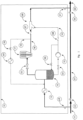
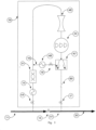
- Figure 1 shows schematically a system diagram of sub sea compressor system 10 according to a prior art solution.
- the system comprises a supply line 11 where the well flow either may flow naturally due to an excess pressure in the well through the ordinary pipe line 41, when the valves 49 and 51 are closed, while the valves 52 and 54 are open, or through the compressor system when the valves 49 and 51 are open and the valves 52 and 54 are closed.
- the well flow is fed into the compressor system 10, the well flow is fed to a liquid scrubber or separator 12, where gas and liquid/particles are separated.
- a cooler 13 Up front of the inlet to the liquid separator 12, a cooler 13 is arranged, cooling the well flow down from typically 70 °C to typically 20 "C before the well flow enters the liquid separator 12.
- the cooler 13 reduces the temperature of the well flow so that liquid is separated out and the portion of liquid is increased. This reduction of mass flow of gas which is fed into the compressor 17 reduces the power requirement in the compressor 17.
- the cooler 13 may in principle be placed upstream of the compressor 17, as shown in Figure 1 .
- a corresponding cooler may possibly also in principle be placed downstream of the compressor 17, thereby securing a temperature lower than the limiting temperature in the pipe line.
- the liquid separated out in the separator 12 is then fed through a liquid volume metering device 54 and into the pump 15.
- the metering device 54 may alternatively be arranged upstream of the pump 15. Further, the liquid from the pump 15 is returned back to the separator 12 in desired volume by regulating a valve 50. Said circulation of liquid secures a larger operational range (larger liquid volumes) through the pump 15.
- the gas separated out in the separator 12 is fed into a volume metering device 53 and then into the compressor 17.
- the compressor 17 increases the pressure in the gas from typically 40 bar to typically 120 bar. Downstream of the outlet from the compressor 17 a recirculation loop is arranged, feeding the gas through a cooler 55 and back to upstream of the separator 12 when the valve (anti-surge valve 19) is opened.
- the cooler 55 may optionally be integrated in the inlet cooler 13 by feeding re-circulated gas back upstream of the inlet cooler 13. Said recirculation of gas increases the operational range of the compressor 17, and ensure that the volume of gas through the compressor 17 is sufficient during trip and subsequent closing of the machine.
- the pressure increase in the liquid by means of the pump 15 corresponds to the pressure increase in the gas through the compressor 17.
- the gas coming from the compressor 17 is then fed through a reflux valve 57, while the liquid coming from the pump 15 goes through a non-return valve 58. Gas from the compressor 17 and liquid from the pump 15 are mixed in a Y-joint 59.
- the well flow goes further in the pipeline 20, bringing the well flow to a multiphase receiving plant (not shown).
- a post-cooler (not shown) may be incorporated.
- FIG. 2 shows a system, which does not form part of the invention.
- a multiphase flow from a well (not shown), including possible sand, is flowing through a supply line 11 into a flow conditioner 21 where the fluid flow from the well is stabilized by separating the liquid and the gas in said flow conditioner 21.
- the liquid is taken from the bottom of the flow conditioner 21 through an outlet pipe 24, while the gas is taken out at the top of the flow conditioner through an outlet pipe 23.
- an outlet pipe 16 with two separate pipes 23,24 formed as an integral gas/liquid pipe 16 in the form of separate pipes for gas and liquid is connected to a combined pump and compressor 22.
- the purpose of the combined pump and compressor unit 22 is to increase the pressure both in the gas and the liquid for further transport to a multiphase plant (not shown). This may be done, as indicated in Figure 3 , where gas and liquid are intended to be uniformly distributed and fed to a wet gas compressor 22 producing pressure increases in the gas and the liquid through same flow duct/impeller. Alternatively, this may be obtained as indicated in Figure 4 , where gas and liquid are separated at the inlet to the machine and where the gas fraction is fed to a standard gas compressor, while the separated liquid is given sufficient rotational energy so that the liquid may be transported out of the liquid chamber 44 with sufficient pressure to meet the pressure in the gas fraction at the' exit from the compressor unit.
- the outlet pipe 16 is in the form of a gas pipe 23 communicating with the upper, gas filled part of the flow conditioner 21, while an inner liquid pipe 24, having smaller diameter than the outlet pipe 16b, communicates with the lower, liquid filled part of the flow conditioner 21.
- the gas pipe 23 ends as shown in Figure 3 in the inlet pipe of the compressor 22.
- the inner liquid pipe 24 exits in a spray nozzle 23', designed to distribute the liquid evenly into the gas.
- the gas pipe 23 is connected to the inlet flange on the compressor 22.
- the liquid spray nozzle 23 is arranged at the inlet flange, close to the impeller 35 of the compressor. From the combined pump/compressor 22 the multiphase flow is exported through a pipe 20 to a multiphase receiving unit (not shown).
- the outlet pipe from the combined pump and compressor unit 22 is shown in Figures 2 and Figure 4 .
- a second outlet pipe 25 for removal of sand is arranged, if required.
- the combined compressor/pump unit 22 is preferably shut down.
- the pipe may for this purpose be equipped with a suitable valve 26. The pipe is connected in such way that if it is required to empty sand from the flow conditioner 21, the compressor is stopped, the valve (not shown) in the line 20 is closed and the valve 26 is opened while the pressure in the receiving plant is reduced.
- a cooler 13 is incorporated upstream of the flow conditioner 21.
- the purpose and temperatures are in essence corresponding to the purpose and temperatures for the prior art solution according to Figure 1 .
- an anti-surge valve may now be superfluous.
- a possible elimination of the anti-surge valve depends on the flow resistance characteristics of the pipeline and the characteristics of the compressor, and must be suitably adapted in each single case.
- the compressor characteristics have from recently performed analyses and tests shown to change for compressors which operate with two phases and because of internal recirculation for motor cooling gas, so that the need for anti-surge flow rate is reduced.
- the flow conditioner 21 may preferably be oblong in the direction of flow with a cross sectional area larger than that of the supply pipe 11, thus also contributing to enhanced separation of gas G and liquid L, and enhanced separation of possible sand in the flow.
- the lowest point in the compressor may preferably be the compressor outlet and/or inlet. This secures simple draining of the compressor 22.
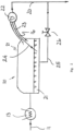
- FIG 3a shows schematically details of the flow conditioner 21, where gas G and liquid L firstly are separated in the separator 21 upstream of the impeller 35 of the unit.
- the liquid L is sucked up and delivered through the inlet pipe 24, which at its one end is provided with a constriction or a spray nozzle 23.
- the liquid L is distributed as evenly as possible in the gas flow G by means of the venturi principle, caused by the constriction in the supply line 36 of the gas pipe.
- the flow conditioner 21 may be oblong.
- an inlet pipe 27 is arranged, connected to the supply line 11.
- a lead plate 28 is arranged in order to direct the fluid flow entering the flow conditioner 21 towards its bottom area.
- Suitable, robust, insides 29 may be installed internally in the flow conditioner 21. This is an arrangement which increases the separation efficiency and evens out the liquid/gas flow.
- said insides 29 preferably also may comprise a cooler, allowing omission of a cooler placed outside the flow conditioner 21, upstream of said flow conditioner 21.
- Gas G is fed from the flow conditioner 21 to the combined pump and compressor unit 22 through an outlet pipe 23, while the liquid L is sucked up through a pipe 24.
- the gas G and the liquid L is simultaneously presses /pumped further to a multiphase receiving plant (not shown).
- the robust insides internally in the flow conditioner 21 may be in the form of a unit which optimizing slug levelling and forms basis for effective separation of liquid L and gas G, so the that liquid L and sand in a proper manner may be directed towards the bottom of the pipe.
- Collected sand may periodically be removed from the flow conditioner 21 by means of an output pipe 25 and suitable valve 26.
- the compressor 22 may be installed at a distance from the well(s), forming sufficient surface area of the inlet pipe to achieve the necessary cooling of the fluid in the pipe by means of the surrounding sea water. This depends on a possible need for protection layer on the pipe and pipe dimension (need for trenching).
- compressors may be arranged in parallel or in series. If they are arranged in series, it may be possible to construct both compressors 22 so that the system characteristic always will be to the right of the surge line. Both compressors may still be a backup for each other. The need of the function of the anti-surge valve 19 will then diminish completely or partly. If it should be necessary to consider removing the need of an anti-surge valve 19, this will mean that a start up of the compressor may be done subsequent to more or less pressure equalizing of the pipe line.
- Surge detection i.e. the lower limit for the stable flow rate of the compressor, is implemented so that by detection of too low flow rate, the compressor is closed down in order to avoid damage from mechanical vibrations. In order to protect the compressor during suddenly, unintentional down closing, necessary protective valve securing quick pressure equalizing between the inlet and outlet of the compressors may be considered.
- the liquid L and particles may be transported out by means of the compressor 22 and a constriction 36 in the inlet pipe to the compressor 22 is arranged, so that liquid L is sucked up and evenly distributed to the compressor inlet.
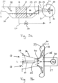
- FIG 3b shows in an enlarged scale the outlet end of the flow conditioner 21, marked A in Figure 3a .
- the gas G is fed from the conditioner 21 into a funnel shaped constriction 36 which leads to one or more impellers 35 which is brought to rotate by means of a motor 30. Due to the funnel shaped constriction 36 and the shape of the opening in the impeller 35, and also due to the rotation of the impeller 35, the liquid is in addition sucked up through the supply pipe 24 and exit through the liquid spray nozzle 23, formed of a constriction at the end of the supply pipe 24.
- the mixture of liquid L and gas G is radially fed out through the diffuser 38 and out into an annulus 39 surrounding the impeller.
- the multiphase flow is forced out at a very high pressure through a pipeline (not shown) to a multiphase receiving station (not shown).
- a seal 40 is arranged preventing unintended leakage of gas/liquid.
- Mechanical means such as bearings for the impeller 35, suspension means of the supply pipe 24 etc. are not shown.
- the motor 30 and the compressor 22 may preferably be directly connected to each other and mounted in a common pressure vessel 37, avoiding rotating seals towards the environment.
- the motor 30 may be powered by electricity, hydraulics or the like.
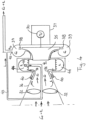
- Figure 4 shows an example where the liquid L is fed to a 0'th step comprising a spinning element 32, hurling the liquid L out towards the periphery of the constricted pipe 36 and further to a rotating chamber 44.
- a spinning element 32 Upstream of the rotating chamber 44 spinning elements 32 may be arranged, said spinning element either may be in the form of a stationary or rotating separator.
- the separating spinning element 32 separates the liquid L and the gas G, the gas G being brought to move ahead to the impeller 35 and the annulus 39 via a diffuser 38, while the liquid L is brought to flow through the inlet 34 to the rotating chamber 44.
- the inlet to the rotating chamber 44 may be provided both with internally arranged mean 32 for separation of the liquid phase with particles from the gas phase, and an annulus shaped supply duct 34 for transport of liquid in to the rotating chamber 44.
- the liquid L in the rotating chamber 44 is pressed out of the rotating chamber 44 through the opening 45 in the combined outlet pipe/pitot tube 43.
- the opening 45 is placed in such way that the opening is arranged in the section of the rotating chamber 44 being filled with liquid L.
- the exit pipe 43 for the liquid from the rotating chamber 44 is in fluid communication with the outlet 42 from the annulus 39 of the compressor. The purpose is to separate liquid L from the gas G just in front of the gas impeller 35 and to make the liquid rotate, i.e.
- the annulus 29 is also provided with a diffuser 38, arranged downstream of the exit from the impeller 35.
- the rotating liquid chamber 44 will be self-regulating in that when liquid is increasingly filled into the liquid chamber 44, the pressure at the liquid collection point will increase, thus forcing the liquid towards the compressor outlet. In such manner an increase in the liquid volume will also increase the pump capacity, so that the liquid level in the flow conditioner 21 is kept within acceptable limits.
- the rotating chamber 44 rotates together with the impeller 35.
- FIG. 5 shows a corresponding sub sea system 10 according to the invention.
- a well flow consisting of gas, liquid and particles arrives through the pipe line 11, of which a natural flow from the well is secured when the valve 13 is open and the valve 49 and 51 are closed.
- Production from the well may be increased by letting the flow from well flow in the sub sea system 10 by opening the valve 49 and the valve 51, while the valve 13 is closed.
- a cooler 13 Upstream of the inlet to the flow conditioner 21 a cooler 13 is arranged, cooling the well flow down from typically 70 °C to typically 40 °C. The cooler 13 reduces the temperature in the well flow so that liquid is separated out and the liquid portion is increased.
- a multi-phase flow meter 46 is located between the wet gas compressor 22 and flow conditioner 21.
- the multiphase flow meter 46 measures the volume of gas and liquid flowing into the wet gas compressor 22. At substantial liquid rates or pulsating supply of fluid, this may be detected by the multiphase flow meter 46, so that the regulating valve 19, (the anti-surge valve) opens, securing increased volume of gas and a stable flow regime inside the machine.
- a gas output unit 47 downstream of the compressor secures that a very small volume of liquid circulates back to the wet gas compressor 22 through the recirculation loop 18.
- a cooler 48 may be included in the recirculation loop 18, so that it may be possible to operate the wet gas compressor, while the valves 49 and 51 are closed, i.e. no supply of well flow to the sub sea system 10. It will also be possible to eliminate the cooler 48 by placing the recirculation loop 18 upstream of the cooler 13.
- the wet gas compressor 22 functions as a combined pump and compressor so that the sub sea system 10 shown in Figure 5 is simplified compared to the conventional system described in Figure 1 .
- the wet gas compressor 22 shown in Figure 5 comprises one or more impellers based on the centrifugal principle, set to rotate by an integrated powering unit, such as for example a turbine or an electromotor.
- the presence of liquid through the wet gas compressor 22 may change the operation window (surge line) of the wet gas compressor 22 and it will be important to continuously monitor possible low vibration frequencies, less than the running frequency of wet gas compressor shaft, by applying a Fast Fourier Transform analysis of the vibration signal from the rotor, which also may be measured by means of an accelerometer on the exterior of the machine housing.
- the sub- synchronous level of vibration (frequency of vibration lower than the frequency of rotation) may be used to open the control valve 19 in order to secure increased flow of gas at the inlet of the wet gas compressor 22.
- liquid at the inlet of the wet gas compressor 22 will increase the pressure ratio across the machine as a consequence of increased bulk density of the fluid. Erosion from particles is reduced since the liquid wets the rotating surfaces and prevents direct impact between the particles and the impeller. Still further, the liquid will distribute evenly in radial direction through an impeller based on the centrifugal principle, while the liquid at the same time is transferred into small droplets which easily may be transported by the gas flow. Such small droplets will at the same time secure a large interface area (surface area of contact) between the gas and the liquid so that the gas effectively may be cooled by the liquid during compression through the wet gas compressor 22.
- Such cooling of the gas during compression will reduce the power requirements while the outlet temperature from the wet gas compressor 22 at the same time will be lower than for a conventional compressor.
- a formation of a surface layer in the compressor 17 will normally be experienced in a conventional compressor system shown in Figure 1 , caused by small volumes of liquid arriving with gas containing particles which adheres to the inner surfaces of the compressor 17 when the liquid is evaporated as a consequence of increased temperature across the compressor 17.
- the volume of liquid will be significant and normally being in the range of 1-5 volume percentage at the inlet. This will secure that liquid is present across the entire machine, thus eliminating formation of a surface layer.
- a reflux valve 60 is placed downstream of the wet gas compressor 22, preventing backflow of gas and liquid into the wet gas compressor 22.
- the pressurized well flow is then directed back to the pipe line 20 through the opened valve 51 for further transport to a suitable receiving plant (not shown).
- Figure 6 shows a sub sea plant 10 according to the present invention, based on the main components shown in Figure 5 , but shown in further detail.
- a well flow comprising gas, liquid and particles is directed into the sub sea plant 10 through the pipeline 11 and the main valve 49, and then flowing through the pipe 61 which may be horizontal, but preferably slightly inclined so that a flow back towards the main line 11 is catered for during standstill.
- a vertical pipe 62 extends from the top of the horizontal pipe 61 and goes to a constriction 63 which preferably may be represented by an orifice plate or a valve.
- a minor part of the gas at the top of the horizontal pipe 61 will flow into the vertical pipe 62, while the major part of well flow will continue to the flow conditioner 21 due to less flow resistance, and then to be mixed with the gas coming from the vertical pipe 62 downstream of the flow conditioner 21.
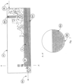
- the flow conditioner 21 in Figure 6 is disclosed in more detail in Figure 7 .
- the pipe 61 leads to the flow conditioner 21, which preferably is in the form of a cylindrical, elongated tank.
- the velocity of the gas is substantially reduced due to the increased area of flow together with use of a wall 64, securing that liquid and particles are allowed to settle in the tank 21.
- the bottom 65 of the flow conditioner 21 may be inclined downwards towards the outlet pipe 66 in order to secure that particles are not accumulated inside the tank 21, alternatively the entire flow conditioner 21 may be inclined correspondingly with respect to a horizontal plane, thus meeting said function of the bottom 65.
- Liquid and particles separated out in the tank 21 will meet a perforated wall 67 shown in more detail in the section A- A' in Figure 7 , provided with a large number of small holes 69 through which the liquid will flow and then subsequently re-mix with the gas upstream of the outlet pipe 66.
- an opening 68 as shown in Figure 7 is arranged, intended to secure that sand and other particles do not separate out and accumulate or build-up in the tank 21, but is forced out together with the liquid through the outlet pipe 66.
- the function of the flow conditioner 21 is secured in that a quick change in liquid volume at the inlet pipe 61 in Figure 6 will be smoothened out due to a change in liquid level inside the tank 21. As the level increases inside the flow conditioner 21 the liquid will flow through more and more holes 69 in the perforated wall 67, thereby increasing the supply of liquid to the outlet pipe 66.
- a wet gas compressor 22 in Figure 6 (horizontal in the Figure, but may have any orientation) which comprises one or more impeller based on the centrifugal principle, driven by an electromotor forming part of the wet gas compressor 22, receives the well flow from a vertical pipe 70 from its bottom side. The pressure increases then in the well flow through the wet gas compressor 22 and is then fed into a vertical pipe 71 arranged towards the bottom side of the wet gas compressor 22.
- a vertical inlet pipe 70 The purpose of a vertical inlet pipe 70 is to secure good drainage of liquid from the wet gas compressor 22 during a stop, and correspondingly from the multi-phase flow meter 46 and the flow conditioner 21 with associated pipe system through the orifice plate 63 and down into the pipe 61, ending into the main pipe 11.
- the liquid may also be drained out from the exit side of the wet gas compressor 22 during stop so that liquid from the outlet pipe 71, the cooler 13, gas exit unit 47, reflux valve 60, and valve 51 with associated pipes is flowing in a natural manner back to the main pipe 20.
- the gas exit unit 47 secures that very small volumes of liquid are re-circulated back upstream of the multi-phase flow meter 46.
- Such re-circulation loop 18 is normally used for increasing the volume of gas flow through the wet gas compressor 22 during stop or start of the wet gas compressor 22, but also in situations where the multi-phase flow meter 46 detects unusually high level of liquid or possibly an unstable pulsating liquid rate.
- the regulating valve 19 will also open if the appearing vibration frequencies are lower than the running frequency of the wet gas compressor shaft, which could indicate that re-circulation of gas occurs in one or more of the stationeries or rotating parts inside the wet gas compressor 22.
- process gas is used for cooling the electromotor and the bearings and is supplied from the wet gas compressor 22 in order to secure an over-pressure in these parts compared to the pressure at the inlet of the wet gas compressor 22.
- Such cooling gas extracted from the wet gas compressor 22 may contain liquids and particles since the wet gas compressor 22 is boosting an unprocessed well stream mixture. Such particles being magnetic may deposit and accumulate inside the electromotor and in and on the bearings. It is therefore proposed to use an arrangement where permanent magnetic elements are incorporated into the pipe wall or by incorporating a separate chamber in order to collect such magnetic particles prior to feeding the process gas into the area of the electromotor and the bearings. In this manner deposits of magnetic particles in the electromotor or the bearings used in the wet gas compressor 22 are avoided.
- the hot gas which has been used to cool the electromotor may be fed from the electromotor in a pipe 72 through a reflux valve 73 and into the pipe downstream of the regulating valve 19 (the anti-surge valve) in order to secure that formation of hydrates or ice are avoided during normal operation when the regulation valve is closed.
- the hot gas may be fed in to a heating jacket surrounding the regulation valve 15 in order to heat up the entire valve 15, if necessary, prior to feeding the hot gas in downstream of the regulation valve 15.
- the pressurized well flow will thus be sent from the sub sea plant 10 via the main pipe line 20 to a suitable receiving plant (not shown).
Landscapes
- Engineering & Computer Science (AREA)
- Mechanical Engineering (AREA)
- General Engineering & Computer Science (AREA)
- Mining & Mineral Resources (AREA)
- Geology (AREA)
- Life Sciences & Earth Sciences (AREA)
- Physics & Mathematics (AREA)
- Fluid Mechanics (AREA)
- General Life Sciences & Earth Sciences (AREA)
- Geochemistry & Mineralogy (AREA)
- Environmental & Geological Engineering (AREA)
- Thermal Sciences (AREA)
- Structures Of Non-Positive Displacement Pumps (AREA)
Applications Claiming Priority (2)
| Application Number | Priority Date | Filing Date | Title |
|---|---|---|---|
| NO20081911A NO328277B1 (no) | 2008-04-21 | 2008-04-21 | Gasskompresjonssystem |
| PCT/NO2009/000126 WO2009131462A2 (en) | 2008-04-21 | 2009-04-02 | Gas compression system |
Publications (2)
| Publication Number | Publication Date |
|---|---|
| EP2288786A2 EP2288786A2 (en) | 2011-03-02 |
| EP2288786B1 true EP2288786B1 (en) | 2023-08-02 |
Family
ID=40786775
Family Applications (1)
| Application Number | Title | Priority Date | Filing Date |
|---|---|---|---|
| EP09734652.2A Active EP2288786B1 (en) | 2008-04-21 | 2009-04-02 | Gas compression system |
Country Status (10)
| Country | Link |
|---|---|
| US (3) | US9032987B2 (da) |
| EP (1) | EP2288786B1 (da) |
| AU (1) | AU2009238753B2 (da) |
| BR (1) | BRPI0911223B1 (da) |
| CA (1) | CA2720678C (da) |
| DK (1) | DK178564B1 (da) |
| EA (1) | EA024584B1 (da) |
| MX (1) | MX2010011362A (da) |
| NO (1) | NO328277B1 (da) |
| WO (1) | WO2009131462A2 (da) |
Families Citing this family (41)
| Publication number | Priority date | Publication date | Assignee | Title |
|---|---|---|---|---|
| NO328277B1 (no) * | 2008-04-21 | 2010-01-18 | Statoil Asa | Gasskompresjonssystem |
| BRPI0923021B1 (pt) | 2008-12-17 | 2019-06-04 | Fluor Technologies Corporation | Método de controlar fluxo de fluído de um conduto de produção de petróleo/gás e árvore de produção de petróleo/gás. |
| NO331264B1 (no) * | 2009-12-29 | 2011-11-14 | Aker Subsea As | System og fremgangsmåte for styring av en undersjøisk plassert kompressor, samt anvendelse av en optisk sensor dertil |
| US8580002B2 (en) | 2010-07-09 | 2013-11-12 | Dresser-Rand Company | Multistage separation system |
| NO333438B1 (no) * | 2010-07-14 | 2013-06-03 | Statoil Asa | Fremgangsmate og apparat for sammensetningsbasert kompressorkontroll og ytelsesovervaking. |
| CN101915854B (zh) * | 2010-08-06 | 2011-12-14 | 中国石油大学(北京) | 一种用于测定气井出砂临界流速的装置及方法 |
| GB2493749B (en) * | 2011-08-17 | 2016-04-13 | Statoil Petroleum As | Improvements relating to subsea compression |
| US9303658B2 (en) * | 2011-11-08 | 2016-04-05 | Dresser-Rand Company | Compact turbomachine system with improved slug flow handling |
| US9624936B2 (en) | 2012-05-16 | 2017-04-18 | Compressor Controls Corporation | Turbocompressor antisurge control by vibration monitoring |
| GB201211937D0 (en) * | 2012-07-03 | 2012-08-15 | Caltec Ltd | A system to boost the pressure of multiphase well fluids and handle slugs |
| NO337108B1 (no) * | 2012-08-14 | 2016-01-25 | Aker Subsea As | Flerfase trykkforsterkningspumpe |
| EP2938372B1 (en) | 2012-12-26 | 2019-09-04 | Becton, Dickinson and Company | Pen needle assembly |
| WO2015018945A2 (en) | 2013-08-09 | 2015-02-12 | Linde Aktiengesellschaft | Subsea well stream treatment |
| US20150362198A1 (en) * | 2014-06-15 | 2015-12-17 | Unimicron Technology Corp. | Dehumidification apparatus and dehumidification method |
| US20160003255A1 (en) * | 2014-07-03 | 2016-01-07 | General Electric Company | Fluid processing system, an energy-dissipating device, and an associated method thereof |
| US10578128B2 (en) | 2014-09-18 | 2020-03-03 | General Electric Company | Fluid processing system |
| WO2016069246A1 (en) * | 2014-10-27 | 2016-05-06 | Dresser-Rand Company | Pistonless subsea pump |
| US20160138595A1 (en) * | 2014-11-13 | 2016-05-19 | General Electric Company | Subsea fluid processing system with intermediate re-circulation |
| US10801482B2 (en) | 2014-12-08 | 2020-10-13 | Saudi Arabian Oil Company | Multiphase production boost method and system |
| EP3237936B1 (en) * | 2014-12-23 | 2021-05-26 | ENI S.p.A. | Optical fiber vibration measurement system in multiphase flows with related method to monitor multiphase flows |
| FR3033371B1 (fr) * | 2015-03-06 | 2018-09-21 | Thermodyn | Separateur liquide/gaz et groupe motocompresseur centrifuge dote d'un tel separateur |
| US11022595B2 (en) | 2015-06-26 | 2021-06-01 | Statoil Petroleum As | Determining the phase composition of a fluid flow |
| US10619462B2 (en) * | 2016-06-18 | 2020-04-14 | Encline Artificial Lift Technologies LLC | Compressor for gas lift operations, and method for injecting a compressible gas mixture |
| NO341968B1 (en) * | 2015-10-09 | 2018-03-05 | Fmc Kongsberg Subsea As | Method for controlling liquid content in gas flow to a wet gas compressor |
| US9772061B2 (en) * | 2015-10-21 | 2017-09-26 | Pal Farkas | Examination process for the in situ determination of rate of feeding an inhibitor into a gas pipeline for preventing hydrate formation |
| IT201600070842A1 (it) | 2016-07-07 | 2018-01-07 | Nuovo Pignone Tecnologie Srl | Metodo e sistema di controllo anti-pompaggio adattivo |
| GB2558662B (en) | 2017-01-17 | 2021-11-24 | Equinor Energy As | Gas compressor cleaning |
| GB2559418B (en) | 2017-02-07 | 2022-01-05 | Equinor Energy As | Method and system for CO2 enhanced oil recovery |
| US11835067B2 (en) | 2017-02-10 | 2023-12-05 | Carnot Compression Inc. | Gas compressor with reduced energy loss |
| US10359055B2 (en) | 2017-02-10 | 2019-07-23 | Carnot Compression, Llc | Energy recovery-recycling turbine integrated with a capillary tube gas compressor |
| US11725672B2 (en) | 2017-02-10 | 2023-08-15 | Carnot Compression Inc. | Gas compressor with reduced energy loss |
| US11209023B2 (en) | 2017-02-10 | 2021-12-28 | Carnot Compression Inc. | Gas compressor with reduced energy loss |
| GB201705517D0 (en) * | 2017-04-05 | 2017-05-17 | Statoil Petroleum As | Fluid flow conditioning |
| BR102017009824B1 (pt) * | 2017-05-10 | 2023-12-19 | Fmc Technologies Do Brasil Ltda | Sistema para circulação de gás em espaços anulares de máquinas rotativas |
| NO344895B1 (en) * | 2018-05-14 | 2020-06-15 | Aker Solutions As | Subsea process system and method of operation |
| US11131173B2 (en) * | 2019-02-07 | 2021-09-28 | Siemens Energy, Inc. | Pump system for gas entrainment |
| IT201900023883A1 (it) * | 2019-12-13 | 2021-06-13 | Nuovo Pignone Tecnologie Srl | Compressore con un sistema per rimuovere liquido dal compressore |
| CN112811382B (zh) * | 2021-02-07 | 2025-04-22 | 中国海洋石油集团有限公司 | 一种原油罐车密闭卸油装置 |
| US20250034978A1 (en) * | 2021-12-02 | 2025-01-30 | Occidental Oil And Gas Corporation | System and method for separating gases from oil production streams |
| WO2025174717A1 (en) * | 2024-02-12 | 2025-08-21 | Schlumberger Technology Corporation | Autonomous multiphase boosting system |
| GB2641297A (en) * | 2024-05-24 | 2025-11-26 | Equinor Energy As | Fluid flow conditioning |
Citations (3)
| Publication number | Priority date | Publication date | Assignee | Title |
|---|---|---|---|---|
| US20030085036A1 (en) * | 2001-10-11 | 2003-05-08 | Curtis Glen A | Combination well kick off and gas lift booster unit |
| GB2436580A (en) * | 2006-03-30 | 2007-10-03 | Total Sa | Method and device for compressing a multiphase fluid. |
| WO2008004881A1 (en) * | 2006-07-07 | 2008-01-10 | Norsk Hydro Produksjon A.S. | Method of cooling a multiphase well effluent stream |
Family Cites Families (62)
| Publication number | Priority date | Publication date | Assignee | Title |
|---|---|---|---|---|
| CA971113A (en) * | 1970-06-15 | 1975-07-15 | Avco Corporation | Separation of liquid-liquid multiphase mixtures |
| US4144754A (en) * | 1977-03-18 | 1979-03-20 | Texaco Inc. | Multiphase fluid flow meter |
| GB8506628D0 (en) | 1985-03-14 | 1985-04-17 | Hayward Tyler Ltd | Gas compressing apparatus |
| NO863630L (no) | 1986-09-11 | 1988-03-14 | Hayward Tyler Ltd | Gasskomprimeringsapparat for gassoverfoeringsroerledninger. |
| DE3729486C1 (de) | 1987-09-03 | 1988-12-15 | Gutehoffnungshuette Man | Kompressoreinheit |
| DE3730671A1 (de) | 1987-09-12 | 1989-04-13 | Ksb Ag | Vorrichtung zur unterseeischen foerderung von erdoel und erdgas |
| NO162782C (no) | 1987-10-05 | 1990-02-14 | Kvaerner Subsea Contracting | Sentrifugalenhet og fremgangsmaate ved igangkjoering av en sentrifugalenhet. |
| US5660532A (en) | 1988-05-02 | 1997-08-26 | Institut Francais Du Petrole | Multiphase piston-type pumping system and applications of this system |
| CA1326476C (en) | 1988-09-30 | 1994-01-25 | Vaclav Kulle | Gas compressor having dry gas seals for balancing end thrust |
| CA1309996C (en) | 1988-12-13 | 1992-11-10 | Vaclav Kulle | Axial thrust reducing arrangement for gas compressor having an overhung impeller shaft |
| NO172555C (no) | 1989-01-06 | 1993-08-04 | Kvaerner Subsea Contracting As | Undervannsstasjon for behandling og transport av en broennstroem |
| DE3901771A1 (de) | 1989-01-21 | 1990-08-02 | Palitex Project Co Gmbh | Verfahren zum transport eines spulenpaketes aus mindestens zwei garnspulen zu einer zwirnmaschine sowie einrichtung zur durchfuehrung des verfahrens |
| US5254292A (en) * | 1989-02-02 | 1993-10-19 | Institut Francais Du Petrole | Device for regulating and reducing the fluctuations in a polyphasic flow, and its use |
| GB8921071D0 (en) | 1989-09-18 | 1989-11-01 | Framo Dev Ltd | Pump or compressor unit |
| GB8925402D0 (en) * | 1989-11-10 | 1989-12-28 | British Hydromechanics | Pumping liquid/gas mixture |
| IT1245119B (it) | 1991-01-29 | 1994-09-13 | Nuovopignone Ind Meccaniche Ef | Sistema perfezionato di recupero dell'olio di lubrificazione per i cuscini di un compressore centrifugo con tenute a labirinto |
| NO172075C (no) | 1991-02-08 | 1993-06-02 | Kvaerner Rosenberg As Kvaerner | Fremgangsmaate ved drift av et kompressoranlegg i en undervannstasjon for transport av en broennstroem og kompressoranlegg i en undervannstasjon for transport av en broennstroem |
| NO172076C (no) | 1991-02-08 | 1993-06-02 | Kvaerner Rosenberg As Kvaerner | Kompressoranlegg i en undervannstasjon for transport av en broennstroem |
| NO172556C (no) | 1991-02-08 | 1993-08-04 | Kvaerner Rosenberg As Kvaerner | Kompressoranlegg i en undervannstasjon for transport av en broennstroem |
| IT1248296B (it) | 1991-04-11 | 1995-01-05 | Nuovopignone Ind Meccaniche Ef | Perfezionamento del sistema di sbarramento per l'olio di lubrificazione dei cuscini di un compressore centrifugo con tenute a labirinti installato in ambiente confinato |
| NO173197C (no) | 1991-07-10 | 1993-11-10 | Kvaerner Rosenberg As Kvaerner | Fremgangsmaate ved drift av et kompressoranlegg og kompressoranlegg |
| FR2685738B1 (fr) * | 1991-12-27 | 1995-12-08 | Inst Francais Du Petrole | Procede et dispositif permettant d'optimiser le transfert par pompage d'effluents polyphasiques. |
| GB2264147A (en) * | 1992-02-12 | 1993-08-18 | Peco Machine Shop & Inspection | Multi-phase pumping arrangement |
| US5576495A (en) * | 1995-10-23 | 1996-11-19 | The Babcock & Wilcox Company | Two phase flow meter |
| US5795135A (en) | 1995-12-05 | 1998-08-18 | Westinghouse Electric Corp. | Sub-sea pumping system and an associated method including pressure compensating arrangement for cooling and lubricating fluid |
| US6059539A (en) | 1995-12-05 | 2000-05-09 | Westinghouse Government Services Company Llc | Sub-sea pumping system and associated method including pressure compensating arrangement for cooling and lubricating |
| FR2771024B1 (fr) * | 1997-11-19 | 1999-12-31 | Inst Francais Du Petrole | Dispositif et procede de compression diphasique d'un gaz soluble dans un solvant |
| EA002667B1 (ru) * | 1998-01-09 | 2002-08-29 | Ден Норске Статс Ольесельскап А.С. | Введение воздуха в воду |
| FR2774135B1 (fr) * | 1998-01-28 | 2000-04-07 | Inst Francais Du Petrole | Dispositif et methode de compression pour gaz humide avec evaporation du liquide |
| FR2774137B1 (fr) | 1998-01-28 | 2000-02-18 | Inst Francais Du Petrole | Dispositif de compression de gaz humide comportant un etage de compression/separation integrees |
| FR2774136B1 (fr) | 1998-01-28 | 2000-02-25 | Inst Francais Du Petrole | Dispositif de compression-pompage monoarbre associe a un separateur |
| US6164308A (en) | 1998-08-28 | 2000-12-26 | Butler; Bryan V. | System and method for handling multiphase flow |
| FR2783884B1 (fr) * | 1998-09-24 | 2000-10-27 | Inst Francais Du Petrole | Systeme de compression-pompage comportant une section de compression en fonctionnement alterne et son procede |
| US6214092B1 (en) * | 1998-11-12 | 2001-04-10 | Larry G. Odom | Fracturing material separator apparatus |
| DE19854539C1 (de) * | 1998-11-26 | 2000-04-06 | Daimler Chrysler Ag | Belüftungsvorrichtung für Fahrzeuge |
| GB9912666D0 (en) * | 1999-05-29 | 1999-07-28 | Specialised Petroleum Serv Ltd | Magnetic well cleaning apparatus |
| US6773235B2 (en) * | 1999-12-31 | 2004-08-10 | Shell Oil Company | Rotodynamic multi-phase flow booster pump |
| NL1018212C2 (nl) | 2001-06-05 | 2002-12-10 | Siemens Demag Delaval Turbomac | Compressoreenheid omvattende een centrifugaalcompressor en een elektromotor. |
| ATE343726T1 (de) | 2001-06-06 | 2006-11-15 | Howden Power As | Luftauslasseinheit für grosse gebläseanordnung |
| US6592654B2 (en) * | 2001-06-25 | 2003-07-15 | Cryogenic Group Inc. | Liquid extraction and separation method for treating fluids utilizing flow swirl |
| US6644400B2 (en) * | 2001-10-11 | 2003-11-11 | Abi Technology, Inc. | Backwash oil and gas production |
| GB0124617D0 (en) * | 2001-10-12 | 2001-12-05 | Alpha Thames Eng | Method and apparatus for collecting sand contained in production fluid and disposing of the collected sand |
| GB0124614D0 (en) * | 2001-10-12 | 2001-12-05 | Alpha Thames Ltd | Multiphase fluid conveyance system |
| DE50206223D1 (de) * | 2001-10-22 | 2006-05-18 | Sulzer Pumpen Ag | Wellenabdichtungsanordnung für eine Pumpe zur Förderung heisser Fluide |
| NO20015199L (no) | 2001-10-24 | 2003-04-25 | Kvaerner Eureka As | Fremgangsmåte ved drift av en undervannsplassert, roterende innretning og en anordning ved en slik innretning |
| GB0204139D0 (en) | 2002-02-21 | 2002-04-10 | Alpha Thames Ltd | Electric motor protection system |
| NL1021656C2 (nl) | 2002-10-15 | 2004-04-16 | Siemens Demag Delaval Turbomac | Compressoreenheid met gemeenschappelijke behuizing voor elektromotor en compressor, werkwijze voor het vervaardigen van een scheidingswand voor een compressoreenheid en gebruik van een compressoreenheid. |
| ITMI20022337A1 (it) | 2002-11-05 | 2004-05-06 | Nuovo Pignone Spa | Assieme di bilanciamento di spinta assiale per un |
| NO320427B1 (no) * | 2002-12-23 | 2005-12-05 | Norsk Hydro As | Et system og fremgangsmate for a forutsi og handtere vaeske- eller gassplugger i et rorledningssystem |
| US6907933B2 (en) * | 2003-02-13 | 2005-06-21 | Conocophillips Company | Sub-sea blow case compressor |
| HUE029908T2 (hu) | 2003-03-10 | 2017-04-28 | Thermodyn | Centrifugálkompresszor egység |
| EP1613864B1 (fr) | 2003-04-11 | 2015-10-14 | Thermodyn | Groupe moto-compresseur centrifuge |
| FR2853700B1 (fr) | 2003-04-11 | 2006-06-16 | Thermodyn | Groupe moto-compresseur centrifuge a refrigeration assistee. |
| JP4009953B2 (ja) | 2003-05-14 | 2007-11-21 | オムロン株式会社 | 物体検知センサ |
| NO323324B1 (no) | 2003-07-02 | 2007-03-19 | Kvaerner Oilfield Prod As | Fremgangsmate for regulering at trykket i en undervannskompressormodul |
| NO323240B1 (no) | 2003-07-02 | 2007-02-12 | Kvaerner Oilfield Prod As | Anordning for regulering av trykket i undervanns kompressormodul |
| NO321304B1 (no) * | 2003-09-12 | 2006-04-24 | Kvaerner Oilfield Prod As | Undervanns kompressorstasjon |
| NO20055727L (no) * | 2005-12-05 | 2007-06-06 | Norsk Hydro Produksjon As | Elektrisk undervanns kompresjonssystem |
| US7686086B2 (en) * | 2005-12-08 | 2010-03-30 | Vetco Gray Inc. | Subsea well separation and reinjection system |
| US7448447B2 (en) * | 2006-02-27 | 2008-11-11 | Schlumberger Technology Corporation | Real-time production-side monitoring and control for heat assisted fluid recovery applications |
| NO325702B1 (no) * | 2006-07-06 | 2008-07-07 | Compressed Energy Tech As | System, fartøy og fremgangsmåte for produksjon av olje og tyngre gassfraksjoner fra et reservoar under havbunnen |
| NO328277B1 (no) * | 2008-04-21 | 2010-01-18 | Statoil Asa | Gasskompresjonssystem |
-
2008
- 2008-04-21 NO NO20081911A patent/NO328277B1/no unknown
-
2009
- 2009-04-02 US US12/988,769 patent/US9032987B2/en active Active
- 2009-04-02 BR BRPI0911223-5A patent/BRPI0911223B1/pt active IP Right Grant
- 2009-04-02 MX MX2010011362A patent/MX2010011362A/es active IP Right Grant
- 2009-04-02 EA EA201071220A patent/EA024584B1/ru not_active IP Right Cessation
- 2009-04-02 AU AU2009238753A patent/AU2009238753B2/en active Active
- 2009-04-02 EP EP09734652.2A patent/EP2288786B1/en active Active
- 2009-04-02 CA CA2720678A patent/CA2720678C/en active Active
- 2009-04-02 WO PCT/NO2009/000126 patent/WO2009131462A2/en not_active Ceased
- 2009-12-21 DK DKPA200970290A patent/DK178564B1/da not_active IP Right Cessation
-
2015
- 2015-04-24 US US14/696,008 patent/US9784076B2/en active Active
- 2015-04-24 US US14/695,836 patent/US9784075B2/en active Active
Patent Citations (3)
| Publication number | Priority date | Publication date | Assignee | Title |
|---|---|---|---|---|
| US20030085036A1 (en) * | 2001-10-11 | 2003-05-08 | Curtis Glen A | Combination well kick off and gas lift booster unit |
| GB2436580A (en) * | 2006-03-30 | 2007-10-03 | Total Sa | Method and device for compressing a multiphase fluid. |
| WO2008004881A1 (en) * | 2006-07-07 | 2008-01-10 | Norsk Hydro Produksjon A.S. | Method of cooling a multiphase well effluent stream |
Also Published As
| Publication number | Publication date |
|---|---|
| BRPI0911223A2 (pt) | 2015-09-29 |
| NO20081911L (no) | 2009-04-29 |
| BRPI0911223B1 (pt) | 2019-08-06 |
| WO2009131462A3 (en) | 2010-01-07 |
| US20150322763A1 (en) | 2015-11-12 |
| US9032987B2 (en) | 2015-05-19 |
| EP2288786A2 (en) | 2011-03-02 |
| US20150322749A1 (en) | 2015-11-12 |
| AU2009238753B2 (en) | 2015-04-23 |
| DK178564B1 (da) | 2016-06-27 |
| DK200970290A (en) | 2009-12-21 |
| EA024584B1 (ru) | 2016-10-31 |
| CA2720678A1 (en) | 2009-10-29 |
| CA2720678C (en) | 2018-02-13 |
| AU2009238753A1 (en) | 2009-10-29 |
| US9784075B2 (en) | 2017-10-10 |
| WO2009131462A2 (en) | 2009-10-29 |
| US20110048546A1 (en) | 2011-03-03 |
| EA201071220A1 (ru) | 2011-10-31 |
| NO328277B1 (no) | 2010-01-18 |
| US9784076B2 (en) | 2017-10-10 |
| MX2010011362A (es) | 2010-11-09 |
Similar Documents
| Publication | Publication Date | Title |
|---|---|---|
| EP2288786B1 (en) | Gas compression system | |
| US8771394B2 (en) | Device for separating and collecting fluid in gas from a reservoir | |
| EP2029893B1 (en) | Improvements in subsea multiphase pumping systems | |
| US9566542B2 (en) | Method and a device for liquid treatment when compressing a well flow | |
| US6171074B1 (en) | Single-shaft compression-pumping device associated with a separator | |
| US7708059B2 (en) | Subsea well having a submersible pump assembly with a gas separator located at the pump discharge | |
| AU2015202860B2 (en) | Combined multi-phase pump and compressor unit and gas compression system | |
| AU2019219857B2 (en) | Multiphase pump | |
| US8585893B2 (en) | Particle collector with weight measuring | |
| CN202117650U (zh) | 油气混输液体回注系统 | |
| RU2586225C1 (ru) | Нагнетающая установка для транспортировки продукции нефтяных скважин с высоким газовым фактором и способ ее работы | |
| EP0554937A1 (en) | Liquid ring pump | |
| Bakken et al. | An Experimental Investigation on Hysteresis in a Wet Gas Compressor |
Legal Events
| Date | Code | Title | Description |
|---|---|---|---|
| PUAI | Public reference made under article 153(3) epc to a published international application that has entered the european phase |
Free format text: ORIGINAL CODE: 0009012 |
|
| 17P | Request for examination filed |
Effective date: 20101109 |
|
| AK | Designated contracting states |
Kind code of ref document: A2 Designated state(s): AT BE BG CH CY CZ DE DK EE ES FI FR GB GR HR HU IE IS IT LI LT LU LV MC MK MT NL NO PL PT RO SE SI SK TR |
|
| AX | Request for extension of the european patent |
Extension state: AL BA RS |
|
| DAX | Request for extension of the european patent (deleted) | ||
| RAP1 | Party data changed (applicant data changed or rights of an application transferred) |
Owner name: STATOIL PETROLEUM AS |
|
| 17Q | First examination report despatched |
Effective date: 20141022 |
|
| STAA | Information on the status of an ep patent application or granted ep patent |
Free format text: STATUS: EXAMINATION IS IN PROGRESS |
|
| RAP1 | Party data changed (applicant data changed or rights of an application transferred) |
Owner name: EQUINOR ENERGY AS |
|
| GRAP | Despatch of communication of intention to grant a patent |
Free format text: ORIGINAL CODE: EPIDOSNIGR1 |
|
| STAA | Information on the status of an ep patent application or granted ep patent |
Free format text: STATUS: GRANT OF PATENT IS INTENDED |
|
| INTG | Intention to grant announced |
Effective date: 20230222 |
|
| GRAS | Grant fee paid |
Free format text: ORIGINAL CODE: EPIDOSNIGR3 |
|
| GRAA | (expected) grant |
Free format text: ORIGINAL CODE: 0009210 |
|
| STAA | Information on the status of an ep patent application or granted ep patent |
Free format text: STATUS: THE PATENT HAS BEEN GRANTED |
|
| AK | Designated contracting states |
Kind code of ref document: B1 Designated state(s): AT BE BG CH CY CZ DE DK EE ES FI FR GB GR HR HU IE IS IT LI LT LU LV MC MK MT NL NO PL PT RO SE SI SK TR |
|
| REG | Reference to a national code |
Ref country code: GB Ref legal event code: FG4D |
|
| REG | Reference to a national code |
Ref country code: CH Ref legal event code: EP |
|
| REG | Reference to a national code |
Ref country code: DE Ref legal event code: R096 Ref document number: 602009064943 Country of ref document: DE |
|
| REG | Reference to a national code |
Ref country code: IE Ref legal event code: FG4D |
|
| REG | Reference to a national code |
Ref country code: LT Ref legal event code: MG9D |
|
| REG | Reference to a national code |
Ref country code: NL Ref legal event code: MP Effective date: 20230802 |
|
| REG | Reference to a national code |
Ref country code: AT Ref legal event code: MK05 Ref document number: 1594970 Country of ref document: AT Kind code of ref document: T Effective date: 20230802 |
|
| PG25 | Lapsed in a contracting state [announced via postgrant information from national office to epo] |
Ref country code: GR Free format text: LAPSE BECAUSE OF FAILURE TO SUBMIT A TRANSLATION OF THE DESCRIPTION OR TO PAY THE FEE WITHIN THE PRESCRIBED TIME-LIMIT Effective date: 20231103 |
|
| PG25 | Lapsed in a contracting state [announced via postgrant information from national office to epo] |
Ref country code: IS Free format text: LAPSE BECAUSE OF FAILURE TO SUBMIT A TRANSLATION OF THE DESCRIPTION OR TO PAY THE FEE WITHIN THE PRESCRIBED TIME-LIMIT Effective date: 20231202 |
|
| PG25 | Lapsed in a contracting state [announced via postgrant information from national office to epo] |
Ref country code: SE Free format text: LAPSE BECAUSE OF FAILURE TO SUBMIT A TRANSLATION OF THE DESCRIPTION OR TO PAY THE FEE WITHIN THE PRESCRIBED TIME-LIMIT Effective date: 20230802 Ref country code: PT Free format text: LAPSE BECAUSE OF FAILURE TO SUBMIT A TRANSLATION OF THE DESCRIPTION OR TO PAY THE FEE WITHIN THE PRESCRIBED TIME-LIMIT Effective date: 20231204 Ref country code: NO Free format text: LAPSE BECAUSE OF FAILURE TO SUBMIT A TRANSLATION OF THE DESCRIPTION OR TO PAY THE FEE WITHIN THE PRESCRIBED TIME-LIMIT Effective date: 20231102 Ref country code: NL Free format text: LAPSE BECAUSE OF FAILURE TO SUBMIT A TRANSLATION OF THE DESCRIPTION OR TO PAY THE FEE WITHIN THE PRESCRIBED TIME-LIMIT Effective date: 20230802 Ref country code: LV Free format text: LAPSE BECAUSE OF FAILURE TO SUBMIT A TRANSLATION OF THE DESCRIPTION OR TO PAY THE FEE WITHIN THE PRESCRIBED TIME-LIMIT Effective date: 20230802 Ref country code: LT Free format text: LAPSE BECAUSE OF FAILURE TO SUBMIT A TRANSLATION OF THE DESCRIPTION OR TO PAY THE FEE WITHIN THE PRESCRIBED TIME-LIMIT Effective date: 20230802 Ref country code: IS Free format text: LAPSE BECAUSE OF FAILURE TO SUBMIT A TRANSLATION OF THE DESCRIPTION OR TO PAY THE FEE WITHIN THE PRESCRIBED TIME-LIMIT Effective date: 20231202 Ref country code: HR Free format text: LAPSE BECAUSE OF FAILURE TO SUBMIT A TRANSLATION OF THE DESCRIPTION OR TO PAY THE FEE WITHIN THE PRESCRIBED TIME-LIMIT Effective date: 20230802 Ref country code: GR Free format text: LAPSE BECAUSE OF FAILURE TO SUBMIT A TRANSLATION OF THE DESCRIPTION OR TO PAY THE FEE WITHIN THE PRESCRIBED TIME-LIMIT Effective date: 20231103 Ref country code: FI Free format text: LAPSE BECAUSE OF FAILURE TO SUBMIT A TRANSLATION OF THE DESCRIPTION OR TO PAY THE FEE WITHIN THE PRESCRIBED TIME-LIMIT Effective date: 20230802 Ref country code: AT Free format text: LAPSE BECAUSE OF FAILURE TO SUBMIT A TRANSLATION OF THE DESCRIPTION OR TO PAY THE FEE WITHIN THE PRESCRIBED TIME-LIMIT Effective date: 20230802 |
|
| PG25 | Lapsed in a contracting state [announced via postgrant information from national office to epo] |
Ref country code: PL Free format text: LAPSE BECAUSE OF FAILURE TO SUBMIT A TRANSLATION OF THE DESCRIPTION OR TO PAY THE FEE WITHIN THE PRESCRIBED TIME-LIMIT Effective date: 20230802 |
|
| PG25 | Lapsed in a contracting state [announced via postgrant information from national office to epo] |
Ref country code: ES Free format text: LAPSE BECAUSE OF FAILURE TO SUBMIT A TRANSLATION OF THE DESCRIPTION OR TO PAY THE FEE WITHIN THE PRESCRIBED TIME-LIMIT Effective date: 20230802 |
|
| PG25 | Lapsed in a contracting state [announced via postgrant information from national office to epo] |
Ref country code: RO Free format text: LAPSE BECAUSE OF FAILURE TO SUBMIT A TRANSLATION OF THE DESCRIPTION OR TO PAY THE FEE WITHIN THE PRESCRIBED TIME-LIMIT Effective date: 20230802 Ref country code: ES Free format text: LAPSE BECAUSE OF FAILURE TO SUBMIT A TRANSLATION OF THE DESCRIPTION OR TO PAY THE FEE WITHIN THE PRESCRIBED TIME-LIMIT Effective date: 20230802 Ref country code: EE Free format text: LAPSE BECAUSE OF FAILURE TO SUBMIT A TRANSLATION OF THE DESCRIPTION OR TO PAY THE FEE WITHIN THE PRESCRIBED TIME-LIMIT Effective date: 20230802 Ref country code: DK Free format text: LAPSE BECAUSE OF FAILURE TO SUBMIT A TRANSLATION OF THE DESCRIPTION OR TO PAY THE FEE WITHIN THE PRESCRIBED TIME-LIMIT Effective date: 20230802 Ref country code: CZ Free format text: LAPSE BECAUSE OF FAILURE TO SUBMIT A TRANSLATION OF THE DESCRIPTION OR TO PAY THE FEE WITHIN THE PRESCRIBED TIME-LIMIT Effective date: 20230802 Ref country code: SK Free format text: LAPSE BECAUSE OF FAILURE TO SUBMIT A TRANSLATION OF THE DESCRIPTION OR TO PAY THE FEE WITHIN THE PRESCRIBED TIME-LIMIT Effective date: 20230802 |
|
| REG | Reference to a national code |
Ref country code: DE Ref legal event code: R097 Ref document number: 602009064943 Country of ref document: DE |
|
| PG25 | Lapsed in a contracting state [announced via postgrant information from national office to epo] |
Ref country code: IT Free format text: LAPSE BECAUSE OF FAILURE TO SUBMIT A TRANSLATION OF THE DESCRIPTION OR TO PAY THE FEE WITHIN THE PRESCRIBED TIME-LIMIT Effective date: 20230802 |
|
| PLBE | No opposition filed within time limit |
Free format text: ORIGINAL CODE: 0009261 |
|
| STAA | Information on the status of an ep patent application or granted ep patent |
Free format text: STATUS: NO OPPOSITION FILED WITHIN TIME LIMIT |
|
| 26N | No opposition filed |
Effective date: 20240503 |
|
| PG25 | Lapsed in a contracting state [announced via postgrant information from national office to epo] |
Ref country code: SI Free format text: LAPSE BECAUSE OF FAILURE TO SUBMIT A TRANSLATION OF THE DESCRIPTION OR TO PAY THE FEE WITHIN THE PRESCRIBED TIME-LIMIT Effective date: 20230802 |
|
| REG | Reference to a national code |
Ref country code: DE Ref legal event code: R119 Ref document number: 602009064943 Country of ref document: DE |
|
| PG25 | Lapsed in a contracting state [announced via postgrant information from national office to epo] |
Ref country code: BG Free format text: LAPSE BECAUSE OF FAILURE TO SUBMIT A TRANSLATION OF THE DESCRIPTION OR TO PAY THE FEE WITHIN THE PRESCRIBED TIME-LIMIT Effective date: 20230802 |
|
| PG25 | Lapsed in a contracting state [announced via postgrant information from national office to epo] |
Ref country code: MC Free format text: LAPSE BECAUSE OF FAILURE TO SUBMIT A TRANSLATION OF THE DESCRIPTION OR TO PAY THE FEE WITHIN THE PRESCRIBED TIME-LIMIT Effective date: 20230802 |
|
| PG25 | Lapsed in a contracting state [announced via postgrant information from national office to epo] |
Ref country code: MC Free format text: LAPSE BECAUSE OF FAILURE TO SUBMIT A TRANSLATION OF THE DESCRIPTION OR TO PAY THE FEE WITHIN THE PRESCRIBED TIME-LIMIT Effective date: 20230802 Ref country code: BG Free format text: LAPSE BECAUSE OF FAILURE TO SUBMIT A TRANSLATION OF THE DESCRIPTION OR TO PAY THE FEE WITHIN THE PRESCRIBED TIME-LIMIT Effective date: 20230802 |
|
| REG | Reference to a national code |
Ref country code: CH Ref legal event code: PL |
|
| PG25 | Lapsed in a contracting state [announced via postgrant information from national office to epo] |
Ref country code: LU Free format text: LAPSE BECAUSE OF NON-PAYMENT OF DUE FEES Effective date: 20240402 |
|
| GBPC | Gb: european patent ceased through non-payment of renewal fee |
Effective date: 20240402 |
|
| REG | Reference to a national code |
Ref country code: BE Ref legal event code: MM Effective date: 20240430 |
|
| PG25 | Lapsed in a contracting state [announced via postgrant information from national office to epo] |
Ref country code: LU Free format text: LAPSE BECAUSE OF NON-PAYMENT OF DUE FEES Effective date: 20240402 |
|
| PG25 | Lapsed in a contracting state [announced via postgrant information from national office to epo] |
Ref country code: DE Free format text: LAPSE BECAUSE OF NON-PAYMENT OF DUE FEES Effective date: 20241105 |
|
| PG25 | Lapsed in a contracting state [announced via postgrant information from national office to epo] |
Ref country code: BE Free format text: LAPSE BECAUSE OF NON-PAYMENT OF DUE FEES Effective date: 20240430 |
|
| PG25 | Lapsed in a contracting state [announced via postgrant information from national office to epo] |
Ref country code: GB Free format text: LAPSE BECAUSE OF NON-PAYMENT OF DUE FEES Effective date: 20240402 |
|
| PG25 | Lapsed in a contracting state [announced via postgrant information from national office to epo] |
Ref country code: FR Free format text: LAPSE BECAUSE OF NON-PAYMENT OF DUE FEES Effective date: 20240430 |
|
| PG25 | Lapsed in a contracting state [announced via postgrant information from national office to epo] |
Ref country code: GB Free format text: LAPSE BECAUSE OF NON-PAYMENT OF DUE FEES Effective date: 20240402 Ref country code: FR Free format text: LAPSE BECAUSE OF NON-PAYMENT OF DUE FEES Effective date: 20240430 Ref country code: DE Free format text: LAPSE BECAUSE OF NON-PAYMENT OF DUE FEES Effective date: 20241105 Ref country code: BE Free format text: LAPSE BECAUSE OF NON-PAYMENT OF DUE FEES Effective date: 20240430 Ref country code: CH Free format text: LAPSE BECAUSE OF NON-PAYMENT OF DUE FEES Effective date: 20240430 |
|
| PG25 | Lapsed in a contracting state [announced via postgrant information from national office to epo] |
Ref country code: IE Free format text: LAPSE BECAUSE OF NON-PAYMENT OF DUE FEES Effective date: 20240402 |
|
| PG25 | Lapsed in a contracting state [announced via postgrant information from national office to epo] |
Ref country code: CY Free format text: LAPSE BECAUSE OF FAILURE TO SUBMIT A TRANSLATION OF THE DESCRIPTION OR TO PAY THE FEE WITHIN THE PRESCRIBED TIME-LIMIT; INVALID AB INITIO Effective date: 20090402 |
|
| PG25 | Lapsed in a contracting state [announced via postgrant information from national office to epo] |
Ref country code: HU Free format text: LAPSE BECAUSE OF FAILURE TO SUBMIT A TRANSLATION OF THE DESCRIPTION OR TO PAY THE FEE WITHIN THE PRESCRIBED TIME-LIMIT; INVALID AB INITIO Effective date: 20090402 |
|
| PG25 | Lapsed in a contracting state [announced via postgrant information from national office to epo] |
Ref country code: TR Free format text: LAPSE BECAUSE OF FAILURE TO SUBMIT A TRANSLATION OF THE DESCRIPTION OR TO PAY THE FEE WITHIN THE PRESCRIBED TIME-LIMIT Effective date: 20230802 |