EP2288523B1 - Monitoring device for monitoring vehicle systems - Google Patents
Monitoring device for monitoring vehicle systems Download PDFInfo
- Publication number
- EP2288523B1 EP2288523B1 EP09765562A EP09765562A EP2288523B1 EP 2288523 B1 EP2288523 B1 EP 2288523B1 EP 09765562 A EP09765562 A EP 09765562A EP 09765562 A EP09765562 A EP 09765562A EP 2288523 B1 EP2288523 B1 EP 2288523B1
- Authority
- EP
- European Patent Office
- Prior art keywords
- monitoring
- ecpb
- ebs
- ecu
- pressure
- Prior art date
- Legal status (The legal status is an assumption and is not a legal conclusion. Google has not performed a legal analysis and makes no representation as to the accuracy of the status listed.)
- Active
Links
Images


Classifications
-
- B—PERFORMING OPERATIONS; TRANSPORTING
- B60—VEHICLES IN GENERAL
- B60T—VEHICLE BRAKE CONTROL SYSTEMS OR PARTS THEREOF; BRAKE CONTROL SYSTEMS OR PARTS THEREOF, IN GENERAL; ARRANGEMENT OF BRAKING ELEMENTS ON VEHICLES IN GENERAL; PORTABLE DEVICES FOR PREVENTING UNWANTED MOVEMENT OF VEHICLES; VEHICLE MODIFICATIONS TO FACILITATE COOLING OF BRAKES
- B60T8/00—Arrangements for adjusting wheel-braking force to meet varying vehicular or ground-surface conditions, e.g. limiting or varying distribution of braking force
- B60T8/32—Arrangements for adjusting wheel-braking force to meet varying vehicular or ground-surface conditions, e.g. limiting or varying distribution of braking force responsive to a speed condition, e.g. acceleration or deceleration
- B60T8/88—Arrangements for adjusting wheel-braking force to meet varying vehicular or ground-surface conditions, e.g. limiting or varying distribution of braking force responsive to a speed condition, e.g. acceleration or deceleration with failure responsive means, i.e. means for detecting and indicating faulty operation of the speed responsive control means
- B60T8/90—Arrangements for adjusting wheel-braking force to meet varying vehicular or ground-surface conditions, e.g. limiting or varying distribution of braking force responsive to a speed condition, e.g. acceleration or deceleration with failure responsive means, i.e. means for detecting and indicating faulty operation of the speed responsive control means using a simulated speed signal to test speed responsive control means
-
- B—PERFORMING OPERATIONS; TRANSPORTING
- B60—VEHICLES IN GENERAL
- B60T—VEHICLE BRAKE CONTROL SYSTEMS OR PARTS THEREOF; BRAKE CONTROL SYSTEMS OR PARTS THEREOF, IN GENERAL; ARRANGEMENT OF BRAKING ELEMENTS ON VEHICLES IN GENERAL; PORTABLE DEVICES FOR PREVENTING UNWANTED MOVEMENT OF VEHICLES; VEHICLE MODIFICATIONS TO FACILITATE COOLING OF BRAKES
- B60T13/00—Transmitting braking action from initiating means to ultimate brake actuator with power assistance or drive; Brake systems incorporating such transmitting means, e.g. air-pressure brake systems
- B60T13/10—Transmitting braking action from initiating means to ultimate brake actuator with power assistance or drive; Brake systems incorporating such transmitting means, e.g. air-pressure brake systems with fluid assistance, drive, or release
- B60T13/66—Electrical control in fluid-pressure brake systems
- B60T13/662—Electrical control in fluid-pressure brake systems characterised by specified functions of the control system components
-
- B—PERFORMING OPERATIONS; TRANSPORTING
- B60—VEHICLES IN GENERAL
- B60T—VEHICLE BRAKE CONTROL SYSTEMS OR PARTS THEREOF; BRAKE CONTROL SYSTEMS OR PARTS THEREOF, IN GENERAL; ARRANGEMENT OF BRAKING ELEMENTS ON VEHICLES IN GENERAL; PORTABLE DEVICES FOR PREVENTING UNWANTED MOVEMENT OF VEHICLES; VEHICLE MODIFICATIONS TO FACILITATE COOLING OF BRAKES
- B60T13/00—Transmitting braking action from initiating means to ultimate brake actuator with power assistance or drive; Brake systems incorporating such transmitting means, e.g. air-pressure brake systems
- B60T13/10—Transmitting braking action from initiating means to ultimate brake actuator with power assistance or drive; Brake systems incorporating such transmitting means, e.g. air-pressure brake systems with fluid assistance, drive, or release
- B60T13/66—Electrical control in fluid-pressure brake systems
- B60T13/68—Electrical control in fluid-pressure brake systems by electrically-controlled valves
- B60T13/683—Electrical control in fluid-pressure brake systems by electrically-controlled valves in pneumatic systems or parts thereof
-
- B—PERFORMING OPERATIONS; TRANSPORTING
- B60—VEHICLES IN GENERAL
- B60T—VEHICLE BRAKE CONTROL SYSTEMS OR PARTS THEREOF; BRAKE CONTROL SYSTEMS OR PARTS THEREOF, IN GENERAL; ARRANGEMENT OF BRAKING ELEMENTS ON VEHICLES IN GENERAL; PORTABLE DEVICES FOR PREVENTING UNWANTED MOVEMENT OF VEHICLES; VEHICLE MODIFICATIONS TO FACILITATE COOLING OF BRAKES
- B60T17/00—Component parts, details, or accessories of power brake systems not covered by groups B60T8/00, B60T13/00 or B60T15/00, or presenting other characteristic features
- B60T17/18—Safety devices; Monitoring
- B60T17/22—Devices for monitoring or checking brake systems; Signal devices
- B60T17/221—Procedure or apparatus for checking or keeping in a correct functioning condition of brake systems
-
- B—PERFORMING OPERATIONS; TRANSPORTING
- B60—VEHICLES IN GENERAL
- B60T—VEHICLE BRAKE CONTROL SYSTEMS OR PARTS THEREOF; BRAKE CONTROL SYSTEMS OR PARTS THEREOF, IN GENERAL; ARRANGEMENT OF BRAKING ELEMENTS ON VEHICLES IN GENERAL; PORTABLE DEVICES FOR PREVENTING UNWANTED MOVEMENT OF VEHICLES; VEHICLE MODIFICATIONS TO FACILITATE COOLING OF BRAKES
- B60T8/00—Arrangements for adjusting wheel-braking force to meet varying vehicular or ground-surface conditions, e.g. limiting or varying distribution of braking force
- B60T8/17—Using electrical or electronic regulation means to control braking
- B60T8/1701—Braking or traction control means specially adapted for particular types of vehicles
- B60T8/1708—Braking or traction control means specially adapted for particular types of vehicles for lorries or tractor-trailer combinations
-
- B—PERFORMING OPERATIONS; TRANSPORTING
- B60—VEHICLES IN GENERAL
- B60T—VEHICLE BRAKE CONTROL SYSTEMS OR PARTS THEREOF; BRAKE CONTROL SYSTEMS OR PARTS THEREOF, IN GENERAL; ARRANGEMENT OF BRAKING ELEMENTS ON VEHICLES IN GENERAL; PORTABLE DEVICES FOR PREVENTING UNWANTED MOVEMENT OF VEHICLES; VEHICLE MODIFICATIONS TO FACILITATE COOLING OF BRAKES
- B60T8/00—Arrangements for adjusting wheel-braking force to meet varying vehicular or ground-surface conditions, e.g. limiting or varying distribution of braking force
- B60T8/32—Arrangements for adjusting wheel-braking force to meet varying vehicular or ground-surface conditions, e.g. limiting or varying distribution of braking force responsive to a speed condition, e.g. acceleration or deceleration
- B60T8/321—Arrangements for adjusting wheel-braking force to meet varying vehicular or ground-surface conditions, e.g. limiting or varying distribution of braking force responsive to a speed condition, e.g. acceleration or deceleration deceleration
- B60T8/3255—Systems in which the braking action is dependent on brake pedal data
- B60T8/327—Pneumatic systems
-
- B—PERFORMING OPERATIONS; TRANSPORTING
- B60—VEHICLES IN GENERAL
- B60T—VEHICLE BRAKE CONTROL SYSTEMS OR PARTS THEREOF; BRAKE CONTROL SYSTEMS OR PARTS THEREOF, IN GENERAL; ARRANGEMENT OF BRAKING ELEMENTS ON VEHICLES IN GENERAL; PORTABLE DEVICES FOR PREVENTING UNWANTED MOVEMENT OF VEHICLES; VEHICLE MODIFICATIONS TO FACILITATE COOLING OF BRAKES
- B60T8/00—Arrangements for adjusting wheel-braking force to meet varying vehicular or ground-surface conditions, e.g. limiting or varying distribution of braking force
- B60T8/32—Arrangements for adjusting wheel-braking force to meet varying vehicular or ground-surface conditions, e.g. limiting or varying distribution of braking force responsive to a speed condition, e.g. acceleration or deceleration
- B60T8/88—Arrangements for adjusting wheel-braking force to meet varying vehicular or ground-surface conditions, e.g. limiting or varying distribution of braking force responsive to a speed condition, e.g. acceleration or deceleration with failure responsive means, i.e. means for detecting and indicating faulty operation of the speed responsive control means
- B60T8/885—Arrangements for adjusting wheel-braking force to meet varying vehicular or ground-surface conditions, e.g. limiting or varying distribution of braking force responsive to a speed condition, e.g. acceleration or deceleration with failure responsive means, i.e. means for detecting and indicating faulty operation of the speed responsive control means using electrical circuitry
-
- B—PERFORMING OPERATIONS; TRANSPORTING
- B60—VEHICLES IN GENERAL
- B60T—VEHICLE BRAKE CONTROL SYSTEMS OR PARTS THEREOF; BRAKE CONTROL SYSTEMS OR PARTS THEREOF, IN GENERAL; ARRANGEMENT OF BRAKING ELEMENTS ON VEHICLES IN GENERAL; PORTABLE DEVICES FOR PREVENTING UNWANTED MOVEMENT OF VEHICLES; VEHICLE MODIFICATIONS TO FACILITATE COOLING OF BRAKES
- B60T2270/00—Further aspects of brake control systems not otherwise provided for
- B60T2270/40—Failsafe aspects of brake control systems
- B60T2270/402—Back-up
-
- B—PERFORMING OPERATIONS; TRANSPORTING
- B60—VEHICLES IN GENERAL
- B60T—VEHICLE BRAKE CONTROL SYSTEMS OR PARTS THEREOF; BRAKE CONTROL SYSTEMS OR PARTS THEREOF, IN GENERAL; ARRANGEMENT OF BRAKING ELEMENTS ON VEHICLES IN GENERAL; PORTABLE DEVICES FOR PREVENTING UNWANTED MOVEMENT OF VEHICLES; VEHICLE MODIFICATIONS TO FACILITATE COOLING OF BRAKES
- B60T2270/00—Further aspects of brake control systems not otherwise provided for
- B60T2270/40—Failsafe aspects of brake control systems
- B60T2270/406—Test-mode; Self-diagnosis
-
- B—PERFORMING OPERATIONS; TRANSPORTING
- B60—VEHICLES IN GENERAL
- B60T—VEHICLE BRAKE CONTROL SYSTEMS OR PARTS THEREOF; BRAKE CONTROL SYSTEMS OR PARTS THEREOF, IN GENERAL; ARRANGEMENT OF BRAKING ELEMENTS ON VEHICLES IN GENERAL; PORTABLE DEVICES FOR PREVENTING UNWANTED MOVEMENT OF VEHICLES; VEHICLE MODIFICATIONS TO FACILITATE COOLING OF BRAKES
- B60T2270/00—Further aspects of brake control systems not otherwise provided for
- B60T2270/40—Failsafe aspects of brake control systems
- B60T2270/413—Plausibility monitoring, cross check, redundancy
Definitions
- the invention relates to a monitoring device for monitoring systems of a vehicle according to claim 1.
- EBS Electronic Braking Systems
- the generic EP 0357 922 A2 discloses a pressure fluid service brake device of a vehicle, wherein a microcomputer of the brake control device as part of a self-test program can perform a self-monitoring. Furthermore, signals from encoders as well as other electrical components of the pressure medium service brake device are checked by plausibility comparisons. If an error is detected, the power supply to valve driver stages is interrupted or, in the case of errors in the electrical system, an error signal is generated and a warning device is actuated.
- monitoring functions such as fault detection, fault evaluation and the initiation of countermeasures are performed by only a single system, namely a control unit or a microcomputer.
- the object of the invention is in contrast to further develop a monitoring device of systems of a vehicle of the type mentioned in such a way that a faulty behavior of a system is detected with greater certainty.
- the invention proposes a monitoring device for monitoring systems of a vehicle, of which at least some systems have self-monitoring routines for self-monitoring and some systems third-party monitoring routines for external monitoring of other systems, which are not intended for own functions or for self-monitoring, wherein upon detection of a fault or a In at least one function associated with a first one of the systems, self-monitoring routines of that first system activate a second system by the one or more faulty system, or third-party monitoring routines of a third system monitoring that first system, to include actuators associated with the second system and / or sensors to detect and / or limit the fault or fault in the at least one function of the first system and / or to replace an emergency run program of the second system as a replacement f to activate the faulty function of the first system.
- the first system initiates special monitoring routines in the second system via commands transmitted via the data bus and executes them in the second system. Their results are reported back to the first system, also via the data bus, and evaluated there, if appropriate together with general data which the first system itself determines and / or which are transmitted by default on the present vehicle bus.
- the second system uses its sensors and / or its actuators, possibly also with the help of vehicle bus data.
- the initiation of the routines and evaluation of the results can also be undertaken by a third system, eg a central vehicle computer, if the first system has reported a corresponding error or a corresponding error in the first system has been detected by the monitoring third system.
- the first and the second system in particular a parking brake device and an electronic service brake device of a vehicle usually at different positions or points of the vehicle sensors and actuators, there are better opportunities to detect a faulty behavior of a vehicle system, in particular a vehicle brake system and / or to limit its cause. This can increase safety and facilitate repair. Furthermore, unnecessary repair measures that would be performed with ignorance of the real cause of the malfunction can be avoided.
- the self-monitoring routines and / or the third-party monitoring routines detect the at least one fault or failure of a function of the first system by the nature of the signals being controlled by the first system and / or by the absence of signals controlled by the first system.
- the first system is an electric parking brake device (ECPB) and the second system is an electrical service brake device (EBS) of a towing vehicle of a tractor-trailer combination.
- ECPB electric parking brake device
- EBS electrical service brake device
- Fig.1 At the rear axle of the tractor in addition to the spring brake cylinders 10 and service brake cylinders are present in Fig.1 but not explicitly shown.
- the service brake cylinders and the spring brake cylinders are preferably integrated in combination cylinders.
- the pressure control modules 19, 23 form the interface between the electric service brake device EBS and the pneumatic braking force. They convert the brake set pressures transmitted via the CAN J1939 data bus into pneumatic pressures. The reaction takes place with proportional solenoids or with an inlet / outlet magnet combination. A pressure sensor measures the adjusted brake pressure. Thus, a brake pressure control can take place in a closed loop. An electrically activated backup solenoid valve shuts off the pneumatic control pressures of the foot brake module FBM 14 to allow unaffected electrical pressure control.
- the installation of the pressure control modules 19, 23 near the wheel allows the connection of the sensors 30 for the wheel speed and the brake pad wear over short electrical lines. These signals are transmitted via the data bus CAN J1939 to the central control unit EBS-ECU 24.
- the electronic trailer control module TCM 9 allows the control of the trailer control pressure according to the functional requirements of the electrical service brake EBS.
- the limits of the electrical control ranges are specified in legal requirements.
- the conversion of the electronically predetermined setpoint in an output pressure is carried out with a similar magnet arrangement as in the Druckregelmoduln 19, 23.
- the blocking of the back-up pressure takes place depending on the design principle via a back-up solenoid valve BV (see Figure 3 ) or by pneumatic retention.
- the control of the trailer control module TCM 9 must be carried out under all normal conditions with two independent control signals. These can be two pneumatic signals from two control circuits or a pneumatic and an electrical control signal. However, in this case, the electrical control signal must be available under all normal operating conditions.
- the actuation of the foot brake module FBM 14 leads to a calculation of the braking request in the central control unit EBS-ECU 24.
- the back-up solenoid valves in the pressure control modules 19, 23 are activated and the pneumatic control pressures shut off.
- the electronic control unit EBS-ECU 24 now calculates the optimum brake pressure depending on the desired braking demand, vehicle mass, axle load distribution and so on. This desired brake pressure is transmitted to the pressure control modules 19, 23 via the data bus CAN J1939.
- the pressure control modules 19, 23 control the brake pressure axially or wheel-wise into the brake cylinders 22. Via a CAN ISO 11992, a deceleration request corresponding to the trailer control pressure is transmitted to the electrical service brake device EBS of the trailer.
- brake pressure is built up in the pressure control modules 19, 23 and regulated in the brake cylinders 22.
- valves BV, IV, OV of the trailer control module (TCM) 9 are controlled by the control unit EBS-ECU 24 of the electrical service brake device (EBS), which in turn is in communication with the data bus CAN J1939.
- EBS electrical service brake device
- control unit ECPB-ECU 40 (see Fig.2 ) of the electric parking brake control ECPB and the control unit EBS-ECU 24 (see Figure 3 ) of the electrically controlled service brake device (EBS) and connected to a common data bus, eg the vehicle data bus CAN J1939.
- a common data bus eg the vehicle data bus CAN J1939.
- the port 22 of the parking brake module PBM 3 When the driver engages the parking brake by pressing the manual control device 5, the port 22 of the parking brake module PBM 3 must ( Fig.2 ) to the port 43 of the trailer control module TCM 9 ( Figure 3 ) leading pneumatic control line 6 are vented because trailer control modules invert the control-side pressure applied, so that port 22 of the trailer control module TCM 9 must be ventilated to bring the brakes of the trailer in Zuspannwolf.
- the pneumatics of the trailer control module TCM 9, which belongs to the electric service brake EBS must therefore build pressure in the control line to the trailer (inverse pressure control), ie at its port 22.
- This pressure on port 22 of the TCM 9 is the pressure sensor PS in the trailer control module TCM 9 detected and transmitted to the EBS-ECU 24, which is the control unit of the electric service brake device EBS.
- the ECPB-ECU 40 of the parking brake device ECPB can query the pressure on port 22 of the trailer control module TCM 9 via the CAN data bus J1939 as the communication link between the EBS-ECU 24 as the control unit of the electric service brake device EBS and the ECPB-ECU 40 as the control device of the parking brake device ECPB , If this pressure is not established at the port 22 of the trailer control module TCM 9, the parking brake function is faulty or the supply pressure at port 1 of the parking brake module PBM 3 or at port 1 of the trailer control module TCM 9 is too low.
- the error would not have been detected.
- the electrical actuators controlled by the EBS-ECU 24 after the detection of the error, the possible causes can be better limited and possibly a backup function via the EBS-ECU 24 can be activated if there are any determined causes.
- the sensors detecting a fault or fault in the electric parking brake device ECPB as part of a self-monitoring consequently include the pressure sensor 36 in the parking brake module PBM 3 and the solenoid valves 34, 37, 38 and 39 in the parking brake module PBM 3 for pressure control on the port 22 and for performing the test function ,
- Sensors and actuators associated with the electrical service brake device EBS which detect and / or limit the fault or malfunction in at least one function of the electric parking brake device ECPB and / or activate an emergency operation program of the electric service brake device EBS as a replacement for the faulty function of the electric parking brake device ECPB a pressure sensor in the trailer control module TCM 9 as a sensor and the solenoid valves in the trailer control module TCM 9 for pressure control as actuators.
Abstract
Description
Die Erfindung betrifft eine Überwachungseinrichtung zur Überwachung von Systemen eines Fahrzeugs gemäß Anspruch 1.The invention relates to a monitoring device for monitoring systems of a vehicle according to
Aus dem Stand der Technik, beispielsweise aus der
Elektronische Bremssysteme (EBS) können Eigenüberwachungseinrichtungen und Rückfallebenen umfassen, die sich nur auf eigene oder auf dem Fahrzeugbus befindliche Messwerte stützen.Electronic Braking Systems (EBS) may include self-monitoring devices and fallback levels based only on measurements taken by themselves or on the vehicle bus.
Die gattungsgemäße
Auch bei der Bremsanlage gemäß
Beim zitierten Stand der Technik werden Überwachungsfunktionen wie Fehlerdetektion, Fehlerauswertung und die Einleitung von Gegenmaßnahmen von nur einem einzigen System, nämlich einer Steuereinheit oder einem Mikrocomputer durchgeführt.In the cited prior art, monitoring functions such as fault detection, fault evaluation and the initiation of countermeasures are performed by only a single system, namely a control unit or a microcomputer.
Die Aufgabe der Erfindung besteht demgegenüber darin, eine Überwachungseinrichtung von Systemen eines Fahrzeugs der eingangs erwähnten Art derart weiterzubilden, dass ein fehlerhaftes Verhalten eines Systems mit größerer Sicherheit erkannt wird.The object of the invention is in contrast to further develop a monitoring device of systems of a vehicle of the type mentioned in such a way that a faulty behavior of a system is detected with greater certainty.
Diese Aufgabe wird gemäß der Erfindung durch die Merkmale von Anspruch 1 gelöst.This object is achieved according to the invention by the features of
Die Erfindung schlägt eine Überwachungseinrichtung zur Überwachung von Systemen eines Fahrzeugs vor, von denen wenigstens einige Systeme Selbstüberwachungsroutinen zur Selbstüberwachung und einige Systeme Fremdüberwachungsroutinen zur Fremdüberwachung anderer Systeme aufweisen, welche nicht für eigene Funktionen oder für die Selbstüberwachung vorgesehen sind, wobei bei Detektierung einer Störung oder eines Fehlers in wenigstens einer einem ersten der Systeme zugeordneten Funktion durch Selbstüberwachungsroutinen dieses ersten Systems ein zweites System durch das eine, den Fehler oder die Störung aufweisende erste System oder durch Fremdüberwachungsroutinen eines dieses erste System überwachenden dritten Systems aktiviert wird, um durch dem zweiten System zugeordnete Aktuatoren und/oder Sensoren den Fehler oder die Störung in der wenigstens einen Funktion des ersten Systems zu erkennen und/oder einzugrenzen und/oder um ein Notlaufprogramm des zweiten Systems als Ersatz für die gestörte Funktion des ersten Systems zu aktivieren.The invention proposes a monitoring device for monitoring systems of a vehicle, of which at least some systems have self-monitoring routines for self-monitoring and some systems third-party monitoring routines for external monitoring of other systems, which are not intended for own functions or for self-monitoring, wherein upon detection of a fault or a In at least one function associated with a first one of the systems, self-monitoring routines of that first system activate a second system by the one or more faulty system, or third-party monitoring routines of a third system monitoring that first system, to include actuators associated with the second system and / or sensors to detect and / or limit the fault or fault in the at least one function of the first system and / or to replace an emergency run program of the second system as a replacement f to activate the faulty function of the first system.
Dabei werden vom ersten System besondere Überwachungsroutinen im zweiten System über Befehle, die über den Datenbus übermittelt werden, angesto-βen und im zweiten System ausgeführt. Deren Ergebnisse werden dem ersten System, ebenfalls über den Datenbus, zurückgemeldet und dort, gegebenenfalls zusammen mit allgemeinen Daten, die das erste System selbst ermittelt und/oder die auf dem vorliegenden Fahrzeugbus standardmäßig übertragen werden, ausgewertet. Das zweite System benutzt dazu seine Sensoren und/oder seine Aktuatoren, eventuell ebenfalls unter Zuhilfenahme von Fahrzeugbusdaten. Das Anstoßen der Routinen und Auswerten der Ergebnisse kann auch von einem dritten System, z.B. einem zentralen Fahrzeugrechner übernommen werden, wenn das erste System einen entsprechenden Fehler gemeldet hat oder ein entsprechender Fehler im ersten System vom überwachenden dritten System detektiert worden ist.The first system initiates special monitoring routines in the second system via commands transmitted via the data bus and executes them in the second system. Their results are reported back to the first system, also via the data bus, and evaluated there, if appropriate together with general data which the first system itself determines and / or which are transmitted by default on the present vehicle bus. The second system uses its sensors and / or its actuators, possibly also with the help of vehicle bus data. The initiation of the routines and evaluation of the results can also be undertaken by a third system, eg a central vehicle computer, if the first system has reported a corresponding error or a corresponding error in the first system has been detected by the monitoring third system.
Da das erste und das zweite System, insbesondere eine Feststellbremseinrichtung und eine elektronische Betriebsbremseinrichtung eines Fahrzeugs in der Regel an unterschiedlichen Positionen bzw. Stellen des Fahrzeugs Sensoren und Aktuatoren besitzen, ergeben sich bessere Möglichkeiten, ein fehlerhaftes Verhalten eines Fahrzeugsystems, insbesondere einer Fahrzeugbremsanlage zu erkennen und/oder dessen Ursache einzugrenzen. Dadurch kann die Sicherheit erhöht und die Reparatur erleichtert werden. Ferner können unnötige Reparaturmaßnahmen vermieden werden, die bei Unkenntnis der wirklichen Ursache der Funktionsstörung ausgeführt werden würden.Since the first and the second system, in particular a parking brake device and an electronic service brake device of a vehicle usually at different positions or points of the vehicle sensors and actuators, there are better opportunities to detect a faulty behavior of a vehicle system, in particular a vehicle brake system and / or to limit its cause. This can increase safety and facilitate repair. Furthermore, unnecessary repair measures that would be performed with ignorance of the real cause of the malfunction can be avoided.
Im Falle eines Fehlers in einem der Systeme besteht auch die Möglichkeit, Funktionen vom jeweils anderen System - eventuell mit eingeschränkter Funktionalität - ausführen zu lassen (Backup-Funktion). Die Ausführung dieser Funktionen kann dabei vom Fehler behafteten ersten System selbst oder von einem dritten System, z.B. einem zentralen Fahrzeugrechner, wenn es den Fehler im Fehler behafteten System erkannt hat, angestoßen werden. Damit wird eine höhere Verfügbarkeit der Systeme erzielt.In the case of a fault in one of the systems, it is also possible to execute functions from the other system, possibly with limited functionality (backup function). The execution of these functions may be performed by the faulty first system itself or by a third system, e.g. a central vehicle computer, if it has detected the error in the faulty system, are triggered. This achieves a higher availability of the systems.
Durch die in den Unteransprüchen aufgeführten Maßnahmen sind vorteilhafte Weiterbildungen und Verbesserungen der in Anspruch 1 und in Anspruch 2 angegebenen Erfindung möglich.The measures listed in the dependent claims advantageous refinements and improvements of
Vorzugsweise erkennen die Eigenüberwachungsroutinen und/oder die Fremdüberwachungsroutinen den wenigstens einen Fehler oder eine Störung einer Funktion des ersten Systems durch die Art der von dem ersten System ausgesteuerten Signale und/oder durch ein Ausbleiben von von dem ersten System ausgesteuerten Signale.Preferably, the self-monitoring routines and / or the third-party monitoring routines detect the at least one fault or failure of a function of the first system by the nature of the signals being controlled by the first system and / or by the absence of signals controlled by the first system.
Besonders bevorzugt ist das erste System eine elektrische Feststellbremseinrichtung (ECPB) und das zweite System eine elektrische Betriebsbremseinrichtung (EBS) eines Zugfahrzeugs einer Zugfahrzeug-Anhängerkombination.Particularly preferably, the first system is an electric parking brake device (ECPB) and the second system is an electrical service brake device (EBS) of a towing vehicle of a tractor-trailer combination.
Genaueres geht aus der nachfolgenden Beschreibung eines Ausführungsbeispiels hervor.More details will be apparent from the following description of an embodiment.
Nachstehend ist ein Ausführungsbeispiel der Erfindung in der Zeichnung dargestellt und in der nachfolgenden Beschreibung näher erläutert. In der Zeichnung zeigt
- Fig.1
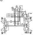
- einen schematischen Schaltplan eines Bremssystems eines Zugfahrzeugs einer Zugfahrzeug-Anhänger-Kombination beinhaltend eine elektrische Feststellbremseinrichtung (ECPB) mit einem Parkbremsmodul (PBM) und eine elektrische Betriebsbremseinrichtung (EBS) mit einem Anhängersteuermodul (TCM) und;
- Fig.2
- einen schematischen Schaltplan des Parkbremsmoduls (PBM) von
Fig.1 ; - Fig.3
- einen schematischen Schaltplan des Anhängersteuermoduls (TCM) von
Fig.1 .
- Fig.1
- a schematic circuit diagram of a brake system of a towing vehicle of a tractor-trailer combination comprising an electric parking brake device (ECPB) with a parking brake module (PBM) and an electric service brake device (EBS) with a trailer control module (TCM) and;
- Fig.2
- a schematic circuit diagram of the parking brake module (PBM) of
Fig.1 ; - Figure 3
- a schematic diagram of the trailer control module (TCM) of
Fig.1 ,
Das in
- Einen
Druckluftvorrat 1, - eine
pneumatische Steuerleitung 2, welche von einem Fußbremsmodul (FBM) 14 zu einem Anhängersteuermodul (TCM) 9 führt, - ein Parkbremsmodul (PBM) 3,
elektrische Steuerleitungen 4 für das Parkbremsmodul (PBM) 3,- eine
Handbetätigungseinrichtung 5 für das Parkbremsmodul (PBM) 3, - eine
pneumatische Steuerleitung 6 zwischen dem Parkbremsmodul (PBM) 3 und dem Anhängersteuermodul (TCM) 9, pneumatische Steuerleitungen 7 zwischen dem Parkbremsmodul (PBM) 3 undFederspeicherbremszylindern 10 der Hinterachse,pneumatische Vorratsleitungen 8 zwischen demDruckluftvorrat 1 und dem Parkbremsmodul (PBM) 3 bzw. dem Anhängersteuermodul (TCM) 9,- das Anhängersteuermodul (TCM) 9,
- die
Federspeicherbremszylinder 10 der Hinterachse, - einen
Druckluftvorrat 11, - einen
Druckluftvorrat 12, - eine pneumatische Vorratsleitung 13 vom
Druckluftvorrat 11 zumFußbremsmodul 14, - eine
pneumatische Vorratsleitung 13a vomDruckluftvorrat 12 zumFußbremsmodul 14, - das
Fußbremsmodul 14, - eine pneumatische Steuerleitung 15 zwischen dem
Fußbremsmodul 14 und einem einkanaligen Vorderachs-Druckregelmodul 19, - eine pneumatische Steuerleitung 16 zwischen dem
Fußbremsmodul 14 und einem zweikanaligen Hinterachs-Druckregelmodul 23, - eine
pneumatische Vorratsleitung 17 zwischen demDruckluftvorrat 11 und dem Vorderachs-Druckregelmodul 19, - eine
pneumatische Vorratsleitung 18 zwischen demDruckluftvorrat 12 und dem Hinterachs-Druckregelmodul 23, - das Vorderachs-
Druckregelmodul 19, Druckleitungen 20 zwischen dem Vorderachs-Druckregelmodul 19 und Drucksteuerventilen 21,Drucksteuerventile 21 für die ABS-Funktion der Vorderachse, z.B. select-low, select-high oder select-smart,Betriebsbremszylinder 22 der Vorderachse,- das zweikanalige Druckregelmodul 23 der Hinterachse,
- ein Steuergerät (ECU) 24 des elektronischen Bremssystems (EBS),
elektrische Steuerleitungen 25 zwischen dem Steuergerät (ECU) 24 des elektronischen Bremssystems (EBS) und dem Anhängersteuermodul (TCM) 9,elektrische Steuerleitungen 26 zwischen dem Steuergerät (ECU) 24 des elektronischen Bremssystems (EBS) undden Drucksteuerventilen 21 der Vorderachse,- elektrische Energieversorgungsleitungen und CAN-
Datenbus 27 zwischen dem Steuergerät (ECU) 24 des elektronischen Bremssystems (EBS)und dem Druckregelmodul 19 der Vorderachse, - elektrische Energieversorgungsleitungen und CAN-
Datenbus 28 zwischen dem Steuergerät (ECU) 24 des elektronischen Bremssystems (EBS) und dem Druckregelmodul 23 der Hinterachse, Sensorkabel 29,Radgeschwindigkeitssensoren 30,Bremsdruckleitungen 31 zwischenden Drucksteuerventilen 19 undden Betriebsbremszylindern 22 der Vorderachse bzw. zwischen dem Druckregelmodul 23 undden Federspeicherbremszylindern 10 der Hinterachse,- CAN (Control Area Network) -
Datenbusleitungen 33, z.B. J1939.
- A
compressed air supply 1, - a
pneumatic control line 2 leading from a foot brake module (FBM) 14 to a trailer control module (TCM) 9, - a parking brake module (PBM) 3,
-
electric control lines 4 for the parking brake module (PBM) 3, - a
manual override device 5 for the parking brake module (PBM) 3, - a
pneumatic control line 6 between the parking brake module (PBM) 3 and the trailer control module (TCM) 9, -
pneumatic control lines 7 between the parking brake module (PBM) 3 andspring brake cylinders 10 of the rear axle, -
pneumatic supply lines 8 between thecompressed air supply 1 and the parking brake module (PBM) 3 and the trailer control module (TCM) 9, - the trailer control module (TCM) 9,
- the
spring brake cylinders 10 of the rear axle, - a
compressed air reservoir 11, - a
compressed air reservoir 12, - a pneumatic supply line 13 from the
compressed air supply 11 to thefoot brake module 14, - a
pneumatic supply line 13a from thecompressed air reservoir 12 to thefoot brake module 14, - the
foot brake module 14, - a pneumatic control line 15 between the
foot brake module 14 and a single-channel front axlepressure control module 19, - a pneumatic control line 16 between the
foot brake module 14 and a two-channel rear axle pressure control module 23, - a
pneumatic supply line 17 between thecompressed air reservoir 11 and the front axlepressure control module 19, - a
pneumatic supply line 18 between thecompressed air reservoir 12 and the rear axle pressure control module 23, - the front axle
pressure control module 19, -
Pressure pipes 20 between the front axlepressure control module 19 andpressure control valves 21, -
Pressure control valves 21 for the ABS function of the front axle, eg select-low, select-high or select-smart, -
Service brake cylinder 22 of the front axle, - the dual-channel pressure control module 23 of the rear axle,
- a control unit (ECU) 24 of the electronic brake system (EBS),
-
electrical control lines 25 between the Electronic Braking System (EBS) control unit (ECU) 24 and the Trailer Control Module (TCM) 9, -
electric control lines 26 between the electronic brake system (ECU) control unit (ECU) 24 and the front axlepressure control valves 21; - electric power supply lines and CAN
data bus 27 between the electronic brake system (ECU) control unit (ECU) 24 and the front axlepressure control module 19; - electric power supply lines and CAN
data bus 28 between the electronic brake system (ECU) control unit (ECU) 24 and the rear axle pressure control module 23; -
Sensor cable 29, -
Wheel speed sensors 30, - Brake pressure lines 31 between the
pressure control valves 19 and theservice brake cylinders 22 of the front axle or between the pressure control module 23 and thespring brake cylinders 10 of the rear axle, - CAN (Control Area Network)
data bus lines 33, eg J1939.
An der Hinterachse des Zugfahrzeugs sind neben den Federspeicherbremszylindern 10 auch Betriebsbremszylinder vorhanden, in
Der Aufbau des Fußbremsmoduls (FBM) 14 für eine elektrische Betriebsbremseinrichtung EBS ist ähnlich den konventionellen rein pneumatischen Fußbremsventilen (FBV). Zusätzlich werden im Fußbremsmodul (FBM) 14 jedoch die elektronischen Sollwerte für die Bremskraftregelung erfasst. Das Fußbremsmodul (FBM) 14 erfüllt somit zwei Aufgaben.
- Zwei redundante Sensoren (z.B. Potentiometer) erfassen den Bremswunsch des Fahrers, indem sie den Betätigungsweg eines FBM-Stößels messen. Der Messwert wird redundant an das zentrale Steuergerät EBS-ECU 24 übertragen und dort in eine Bremsanforderung umgerechnet.
- Analog zu einem konventionellen Fußbremsventil FBV wird der pneumatische Steuerungsdruck entsprechend des Betätigungsweges ausgesteuert. Diese Steuerdrücke werden für die Backup-Steuerung für den Fall eines Fehlers in der elektrischen Betriebsbremseinrichtung EBS benötigt.
- Two redundant sensors (eg potentiometers) detect the driver's braking request by measuring the actuating travel of an FBM plunger. The measured value is transmitted redundantly to the central control unit EBS-ECU 24 and converted there into a braking request.
- Analogous to a conventional foot brake valve FBV, the pneumatic control pressure is controlled according to the actuation travel. These control pressures are needed for backup control in the event of a fault in the electrical service brake EBS.
Die Druckregelmodule 19, 23 bilden die Schnittstelle zwischen der elektrischen Betriebsbremseinrichtung EBS und der pneumatischen Bremskraft. Sie setzen die über den Datenbus CAN J1939 übertragenen Bremssolldrücke in pneumatische Drücke um. Die Umsetzung erfolgt mit Proportionalmagneten oder mit einer Ein-/Auslassmagnetkombination. Ein Drucksensor misst den ausgesteuerten Bremsdruck. Somit kann eine Bremsdruckregelung in einem geschlossenen Regelkreis stattfinden. Ein elektrisch aktiviertes Backup-Magnetventil sperrt die pneumatischen Steuerdrücke des Fußbremsmoduls FBM 14 ab, um eine nicht beeinflusste elektrische Druckregelung zu ermöglichen.The
Die Installation der Druckregelmodule 19, 23 in Radnähe ermöglicht den Anschluss der Sensoren 30 für die Radgeschwindigkeit und den Bremsbelagverschleiß über kurze elektrische Leitungen. Diese Signale werden über den Datenbus CAN J1939 zum zentralen Steuergerät EBS-ECU 24 übertragen.The installation of the
Das elektronische Anhängersteuermodul TCM 9 ermöglicht die Regelung des Anhängersteuerdrucks entsprechend der funktionalen Anforderungen der elektrischen Betriebsbremseinrichtung EBS. Die Grenzen der elektrischen Regelbereiche sind in gesetzlichen Anforderungen festgelegt. Das Umsetzen des elektronisch vorgegebenen Sollwertes in einen ausgesteuerten Druck erfolgt mit einer ähnlichen Magnetanordnung wie in den Druckregelmoduln 19, 23. Das Sperren des back-up-Drucks erfolgt je nach Konstruktionsprinzip über ein Back-up-Magnetventil BV (siehe
Das Ansteuern des Anhängersteuermoduls TCM 9 muss unter allen Normalbedingungen mit zwei unabhängigen Steuersignalen erfolgen. Dies können zwei pneumatische Signale aus zwei Steuerkreisen oder ein pneumatisches und ein elektrisches Steuersignal sein. Das elektrische Steuersignal muss in diesem Fall jedoch unter allen regulären Betriebszuständen zur Verfügung stehen.The control of the trailer control module TCM 9 must be carried out under all normal conditions with two independent control signals. These can be two pneumatic signals from two control circuits or a pneumatic and an electrical control signal. However, in this case, the electrical control signal must be available under all normal operating conditions.
Das Betätigen des Fußbremsmoduls FBM 14 führt zu einer Berechnung des Bremswunsches im zentralen Steuergerät EBS-ECU 24. Gleichzeitig werden die Back-up-Magnetventile in den Druckregelmoduln 19, 23 aktiviert und die pneumatischen Steuerdrücke abgesperrt. Das elektronische Steuergerät EBS-ECU 24 berechnet nun abhängig von Abbremsungswunsch, Fahrzeugmasse, Achslastverteilung usw. den optimalen Bremsdruck. Dieser Sollbremsdruck wird über den Datenbus CAN J1939 an die Druckregelmoduln 19, 23 übertragen.The actuation of the foot
Entsprechend der Anordnung steuern die Druckregelmoduln 19, 23 den Bremsdruck achs- oder radweise in die Bremszylinder 22 ein. Über einen CAN ISO 11992 wird ein dem Anhängersteuerdruck entsprechender Abbremsungswunsch an die elektrische Betriebsbremseinrichtung EBS des Anhängers übermittelt.According to the arrangement, the
Für Funktionen wie ASR (Antriebsschlupfregelung) oder ESP (Elektronisches Stabilitäts-Programm) wird unabhängig vom Fahrerwunsch Bremsdruck in den Druckregelmoduln 19, 23 aufgebaut und in die Bremszylinder 22 eingeregelt.For functions such as ASR (traction control system) or ESP (Electronic Stability Program), independent of the driver's request, brake pressure is built up in the
Das Parkbremsmodul (PBM) 3 beinhaltet gemäß
ein Relaisventilteil 34, das abhängig vom Druck in seiner Steuerkammer einen Druck in seiner Arbeitskammer einregelt, welcher an einemAnschluss port 21 desParkbremsmoduls 3 ansteht, der über die pneumatischen Steuerleitungen 7 (sieheFig.1 )mit den Federspeicherzylindern 10 der Hinterachse in Verbindung steht,einen Drucksensor 36, der den Druck in der Arbeitskammer des Relaisventils 34 misst,- ein bistabiles 3/2-Wege-
Magnetventil 37 zum permanenten Be- oder Entlüften der Steuerkammer des Relaisventils 34, ein 2/2-Wege-Magnetventil 38 zum Halten des Drucks in der Steuerkammer des Relaisventils 34,ein 3/2-Wege-Magnetventil 39 (Testmagnet) zum Durchsteuern des Drucks in der Arbeitskammer des Relaisventils 34 oder eines aneinem Vorratsanschluss port 1 anstehenden Vorratsdrucks zu einem Anhängeranschlussport 22,- ein Steuergerät ECPB-ECU 40 der Feststellbremseinrichtung ECPB, welches die
Ventile
- a
relay valve member 34 which regulates a pressure in its working chamber depending on the pressure in its control chamber, which is present at aport 21 of theparking brake module 3, via the pneumatic control lines 7 (seeFig.1 ) is in communication with the spring-loadedcylinders 10 of the rear axle, - a
pressure sensor 36 which measures the pressure in the working chamber of therelay valve 34, - a bistable 3/2-
way solenoid valve 37 for permanently venting the control chamber of therelay valve 34, - a 2/2-
way solenoid valve 38 for holding the pressure in the control chamber of therelay valve 34, - a 3/2-way solenoid valve 39 (test magnet) for controlling the pressure in the working chamber of the
relay valve 34 or asupply port 1 at a supply port supply pressure to atrailer port 22, - a control unit ECPB-ECU 40 of the parking brake device ECPB, which controls the
valves pressure sensor 36 and is connected to the vehicle data bus CAN J1939.
Das Anhängersteuermodul TCM 9 gemäß
- ein dreifach angesteuertes Relaisventil RLV,
- ein Backup-Ventil BV,
- ein Einlassventil IV,
- ein Auslassventil OV,
- ein Drosselventil DV,
- einen Drucksensor PS zur Messung des Drucks in der Anhängerbremsleitung, welche an einen
Anschluss port 22 angeschlossen ist, der zu einem Kupplungskopf "Bremse" des Zugfahrzeugs führt und den Anhänger mit Steuerdruck für die Anhängerbremse versorgt, - einen
Anschluss port 21, der zu einem Kupplungskopf "Vorrat" des Zugfahrzeugs führt und den Anhänger mit Vorratsdruck versorgt, - einen
Anschluss port 43, an welchen derport 22 des Parkbremsmoduls (PBM) 3 (Fig.2 ) über die pneumatische Steuerleitung 6 angeschlossen ist, - einen
Anschluss port 42, an welchen die vom Fußbremsmodul (FBM) 14 herangeführte pneumatische Steuerleitung 2 angeschlossen ist und in welchen der pneumatische Steuerdruck des Fußbremsmoduls (FBM) 14 eingesteuert wird, - einen
Anschluss port 1, an welchen der Druckluftvorrat 1 angeschlossen ist, - eine Entlüftung SD, welche an das Auslassventil OV angeschlossen ist.
- a triple-actuated relay valve RLV,
- a backup valve BV,
- an inlet valve IV,
- an outlet valve OV,
- a throttle valve DV,
- a pressure sensor PS for measuring the pressure in the trailer brake line, which is connected to a
terminal port 22, which leads to a coupling head "brake" of the towing vehicle and supplies the trailer with control pressure for the trailer brake, - a
connection port 21, which leads to a coupling head "supply" of the towing vehicle and supplies the trailer with supply pressure, - a
port 43 to which theport 22 of the parking brake module (PBM) 3 (Fig.2 ) is connected via thepneumatic control line 6, - a
port 42, to which the foot brake module (FBM) 14 zoom introducedpneumatic control line 2 is connected and in which the pneumatic control pressure of the foot brake module (FBM) 14 is controlled, - a
port 1 to which thecompressed air supply 1 is connected, - a vent SD, which is connected to the outlet valve OV.
Die Ventile BV, IV, OV des Anhängersteuermoduls (TCM) 9 werden vom Steuergerät EBS-ECU 24 der elektrischen Betriebsbremseinrichtung (EBS) angesteuert, welches wiederum mit dem Datenbus CAN J1939 in Kommunikationsverbindung steht.The valves BV, IV, OV of the trailer control module (TCM) 9 are controlled by the control unit EBS-ECU 24 of the electrical service brake device (EBS), which in turn is in communication with the data bus CAN J1939.
In dem Zugfahrzeug sind folglich das Steuergerät ECPB-ECU 40 (siehe
Wenn der Fahrer die Feststellbremse durch Betätigung der Handbetätigungseinrichtung 5 einlegt, muss die vom port 22 des Parkbremsmoduls PBM 3 (
Über den CAN-Datenbus J1939 als Kommunikationsverbindung zwischen der EBS-ECU 24 als Steuergerät der elektrischen Betriebsbremseinrichtung EBS und der ECPB-ECU 40 als Steuergerät der Feststellbremseinrichtung ECPB kann die ECPB-ECU 40 der Feststellbremseinrichtung ECPB den Druck an port 22 des Anhängersteuermoduls TCM 9 abfragen. Wird dieser Druck am port 22 des Anhängersteuermoduls TCM 9 nicht aufgebaut, so ist die Feststellbrems-Funktion fehlerhaft oder der Vorratsdruck an port 1 des Feststellbremsmoduls PBM 3 oder an port 1 des Anhängersteuermoduls TCM 9 zu gering.The ECPB-ECU 40 of the parking brake device ECPB can query the pressure on
Unter der Voraussetzung, dass die Entlüftung der Federspeicherbremszylinder 10 im Zugfahrzeug erfolgreich war, sind folgende Fehler möglich :
- 1. Es ist kein
Vorratsdruck am port 1 des Anhängersteuermoduls TCM 9 vorhanden.- Der über den Datenbus CAN J1939 an die ECPB-ECU 40 übermittelte Wert für den Vorratsdruck ist Null.
- Es erfolgt jedoch keine Fehleranzeige, da ein Fehler in der Druckluftversorgung auch als normaler Betriebszustand vorliegen kann, wenn beispielsweise der Druckluftvorrat noch nicht befüllt ist.
- Es wird keine Rückfallebene (back-up) eingenommen, da der Zustand der Druckluftversorgung weder vom elektronischen Betriebsbremssystem EBS noch von der Feststellbremseinrichtung ECPB beeinflussbar ist. Da jedoch auch die Vorratsleitung zum Anhänger (
port 21 des Anhängersteuermoduls TCM 9) entlüftet ist, bremst der Anhänger über die Abreißfunktion automatisch ein.
- 2.
Das 3/2-Wege-Magnetventil 39 (Testmagnet)im Parkbremsmodul PBM 3 wird fälschlicherweise bestromt, beispielsweise aufgrund eines Fehler in der ECPB-ECU 40.- Der CAN J1939 Datenbus meldet einen ausreichenden Vorratsdruck. Es erfolgt eine Ventilrückmeldeprüfung durch die ECPB-ECU 40 im Rahmen der Eigenüberwachungsroutinen.
- Es erfolgt keine Fehleranzeige durch die EBS-ECU 24, da der Fehler in der Feststellbremseinrichtung ECPB liegt, jedoch erfolgt eine Fehlermeldung durch die ECPB-ECU 40, z.B.: "
Ventilrückmeldefehler im 3/2-Wege-Magnetventil 39". - Als Rückfallebene sendet die ECPB-ECU 40 einen Befehl an die EBS-ECU 24, den Druck zum Anhänger elektrisch einzusteuern.
- 3. Die Vorratsleitung (
port 1 an TCM 9) zum Anhängersteuermodul TCM 9 ist gerissen oder verstopft.- der CAN J1939 Datenbus meldet einen ausreichenden Vorratsdruck. Die ECPB-ECU 40 sendet einen Befehl an die EBS-ECU 24, den Druck zum Anhänger elektrisch einzusteuern. Gelingt dies nicht, wird die EBS-ECU 24 nach einiger Zeit erkennen, dass keine Belüftung der Steuerleitung (port 22) zum Anhänger möglich ist, und einen entsprechenden Fehler setzen.
- Durch die ECPB-ECU 40 erfolgt keine Fehleranzeige, da der Fehler in der Betriebsbremseinrichtung EBS vorliegt, wobei die EBS-ECU 24 "Fehler in der Vorratsleitung (port 1) zum Anhängersteuermodul TCM 9" meldet.
- Es existiert keine Rückfallebene, da weder die Betriebsbremseinrichtung EBS noch die Feststellbremseinrichtung ECPB eine Eingriffsmöglichkeit hat. Da jedoch auch die Vorratsleitung (port 21) zum Anhänger entlüftet ist, bremst der Anhänger über die Abreißfunktion automatisch ein.
- 4.
Das 3/2-Wege-Magnetventil 39 (Testmagnet) klemmt mechanisch oder dieLeitung zum port 43 des Anhängersteuermoduls TCM 9 ist verstopft.- Dies wird erkannt, weil keiner der anderen Fehler vorliegt.
- Es erfolgt eine Fehleranzeige durch die ECPB-ECU 40 wie z.B. "
Leitung zum port 43 des Anhängersteuermoduls TCM 9ist verstopft oder 3/2-Wege-Magnetventil (Testmagnet) 39 ist mechanisch defekt". Durch die EBS-ECU 24 erfolgt keine Fehlermeldung, da der Fehler im Bereich der Feststellbremseinrichtung ECPB aufgetreten ist. - Als Rückfallebene sendet die ECPB-ECU 40 den Befehl an die EBS-ECU 24, den Druck zum Anhänger elektrisch einzusteuern.
- 1. There is no supply pressure at
port 1 of the trailer control module TCM 9.- The value for the supply pressure transmitted via the data bus CAN J1939 to the ECPB-ECU 40 is zero.
- However, there is no error indication, since a fault in the compressed air supply can also be present as a normal operating state, if, for example, the compressed air reservoir is not yet filled.
- There is no fallback (back-up) assumed, since the state of the compressed air supply can be influenced neither by the electronic service brake system EBS nor by the parking brake ECPB. However, since the supply line to the trailer (
port 21 of the trailer control module TCM 9) is vented, the trailer automatically brakes using the tear-off function.
- 2. The 3/2-way solenoid valve 39 (test magnet) in the parking
brake module PBM 3 is erroneously energized, for example due to a fault in the ECPB-ECU 40.- The CAN J1939 data bus reports sufficient supply pressure. A valve feedback check is performed by the ECPB-ECU 40 as part of the self-monitoring routines.
- There is no error indication by the EBS-ECU 24 because the fault is in the parking brake device ECPB, but an error message is issued by the ECPB-ECU 40, eg: "Valve feedback error in the 3/2-
way solenoid valve 39". - As a fallback level, the ECPB-ECU 40 sends a command to the EBS-ECU 24 to control the pressure to the trailer electrically.
- 3. The supply line (
port 1 to TCM 9) to the trailer control module TCM 9 is cracked or clogged.- The CAN J1939 data bus reports sufficient supply pressure. The ECPB-ECU 40 sends a command to the EBS-ECU 24 to control the pressure to the trailer electrically. If this does not succeed, the EBS-ECU 24 will eventually realize that no venting of the control line (port 22) to the trailer is possible and make a corresponding error.
- No error indication is given by the ECPB-ECU 40 because the fault is present in the service brake device EBS, the EBS-ECU 24 "Fault in the supply line (port 1) to the trailer control module TCM 9" reports.
- There is no fallback level, since neither the service brake device EBS nor the parking brake device ECPB has a possibility of intervention. However, since the supply line (port 21) to the trailer is vented, the trailer automatically brakes via the tear-off function.
- 4. The 3/2-way solenoid valve 39 (test solenoid) jams mechanically or the line to the
port 43 of the trailer control module TCM 9 is clogged.- This is detected because none of the other errors exist.
- An error message is displayed by the ECPB-ECU 40 such as "Line to
port 43 of the trailer control module TCM 9 is blocked or 3/2-way solenoid valve (test magnet) 39 is mechanically defective". The EBS-ECU 24 does not issue an error message because the error has occurred in the area of the parking brake device ECPB. - As a fallback level, the ECPB-ECU 40 sends the command to the EBS-ECU 24 to control the pressure to the trailer electrically.
Ohne die Abfrage des Anhängerdrucks an port 22 des Parkbremsmoduls PBM 3 bzw. an port 43 des Anhängersteuermoduls 9 wäre der Fehler nicht erkannt worden. Durch den Einsatz der elektrischen, mittels der EBS-ECU 24 gesteuerten Aktuatoren können nach der Erkennung des Fehlers die möglichen Ursachen besser eingegrenzt werden und beim Vorliegen gestimmter Ursachen eventuell eine Backup-Funktion über die EBS-ECU 24 aktiviert werden.Without the query of the trailer pressure on
Die einen Fehler oder eine Störung in der elektrischen Feststellbremseinrichtung ECPB im Rahmen einer Selbstüberwachung detektierenden Sensoren beinhalten folglich den Drucksensor 36 im Parkbremsmodul PBM 3 sowie die Magnetventile 34, 37, 38 und 39 im Parkbremsmodul PBM 3 zur Druckregelung am port 22 und zum Ausführen der Testfunktion.The sensors detecting a fault or fault in the electric parking brake device ECPB as part of a self-monitoring consequently include the
Der elektrischen Betriebsbremseinrichtung EBS zugeordnete Sensoren und Aktuatoren, welche den Fehler oder die Störung in wenigstens einer Funktion der elektrischen Feststellbremseinrichtung ECPB erkennen und/oder eingrenzen und/oder ein Notlaufprogramm der elektrischen Betriebsbremseinrichtung EBS als Ersatz für die gestörte Funktion der elektrischen Feststellbremseinrichtung ECPB aktivieren, beinhalten einen Drucksensor im Anhängersteuermodul TCM 9 als Sensor und die Magnetventile im Anhängersteuermodul TCM 9 zur Druckregelung als Aktuatoren.Sensors and actuators associated with the electrical service brake device EBS, which detect and / or limit the fault or malfunction in at least one function of the electric parking brake device ECPB and / or activate an emergency operation program of the electric service brake device EBS as a replacement for the faulty function of the electric parking brake device ECPB a pressure sensor in the trailer control module TCM 9 as a sensor and the solenoid valves in the trailer control module TCM 9 for pressure control as actuators.
- 11
- DruckluftvorratCompressed air supply
- 22
- Steuerleitungcontrol line
- 33
- Parkbremsmodul PBMParking brake module PBM
- 44
- elektrische Steuerleitungenelectrical control lines
- 55
- HandbetätigungseinrichtungManual actuator
- 66
- pneumatische Steuerleitungpneumatic control line
- 77
- pneumatische Steuerleitungenpneumatic control lines
- 88th
- pneumatische Vorratsleitungenpneumatic supply lines
- 99
- Anhängersteuermodul TCMTrailer control module TCM
- 1010
- FederspeicherbremszylinderSpring brake cylinder
- 1111
- DruckluftvorratCompressed air supply
- 1212
- DruckluftvorratCompressed air supply
- 1313
- pneumatische Vorratsleitungpneumatic supply line
- 13a13a
- pneumatische Vorratsleitungpneumatic supply line
- 1414
- Fußbremsmodulfoot brake
- 1515
- pneumatische Steuerleitungpneumatic control line
- 1616
- pneumatische Steuerleitungpneumatic control line
- 1717
- pneumatische Vorratsleitungpneumatic supply line
- 1818
- pneumatische Vorratsleitungpneumatic supply line
- 1919
- Vorderachs-DruckregelmodulFront axle pressure control module
- 2020
- Druckleitungenpressure lines
- 2121
- DrucksteuerventilePressure control valves
- 2222
- BetriebsbremszylinderService brake cylinder
- 2323
- DruckregelmodulPressure control module
- 2424
- Steuergerät (ECU) des elektronischen Bremssystems (EBS)Electronic braking system (ECU) control unit (ECU)
- 2525
- elektrische Steuerleitungenelectrical control lines
- 2626
- elektrische Steuerleitungenelectrical control lines
- 2727
- elektrische Energieversorgungsleitungen und CAN-Datenbuselectrical power supply lines and CAN data bus
- 2828
- elektrische Energieversorgungsleitungen und CAN-Datenbuselectrical power supply lines and CAN data bus
- 2929
- Sensorkabelsensor cable
- 3030
- Radgeschwindigkeitssensorenwheel speed sensors
- 3131
- BremsdruckleitungenBrake pressure lines
- 3333
- CAN (Control Area Network) -DatenbusleitungenCAN (Control Area Network) data bus lines
- 3434
- RelaisventilteilRelay valve part
- 3636
- Drucksensorpressure sensor
- 3737
- bistabiles 3/2-Wege-Magnetventilbistable 3/2-way solenoid valve
- 3838
- 2/2-Wege-Magnetventil2/2-way solenoid valve
- 3939
- 3/2-Wege-Magnetventil (Testmagnet)3/2-way solenoid valve (test magnet)
- 4040
- ECPB-ECUECPB ECU
Claims (5)
- Monitoring system for monitoring systems of a vehicle, whereof at least some systems include self-monitoring routines for self-monitoring and/or some systems include external monitoring routines for external monitoring of other systems, which are not provided for the system's own functions or for self-monitoring, characterized in that when a malfunction or a fault is detected in at least one function associated with a first one of said systems (ECPB) by self-monitoring routines of said first system (ECPB) a second system (EBS) is activated by said first system (ECPB) including said fault or said malfunction or by external monitoring routines of a third system monitoring said one first system (ECPB), in order to detect and/or further pinpoint said fault or said malfunction in said at least one function of said first system (ECPB) by means of actuators and/or sensors associated with said second system (EBS), and/or in order to activate an emergency running programme of said second system (EBS) as substitute for the malfunction function of said first system.
- Monitoring system according to Claim 1, characterized in that said self-monitoring routines and/or said external monitoring routines recognise a fault or a malfunction of said at least one function of said first system (ECPB) by the type of the signals adjusted by said first system (ECPB) and/or by the non-appearance of signals adjusted by said first system (ECPB).
- Monitoring system according to any of the preceding Claims, characterized in that said first system is an electric parking brake means (ECPB) whilst said second system is an electrical service brake means (EBS) of a tractor, vehicle in a tractor-trailer combination.
- Monitoring system according to Claim 3, characterized in that the sensors associated with said electrical service brake means (EBS) include at least one pressure sensor of a trailer control module (TCM, 9) whilst the actuators associated with said electrical service brake means (EBS) include solenoid-controlled valves of said trailer control module (TCM 9) for pressure control.
- Monitoring system according to Claim 3 or 4, characterized in that the sensors detecting a fault or a malfunction in said electrical parking brake means (ECPB) within the general framework of the self-monitoring function include at least one pressure sensor (36) of a parking brake module (PBM, 3) as well as solenoid-controlled valves (34, 37, 38) of said parking brake module (PBM 3) for pressure control.
Applications Claiming Priority (2)
| Application Number | Priority Date | Filing Date | Title |
|---|---|---|---|
| DE102008029310.5A DE102008029310C5 (en) | 2008-06-20 | 2008-06-20 | Monitoring device for monitoring systems of a vehicle |
| PCT/EP2009/004161 WO2009152982A2 (en) | 2008-06-20 | 2009-06-10 | Monitoring device for monitoring vehicle systems |
Publications (3)
| Publication Number | Publication Date |
|---|---|
| EP2288523A2 EP2288523A2 (en) | 2011-03-02 |
| EP2288523B1 true EP2288523B1 (en) | 2012-04-25 |
| EP2288523B2 EP2288523B2 (en) | 2018-08-29 |
Family
ID=41412480
Family Applications (1)
| Application Number | Title | Priority Date | Filing Date |
|---|---|---|---|
| EP09765562.5A Active EP2288523B2 (en) | 2008-06-20 | 2009-06-10 | Monitoring device for monitoring vehicle systems |
Country Status (7)
| Country | Link |
|---|---|
| US (1) | US8560162B2 (en) |
| EP (1) | EP2288523B2 (en) |
| JP (1) | JP5456030B2 (en) |
| AT (1) | ATE554978T1 (en) |
| DE (1) | DE102008029310C5 (en) |
| RU (1) | RU2520268C2 (en) |
| WO (1) | WO2009152982A2 (en) |
Families Citing this family (38)
| Publication number | Priority date | Publication date | Assignee | Title |
|---|---|---|---|---|
| DE102010021909A1 (en) | 2010-05-28 | 2011-12-01 | Knorr-Bremse Systeme für Nutzfahrzeuge GmbH | Method for controlling a brake system of a vehicle with electronically controlled Hinterachsbremskreis and pneumatically controlled Vorderachsbremskreis |
| DE102011011634B4 (en) * | 2011-02-17 | 2012-12-06 | Knorr-Bremse Systeme für Nutzfahrzeuge GmbH | Compressed air supply device for commercial vehicles |
| DE102011004995A1 (en) * | 2011-03-02 | 2012-09-06 | Jungheinrich Aktiengesellschaft | Vehicle, in particular industrial truck |
| EP2570316B2 (en) | 2011-09-16 | 2022-10-26 | Haldex Brake Products GmbH | Operating system for a commercial vehicle |
| CN104067031B (en) | 2012-01-25 | 2016-05-04 | 克朗设备公司 | Be used for the system and method for the functional status of monitoring materials handling vehicle |
| US9381895B1 (en) * | 2012-12-07 | 2016-07-05 | Randall H. SMATHERS | Parking brake safety system |
| CN103009960B (en) * | 2012-12-26 | 2015-02-04 | 潍柴动力股份有限公司 | Monitoring equipment and method for electric air compression system of electric vehicle |
| US20150081159A1 (en) * | 2013-09-17 | 2015-03-19 | Hyundai Motor Company | Apparatus and method of sensing and controlling wear of brake lining |
| DE102013016877B3 (en) * | 2013-10-11 | 2014-10-09 | Knorr-Bremse Systeme für Nutzfahrzeuge GmbH | Method for controlling a pressure control device of a pressure medium brake system of a vehicle |
| DE102014011422A1 (en) * | 2014-07-31 | 2016-02-04 | Wabco Gmbh | Brake pressure modulator of an electronic braking system of a commercial vehicle |
| DE102015001628A1 (en) | 2015-02-07 | 2016-08-11 | Wabco Gmbh | Method for setting brake pressures of a motor vehicle via control of a pressure control valve, brake system for carrying out the method and motor vehicle |
| DE102015106157B4 (en) * | 2015-04-22 | 2022-09-01 | Knorr-Bremse Systeme für Nutzfahrzeuge GmbH | Switching arrangement, in particular for compressed air treatment |
| WO2017017491A1 (en) * | 2015-07-27 | 2017-02-02 | Volvo Truck Corporation | Brake arrangement comprising hybrid brake actuators |
| DE102015112490B4 (en) | 2015-07-30 | 2018-07-19 | Knorr-Bremse Systeme für Nutzfahrzeuge GmbH | Electro-pneumatic control device of an electro-pneumatic brake system of a tractor-trailer combination |
| JP6531740B2 (en) * | 2016-08-24 | 2019-06-19 | 株式会社アドヴィックス | Brake control device |
| DE102017102074A1 (en) * | 2017-02-02 | 2018-08-02 | Knorr-Bremse Systeme für Nutzfahrzeuge GmbH | Interface element for a vehicle |
| DE102017002718A1 (en) * | 2017-03-21 | 2018-09-27 | Wabco Gmbh | Electronically controllable braking system and method for controlling the electronically controllable braking system |
| DE102017002716A1 (en) * | 2017-03-21 | 2018-09-27 | Wabco Gmbh | Electronically controllable braking system and method for controlling the electronically controllable braking system |
| DE102017002719A1 (en) | 2017-03-21 | 2018-09-27 | Wabco Gmbh | Electronically controllable braking system and method for controlling the electronically controllable braking system |
| DE102017006356A1 (en) * | 2017-03-21 | 2018-09-27 | Wabco Gmbh | Electro-pneumatic handbrake (EPH) with integrated TCV (European control) |
| DE102017005979A1 (en) | 2017-03-21 | 2018-09-27 | Wabco Gmbh | Electro-pneumatic handbrake (EPH) with integrated TCV (Scandinavian control |
| US20180273004A1 (en) * | 2017-03-27 | 2018-09-27 | Bendix Commercial Vehicle Systems Llc | Valve system and method for controlling same |
| EP3415386B1 (en) * | 2017-06-16 | 2019-12-11 | KNORR-BREMSE Systeme für Nutzfahrzeuge GmbH | Vehicle brake system |
| DE102018104143A1 (en) * | 2018-02-23 | 2019-08-29 | Wabco Gmbh | Brake system for a vehicle train and tractor equipped therewith |
| EP3787942B1 (en) * | 2018-05-03 | 2022-03-30 | Volvo Truck Corporation | Heavy duty vehicle redundant braking system |
| DE102018118745A1 (en) | 2018-08-02 | 2020-02-06 | Wabco Gmbh | Electro-pneumatic handbrake (EPH) with partially decoupled TCV (European control) |
| EP3626558B1 (en) * | 2018-09-18 | 2022-10-26 | KNORR-BREMSE Systeme für Nutzfahrzeuge GmbH | Brake system for a vehicle |
| EP3626559B1 (en) * | 2018-09-18 | 2022-10-26 | KNORR-BREMSE Systeme für Nutzfahrzeuge GmbH | Brake system for a vehicle |
| EP3626561B1 (en) * | 2018-09-18 | 2020-11-04 | KNORR-BREMSE Systeme für Nutzfahrzeuge GmbH | Redundant brake system for an autonomously driven vehicle |
| KR102141287B1 (en) * | 2018-12-04 | 2020-08-04 | 이화여자대학교 산학협력단 | Fault injection test method and system for vehicle software based on autosar |
| CN109883724B (en) * | 2018-12-28 | 2024-03-26 | 杭州沃镭智能科技股份有限公司 | Performance detection device and detection method for EBS (electronic brake system) double-channel bridge module |
| DE102019103661A1 (en) * | 2019-02-13 | 2020-08-13 | Wabco Europe Bvba | Compressed air brake system of a motor vehicle |
| DE102019106591A1 (en) | 2019-03-15 | 2020-09-17 | Wabco Gmbh | Electronically controllable braking system with two fall-back levels |
| EP3770033B1 (en) * | 2019-07-23 | 2022-04-06 | KNORR-BREMSE Systeme für Nutzfahrzeuge GmbH | Apparatus and method for determining a status of the trailer brake |
| DE102019129305A1 (en) * | 2019-10-30 | 2021-05-06 | Knorr-Bremse Systeme für Nutzfahrzeuge GmbH | Switching device for a brake system for a vehicle, brake system with a switching device and method for operating a switching device |
| ES2916401T3 (en) * | 2019-11-18 | 2022-06-30 | Knorr Bremse Systeme Fuer Nutzfahrzeuge Gmbh | Brake system for an air supply and control module of motor vehicles and trailers |
| DE102020108072A1 (en) * | 2020-03-24 | 2021-09-30 | Knorr-Bremse Systeme für Nutzfahrzeuge GmbH | Electronically controlled service brake system with backup control pressure generated on the basis of another compressed air consumer circuit |
| CN116678645B (en) * | 2023-07-28 | 2023-10-03 | 烟台市劲拓汽车科技有限公司 | Automobile hand brake detection device |
Family Cites Families (21)
| Publication number | Priority date | Publication date | Assignee | Title |
|---|---|---|---|---|
| SU854785A1 (en) * | 1979-04-24 | 1981-08-15 | Белорусский Ордена Трудового Красного Знамени Политехнический Институт | Ekectro-pneumatic brake system of a vehicle |
| DE3829949A1 (en) * | 1988-09-03 | 1990-03-15 | Daimler Benz Ag | METHOD FOR OPERATING AN ELECTRIC PRESSURE OPERATING BRAKE DEVICE AND CONTROL DEVICE FOR CARRYING OUT THE METHOD |
| GB9313218D0 (en) | 1993-06-26 | 1993-08-11 | Lucas Ind Plc | Electronic braking system with system test |
| DE19510522C2 (en) * | 1995-03-23 | 2000-02-03 | Bosch Gmbh Robert | Method and device for controlling or regulating the brake system of a vehicle |
| DE10006656C1 (en) * | 2000-02-15 | 2001-06-07 | Siemens Ag | Electric parking brake for motor vehicle guarantees regulated braking of vehicle by dynamically operating parking brake at low cost |
| JP4528457B2 (en) | 2001-03-15 | 2010-08-18 | 日立オートモティブシステムズ株式会社 | Brake device for automobile and control method thereof |
| DE10201453A1 (en) * | 2001-09-10 | 2003-05-28 | Knorr Bremse Systeme | Method and control system for operating a solenoid valve for pneumatic brake cylinders |
| DE10320608B4 (en) * | 2003-05-08 | 2005-08-11 | Knorr-Bremse Systeme für Nutzfahrzeuge GmbH | Brake system for vehicles, in particular commercial vehicles with at least two separate electronic brake control circuits |
| DE10336611A1 (en) * | 2003-08-08 | 2005-03-03 | Wabco Gmbh & Co.Ohg | Pressure-medium-operated brake system for a vehicle |
| DE10357373B4 (en) | 2003-12-09 | 2006-08-24 | Knorr-Bremse Systeme für Nutzfahrzeuge GmbH | Electronic brake system for a vehicle |
| US7136729B2 (en) * | 2004-07-26 | 2006-11-14 | General Motors Corporation | Supervisory diagnostics for integrated vehicle stability system |
| JP2006044624A (en) | 2004-08-06 | 2006-02-16 | Wabco Gmbh & Co Ohg | Braking system operated by pressure medium for vehicle |
| DE102005024120B4 (en) * | 2005-05-25 | 2009-07-30 | Knorr-Bremse Systeme für Nutzfahrzeuge GmbH | Parking brake device of a vehicle with electro-pneumatic emergency release device |
| JP4661438B2 (en) * | 2005-08-04 | 2011-03-30 | 株式会社デンソー | Vehicle communication system |
| DE102005043608B4 (en) | 2005-09-06 | 2008-01-17 | Knorr-Bremse Systeme für Nutzfahrzeuge GmbH | Method for controlling a pneumatic brake system |
| US7899610B2 (en) * | 2006-10-02 | 2011-03-01 | Inthinc Technology Solutions, Inc. | System and method for reconfiguring an electronic control unit of a motor vehicle to optimize fuel economy |
| DE102006055570B4 (en) | 2006-11-24 | 2010-05-06 | Knorr-Bremse Systeme für Nutzfahrzeuge GmbH | Parking brake device with a parking brake emergency release device |
| DE102007004758C5 (en) † | 2007-01-31 | 2016-07-21 | Knorr-Bremse Systeme für Nutzfahrzeuge GmbH | Brake system and method for controlling a brake system for a commercial vehicle |
| DE102007017668A1 (en) * | 2007-04-14 | 2008-10-16 | Bayerische Motoren Werke Aktiengesellschaft | Charged internal combustion engine and method for monitoring whether the crankcase breather has been connected |
| JP4776610B2 (en) * | 2007-11-26 | 2011-09-21 | 三菱電機株式会社 | On-vehicle electronic control device having a supervisory control circuit |
| DE102008018622B4 (en) † | 2008-04-11 | 2011-07-28 | Knorr-Bremse Systeme für Nutzfahrzeuge GmbH, 80809 | Method for operating a brake system and brake system for a commercial vehicle |
-
2008
- 2008-06-20 DE DE102008029310.5A patent/DE102008029310C5/en active Active
-
2009
- 2009-06-10 EP EP09765562.5A patent/EP2288523B2/en active Active
- 2009-06-10 US US12/737,212 patent/US8560162B2/en not_active Expired - Fee Related
- 2009-06-10 JP JP2011513921A patent/JP5456030B2/en active Active
- 2009-06-10 AT AT09765562T patent/ATE554978T1/en active
- 2009-06-10 WO PCT/EP2009/004161 patent/WO2009152982A2/en active Application Filing
- 2009-06-10 RU RU2011101984/11A patent/RU2520268C2/en active
Also Published As
| Publication number | Publication date |
|---|---|
| WO2009152982A3 (en) | 2010-09-02 |
| ATE554978T1 (en) | 2012-05-15 |
| DE102008029310B4 (en) | 2012-01-26 |
| RU2011101984A (en) | 2012-07-27 |
| WO2009152982A2 (en) | 2009-12-23 |
| JP5456030B2 (en) | 2014-03-26 |
| US20110144855A1 (en) | 2011-06-16 |
| EP2288523A2 (en) | 2011-03-02 |
| US8560162B2 (en) | 2013-10-15 |
| EP2288523B2 (en) | 2018-08-29 |
| RU2520268C2 (en) | 2014-06-20 |
| DE102008029310C5 (en) | 2019-01-03 |
| JP2011524299A (en) | 2011-09-01 |
| DE102008029310A1 (en) | 2010-01-14 |
Similar Documents
| Publication | Publication Date | Title |
|---|---|---|
| EP2288523B1 (en) | Monitoring device for monitoring vehicle systems | |
| DE102008009043B3 (en) | Electronically controlled braking system with redundant control of the brake actuators | |
| EP2176105B1 (en) | Control device for a brake system of a utility vehicle, and method for controlling a brake system | |
| EP0187901B1 (en) | Electrically controlled brake installation for vehicles | |
| DE102014107399B4 (en) | Electronically controlled, electro-pneumatic brake system | |
| EP2078650B1 (en) | Braking system for a vehicle | |
| WO2020187569A1 (en) | Electronically controllable braking system having two fall-back levels | |
| EP3317149B1 (en) | Electric brake device with parking brake which can be activated by the service brake-actuating element | |
| WO2007065498A1 (en) | Electro-pneumatic brake control device | |
| EP2298616B2 (en) | Control device and method for testing a valve device of an electric parking brake | |
| DE102008003379A1 (en) | Brake system for a vehicle and brake pedal device for such a brake system | |
| WO2019158351A1 (en) | Electropneumatic equipment of a vehicle | |
| WO1997003871A1 (en) | Brake control device for composite vehicles | |
| EP3650292B1 (en) | Method for checking the operation of an electronic braking system of a vehicle controlled with compressed agent | |
| EP4069559A1 (en) | Monostable and fault-tolerant parking brake valve assembly | |
| DE4132767C2 (en) | Method for diagnosing an electronically controlled pressure medium braking device of a vehicle | |
| DE2723847B2 (en) | Monitoring device for an anti-lock vehicle brake system | |
| EP0442050B1 (en) | Electronically controlled pressure means brake installation | |
| EP2025569B1 (en) | Auxiliary brake for commercial vehicles | |
| DE102018120350A1 (en) | Electropneumatic parking brake arrangement with shut-off valve | |
| DE102022134255B3 (en) | Electro-pneumatic service braking device for a vehicle | |
| WO2023285559A1 (en) | Method for checking functioning of a pressure medium-operated electronic brake system of a vehicle | |
| DE102022117667A1 (en) | Method for determining a brake pressure and pressure-operated braking device |
Legal Events
| Date | Code | Title | Description |
|---|---|---|---|
| PUAI | Public reference made under article 153(3) epc to a published international application that has entered the european phase |
Free format text: ORIGINAL CODE: 0009012 |
|
| AK | Designated contracting states |
Kind code of ref document: A2 Designated state(s): AT BE BG CH CY CZ DE DK EE ES FI FR GB GR HR HU IE IS IT LI LT LU LV MC MK MT NL NO PL PT RO SE SI SK TR |
|
| AX | Request for extension of the european patent |
Extension state: AL BA RS |
|
| 17P | Request for examination filed |
Effective date: 20110302 |
|
| RBV | Designated contracting states (corrected) |
Designated state(s): AT BE BG CH CY CZ DE DK EE ES FI FR GB GR HR HU IE IS IT LI LT LU LV MC MK MT NL NO PL PT RO SE SI SK TR |
|
| DAX | Request for extension of the european patent (deleted) | ||
| GRAP | Despatch of communication of intention to grant a patent |
Free format text: ORIGINAL CODE: EPIDOSNIGR1 |
|
| GRAS | Grant fee paid |
Free format text: ORIGINAL CODE: EPIDOSNIGR3 |
|
| GRAA | (expected) grant |
Free format text: ORIGINAL CODE: 0009210 |
|
| AK | Designated contracting states |
Kind code of ref document: B1 Designated state(s): AT BE BG CH CY CZ DE DK EE ES FI FR GB GR HR HU IE IS IT LI LT LU LV MC MK MT NL NO PL PT RO SE SI SK TR |
|
| REG | Reference to a national code |
Ref country code: GB Ref legal event code: FG4D Free format text: NOT ENGLISH |
|
| REG | Reference to a national code |
Ref country code: CH Ref legal event code: EP |
|
| REG | Reference to a national code |
Ref country code: AT Ref legal event code: REF Ref document number: 554978 Country of ref document: AT Kind code of ref document: T Effective date: 20120515 |
|
| REG | Reference to a national code |
Ref country code: IE Ref legal event code: FG4D Free format text: LANGUAGE OF EP DOCUMENT: GERMAN |
|
| REG | Reference to a national code |
Ref country code: DE Ref legal event code: R096 Ref document number: 502009003392 Country of ref document: DE Effective date: 20120621 |
|
| REG | Reference to a national code |
Ref country code: SE Ref legal event code: TRGR |
|
| REG | Reference to a national code |
Ref country code: NL Ref legal event code: VDEP Effective date: 20120425 |
|
| LTIE | Lt: invalidation of european patent or patent extension |
Effective date: 20120425 |
|
| PG25 | Lapsed in a contracting state [announced via postgrant information from national office to epo] |
Ref country code: CY Free format text: LAPSE BECAUSE OF FAILURE TO SUBMIT A TRANSLATION OF THE DESCRIPTION OR TO PAY THE FEE WITHIN THE PRESCRIBED TIME-LIMIT Effective date: 20120425 Ref country code: LT Free format text: LAPSE BECAUSE OF FAILURE TO SUBMIT A TRANSLATION OF THE DESCRIPTION OR TO PAY THE FEE WITHIN THE PRESCRIBED TIME-LIMIT Effective date: 20120425 Ref country code: IS Free format text: LAPSE BECAUSE OF FAILURE TO SUBMIT A TRANSLATION OF THE DESCRIPTION OR TO PAY THE FEE WITHIN THE PRESCRIBED TIME-LIMIT Effective date: 20120825 Ref country code: NO Free format text: LAPSE BECAUSE OF FAILURE TO SUBMIT A TRANSLATION OF THE DESCRIPTION OR TO PAY THE FEE WITHIN THE PRESCRIBED TIME-LIMIT Effective date: 20120725 Ref country code: PL Free format text: LAPSE BECAUSE OF FAILURE TO SUBMIT A TRANSLATION OF THE DESCRIPTION OR TO PAY THE FEE WITHIN THE PRESCRIBED TIME-LIMIT Effective date: 20120425 Ref country code: FI Free format text: LAPSE BECAUSE OF FAILURE TO SUBMIT A TRANSLATION OF THE DESCRIPTION OR TO PAY THE FEE WITHIN THE PRESCRIBED TIME-LIMIT Effective date: 20120425 |
|
| PLBI | Opposition filed |
Free format text: ORIGINAL CODE: 0009260 |
|
| PG25 | Lapsed in a contracting state [announced via postgrant information from national office to epo] |
Ref country code: PT Free format text: LAPSE BECAUSE OF FAILURE TO SUBMIT A TRANSLATION OF THE DESCRIPTION OR TO PAY THE FEE WITHIN THE PRESCRIBED TIME-LIMIT Effective date: 20120827 Ref country code: SI Free format text: LAPSE BECAUSE OF FAILURE TO SUBMIT A TRANSLATION OF THE DESCRIPTION OR TO PAY THE FEE WITHIN THE PRESCRIBED TIME-LIMIT Effective date: 20120425 Ref country code: GR Free format text: LAPSE BECAUSE OF FAILURE TO SUBMIT A TRANSLATION OF THE DESCRIPTION OR TO PAY THE FEE WITHIN THE PRESCRIBED TIME-LIMIT Effective date: 20120726 Ref country code: HR Free format text: LAPSE BECAUSE OF FAILURE TO SUBMIT A TRANSLATION OF THE DESCRIPTION OR TO PAY THE FEE WITHIN THE PRESCRIBED TIME-LIMIT Effective date: 20120425 Ref country code: LV Free format text: LAPSE BECAUSE OF FAILURE TO SUBMIT A TRANSLATION OF THE DESCRIPTION OR TO PAY THE FEE WITHIN THE PRESCRIBED TIME-LIMIT Effective date: 20120425 |
|
| 26 | Opposition filed |
Opponent name: WABCO GMBH Effective date: 20121113 |
|
| BERE | Be: lapsed |
Owner name: KNORR-BREMSE SYSTEME FUR NUTZFAHRZEUGE G.M.B.H. Effective date: 20120630 |
|
| PG25 | Lapsed in a contracting state [announced via postgrant information from national office to epo] |
Ref country code: SK Free format text: LAPSE BECAUSE OF FAILURE TO SUBMIT A TRANSLATION OF THE DESCRIPTION OR TO PAY THE FEE WITHIN THE PRESCRIBED TIME-LIMIT Effective date: 20120425 Ref country code: MC Free format text: LAPSE BECAUSE OF NON-PAYMENT OF DUE FEES Effective date: 20120630 Ref country code: CZ Free format text: LAPSE BECAUSE OF FAILURE TO SUBMIT A TRANSLATION OF THE DESCRIPTION OR TO PAY THE FEE WITHIN THE PRESCRIBED TIME-LIMIT Effective date: 20120425 Ref country code: DK Free format text: LAPSE BECAUSE OF FAILURE TO SUBMIT A TRANSLATION OF THE DESCRIPTION OR TO PAY THE FEE WITHIN THE PRESCRIBED TIME-LIMIT Effective date: 20120425 Ref country code: EE Free format text: LAPSE BECAUSE OF FAILURE TO SUBMIT A TRANSLATION OF THE DESCRIPTION OR TO PAY THE FEE WITHIN THE PRESCRIBED TIME-LIMIT Effective date: 20120425 Ref country code: RO Free format text: LAPSE BECAUSE OF FAILURE TO SUBMIT A TRANSLATION OF THE DESCRIPTION OR TO PAY THE FEE WITHIN THE PRESCRIBED TIME-LIMIT Effective date: 20120425 Ref country code: NL Free format text: LAPSE BECAUSE OF FAILURE TO SUBMIT A TRANSLATION OF THE DESCRIPTION OR TO PAY THE FEE WITHIN THE PRESCRIBED TIME-LIMIT Effective date: 20120425 |
|
| REG | Reference to a national code |
Ref country code: DE Ref legal event code: R026 Ref document number: 502009003392 Country of ref document: DE Effective date: 20121113 |
|
| PG25 | Lapsed in a contracting state [announced via postgrant information from national office to epo] |
Ref country code: MK Free format text: LAPSE BECAUSE OF FAILURE TO SUBMIT A TRANSLATION OF THE DESCRIPTION OR TO PAY THE FEE WITHIN THE PRESCRIBED TIME-LIMIT Effective date: 20120425 |
|
| PLAX | Notice of opposition and request to file observation + time limit sent |
Free format text: ORIGINAL CODE: EPIDOSNOBS2 |
|
| REG | Reference to a national code |
Ref country code: IE Ref legal event code: MM4A |
|
| REG | Reference to a national code |
Ref country code: FR Ref legal event code: ST Effective date: 20130228 |
|
| PG25 | Lapsed in a contracting state [announced via postgrant information from national office to epo] |
Ref country code: BE Free format text: LAPSE BECAUSE OF NON-PAYMENT OF DUE FEES Effective date: 20120630 Ref country code: ES Free format text: LAPSE BECAUSE OF FAILURE TO SUBMIT A TRANSLATION OF THE DESCRIPTION OR TO PAY THE FEE WITHIN THE PRESCRIBED TIME-LIMIT Effective date: 20120805 Ref country code: FR Free format text: LAPSE BECAUSE OF NON-PAYMENT OF DUE FEES Effective date: 20120702 Ref country code: IE Free format text: LAPSE BECAUSE OF NON-PAYMENT OF DUE FEES Effective date: 20120610 |
|
| PLAF | Information modified related to communication of a notice of opposition and request to file observations + time limit |
Free format text: ORIGINAL CODE: EPIDOSCOBS2 |
|
| PG25 | Lapsed in a contracting state [announced via postgrant information from national office to epo] |
Ref country code: MT Free format text: LAPSE BECAUSE OF FAILURE TO SUBMIT A TRANSLATION OF THE DESCRIPTION OR TO PAY THE FEE WITHIN THE PRESCRIBED TIME-LIMIT Effective date: 20120425 Ref country code: BG Free format text: LAPSE BECAUSE OF FAILURE TO SUBMIT A TRANSLATION OF THE DESCRIPTION OR TO PAY THE FEE WITHIN THE PRESCRIBED TIME-LIMIT Effective date: 20120725 |
|
| PLBB | Reply of patent proprietor to notice(s) of opposition received |
Free format text: ORIGINAL CODE: EPIDOSNOBS3 |
|
| REG | Reference to a national code |
Ref country code: CH Ref legal event code: PL |
|
| GBPC | Gb: european patent ceased through non-payment of renewal fee |
Effective date: 20130610 |
|
| PG25 | Lapsed in a contracting state [announced via postgrant information from national office to epo] |
Ref country code: CH Free format text: LAPSE BECAUSE OF NON-PAYMENT OF DUE FEES Effective date: 20130630 Ref country code: GB Free format text: LAPSE BECAUSE OF NON-PAYMENT OF DUE FEES Effective date: 20130610 Ref country code: TR Free format text: LAPSE BECAUSE OF FAILURE TO SUBMIT A TRANSLATION OF THE DESCRIPTION OR TO PAY THE FEE WITHIN THE PRESCRIBED TIME-LIMIT Effective date: 20120425 Ref country code: LI Free format text: LAPSE BECAUSE OF NON-PAYMENT OF DUE FEES Effective date: 20130630 |
|
| PG25 | Lapsed in a contracting state [announced via postgrant information from national office to epo] |
Ref country code: LU Free format text: LAPSE BECAUSE OF NON-PAYMENT OF DUE FEES Effective date: 20120610 |
|
| PG25 | Lapsed in a contracting state [announced via postgrant information from national office to epo] |
Ref country code: HU Free format text: LAPSE BECAUSE OF FAILURE TO SUBMIT A TRANSLATION OF THE DESCRIPTION OR TO PAY THE FEE WITHIN THE PRESCRIBED TIME-LIMIT Effective date: 20090610 |
|
| REG | Reference to a national code |
Ref country code: AT Ref legal event code: MM01 Ref document number: 554978 Country of ref document: AT Kind code of ref document: T Effective date: 20140610 |
|
| APBM | Appeal reference recorded |
Free format text: ORIGINAL CODE: EPIDOSNREFNO |
|
| APBP | Date of receipt of notice of appeal recorded |
Free format text: ORIGINAL CODE: EPIDOSNNOA2O |
|
| APAH | Appeal reference modified |
Free format text: ORIGINAL CODE: EPIDOSCREFNO |
|
| APBQ | Date of receipt of statement of grounds of appeal recorded |
Free format text: ORIGINAL CODE: EPIDOSNNOA3O |
|
| PG25 | Lapsed in a contracting state [announced via postgrant information from national office to epo] |
Ref country code: AT Free format text: LAPSE BECAUSE OF NON-PAYMENT OF DUE FEES Effective date: 20140610 |
|
| APBU | Appeal procedure closed |
Free format text: ORIGINAL CODE: EPIDOSNNOA9O |
|
| PUAH | Patent maintained in amended form |
Free format text: ORIGINAL CODE: 0009272 |
|
| STAA | Information on the status of an ep patent application or granted ep patent |
Free format text: STATUS: PATENT MAINTAINED AS AMENDED |
|
| 27A | Patent maintained in amended form |
Effective date: 20180829 |
|
| AK | Designated contracting states |
Kind code of ref document: B2 Designated state(s): AT BE BG CH CY CZ DE DK EE ES FI FR GB GR HR HU IE IS IT LI LT LU LV MC MK MT NL NO PL PT RO SE SI SK TR |
|
| REG | Reference to a national code |
Ref country code: DE Ref legal event code: R102 Ref document number: 502009003392 Country of ref document: DE |
|
| REG | Reference to a national code |
Ref country code: SE Ref legal event code: RPEO |
|
| P01 | Opt-out of the competence of the unified patent court (upc) registered |
Effective date: 20230528 |
|
| PGFP | Annual fee paid to national office [announced via postgrant information from national office to epo] |
Ref country code: DE Payment date: 20230620 Year of fee payment: 15 |
|
| PGFP | Annual fee paid to national office [announced via postgrant information from national office to epo] |
Ref country code: SE Payment date: 20230622 Year of fee payment: 15 |
|
| PGFP | Annual fee paid to national office [announced via postgrant information from national office to epo] |
Ref country code: IT Payment date: 20230630 Year of fee payment: 15 |