EP2288084A2 - Network system, information processing apparatus, and control method for network system - Google Patents
Network system, information processing apparatus, and control method for network system Download PDFInfo
- Publication number
- EP2288084A2 EP2288084A2 EP20100171928 EP10171928A EP2288084A2 EP 2288084 A2 EP2288084 A2 EP 2288084A2 EP 20100171928 EP20100171928 EP 20100171928 EP 10171928 A EP10171928 A EP 10171928A EP 2288084 A2 EP2288084 A2 EP 2288084A2
- Authority
- EP
- European Patent Office
- Prior art keywords
- crossbar
- packet
- interface
- switch
- crossbar switch
- Prior art date
- Legal status (The legal status is an assumption and is not a legal conclusion. Google has not performed a legal analysis and makes no representation as to the accuracy of the status listed.)
- Granted
Links
- 238000000034 method Methods 0.000 title claims description 29
- 230000010365 information processing Effects 0.000 title claims description 22
- 238000004891 communication Methods 0.000 claims description 78
- 238000012546 transfer Methods 0.000 claims description 21
- 230000005540 biological transmission Effects 0.000 claims description 16
- 230000008878 coupling Effects 0.000 claims description 3
- 238000010168 coupling process Methods 0.000 claims description 3
- 238000005859 coupling reaction Methods 0.000 claims description 3
- 238000010586 diagram Methods 0.000 description 18
- 230000008569 process Effects 0.000 description 18
- 238000004088 simulation Methods 0.000 description 14
- 238000011156 evaluation Methods 0.000 description 9
- 239000000872 buffer Substances 0.000 description 3
- 239000004065 semiconductor Substances 0.000 description 3
- 238000012545 processing Methods 0.000 description 2
- 230000001934 delay Effects 0.000 description 1
- 230000000694 effects Effects 0.000 description 1
- 238000005516 engineering process Methods 0.000 description 1
- 230000006872 improvement Effects 0.000 description 1
- 238000012986 modification Methods 0.000 description 1
- 230000004048 modification Effects 0.000 description 1
- 230000004044 response Effects 0.000 description 1
Images


Classifications
-
- H—ELECTRICITY
- H04—ELECTRIC COMMUNICATION TECHNIQUE
- H04L—TRANSMISSION OF DIGITAL INFORMATION, e.g. TELEGRAPHIC COMMUNICATION
- H04L49/00—Packet switching elements
- H04L49/10—Packet switching elements characterised by the switching fabric construction
- H04L49/101—Packet switching elements characterised by the switching fabric construction using crossbar or matrix
-
- H—ELECTRICITY
- H04—ELECTRIC COMMUNICATION TECHNIQUE
- H04L—TRANSMISSION OF DIGITAL INFORMATION, e.g. TELEGRAPHIC COMMUNICATION
- H04L49/00—Packet switching elements
- H04L49/25—Routing or path finding in a switch fabric
Definitions
- the present invention relates to network systems, information processing apparatuses, and control methods for network systems.
- Performances of information processing apparatuses continue to improve every year.
- processors such as CPUs (Central Processing Units).
- CPUs Central Processing Units
- the performance of the parallel computer not only depends on the computation speed of each processor itself, but also depends on the communication speed or the time required for the processors to communicate with each other. Because there is a limit to improving the performance of the processor itself according to the existing technology, it is necessary to improve the communication speed between the processors in order to further improve the performance of the parallel computer.
- the communication speed in the parallel computer may be roughly categorized into two elements, namely, a latency corresponding to a data transfer time, and a bandwidth corresponding to a bandwidth of the data transfer.
- the latency is the time it takes for the data communication to start and end, and the communication speed improves as the latency becomes shorter.
- the logic becomes complex and the number of transistors that are used considerably increases, to thereby generate signal delays and deteriorate the latency.
- the effects of the latency accumulate as the scale of the parallel computer becomes larger, and makes it more difficult to further improve the performance of the parallel computer system as a whole.
- the bandwidth is the criterion representing the amount of data that can be transferred in one transfer.
- the amount of data to be transferred in one transfer is simply increased, the number of bits to be transferred in one transfer increases.
- the number of transistors used for transferring and holding the data increases, to thereby increase the area of a semiconductor chip occupied by a LSI (Large Scale Integrated) circuit that forms the parallel computer. Consequently, it takes time to synchronize the data transfer when the number of bits to be transferred in one transfer increases, to thereby deteriorate the latency.
- LSI Large Scale Integrated
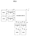
- FIG. 1 is a block diagram for explaining an example of a conventional network system (or network architecture).
- FIG. 1 illustrates a network system 1 using a two-dimensional mesh topology, such as the two-dimensional mesh torus topology.
- the network system 1 includes a crossbar switch 2, and crossbar interfaces (I/Fs) 3-1 through 3-4 that are connected to the crossbar switch 2. All data from each of the crossbar interfaces 3-1 through 3-4 is redistributed to the crossbar interfaces 3-1 through 3-4 via the crossbar switch 2.
- a node 5 is connected to each of the crossbar interfaces 3-1 through 3-4.
- the node 5 is formed by a computing node such as a processor or, an I/O (Input and Output) node.
- a computing node such as a processor or, an I/O (Input and Output) node.
- At least one of the four nodes 5 in FIG. 1 is a computing node.
- the network system 1 and the four nodes 5 form an information processing apparatus.
- a parallel computer is formed when two or more nodes 5 are formed computing nodes.
- the latency and the bandwidth have a tradeoff relationship not only in computers, but also in network systems. It is difficult to improve both the latency and the bandwidth.
- Another and more specific object of the present invention is to provide a network system, an information processing apparatus, and a control method for the network system, which may simultaneously improve both the latency and the bandwidth.
- a network system comprising a crossbar switch; and a plurality of crossbar interfaces having ports coupled to the crossbar switch, characterized in that there is provided a bypass route directly coupling crossbar interfaces forming a group in which a frequency of use of the ports is greater than or equal to a predetermined value amongst the plurality of crossbar interfaces.
- an information processing apparatus characterized in that there are provided a first computing node configured to perform a first computation and to transmit a packet; a first crossbar interface coupled to the first computing node and configured to transfer the packet transmitted from the first computing node; a crossbar switch configured to receive the packet from the first computing node coupled thereto and to switch a communication channel of the packet; a second crossbar interface coupled between the crossbar switch and the first crossbar interface, configured to transfer the packet from the crossbar switch or the first crossbar interface; and a second computing node configured to receive the packet from the second crossbar interface coupled thereto and to perform a second computation.
- an information processing apparatus comprising a crossbar switch; a plurality of nodes; a plurality of crossbar interfaces, having a plurality of ports, and coupled between the crossbar switch and the plurality of nodes; and a bypass route directly coupling crossbar interfaces forming a group in which a frequency of use of the ports is greater than or equal to a predetermined value amongst the plurality of crossbar interfaces, wherein the plurality of nodes include at least one computing node and at least one input and output node.
- a control method for a network system comprising transmitting a packet from a first computing node configured to perform a first computation; transferring a packet transmitted from the first computing node by a first crossbar interface that is coupled to the first computing node; receiving, by a crossbar switch, the packet from the first computing node that is coupled to the crossbar switch, and switching a communication channel of the packet; transferring the packet from the crossbar switch or the first crossbar interface by a second crossbar interface that is coupled to the crossbar switch and the first crossbar interface; and receiving the packet transferred by the second crossbar interface by a second computing node configured to perform a second computation.
- a control method for a network system comprising transferring a packet received by a first crossbar interface to a crossbar switch; switching, by the crossbar switch, a communication channel for the packet received from the first crossbar switch based on a communication channel selecting algorithm and transferring the packet to the communication channel determined thereby; and receiving through a bypass route the packet from the crossbar switch or the packet from the first crossbar interface by a second crossbar interface that is coupled to the crossbar switch and the first crossbar interface.
- both the latency and the bandwidth are improved by focusing attention on a bias of communication channels, that is, a bias in a frequency of use of ports (or data communication frequency).
- a bias of communication channels that is, a bias in a frequency of use of ports (or data communication frequency).
- Many parallel computers employ a communication channel selecting algorithm that avoids deadlock, such as the DOR (Dimension Order Routing) that logically avoids the deadlock.
- a communication channel selecting algorithm that avoids deadlock, such as the DOR (Dimension Order Routing) that logically avoids the deadlock.
- DOR Dission Order Routing
- a set of ports having a relatively large bias of the communication channels or a relatively high frequency of use (or data communication frequency) and a set of ports having a relatively small bias of the communication channel or a relatively low frequency of use (or data communication frequency) are generated.
- data passing through a distributed switched network are transferred by selecting the communication channels to first match a X-coordinate of target (or destination) node coordinates and to then match a Y-coordinate of the target (or destination) node. All of the data traverse the X-coordinate in the same order when matching the communication channels to the X-coordinate of the target node coordinates, and traverse the Y-coordinate in the same order when matching the communication channels to the Y-coordinate of the target node coordinates, so that the deadlock is avoided.
- a distributed switched network such as crossbar switch
- the coordinates in the two-dimensional mesh is denoted by (x, y), and that the data is transferred from coordinates (0, 0) to coordinates (n, n).
- there are n communications among the ports of the X-axis n-1 communications among the ports of the Y-axis, and 1 communication between the port of the X-axis and the port of the Y-axis.
- the number of communications among the ports of the X-axis and the number of communications among the ports of the Y-axis are large compared to the number of other communications, namely, the communication between the port of the X-axis and the port of the Y-axis.
- both the latency and the bandwidth are improved by focusing attention on the bias of the communication channels, that is, the bias in the frequency of use of the ports (or data communication frequency).
- the bias of the communication channels that is, the bias in the frequency of use of the ports (or data communication frequency).
- FIG. 2 is a block diagram for explaining an example of a network system (or network architecture) in an embodiment.
- FIG. 2 illustrates a network system 11 using a topology selected from a group including a two-dimensional mesh torus topology, a two-dimensional line torus topology, a two-dimensional mesh ring topology, and a two-dimensional line ring topology.
- the network system 11 includes a crossbar switch 12, crossbar interfaces (I/Fs) (or switch interfaces (I/Fs)) 13-1 through 13-4 connected to the crossbar switch 12, and bypass routes 14-1 and 14-2.
- I/Fs crossbar interfaces
- I/Fs switch interfaces
- Each of the crossbar interfaces 13-1 through 13-4 forming the ports are connected between the crossbar switch 12 and a corresponding one of nodes 50-1 through 50-4.
- Each of the nodes 50-1 through 50-4 is formed by a computing node or an I/O (input and output) node.
- the computing node is formed by a CPU, a processor or the like that executes various computations (or operations), for example.
- FIG. 2 at least one of the nodes 50-1 through 50-4 is formed by the computing node.
- the network system 11 and the four nodes 50-1 through 50-4 form an information processing apparatus, and a parallel computer is formed if two or more nodes among the nodes 50-1 through 50-4 are formed by computing nodes.
- the information processing apparatus includes the crossbar switch 12, the crossbar interfaces 13-1 through 13-4, the bypass routes 14-1 and 14-2, and the nodes 50-1 through 50-4.
- the data from each of the crossbar interfaces 13-1 through 13-4 is redistributed to the crossbar interfaces 13-1 through 13-4 via the crossbar switch 12 which switches the routes of the data or, is transferred to a corresponding crossbar interface via the bypass route 14-1 or 14-2.
- FIG. 3 is a diagram for explaining an example of the crossbar switch 12.
- the crossbar switch 12 includes n switches (SWs) 121 arranged in the X-axis direction, and n switches 121 arranged in the Y-axis direction, where n is a natural number greater than or equal to two.
- n communications occur among the ports of the X-axis
- n-1 communications occur among the ports of the Y-axis
- 1 communication occurs between the port of the X-axis and the port of the Y-axis.
- the number of communications among the ports of the X-axis and the number of communications among the ports of the Y-axis are large compared to the number of other communications, namely, the communication between the port of the X-axis and the port of the Y-axis.
- the crossbar interfaces 13-1 and 13-2 forming a set of ports of the X-axis having a bias of the communication channels or a frequency of use (or data communication frequency) that is higher than a predetermined value are connected by the bypass route 14-1.
- crossbar interfaces 13-3 and 13-4 forming a set of ports of the Y-axis having a bias of the communication channel or a frequency of use (or data communication frequency) that is higher than a predetermined value are connected by the bypass route 14-2.
- the crossbar interfaces that are connected by the bypass route are of course not limited to those of the example illustrated in FIG. 2 .
- the crossbar switch 12 having n ports of the X-axis and n ports of the Y-axis is of course not limited to the structure using n 2 switches 121 as illustrated in FIG. 3 .
- the crossbar interfaces 13-1 and 13-4 may be connected by a bypass route, and the crossbar interfaces 13-2 and 13-3 may be connected by a bypass route.
- the data transfer between the crossbar interfaces 13-1 and 13-2 is made directly via the bypass route 14-1 without passing through the crossbar switch 12.
- the data passing through the bypass route 14-1 is transferred directly between the ports of the crossbar interfaces 13-1 and 13-2, without passing through the crossbar switch 12.
- the data transfer may be made with a low latency compared to the case where the data transfer is made through the crossbar switch 12.
- the latency is substantially reduced because a majority of the data transfer through the crossbar interfaces 13-1 and 13-2 is made through the bypass route 14-1.
- the provision of the bypass route enables the data passing through the bypass route and other data passing through the crossbar switch 12 to be transferred simultaneously, that is, in parallel, to substantially increase the bandwidth.
- the format of the packet is not limited to a particular format.
- the packet may include routing information, such as destination information related to a packet destination and source information related to a packet source.
- the routing information is included in the header of the packet, and the data is included in the data part of the packet.
- FIG. 2 is merely for explaining the connections within the network system 11, and the physical positions of the crossbar interfaces 13-1 through 13-4 with respect to the crossbar switch 12 are not limited to the positions illustrated in FIG. 2 . Similarly, the position of each crossbar interface with respect to the crossbar switch illustrated in FIGS. 5 through 8 which will be described later is not the physical position.
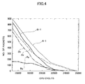
- FIG. 4 is a diagram illustrating simulation results of a performance evaluation of a simultaneous communication.
- the ordinate indicates the number of packets not reaching the destination
- the abscissa indicates the elapsed time by the number of CPU cycles.
- the packet is transferred by selecting the communication channels to first match the X-coordinate of the destination node coordinates and to then match the Y-coordinate of the destination node.
- Ax indicates the simulation result of the performance evaluation of the process of matching the communication channel that passes through the crossbar switch 12 to the X-coordinate of the destination node coordinates
- Ay indicates the simulation result of the performance evaluation of the process of matching the communication channel that passes through the crossbar switch 12 to the Y-coordinate of the destination node coordinates
- A-1 indicates the simulation result of the performance evaluation of the packet transfer from the crossbar interface 13-1 to the crossbar interface 13-2 through the crossbar switch 12.
- Bx indicates the simulation result of the performance evaluation of the process of matching the communication channel that does not pass through the crossbar switch 12 and passes directly through the bypass route 14-1 to the X-coordinate of the destination node coordinates
- B-1 indicates the simulation result of the performance evaluation of the packet transfer from the crossbar interface 13-1 to the crossbar interface 13-2 directly through the bypass route 14-1 without passing through the crossbar switch 12.
- FIG. 5 is a block diagram for explaining another example of the network system in the embodiment.
- FIG. 5 illustrates a network system 11 using a topology selected from a group including the two-dimensional mesh torus topology, the two-dimensional line torus topology, the two-dimensional mesh ring topology, and the two-dimensional line ring topology.
- those parts that are the same as those corresponding parts in FIG. 2 are designated by the same reference numerals, and a description thereof will be omitted.
- FIG. 5 employs a communication channel selecting algorithm in which the number of communications among the ports of the same axis is large compared to the number of other communications among the ports of mutually different axes.
- a crossbar interface 13-1 having ports of the +X-axis and a crossbar interface 13-2 having ports of the -X-axis are connected by a bypass route 14-1.
- a crossbar interface 13-3 having ports of the +Y-axis and a crossbar interface 13-4 having ports of the -Y-axis are connected by a bypass route 14-2.
- the ports of the +X-axis and the -X-axis of the crossbar interfaces 13-1 and 13-2 refer to the ports that are connected to the corresponding ports of the X-axis of the crossbar switch 12.
- the ports of the +Y-axis and the -Y-axis of the crossbar interfaces 13-3 and 13-4 refer to the ports that are connected to the corresponding ports of the Y-axis of the crossbar switch 12.
- the ports of the +X-axis, -X-axis, +Y-axis, and -Y-axis of the crossbar interfaces 13-1 through 13-4 are port names that are assigned to the ports for the sake of convenience.
- FIG. 6 is a block diagram for explaining another example of the network system in the embodiment.
- FIG. 6 illustrates a network system 21 using a topology selected from a group including the three-dimensional mesh torus topology, the three-dimensional line torus topology, the three-dimensional mesh ring topology, and the three-dimensional line ring topology.
- those parts that are the same as those corresponding parts in FIG. 5 are designated by the same reference numerals, and a description thereof will be omitted.
- Crossbar interfaces 13-5 and 13-6 are connected to a crossbar switch 12A illustrated in FIG. 6 , in addition to crossbar interfaces 13-1 through 13-4.
- the example illustrated in FIG. 6 employs a communication channel selecting algorithm in which the number of communications among the ports of the same axis is large compared to the number of other communications among the ports of mutually different axes.
- the crossbar interface 13-5 having ports of the +Z-axis and the crossbar interface 13-6 having ports of the -Z-axis are connected by a bypass route 14-3.
- the ports of the +Z-axis and the -Z-axis of the crossbar interfaces 13-5 and 13-6 refer to the ports that are connected to the corresponding ports of the Z-axis of the crossbar switch 12A.
- the crossbar interfaces 13-5 and 13-6 forming the ports are connected between the crossbar switch 12A and corresponding nodes 50-5 and 50-6.
- the nodes 50-5 and 50-6 may be computing nodes or I/O nodes, and in this example, at least one of the nodes 50-5 and 50-6 is a computing node.
- the network system 21 and the six nodes 50-1 through 50-6 form an information processing apparatus, and a parallel computer is formed if two or more nodes among the nodes 50-1 through 50-6 are formed by computing nodes.
- the information processing apparatus includes the crossbar switch 12A, the crossbar interfaces 13-1 through 13-6, the bypass routes 14-1 through 14-3, and the nodes 50-1 through 50-6.
- FIG. 7 is a block diagram for explaining another example of the network system in the embodiment.
- FIG. 7 illustrates a network system 31 using a topology selected from a group including the two-dimensional mesh torus topology, the two-dimensional line torus topology, the two-dimensional mesh ring topology, and the two-dimensional line ring topology.
- those parts that are the same as those corresponding parts in FIG. 5 are designated by the same reference numerals, and a description thereof will be omitted.
- FIG. 7 employs a communication channel selecting algorithm in which the number of communications among the ports of mutually different axes is large compared to the number of other communications among the ports of the same axis.
- a crossbar interface 13-1 having ports of the +X-axis and a crossbar interface 13-3 having ports of the +Y-axis are connected by a bypass route 14-4.
- a crossbar interface 13-2 having ports of the -X-axis and a crossbar interface 13-4 having ports of the -Y-axis are connected by a bypass route 14-5.
- FIG. 8 is a block diagram for explaining another example of the network system in the embodiment.
- FIG. 8 illustrates a network system 41 using a tree-type topology.
- a parent crossbar interface 13A-1 and child crossbar interfaces 13B-1 and 13B-2 are connected to a crossbar switch 12B.
- a tree structure is formed by the parent crossbar interface 13A-1 that branches to the child crossbar interfaces 13B-1 and 13B-2 through the crossbar switch 12B.
- This example employs a communication channel selecting algorithm in which the number of communications from the ports of the child crossbar interfaces 13B-1 and 13B-2 to the ports of the parent crossbar interface 13A-1 is large compared to the number of communications among the ports of the child crossbar interfaces 13B-1 and 13B-2.
- the ports of the child crossbar interface 13B-1 are connected to the ports of the parent crossbar interface 13A-1 by a bypass route 14B-1.
- the ports of the child crossbar interface 13B-2 are connected to the ports of the parent crossbar interface 13A-1 by a bypass route 14B-2.
- the bypass routes 14B-1 and 14B-2 are provided from the ports of the child crossbar interfaces 13B-1 and 13B-2 to the parent crossbar interface 13A-1, however, it is of course possible to further provide bypass routers from the ports of the crossbar interface 13A-1 to the ports of the child crossbar interfaces 13B-1 and 13B-2.
- the crossbar interfaces 13A-1, 13B-1 and 13B-2 forming the ports are connected between the crossbar switch 12B and corresponding nodes 50A-1, 50B-1 and 50B-2.
- the nodes 50A-1, 50B-1 and 50B-2 may be computing nodes or I/O nodes, and in this example, at least one of the nodes 50A-1, 50B-1 and 50B-2 is a computing node.
- the network system 41 and the three nodes 50A-1, 50B-1 and 50B-2 form an information processing apparatus, and a parallel computer is formed if two or more nodes among the nodes 50A-1, 50B-1 and 50B-2 are formed by computing nodes.
- the information processing apparatus includes the crossbar switch 12B, the crossbar interfaces 13A-1, 13B-1 and 13B-2, the bypass routes 14B-1 and 14B-2, and the nodes 50A-1, 50B-1 and 50B-2.
- a grandchild crossbar interface 13C-1 may be connected to the node 50B-1 as illustrated in FIG. 8 , and the grandchild crossbar interface 13C-1 may be connected to a great-grandchild crossbar interface (not illustrated) through a crossbar switch 12C.
- the grandchild crossbar interface 13C-1 and the great-grandchild crossbar interface may have structures similar to those of the crossbar interfaces 13A-1, 13B-1 and 13B-2.
- the crossbar switch 12C may have a structure similar to that of the crossbar switch 12B.
- a single bypass route is connected with respect to one crossbar interface.
- two or more bypass routes may be connected with respect to one crossbar interface, depending on the communication channel selecting algorithm that is employed, in order to connect two or more crossbar interfaces.
- the crossbar interface 13-1 having the ports of the +X-axis may be connected to the crossbar interface 13-5 having the ports of the +Z-axis may be connected by a bypass route.
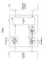
- FIG. 9 is a block diagram for explaining an example of the crossbar interface. It is assumed for the sake of convenience that the number of bypass routes 14 connected to a crossbar interface 13 in FIG. 9 is one.
- the crossbar interface 13 includes a crossbar receiving part 131, an external interface 132, a header interpreting part 133, and a crossbar transmitting part 134 that are connected as illustrated in FIG. 9 .
- the crossbar receiving part 131 receives packets from the crossbar switch 12 and packets from the bypass route 14.
- An exclusive control is carried out in advance with respect to the crossbar interface 13 in order to select the communication channel through which the packets are to be transferred depending on the communication protocol that is used, to one of the communication channel passing through the crossbar switch 12 and the communication channel passing through the bypass route 14. For this reason, the crossbar receiving part 131 supplies to the external interface 132 the packets received from the crossbar switch 12 or the packets received from the bypass route 14 according to the exclusive control.
- the external interface 132 is connected to a node 50.
- the node 50 is formed by a computing node or an I/O node.
- the node 50 outputs the packets received from the crossbar receiving part 131 to the node 50, and supplies packets received from the node 50 to the header interpreting part 133.
- the node 50 may be formed by a CPU that is mounted on a system board (not illustrated) forming a parallel computer together with a memory (not illustrated), for example.
- the node 50 may be formed by an I/O interface that is mounted on an I/O board which is separate from the system board.
- the header interpreting part 133 recognizes the target (or destination) node coordinates, that is, destination information of the packet, based on routing information included in the header of the packet received from the external interface 132, and determines the X-coordinate and the Y-coordinate of the port to which the packet is to be transferred.
- the routing information included in the header may include source information (for example, a source address) indicating the source that issued the packet, in addition to the destination information (for example, a destination address) indicating the destination to which the packet is to be transferred.
- the crossbar transmitting part 134 When the crossbar transmitting part 134 issues a request (or transmission request) and receives from the crossbar switch 12 a grant that grants a packet transmission, the crossbar transmitting part 134 outputs to the crossbar switch 12 the packet that is received from the external interface 132 via the head interpreting part 133. On the other hand, if the crossbar transmitting part 134 issues a request but a grant that grants a packet transmission is not received from the crossbar switch 12, the crossbar transmitting part 134 outputs to the bypass route 14 the packet that is received from the external interface 132 via the head interpreting part 133, and not to the crossbar switch 12.
- the crossbar transmitting part 134 may have a structure in which a plurality of buffers (not illustrated) respectively formed by a FIFO (First-In-First-Out) or the like are connected in parallel. In this case, the crossbar transmitting part 134 may hold the packet within the buffers until a grant is received from the crossbar switch 12 in response to the request issued from the crossbar transmitting part 134.
- the crossbar interface 13 has a virtual channel using such buffers, the data passing through the bypass route 14 and other data passing through the crossbar switch 12 may be transmitted simultaneously, that is, in parallel, in order to substantially increase the bandwidth.
- the parallel computer generally includes ports for the network and ports for the CPU, and may sometimes include ports for the I/O node. If it is assumed for the sake of convenience that the port names of the CPU are CPU0 and CPU1, the port names of the I/O node are IO0 and IO1, and the DOR (Dimension Order Routing) is employed, the ports CPU0 and CPU1 of the CPU have a high possibility of communicating with the ports of the +X-axis and -X-axis. For this reason, bypass routes may be provided by regarding the ports CPU0 and the ports of the +X-axis as a set (or group) and the ports CPU1 and the ports of the -X-axis as a set (or group), as illustrated in FIG. 5 or FIG. 6 . In this case, it is effective to additionally employ an algorithm that inputs to the ports CPU0 of the CPU the data output to the ports of the +X-axis on the CPU side.
- bypass routes may be provided by regarding the ports IO0 and the ports of the +Z-axis as a set (or group) and the ports IO1and the ports of the -Z-axis as a set (or group).
- network system of the embodiments described above are not only applicable to the communications of the parallel computer, and may be similarly applied to the communications of computers or information processing apparatuses in general.
- FIG. 10 is a flow chart for explaining an operation of the crossbar switch, that is, an arbitration process. For the sake of convenience, a description will be given of the operation of the crossbar switch 12 illustrated in FIG. 5 .
- a step S21 confirms a request from the ports of the +X-axis, the -X-axis, the +Y-axis and the -Y-axis
- a step S22 decides whether a packet is received from the port of one of the +X-axis, the -X-axis, the +Y-axis and the -Y-axis.
- the request indicates the output port from which he crossbar switch 12 is to output the packet received from the input port.
- a step S23 does not issue a grant granting a packet transmission to one of the +X-axis, the -X-axis, the +Y-axis and the -Y-axis, and the process advances to a step S34.
- the step S34 decides whether or not the received packet has ended, and the process returns to the step S21 if the decision result in the step S34 is YES.
- a step S24 decides whether a request is received from the port of the +X-axis.
- the process advances to a step S25 if the decision result in the step S24 is YES, and advances to a step S26 if the decision result in the step S24 is NO.
- the step S25 issues a grant granting a packet transmission to the +X-axis, and the process advances to a step S33 which will be described later.
- the step S26 decides whether a request is received from the port of the -X-axis.
- the process advances to a step S27 if the decision result in the step S26 is YES, and advances to a step S28 if the decision result in the step S26 is NO.
- the step S27 issues a grant granting a packet transmission to the -X-axis, and the process advances to the step S33.
- the step S28 decides whether a request is received from the port of the +Y-axis.
- the process advances to a step S29 if the decision result in the step S28 is YES, and advances to a step S30 if the decision result in the step S28 is NO.
- the step S29 issues a grant granting a packet transmission to the +Y-axis, and the process advances to the step S33 which will be described later.
- the step S30 decides whether a request is received from the port of the -Y-axis.
- the process advances to a step S31 if the decision result in the step S30 is YES, and advances to the step S32 if the decision result in the step S30 is NO.
- the step S31 issues a grant granting a packet transmission to the -Y-axis, and the process advances to the step S33 which will be described later.
- the step S32 does not issue a grant granting a packet transmission to one of the +X-axis, the -X-axis, the +Y-axis and the -Y-axis, and the process returns to the step 21.
- the step S33 decides whether the processing of the request has ended. The process returns to the step S21 if the decision result in the step S33 is YES.
- the crossbar switch 12 if the crossbar switch 12 receives the request in a state where no packet is received, the crossbar switch 12 issues a grant granting a packet transmission to the source of the request.
- the arbitration process described above may be executed in an output port part within the crossbar switch 12.
Abstract
Description
- The present invention relates to network systems, information processing apparatuses, and control methods for network systems.
- Performances of information processing apparatuses, such as computers, continue to improve every year. However, due to limits in reducing the size of semiconductor circuits and the saturation of a curve with which the operation clock frequency of the semiconductor circuits have increased, there is a limit to improving the performance of processors, such as CPUs (Central Processing Units). For this reason, a further improvement in the performance recently relies upon parallel computing of a parallel computer using a plurality of processors.
- The performance of the parallel computer not only depends on the computation speed of each processor itself, but also depends on the communication speed or the time required for the processors to communicate with each other. Because there is a limit to improving the performance of the processor itself according to the existing technology, it is necessary to improve the communication speed between the processors in order to further improve the performance of the parallel computer. The communication speed in the parallel computer may be roughly categorized into two elements, namely, a latency corresponding to a data transfer time, and a bandwidth corresponding to a bandwidth of the data transfer.
- The latency is the time it takes for the data communication to start and end, and the communication speed improves as the latency becomes shorter. However, when the structure of the parallel computer is made complex in order to improve the performance of the parallel computer, the logic becomes complex and the number of transistors that are used considerably increases, to thereby generate signal delays and deteriorate the latency. In addition, the effects of the latency accumulate as the scale of the parallel computer becomes larger, and makes it more difficult to further improve the performance of the parallel computer system as a whole.
- On the other hand, the bandwidth is the criterion representing the amount of data that can be transferred in one transfer. Naturally, it is desirable to transfer a large amount of data in one transfer. However, when the amount of data to be transferred in one transfer is simply increased, the number of bits to be transferred in one transfer increases. As a result, the number of transistors used for transferring and holding the data increases, to thereby increase the area of a semiconductor chip occupied by a LSI (Large Scale Integrated) circuit that forms the parallel computer. Consequently, it takes time to synchronize the data transfer when the number of bits to be transferred in one transfer increases, to thereby deteriorate the latency.
-
FIG. 1 is a block diagram for explaining an example of a conventional network system (or network architecture).FIG. 1 illustrates anetwork system 1 using a two-dimensional mesh topology, such as the two-dimensional mesh torus topology. As illustrated inFIG. 1 , thenetwork system 1 includes acrossbar switch 2, and crossbar interfaces (I/Fs) 3-1 through 3-4 that are connected to thecrossbar switch 2. All data from each of the crossbar interfaces 3-1 through 3-4 is redistributed to the crossbar interfaces 3-1 through 3-4 via thecrossbar switch 2. - A
node 5 is connected to each of the crossbar interfaces 3-1 through 3-4. Thenode 5 is formed by a computing node such as a processor or, an I/O (Input and Output) node. At least one of the fournodes 5 inFIG. 1 is a computing node. Thenetwork system 1 and the fournodes 5 form an information processing apparatus. A parallel computer is formed when two ormore nodes 5 are formed computing nodes. - As may be seen from
FIG. 1 , the latency and the bandwidth have a tradeoff relationship not only in computers, but also in network systems. It is difficult to improve both the latency and the bandwidth. - Therefore, the conventional computes and network systems suffered problems in that it is possible to improve both the latency and the bandwidth simultaneously.
- The applicant is aware of Japanese Laid-Open Patent Publications No.
11-212866 2002-328838 10-215266 - Accordingly, it is a general object of the present invention to provide a novel and useful network system, information processing apparatus, and control method for network system, in which the problems described above are suppressed.
- Another and more specific object of the present invention is to provide a network system, an information processing apparatus, and a control method for the network system, which may simultaneously improve both the latency and the bandwidth.
- According to one aspect of the present invention, there is provided a network system comprising a crossbar switch; and a plurality of crossbar interfaces having ports coupled to the crossbar switch, characterized in that there is provided a bypass route directly coupling crossbar interfaces forming a group in which a frequency of use of the ports is greater than or equal to a predetermined value amongst the plurality of crossbar interfaces.
- According to one aspect of the present invention, there is provided an information processing apparatus characterized in that there are provided a first computing node configured to perform a first computation and to transmit a packet; a first crossbar interface coupled to the first computing node and configured to transfer the packet transmitted from the first computing node; a crossbar switch configured to receive the packet from the first computing node coupled thereto and to switch a communication channel of the packet; a second crossbar interface coupled between the crossbar switch and the first crossbar interface, configured to transfer the packet from the crossbar switch or the first crossbar interface; and a second computing node configured to receive the packet from the second crossbar interface coupled thereto and to perform a second computation.
- According to one aspect of the present invention, there is provided an information processing apparatus comprising a crossbar switch; a plurality of nodes; a plurality of crossbar interfaces, having a plurality of ports, and coupled between the crossbar switch and the plurality of nodes; and a bypass route directly coupling crossbar interfaces forming a group in which a frequency of use of the ports is greater than or equal to a predetermined value amongst the plurality of crossbar interfaces, wherein the plurality of nodes include at least one computing node and at least one input and output node.
- According to one aspect of the present invention, there is provided a control method for a network system, comprising transmitting a packet from a first computing node configured to perform a first computation; transferring a packet transmitted from the first computing node by a first crossbar interface that is coupled to the first computing node; receiving, by a crossbar switch, the packet from the first computing node that is coupled to the crossbar switch, and switching a communication channel of the packet; transferring the packet from the crossbar switch or the first crossbar interface by a second crossbar interface that is coupled to the crossbar switch and the first crossbar interface; and receiving the packet transferred by the second crossbar interface by a second computing node configured to perform a second computation.
- According to one aspect of the present invention, there is provided a control method for a network system, comprising transferring a packet received by a first crossbar interface to a crossbar switch; switching, by the crossbar switch, a communication channel for the packet received from the first crossbar switch based on a communication channel selecting algorithm and transferring the packet to the communication channel determined thereby; and receiving through a bypass route the packet from the crossbar switch or the packet from the first crossbar interface by a second crossbar interface that is coupled to the crossbar switch and the first crossbar interface.
- Other objects and further features of the present invention will be apparent from the following detailed description when read in conjunction with the accompanying drawings.
-
-
FIG. 1 is a block diagram for explaining an example of a conventional network system; -
FIG. 2 is a block diagram for explaining an example of a network system in an embodiment; -
FIG. 3 is a diagram for explaining an example of a crossbar switch; -
FIG. 4 is a diagram illustrating simulation results of a performance evaluation of a simultaneous communication; -
FIG. 5 is a block diagram for explaining another example of the network system in the embodiment; -
FIG. 6 is a block diagram for explaining another example of the network system in the embodiment; -
FIG. 7 is a block diagram for explaining another example of the network system in the embodiment; -
FIG. 8 is a block diagram for explaining another example of the network system in the embodiment; -
FIG. 9 is a block diagram for explaining an example of a crossbar interface; and -
FIG. 10 is a flow chart for explaining an operation of the crossbar switch. - The disclosed network system, information processing apparatus, and control method for the network system, both the latency and the bandwidth are improved by focusing attention on a bias of communication channels, that is, a bias in a frequency of use of ports (or data communication frequency). By simultaneously improving both the latency and the bandwidth, it is possible to improve the performance of the information processing apparatus, such as parallel computers.
- A description will now be given of embodiments of the disclosed network system, information processing apparatus, and control method for the network system, by referring to the drawings.
- Many parallel computers employ a communication channel selecting algorithm that avoids deadlock, such as the DOR (Dimension Order Routing) that logically avoids the deadlock. When such a communication channel selecting algorithm is employed, a set of ports having a relatively large bias of the communication channels or a relatively high frequency of use (or data communication frequency) and a set of ports having a relatively small bias of the communication channel or a relatively low frequency of use (or data communication frequency) are generated.
- For example, when the DOR is employed in the two-dimensional mesh topology, data passing through a distributed switched network, such as crossbar switch, are transferred by selecting the communication channels to first match a X-coordinate of target (or destination) node coordinates and to then match a Y-coordinate of the target (or destination) node. All of the data traverse the X-coordinate in the same order when matching the communication channels to the X-coordinate of the target node coordinates, and traverse the Y-coordinate in the same order when matching the communication channels to the Y-coordinate of the target node coordinates, so that the deadlock is avoided. It is assumed for the sake of convenience that the coordinates in the two-dimensional mesh is denoted by (x, y), and that the data is transferred from coordinates (0, 0) to coordinates (n, n). In this case, there are n communications among the ports of the X-axis, n-1 communications among the ports of the Y-axis, and 1 communication between the port of the X-axis and the port of the Y-axis. Hence, the number of communications among the ports of the X-axis and the number of communications among the ports of the Y-axis are large compared to the number of other communications, namely, the communication between the port of the X-axis and the port of the Y-axis.
- According to an embodiment, both the latency and the bandwidth are improved by focusing attention on the bias of the communication channels, that is, the bias in the frequency of use of the ports (or data communication frequency). By simultaneously improving both the latency and the bandwidth, it is possible to improve the performance of the information processing apparatus, such as the parallel computers, for example.
-
FIG. 2 is a block diagram for explaining an example of a network system (or network architecture) in an embodiment.FIG. 2 illustrates anetwork system 11 using a topology selected from a group including a two-dimensional mesh torus topology, a two-dimensional line torus topology, a two-dimensional mesh ring topology, and a two-dimensional line ring topology. As illustrated inFIG. 2 , thenetwork system 11 includes acrossbar switch 12, crossbar interfaces (I/Fs) (or switch interfaces (I/Fs)) 13-1 through 13-4 connected to thecrossbar switch 12, and bypass routes 14-1 and 14-2. Each of the crossbar interfaces 13-1 through 13-4 forming the ports are connected between thecrossbar switch 12 and a corresponding one of nodes 50-1 through 50-4. Each of the nodes 50-1 through 50-4 is formed by a computing node or an I/O (input and output) node. The computing node is formed by a CPU, a processor or the like that executes various computations (or operations), for example. InFIG. 2 , at least one of the nodes 50-1 through 50-4 is formed by the computing node. Thenetwork system 11 and the four nodes 50-1 through 50-4 form an information processing apparatus, and a parallel computer is formed if two or more nodes among the nodes 50-1 through 50-4 are formed by computing nodes. In other words, the information processing apparatus includes thecrossbar switch 12, the crossbar interfaces 13-1 through 13-4, the bypass routes 14-1 and 14-2, and the nodes 50-1 through 50-4. - The data from each of the crossbar interfaces 13-1 through 13-4 is redistributed to the crossbar interfaces 13-1 through 13-4 via the
crossbar switch 12 which switches the routes of the data or, is transferred to a corresponding crossbar interface via the bypass route 14-1 or 14-2. -
FIG. 3 is a diagram for explaining an example of thecrossbar switch 12. In this example, thecrossbar switch 12 includes n switches (SWs) 121 arranged in the X-axis direction, and n switches 121 arranged in the Y-axis direction, where n is a natural number greater than or equal to two. When the coordinates in the two-dimensional mesh is denoted by (x, y) and the data is transferred from coordinates (0, 0) to coordinates (n, n) in thecrossbar switch 12 using the topology selected from the group including the two-dimensional mesh torus topology, the two-dimensional line torus topology, the two-dimensional mesh ring topology, and the two-dimensional line ring topology, and employing the DOR (Dimension Order Routing) as the communication channel selecting algorithm, n communications occur among the ports of the X-axis, n-1 communications occur among the ports of the Y-axis, and 1 communication occurs between the port of the X-axis and the port of the Y-axis. In this case, the number of communications among the ports of the X-axis and the number of communications among the ports of the Y-axis are large compared to the number of other communications, namely, the communication between the port of the X-axis and the port of the Y-axis. Hence, the crossbar interfaces 13-1 and 13-2 forming a set of ports of the X-axis having a bias of the communication channels or a frequency of use (or data communication frequency) that is higher than a predetermined value are connected by the bypass route 14-1. In addition, the crossbar interfaces 13-3 and 13-4 forming a set of ports of the Y-axis having a bias of the communication channel or a frequency of use (or data communication frequency) that is higher than a predetermined value are connected by the bypass route 14-2. However, the crossbar interfaces that are connected by the bypass route are of course not limited to those of the example illustrated inFIG. 2 . - The
crossbar switch 12 having n ports of the X-axis and n ports of the Y-axis is of course not limited to the structure using n2 switches 121 as illustrated inFIG. 3 . - For example, in a case where the communication channel selecting algorithm employed is such that the number of communications among the ports of mutually different axes is large compared to the number of communications among the ports of the same axis, the crossbar interfaces 13-1 and 13-4 may be connected by a bypass route, and the crossbar interfaces 13-2 and 13-3 may be connected by a bypass route.
- Accordingly, the data transfer between the crossbar interfaces 13-1 and 13-2, for example, which form the set of ports having the bias of the communication channels or the frequency of use (or data communication frequency) that is higher than the predetermined value, is made directly via the bypass route 14-1 without passing through the
crossbar switch 12. As a result, the data passing through the bypass route 14-1 is transferred directly between the ports of the crossbar interfaces 13-1 and 13-2, without passing through thecrossbar switch 12. For this reason, the data transfer may be made with a low latency compared to the case where the data transfer is made through thecrossbar switch 12. In addition, the latency is substantially reduced because a majority of the data transfer through the crossbar interfaces 13-1 and 13-2 is made through the bypass route 14-1. - Furthermore, in a case where the crossbar interface has virtual channels, the provision of the bypass route enables the data passing through the bypass route and other data passing through the
crossbar switch 12 to be transferred simultaneously, that is, in parallel, to substantially increase the bandwidth. For example, when transferring a packet from the crossbar interface 13-1 to the crossbar interface 13-2, it is possible to double the bandwidth by transferring the data via the bypass route 14-1 and simultaneously transferring the data via thecrossbar switch 12. The format of the packet is not limited to a particular format. However, in the case where the packet has the distributed routing format, the packet may include routing information, such as destination information related to a packet destination and source information related to a packet source. For example, in the case of the packet formed by a header and a data part, the routing information is included in the header of the packet, and the data is included in the data part of the packet. - Of course,
FIG. 2 is merely for explaining the connections within thenetwork system 11, and the physical positions of the crossbar interfaces 13-1 through 13-4 with respect to thecrossbar switch 12 are not limited to the positions illustrated inFIG. 2 . Similarly, the position of each crossbar interface with respect to the crossbar switch illustrated inFIGS. 5 through 8 which will be described later is not the physical position. -
FIG. 4 is a diagram illustrating simulation results of a performance evaluation of a simultaneous communication. InFIG. 4 , the ordinate indicates the number of packets not reaching the destination, and the abscissa indicates the elapsed time by the number of CPU cycles. For example, when transferring the packet from the crossbar interface 13-1 to the crossbar interface 13-2 inFIG. 2 , the packet is transferred by selecting the communication channels to first match the X-coordinate of the destination node coordinates and to then match the Y-coordinate of the destination node. InFIG. 4 , Ax indicates the simulation result of the performance evaluation of the process of matching the communication channel that passes through thecrossbar switch 12 to the X-coordinate of the destination node coordinates, Ay indicates the simulation result of the performance evaluation of the process of matching the communication channel that passes through thecrossbar switch 12 to the Y-coordinate of the destination node coordinates, and A-1 indicates the simulation result of the performance evaluation of the packet transfer from the crossbar interface 13-1 to the crossbar interface 13-2 through thecrossbar switch 12. Hence, the simulation result A-1 corresponds to a simulation result of the performance evaluation that will be obtained for the packet transfer from the crossbar interface 3-1 to the crossbar interface 3-2 through thecrossbar switch 2 in theconventional network system 1 illustrated inFIG. 1 . Further, inFIG. 4 , Bx indicates the simulation result of the performance evaluation of the process of matching the communication channel that does not pass through thecrossbar switch 12 and passes directly through the bypass route 14-1 to the X-coordinate of the destination node coordinates, By indicates the simulation result of the performance evaluation of the process of matching the communication channel that does not pass through thecrossbar switch 12 and passes directly through the bypass route 14-1 to the Y-coordinate of the destination node coordinates, and B-1 indicates the simulation result of the performance evaluation of the packet transfer from the crossbar interface 13-1 to the crossbar interface 13-2 directly through the bypass route 14-1 without passing through thecrossbar switch 12. It was confirmed from a comparison of the simulation results A-1 and B-1 that the performance is improved by 10% for the simulation result B-1 than the simulation result A-1. The simulation results inFIG. 4 were computed with respect to normalized packet transfer speeds (or rates). -
FIG. 5 is a block diagram for explaining another example of the network system in the embodiment.FIG. 5 illustrates anetwork system 11 using a topology selected from a group including the two-dimensional mesh torus topology, the two-dimensional line torus topology, the two-dimensional mesh ring topology, and the two-dimensional line ring topology. InFIG. 5 , those parts that are the same as those corresponding parts inFIG. 2 are designated by the same reference numerals, and a description thereof will be omitted. - The example illustrated in
FIG. 5 employs a communication channel selecting algorithm in which the number of communications among the ports of the same axis is large compared to the number of other communications among the ports of mutually different axes. Hence, a crossbar interface 13-1 having ports of the +X-axis and a crossbar interface 13-2 having ports of the -X-axis are connected by a bypass route 14-1. In addition, a crossbar interface 13-3 having ports of the +Y-axis and a crossbar interface 13-4 having ports of the -Y-axis are connected by a bypass route 14-2. The ports of the +X-axis and the -X-axis of the crossbar interfaces 13-1 and 13-2 refer to the ports that are connected to the corresponding ports of the X-axis of thecrossbar switch 12. Similarly, the ports of the +Y-axis and the -Y-axis of the crossbar interfaces 13-3 and 13-4 refer to the ports that are connected to the corresponding ports of the Y-axis of thecrossbar switch 12. The ports of the +X-axis, -X-axis, +Y-axis, and -Y-axis of the crossbar interfaces 13-1 through 13-4 are port names that are assigned to the ports for the sake of convenience. -
FIG. 6 is a block diagram for explaining another example of the network system in the embodiment.FIG. 6 illustrates anetwork system 21 using a topology selected from a group including the three-dimensional mesh torus topology, the three-dimensional line torus topology, the three-dimensional mesh ring topology, and the three-dimensional line ring topology. InFIG. 6 , those parts that are the same as those corresponding parts inFIG. 5 are designated by the same reference numerals, and a description thereof will be omitted. - Crossbar interfaces 13-5 and 13-6 are connected to a
crossbar switch 12A illustrated inFIG. 6 , in addition to crossbar interfaces 13-1 through 13-4. The example illustrated inFIG. 6 employs a communication channel selecting algorithm in which the number of communications among the ports of the same axis is large compared to the number of other communications among the ports of mutually different axes. Hence, the crossbar interface 13-5 having ports of the +Z-axis and the crossbar interface 13-6 having ports of the -Z-axis are connected by a bypass route 14-3. The ports of the +Z-axis and the -Z-axis of the crossbar interfaces 13-5 and 13-6 refer to the ports that are connected to the corresponding ports of the Z-axis of thecrossbar switch 12A. - The crossbar interfaces 13-5 and 13-6 forming the ports are connected between the
crossbar switch 12A and corresponding nodes 50-5 and 50-6. The nodes 50-5 and 50-6 may be computing nodes or I/O nodes, and in this example, at least one of the nodes 50-5 and 50-6 is a computing node. Thenetwork system 21 and the six nodes 50-1 through 50-6 form an information processing apparatus, and a parallel computer is formed if two or more nodes among the nodes 50-1 through 50-6 are formed by computing nodes. In other words, the information processing apparatus includes thecrossbar switch 12A, the crossbar interfaces 13-1 through 13-6, the bypass routes 14-1 through 14-3, and the nodes 50-1 through 50-6. -
FIG. 7 is a block diagram for explaining another example of the network system in the embodiment.FIG. 7 illustrates anetwork system 31 using a topology selected from a group including the two-dimensional mesh torus topology, the two-dimensional line torus topology, the two-dimensional mesh ring topology, and the two-dimensional line ring topology. InFIG. 7 , those parts that are the same as those corresponding parts inFIG. 5 are designated by the same reference numerals, and a description thereof will be omitted. - The example illustrated in
FIG. 7 employs a communication channel selecting algorithm in which the number of communications among the ports of mutually different axes is large compared to the number of other communications among the ports of the same axis. Hence, a crossbar interface 13-1 having ports of the +X-axis and a crossbar interface 13-3 having ports of the +Y-axis are connected by a bypass route 14-4. In addition, a crossbar interface 13-2 having ports of the -X-axis and a crossbar interface 13-4 having ports of the -Y-axis are connected by a bypass route 14-5. -
FIG. 8 is a block diagram for explaining another example of the network system in the embodiment.FIG. 8 illustrates anetwork system 41 using a tree-type topology. Aparent crossbar interface 13A-1 and child crossbar interfaces 13B-1 and 13B-2 are connected to acrossbar switch 12B. A tree structure is formed by theparent crossbar interface 13A-1 that branches to the child crossbar interfaces 13B-1 and 13B-2 through thecrossbar switch 12B. This example employs a communication channel selecting algorithm in which the number of communications from the ports of the child crossbar interfaces 13B-1 and 13B-2 to the ports of theparent crossbar interface 13A-1 is large compared to the number of communications among the ports of the child crossbar interfaces 13B-1 and 13B-2. Hence, the ports of thechild crossbar interface 13B-1 are connected to the ports of theparent crossbar interface 13A-1 by abypass route 14B-1. In addition, the ports of thechild crossbar interface 13B-2 are connected to the ports of theparent crossbar interface 13A-1 by abypass route 14B-2. In this example, thebypass routes 14B-1 and 14B-2 are provided from the ports of the child crossbar interfaces 13B-1 and 13B-2 to theparent crossbar interface 13A-1, however, it is of course possible to further provide bypass routers from the ports of thecrossbar interface 13A-1 to the ports of the child crossbar interfaces 13B-1 and 13B-2. - The crossbar interfaces 13A-1, 13B-1 and 13B-2 forming the ports are connected between the
crossbar switch 12B andcorresponding nodes 50A-1, 50B-1 and 50B-2. Thenodes 50A-1, 50B-1 and 50B-2 may be computing nodes or I/O nodes, and in this example, at least one of thenodes 50A-1, 50B-1 and 50B-2 is a computing node. Thenetwork system 41 and the threenodes 50A-1, 50B-1 and 50B-2 form an information processing apparatus, and a parallel computer is formed if two or more nodes among thenodes 50A-1, 50B-1 and 50B-2 are formed by computing nodes. In other words, the information processing apparatus includes thecrossbar switch 12B, the crossbar interfaces 13A-1, 13B-1 and 13B-2, thebypass routes 14B-1 and 14B-2, and thenodes 50A-1, 50B-1 and 50B-2. - When further providing a grandchild crossbar interface and a great-grandchild crossbar interface in the tree type topology, a
grandchild crossbar interface 13C-1 may be connected to thenode 50B-1 as illustrated inFIG. 8 , and thegrandchild crossbar interface 13C-1 may be connected to a great-grandchild crossbar interface (not illustrated) through acrossbar switch 12C. Thegrandchild crossbar interface 13C-1 and the great-grandchild crossbar interface may have structures similar to those of the crossbar interfaces 13A-1, 13B-1 and 13B-2. Moreover, thecrossbar switch 12C may have a structure similar to that of thecrossbar switch 12B. - In the
network systems network system 21 illustrated inFIG. 6 , for example, the crossbar interface 13-1 having the ports of the +X-axis may be connected to the crossbar interface 13-5 having the ports of the +Z-axis may be connected by a bypass route. -
FIG. 9 is a block diagram for explaining an example of the crossbar interface. It is assumed for the sake of convenience that the number ofbypass routes 14 connected to acrossbar interface 13 inFIG. 9 is one. Thecrossbar interface 13 includes acrossbar receiving part 131, anexternal interface 132, aheader interpreting part 133, and acrossbar transmitting part 134 that are connected as illustrated inFIG. 9 . - The
crossbar receiving part 131 receives packets from thecrossbar switch 12 and packets from thebypass route 14. An exclusive control is carried out in advance with respect to thecrossbar interface 13 in order to select the communication channel through which the packets are to be transferred depending on the communication protocol that is used, to one of the communication channel passing through thecrossbar switch 12 and the communication channel passing through thebypass route 14. For this reason, thecrossbar receiving part 131 supplies to theexternal interface 132 the packets received from thecrossbar switch 12 or the packets received from thebypass route 14 according to the exclusive control. - The
external interface 132 is connected to anode 50. Thenode 50 is formed by a computing node or an I/O node. Thenode 50 outputs the packets received from thecrossbar receiving part 131 to thenode 50, and supplies packets received from thenode 50 to theheader interpreting part 133. Thenode 50 may be formed by a CPU that is mounted on a system board (not illustrated) forming a parallel computer together with a memory (not illustrated), for example. In addition, thenode 50 may be formed by an I/O interface that is mounted on an I/O board which is separate from the system board. - The
header interpreting part 133 recognizes the target (or destination) node coordinates, that is, destination information of the packet, based on routing information included in the header of the packet received from theexternal interface 132, and determines the X-coordinate and the Y-coordinate of the port to which the packet is to be transferred. The routing information included in the header may include source information (for example, a source address) indicating the source that issued the packet, in addition to the destination information (for example, a destination address) indicating the destination to which the packet is to be transferred. - When the
crossbar transmitting part 134 issues a request (or transmission request) and receives from the crossbar switch 12 a grant that grants a packet transmission, thecrossbar transmitting part 134 outputs to thecrossbar switch 12 the packet that is received from theexternal interface 132 via thehead interpreting part 133. On the other hand, if thecrossbar transmitting part 134 issues a request but a grant that grants a packet transmission is not received from thecrossbar switch 12, thecrossbar transmitting part 134 outputs to thebypass route 14 the packet that is received from theexternal interface 132 via thehead interpreting part 133, and not to thecrossbar switch 12. - The
crossbar transmitting part 134 may have a structure in which a plurality of buffers (not illustrated) respectively formed by a FIFO (First-In-First-Out) or the like are connected in parallel. In this case, thecrossbar transmitting part 134 may hold the packet within the buffers until a grant is received from thecrossbar switch 12 in response to the request issued from thecrossbar transmitting part 134. When thecrossbar interface 13 has a virtual channel using such buffers, the data passing through thebypass route 14 and other data passing through thecrossbar switch 12 may be transmitted simultaneously, that is, in parallel, in order to substantially increase the bandwidth. - In a case where two or more bypass routes are connected to the crossbar interface, the structure illustrated in
FIG. 9 is of course provided with respect to each bypass route. - The parallel computer generally includes ports for the network and ports for the CPU, and may sometimes include ports for the I/O node. If it is assumed for the sake of convenience that the port names of the CPU are CPU0 and CPU1, the port names of the I/O node are IO0 and IO1, and the DOR (Dimension Order Routing) is employed, the ports CPU0 and CPU1 of the CPU have a high possibility of communicating with the ports of the +X-axis and -X-axis. For this reason, bypass routes may be provided by regarding the ports CPU0 and the ports of the +X-axis as a set (or group) and the ports CPU1 and the ports of the -X-axis as a set (or group), as illustrated in
FIG. 5 orFIG. 6 . In this case, it is effective to additionally employ an algorithm that inputs to the ports CPU0 of the CPU the data output to the ports of the +X-axis on the CPU side. - In addition, when the DOR (Dimension Order Routing) is employed, there is a high possibility that the I/O node will communicate with the ports of the Z-axis. Hence, bypass routes may be provided by regarding the ports IO0 and the ports of the +Z-axis as a set (or group) and the ports IO1and the ports of the -Z-axis as a set (or group).
- Of course, the network system of the embodiments described above are not only applicable to the communications of the parallel computer, and may be similarly applied to the communications of computers or information processing apparatuses in general.
-
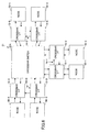
FIG. 10 is a flow chart for explaining an operation of the crossbar switch, that is, an arbitration process. For the sake of convenience, a description will be given of the operation of thecrossbar switch 12 illustrated inFIG. 5 . - In
FIG. 10 , a step S21 confirms a request from the ports of the +X-axis, the -X-axis, the +Y-axis and the -Y-axis, and a step S22 decides whether a packet is received from the port of one of the +X-axis, the -X-axis, the +Y-axis and the -Y-axis. The request indicates the output port from which hecrossbar switch 12 is to output the packet received from the input port. If the decision result in the step S22 is YES, a step S23 does not issue a grant granting a packet transmission to one of the +X-axis, the -X-axis, the +Y-axis and the -Y-axis, and the process advances to a step S34. The step S34 decides whether or not the received packet has ended, and the process returns to the step S21 if the decision result in the step S34 is YES. - If the decision result in the step S22 is NO, a step S24 decides whether a request is received from the port of the +X-axis. The process advances to a step S25 if the decision result in the step S24 is YES, and advances to a step S26 if the decision result in the step S24 is NO. The step S25 issues a grant granting a packet transmission to the +X-axis, and the process advances to a step S33 which will be described later. The step S26 decides whether a request is received from the port of the -X-axis. The process advances to a step S27 if the decision result in the step S26 is YES, and advances to a step S28 if the decision result in the step S26 is NO. The step S27 issues a grant granting a packet transmission to the -X-axis, and the process advances to the step S33. The step S28 decides whether a request is received from the port of the +Y-axis. The process advances to a step S29 if the decision result in the step S28 is YES, and advances to a step S30 if the decision result in the step S28 is NO. The step S29 issues a grant granting a packet transmission to the +Y-axis, and the process advances to the step S33 which will be described later. The step S30 decides whether a request is received from the port of the -Y-axis. The process advances to a step S31 if the decision result in the step S30 is YES, and advances to the step S32 if the decision result in the step S30 is NO. The step S31 issues a grant granting a packet transmission to the -Y-axis, and the process advances to the step S33 which will be described later. The step S32 does not issue a grant granting a packet transmission to one of the +X-axis, the -X-axis, the +Y-axis and the -Y-axis, and the process returns to the
step 21. - The step S33 decides whether the processing of the request has ended. The process returns to the step S21 if the decision result in the step S33 is YES.
- Accordingly, if the
crossbar switch 12 receives the request in a state where no packet is received, thecrossbar switch 12 issues a grant granting a packet transmission to the source of the request. The arbitration process described above may be executed in an output port part within thecrossbar switch 12. - Further, the present invention is not limited to these embodiments, but various variations and modifications may be made without departing from the scope of the present invention.
Claims (12)
- A network system comprising a crossbar switch; and a plurality of crossbar interfaces having ports coupled to the crossbar switch, characterized in that there is provided:a bypass route directly coupling crossbar interfaces forming a group in which a frequency of use of the ports is greater than or equal to a predetermined value amongst the plurality of crossbar interfaces.
- The network system as claimed in claim 1, characterized in that the crossbar interfaces directly coupled by the bypass route are determined based on a communication channel selecting algorithm.
- The network system as claimed in claim 2, characterized in that the communication channel selecting algorithm uses a DOR (Dimension Order Routing) as the communication channel selecting algorithm, and the crossbar interfaces that are directly coupled by the bypass route form ports of an axis identical to that of node coordinates of a destination of data.
- The network system as claimed in claim 2, characterized in that the crossbar interfaces that are directly coupled by the bypass route form ports of an axis different from that of node coordinates of a destination of data.
- The network system as claimed in any of claims 1 to 4, characterized in that each of the plurality of crossbar interfaces is coupled between the crossbar switch and one of a processor node and an input and output node.
- The network system as claimed in claim 5, characterized in that:each of the plurality of crossbar interfaces includes a crossbar transmitting part coupled to the crossbar switch and the bypass route, andthe crossbar transmitting part outputs to the crossbar switch a packet that is received from said one of the processor node and the input and output node when the crossbar transmitting part issues a request and receives from the crossbar switch a grant that grants a packet transmission, and outputs to the bypass route the packet that is received from said one of the processor node and the input and output node, and not to the crossbar switch, when the crossbar transmitting part issues a request but a grant that grants a packet transmission is not received from the crossbar switch.
- An information processing apparatus characterized in that there are provided:a first computing node configured to perform a first computation and to transmit a packet;a first crossbar interface coupled to the first computing node and configured to transfer the packet transmitted from the first computing node;a crossbar switch configured to receive the packet from the first computing node coupled thereto and to switch a communication channel of the packet;a second crossbar interface coupled between the crossbar switch and the first crossbar interface, configured to transfer the packet from the crossbar switch or the first crossbar interface; anda second computing node configured to receive the packet from the second crossbar interface coupled thereto and to perform a second computation.
- The information processing apparatus as claimed in claim 7, characterized in that the second crossbar interface simultaneously receives the packet from the crossbar switch and the packet from the first crossbar interface.
- The information processing apparatus as claimed in claim 7, characterized in that:the second crossbar interface includes a crossbar transmitting part coupled to the crossbar switch and the second crossbar interface, andthe crossbar transmitting part outputs to the crossbar switch a packet that is received from the second computing node when the crossbar transmitting part issues a request and receives from the crossbar switch a grant that grants a packet transmission, and outputs to the first crossbar interface the packet that is received from the second computing node, and not to the crossbar switch, when the crossbar transmitting part issues a request but a grant that grants a packet transmission is not received from the crossbar switch.
- A control method for a network system, comprising:transmitting a packet from a first computing node configured to perform a first computation;transferring a packet transmitted from the first computing node by a first crossbar interface that is coupled to the first computing node;receiving, by a crossbar switch, the packet from the first computing node that is coupled to the crossbar switch, and switching a communication channel of the packet;transferring the packet from the crossbar switch or the first crossbar interface by a second crossbar interface that is coupled to the crossbar switch and the first crossbar interface; andreceiving the packet transferred by the second crossbar interface by a second computing node configured to perform a second computation.
- The control method for the network system as claimed in claim 10, characterized in that the second crossbar interface simultaneously receives the packet from the crossbar switch and the packet from the first crossbar interface.
- The control method for the network system as claimed in claim 10, characterized in that:the second crossbar interface includes a crossbar transmitting part coupled to the crossbar switch and the second crossbar interface, andthe crossbar transmitting part outputs to the crossbar switch a packet that is received from the second computing node when the crossbar transmitting part issues a request and receives from the crossbar switch a grant that grants a packet transmission, and outputs to the first crossbar interface the packet that is received from the second computing node, and not to the crossbar switch, when the crossbar transmitting part issues a request but a grant that grants a packet transmission is not received from the crossbar switch.
Applications Claiming Priority (1)
| Application Number | Priority Date | Filing Date | Title |
|---|---|---|---|
| JP2009185893A JP5493575B2 (en) | 2009-08-10 | 2009-08-10 | Information processing apparatus and information processing apparatus control method |
Publications (3)
| Publication Number | Publication Date |
|---|---|
| EP2288084A2 true EP2288084A2 (en) | 2011-02-23 |
| EP2288084A3 EP2288084A3 (en) | 2011-08-03 |
| EP2288084B1 EP2288084B1 (en) | 2014-04-09 |
Family
ID=42797073
Family Applications (1)
| Application Number | Title | Priority Date | Filing Date |
|---|---|---|---|
| EP20100171928 Active EP2288084B1 (en) | 2009-08-10 | 2010-08-04 | Network system, information processing apparatus, and control method for network system |
Country Status (3)
| Country | Link |
|---|---|
| US (1) | US8589614B2 (en) |
| EP (1) | EP2288084B1 (en) |
| JP (1) | JP5493575B2 (en) |
Families Citing this family (8)
| Publication number | Priority date | Publication date | Assignee | Title |
|---|---|---|---|---|
| JP5493575B2 (en) * | 2009-08-10 | 2014-05-14 | 富士通株式会社 | Information processing apparatus and information processing apparatus control method |
| JP5499902B2 (en) * | 2010-05-26 | 2014-05-21 | セイコーエプソン株式会社 | Processor system |
| JP2012146201A (en) | 2011-01-13 | 2012-08-02 | Toshiba Corp | On-chip router and multi-core system using the same |
| EP2690562A4 (en) | 2011-03-22 | 2017-03-01 | Fujitsu Limited | Parallel computing system and control method of parallel computing system |
| US8983218B2 (en) | 2012-04-11 | 2015-03-17 | Texas Instruments Incorporated | Virtual boundary processing simplification for adaptive loop filtering (ALF) in video coding |
| US9081891B2 (en) * | 2012-07-31 | 2015-07-14 | Hewlett-Packard Development Company, L.P. | Reconfigurable crossbar networks |
| CN109714294B (en) * | 2017-10-25 | 2020-07-14 | 华为技术有限公司 | Physical layer chip, network security device and data forwarding method |
| US11502934B2 (en) * | 2018-08-21 | 2022-11-15 | The George Washington Univesity | EZ-pass: an energy performance-efficient power-gating router architecture for scalable on-chip interconnect architecture |
Citations (3)
| Publication number | Priority date | Publication date | Assignee | Title |
|---|---|---|---|---|
| JPH10215266A (en) | 1996-12-30 | 1998-08-11 | Compaq Computer Corp | Network switch with another cut-through buffer |
| JPH11212866A (en) | 1998-01-29 | 1999-08-06 | Nec Kofu Ltd | Multistage crossbar and computer device |
| JP2002328838A (en) | 2001-05-01 | 2002-11-15 | Nec Computertechno Ltd | Crossbar device and computer |
Family Cites Families (36)
| Publication number | Priority date | Publication date | Assignee | Title |
|---|---|---|---|---|
| JPS6373460A (en) * | 1986-09-17 | 1988-04-04 | Fujitsu Ltd | Configuration method for network of multiprocessor at broadcasting time |
| JPS63289666A (en) * | 1987-05-21 | 1988-11-28 | Toyo Commun Equip Co Ltd | Computer system |
| US5179715A (en) * | 1987-03-11 | 1993-01-12 | Toyo Communication Co., Ltd. | Multiprocessor computer system with process execution allocated by process managers in a ring configuration |
| JP2543878B2 (en) * | 1987-03-31 | 1996-10-16 | 株式会社東芝 | Parallel processing system |
| JPH02100151A (en) * | 1988-10-06 | 1990-04-12 | Nec Corp | Storage access controller |
| US5175824A (en) * | 1989-05-08 | 1992-12-29 | Trw Inc. | Crossbar switch connected modular multiprocessor system with processor timing relationship selected and synchronized to be appropriate for function being performed |
| JP2770936B2 (en) * | 1990-12-18 | 1998-07-02 | インターナショナル・ビジネス・マシーンズ・コーポレイション | Method of creating communication network and communication channel |
| US5822605A (en) * | 1994-03-24 | 1998-10-13 | Hitachi, Ltd. | Parallel processor system with a broadcast message serializing circuit provided within a network |
| JP3504033B2 (en) * | 1994-06-29 | 2004-03-08 | 株式会社日立製作所 | Data transfer method between processors and parallel computer |
| JP2607851B2 (en) * | 1994-09-17 | 1997-05-07 | 株式会社東芝 | Inter-processor routing method |
| US5721842A (en) * | 1995-08-25 | 1998-02-24 | Apex Pc Solutions, Inc. | Interconnection system for viewing and controlling remotely connected computers with on-screen video overlay for controlling of the interconnection switch |
| US6728258B1 (en) * | 1995-11-15 | 2004-04-27 | Hitachi, Ltd. | Multi-processor system and its network |
| US5898826A (en) * | 1995-11-22 | 1999-04-27 | Intel Corporation | Method and apparatus for deadlock-free routing around an unusable routing component in an N-dimensional network |
| US6285679B1 (en) * | 1997-08-22 | 2001-09-04 | Avici Systems, Inc. | Methods and apparatus for event-driven routing |
| DE19815097C2 (en) * | 1998-04-03 | 2002-03-14 | Siemens Ag | bus master |
| KR100277167B1 (en) * | 1998-06-05 | 2001-01-15 | 윤덕용 | Distributed computing system having a connection network using virtual buses and data communication method for the same |
| JP3721283B2 (en) * | 1999-06-03 | 2005-11-30 | 株式会社日立製作所 | Main memory shared multiprocessor system |
| US6751698B1 (en) * | 1999-09-29 | 2004-06-15 | Silicon Graphics, Inc. | Multiprocessor node controller circuit and method |
| US6751699B1 (en) * | 2000-07-07 | 2004-06-15 | Systran Corporation | Fibre channel mini-hub powered by and supported within a host computer and directly controlled over a bus of the host computer |
| US6973078B2 (en) * | 2001-04-20 | 2005-12-06 | Sun Microsystems, Inc. | Method and apparatus for implementing low latency crossbar switches with integrated storage signals |
| US7088678B1 (en) * | 2001-08-27 | 2006-08-08 | 3Com Corporation | System and method for traffic shaping based on generalized congestion and flow control |
| US20040022094A1 (en) * | 2002-02-25 | 2004-02-05 | Sivakumar Radhakrishnan | Cache usage for concurrent multiple streams |
| JP4338068B2 (en) * | 2002-03-20 | 2009-09-30 | 株式会社日立製作所 | Storage system |
| US8001266B1 (en) * | 2003-03-31 | 2011-08-16 | Stretch, Inc. | Configuring a multi-processor system |
| US20050044320A1 (en) * | 2003-08-19 | 2005-02-24 | Sun Microsystems, Inc. | Cache bank interface unit |
| US20050100035A1 (en) * | 2003-11-11 | 2005-05-12 | Avici Systems, Inc. | Adaptive source routing and packet processing |
| US7852836B2 (en) * | 2003-11-19 | 2010-12-14 | Cray Inc. | Reduced arbitration routing system and method |
| US7873693B1 (en) * | 2004-02-13 | 2011-01-18 | Habanero Holdings, Inc. | Multi-chassis fabric-backplane enterprise servers |
| US7486619B2 (en) * | 2004-03-04 | 2009-02-03 | International Business Machines Corporation | Multidimensional switch network |
| TWI274255B (en) * | 2004-11-08 | 2007-02-21 | Asustek Comp Inc | Motherboard |
| US7502378B2 (en) * | 2006-11-29 | 2009-03-10 | Nec Laboratories America, Inc. | Flexible wrapper architecture for tiled networks on a chip |
| US8151088B1 (en) * | 2008-07-08 | 2012-04-03 | Tilera Corporation | Configuring routing in mesh networks |
| JP4868255B2 (en) * | 2008-09-24 | 2012-02-01 | 日本電気株式会社 | Processor, processor control method, and information processing apparatus |
| JP2010218364A (en) * | 2009-03-18 | 2010-09-30 | Fujitsu Ltd | Information processing system, and communication control apparatus and method |
| US8306042B1 (en) * | 2009-06-19 | 2012-11-06 | Google Inc. | Class-based deterministic packet routing |
| JP5493575B2 (en) * | 2009-08-10 | 2014-05-14 | 富士通株式会社 | Information processing apparatus and information processing apparatus control method |
-
2009
- 2009-08-10 JP JP2009185893A patent/JP5493575B2/en active Active
-
2010
- 2010-08-04 EP EP20100171928 patent/EP2288084B1/en active Active
- 2010-08-06 US US12/805,588 patent/US8589614B2/en active Active
Patent Citations (3)
| Publication number | Priority date | Publication date | Assignee | Title |
|---|---|---|---|---|
| JPH10215266A (en) | 1996-12-30 | 1998-08-11 | Compaq Computer Corp | Network switch with another cut-through buffer |
| JPH11212866A (en) | 1998-01-29 | 1999-08-06 | Nec Kofu Ltd | Multistage crossbar and computer device |
| JP2002328838A (en) | 2001-05-01 | 2002-11-15 | Nec Computertechno Ltd | Crossbar device and computer |
Also Published As
| Publication number | Publication date |
|---|---|
| US8589614B2 (en) | 2013-11-19 |
| JP5493575B2 (en) | 2014-05-14 |
| EP2288084B1 (en) | 2014-04-09 |
| US20110035530A1 (en) | 2011-02-10 |
| JP2011039744A (en) | 2011-02-24 |
| EP2288084A3 (en) | 2011-08-03 |
Similar Documents
| Publication | Publication Date | Title |
|---|---|---|
| EP2288084B1 (en) | Network system, information processing apparatus, and control method for network system | |
| KR100812225B1 (en) | Crossbar switch architecture for multi-processor SoC platform | |
| US9742630B2 (en) | Configurable router for a network on chip (NoC) | |
| KR100758983B1 (en) | Gals based network on chip and data transfer method thereof | |
| US7889725B2 (en) | Computer cluster | |
| KR20210033996A (en) | Integrated address space for multiple hardware accelerators using dedicated low-latency links | |
| CN108683536B (en) | Configurable dual-mode converged communication method of asynchronous network on chip and interface thereof | |
| US10523599B2 (en) | Buffer sizing of a NoC through machine learning | |
| JPH06203000A (en) | Switching type multinode planer | |
| US6754838B2 (en) | Method for reducing tuning etch in a clock-forwarded interface | |
| US11537543B2 (en) | Technique for handling protocol conversion | |
| US9258358B2 (en) | Parallel computing system and control method of parallel computing system | |
| Gibiluka et al. | BAT-Hermes: a transition-signaling bundled-data NoC router | |
| Reese et al. | FA 18.4: a phase-tolerant 3.8 GB/s data-communication router for a multiprocessor supercomputer backplane | |
| JP2009194510A (en) | Priority arbitration system and priority arbitration method | |
| KR100617386B1 (en) | Asynchronous Switch Based on Butterfly Fat-Tree for Network On Chip Applications | |
| Alimi et al. | Network-on-Chip Topologies: Potentials, Technical Challenges, Recent Advances and Research Direction | |
| US20030070033A9 (en) | Parallel and point-to-point data bus architecture | |
| US20230370392A1 (en) | Network-on-chip architecture for handling different data sizes | |
| Samanth et al. | Design and Analysis of Four Port Router for Network-On-Chip Applications | |
| EP0651336A1 (en) | Switch network extension of bus architecture | |
| Trigui et al. | Mesh 2D Network on Chip with an open core protocol based network interface | |
| CN114968861A (en) | Two-write two-read data transmission structure and on-chip multi-channel interactive network | |
| Bhosale et al. | Asynchronous Router for Network-on-Chip on FPGA | |
| CN115695292A (en) | Broadcast transmission circuit based on network on chip |
Legal Events
| Date | Code | Title | Description |
|---|---|---|---|
| PUAI | Public reference made under article 153(3) epc to a published international application that has entered the european phase |
Free format text: ORIGINAL CODE: 0009012 |
|
| AK | Designated contracting states |
Kind code of ref document: A2 Designated state(s): AL AT BE BG CH CY CZ DE DK EE ES FI FR GB GR HR HU IE IS IT LI LT LU LV MC MK MT NL NO PL PT RO SE SI SK SM TR |
|
| AX | Request for extension of the european patent |
Extension state: BA ME RS |
|
| PUAL | Search report despatched |
Free format text: ORIGINAL CODE: 0009013 |
|
| AK | Designated contracting states |
Kind code of ref document: A3 Designated state(s): AL AT BE BG CH CY CZ DE DK EE ES FI FR GB GR HR HU IE IS IT LI LT LU LV MC MK MT NL NO PL PT RO SE SI SK SM TR |
|
| AX | Request for extension of the european patent |
Extension state: BA ME RS |
|
| RIC1 | Information provided on ipc code assigned before grant |
Ipc: G06F 12/08 20060101ALI20110628BHEP Ipc: H04L 12/56 20060101AFI20110628BHEP |
|
| 17P | Request for examination filed |
Effective date: 20120130 |
|
| REG | Reference to a national code |
Ref country code: DE Ref legal event code: R079 Ref document number: 602010014953 Country of ref document: DE Free format text: PREVIOUS MAIN CLASS: H04L0012560000 Ipc: H04L0012931000 |
|
| RIC1 | Information provided on ipc code assigned before grant |
Ipc: H04L 12/931 20130101AFI20130919BHEP |
|
| GRAP | Despatch of communication of intention to grant a patent |
Free format text: ORIGINAL CODE: EPIDOSNIGR1 |
|
| INTG | Intention to grant announced |
Effective date: 20131028 |
|
| RIN1 | Information on inventor provided before grant (corrected) |
Inventor name: TOYOSHIMA, TAKASHI Inventor name: TAKAGI, YUZO |
|
| GRAS | Grant fee paid |
Free format text: ORIGINAL CODE: EPIDOSNIGR3 |
|
| GRAA | (expected) grant |
Free format text: ORIGINAL CODE: 0009210 |
|
| AK | Designated contracting states |
Kind code of ref document: B1 Designated state(s): AL AT BE BG CH CY CZ DE DK EE ES FI FR GB GR HR HU IE IS IT LI LT LU LV MC MK MT NL NO PL PT RO SE SI SK SM TR |
|
| REG | Reference to a national code |
Ref country code: GB Ref legal event code: FG4D |
|
| REG | Reference to a national code |
Ref country code: AT Ref legal event code: REF Ref document number: 661853 Country of ref document: AT Kind code of ref document: T Effective date: 20140415 Ref country code: CH Ref legal event code: EP |
|
| REG | Reference to a national code |
Ref country code: IE Ref legal event code: FG4D |
|
| REG | Reference to a national code |
Ref country code: DE Ref legal event code: R096 Ref document number: 602010014953 Country of ref document: DE Effective date: 20140522 |
|
| REG | Reference to a national code |
Ref country code: AT Ref legal event code: MK05 Ref document number: 661853 Country of ref document: AT Kind code of ref document: T Effective date: 20140409 |
|
| REG | Reference to a national code |
Ref country code: NL Ref legal event code: VDEP Effective date: 20140409 |
|
| REG | Reference to a national code |
Ref country code: LT Ref legal event code: MG4D |
|
| PG25 | Lapsed in a contracting state [announced via postgrant information from national office to epo] |
Ref country code: IS Free format text: LAPSE BECAUSE OF FAILURE TO SUBMIT A TRANSLATION OF THE DESCRIPTION OR TO PAY THE FEE WITHIN THE PRESCRIBED TIME-LIMIT Effective date: 20140809 Ref country code: FI Free format text: LAPSE BECAUSE OF FAILURE TO SUBMIT A TRANSLATION OF THE DESCRIPTION OR TO PAY THE FEE WITHIN THE PRESCRIBED TIME-LIMIT Effective date: 20140409 Ref country code: GR Free format text: LAPSE BECAUSE OF FAILURE TO SUBMIT A TRANSLATION OF THE DESCRIPTION OR TO PAY THE FEE WITHIN THE PRESCRIBED TIME-LIMIT Effective date: 20140710 Ref country code: NO Free format text: LAPSE BECAUSE OF FAILURE TO SUBMIT A TRANSLATION OF THE DESCRIPTION OR TO PAY THE FEE WITHIN THE PRESCRIBED TIME-LIMIT Effective date: 20140709 Ref country code: LT Free format text: LAPSE BECAUSE OF FAILURE TO SUBMIT A TRANSLATION OF THE DESCRIPTION OR TO PAY THE FEE WITHIN THE PRESCRIBED TIME-LIMIT Effective date: 20140409 Ref country code: NL Free format text: LAPSE BECAUSE OF FAILURE TO SUBMIT A TRANSLATION OF THE DESCRIPTION OR TO PAY THE FEE WITHIN THE PRESCRIBED TIME-LIMIT Effective date: 20140409 Ref country code: BG Free format text: LAPSE BECAUSE OF FAILURE TO SUBMIT A TRANSLATION OF THE DESCRIPTION OR TO PAY THE FEE WITHIN THE PRESCRIBED TIME-LIMIT Effective date: 20140709 |
|
| PG25 | Lapsed in a contracting state [announced via postgrant information from national office to epo] |
Ref country code: LV Free format text: LAPSE BECAUSE OF FAILURE TO SUBMIT A TRANSLATION OF THE DESCRIPTION OR TO PAY THE FEE WITHIN THE PRESCRIBED TIME-LIMIT Effective date: 20140409 Ref country code: SE Free format text: LAPSE BECAUSE OF FAILURE TO SUBMIT A TRANSLATION OF THE DESCRIPTION OR TO PAY THE FEE WITHIN THE PRESCRIBED TIME-LIMIT Effective date: 20140409 Ref country code: PL Free format text: LAPSE BECAUSE OF FAILURE TO SUBMIT A TRANSLATION OF THE DESCRIPTION OR TO PAY THE FEE WITHIN THE PRESCRIBED TIME-LIMIT Effective date: 20140409 Ref country code: AT Free format text: LAPSE BECAUSE OF FAILURE TO SUBMIT A TRANSLATION OF THE DESCRIPTION OR TO PAY THE FEE WITHIN THE PRESCRIBED TIME-LIMIT Effective date: 20140409 Ref country code: HR Free format text: LAPSE BECAUSE OF FAILURE TO SUBMIT A TRANSLATION OF THE DESCRIPTION OR TO PAY THE FEE WITHIN THE PRESCRIBED TIME-LIMIT Effective date: 20140409 Ref country code: ES Free format text: LAPSE BECAUSE OF FAILURE TO SUBMIT A TRANSLATION OF THE DESCRIPTION OR TO PAY THE FEE WITHIN THE PRESCRIBED TIME-LIMIT Effective date: 20140409 |
|
| PG25 | Lapsed in a contracting state [announced via postgrant information from national office to epo] |
Ref country code: PT Free format text: LAPSE BECAUSE OF FAILURE TO SUBMIT A TRANSLATION OF THE DESCRIPTION OR TO PAY THE FEE WITHIN THE PRESCRIBED TIME-LIMIT Effective date: 20140811 |
|
| REG | Reference to a national code |
Ref country code: DE Ref legal event code: R097 Ref document number: 602010014953 Country of ref document: DE |
|
| PG25 | Lapsed in a contracting state [announced via postgrant information from national office to epo] |
Ref country code: EE Free format text: LAPSE BECAUSE OF FAILURE TO SUBMIT A TRANSLATION OF THE DESCRIPTION OR TO PAY THE FEE WITHIN THE PRESCRIBED TIME-LIMIT Effective date: 20140409 Ref country code: DK Free format text: LAPSE BECAUSE OF FAILURE TO SUBMIT A TRANSLATION OF THE DESCRIPTION OR TO PAY THE FEE WITHIN THE PRESCRIBED TIME-LIMIT Effective date: 20140409 Ref country code: CZ Free format text: LAPSE BECAUSE OF FAILURE TO SUBMIT A TRANSLATION OF THE DESCRIPTION OR TO PAY THE FEE WITHIN THE PRESCRIBED TIME-LIMIT Effective date: 20140409 Ref country code: BE Free format text: LAPSE BECAUSE OF FAILURE TO SUBMIT A TRANSLATION OF THE DESCRIPTION OR TO PAY THE FEE WITHIN THE PRESCRIBED TIME-LIMIT Effective date: 20140409 Ref country code: SK Free format text: LAPSE BECAUSE OF FAILURE TO SUBMIT A TRANSLATION OF THE DESCRIPTION OR TO PAY THE FEE WITHIN THE PRESCRIBED TIME-LIMIT Effective date: 20140409 Ref country code: RO Free format text: LAPSE BECAUSE OF FAILURE TO SUBMIT A TRANSLATION OF THE DESCRIPTION OR TO PAY THE FEE WITHIN THE PRESCRIBED TIME-LIMIT Effective date: 20140409 |
|
| PLBE | No opposition filed within time limit |
Free format text: ORIGINAL CODE: 0009261 |
|
| STAA | Information on the status of an ep patent application or granted ep patent |
Free format text: STATUS: NO OPPOSITION FILED WITHIN TIME LIMIT |
|
| 26N | No opposition filed |
Effective date: 20150112 |
|
| PG25 | Lapsed in a contracting state [announced via postgrant information from national office to epo] |
Ref country code: LU Free format text: LAPSE BECAUSE OF FAILURE TO SUBMIT A TRANSLATION OF THE DESCRIPTION OR TO PAY THE FEE WITHIN THE PRESCRIBED TIME-LIMIT Effective date: 20140804 Ref country code: IT Free format text: LAPSE BECAUSE OF FAILURE TO SUBMIT A TRANSLATION OF THE DESCRIPTION OR TO PAY THE FEE WITHIN THE PRESCRIBED TIME-LIMIT Effective date: 20140409 Ref country code: MC Free format text: LAPSE BECAUSE OF FAILURE TO SUBMIT A TRANSLATION OF THE DESCRIPTION OR TO PAY THE FEE WITHIN THE PRESCRIBED TIME-LIMIT Effective date: 20140409 |
|
| REG | Reference to a national code |
Ref country code: CH Ref legal event code: PL |
|
| REG | Reference to a national code |
Ref country code: DE Ref legal event code: R097 Ref document number: 602010014953 Country of ref document: DE Effective date: 20150112 |
|
| PG25 | Lapsed in a contracting state [announced via postgrant information from national office to epo] |
Ref country code: LI Free format text: LAPSE BECAUSE OF NON-PAYMENT OF DUE FEES Effective date: 20140831 Ref country code: CH Free format text: LAPSE BECAUSE OF NON-PAYMENT OF DUE FEES Effective date: 20140831 |
|
| REG | Reference to a national code |
Ref country code: IE Ref legal event code: MM4A |
|
| PG25 | Lapsed in a contracting state [announced via postgrant information from national office to epo] |
Ref country code: SI Free format text: LAPSE BECAUSE OF FAILURE TO SUBMIT A TRANSLATION OF THE DESCRIPTION OR TO PAY THE FEE WITHIN THE PRESCRIBED TIME-LIMIT Effective date: 20140409 |
|
| PG25 | Lapsed in a contracting state [announced via postgrant information from national office to epo] |
Ref country code: IE Free format text: LAPSE BECAUSE OF NON-PAYMENT OF DUE FEES Effective date: 20140804 |
|
| PG25 | Lapsed in a contracting state [announced via postgrant information from national office to epo] |
Ref country code: SM Free format text: LAPSE BECAUSE OF FAILURE TO SUBMIT A TRANSLATION OF THE DESCRIPTION OR TO PAY THE FEE WITHIN THE PRESCRIBED TIME-LIMIT Effective date: 20140409 |
|
| PG25 | Lapsed in a contracting state [announced via postgrant information from national office to epo] |
Ref country code: CY Free format text: LAPSE BECAUSE OF FAILURE TO SUBMIT A TRANSLATION OF THE DESCRIPTION OR TO PAY THE FEE WITHIN THE PRESCRIBED TIME-LIMIT Effective date: 20140409 Ref country code: MT Free format text: LAPSE BECAUSE OF FAILURE TO SUBMIT A TRANSLATION OF THE DESCRIPTION OR TO PAY THE FEE WITHIN THE PRESCRIBED TIME-LIMIT Effective date: 20140409 |
|
| REG | Reference to a national code |
Ref country code: FR Ref legal event code: PLFP Year of fee payment: 7 |
|
| PG25 | Lapsed in a contracting state [announced via postgrant information from national office to epo] |
Ref country code: TR Free format text: LAPSE BECAUSE OF FAILURE TO SUBMIT A TRANSLATION OF THE DESCRIPTION OR TO PAY THE FEE WITHIN THE PRESCRIBED TIME-LIMIT Effective date: 20140409 Ref country code: HU Free format text: LAPSE BECAUSE OF FAILURE TO SUBMIT A TRANSLATION OF THE DESCRIPTION OR TO PAY THE FEE WITHIN THE PRESCRIBED TIME-LIMIT; INVALID AB INITIO Effective date: 20100804 |
|
| REG | Reference to a national code |
Ref country code: FR Ref legal event code: PLFP Year of fee payment: 8 |
|
| PG25 | Lapsed in a contracting state [announced via postgrant information from national office to epo] |
Ref country code: MK Free format text: LAPSE BECAUSE OF FAILURE TO SUBMIT A TRANSLATION OF THE DESCRIPTION OR TO PAY THE FEE WITHIN THE PRESCRIBED TIME-LIMIT Effective date: 20140409 |
|
| REG | Reference to a national code |
Ref country code: FR Ref legal event code: PLFP Year of fee payment: 9 |
|
| PG25 | Lapsed in a contracting state [announced via postgrant information from national office to epo] |
Ref country code: AL Free format text: LAPSE BECAUSE OF FAILURE TO SUBMIT A TRANSLATION OF THE DESCRIPTION OR TO PAY THE FEE WITHIN THE PRESCRIBED TIME-LIMIT Effective date: 20140409 |
|
| REG | Reference to a national code |
Ref country code: DE Ref legal event code: R079 Ref document number: 602010014953 Country of ref document: DE Free format text: PREVIOUS MAIN CLASS: H04L0012931000 Ipc: H04L0049100000 |
|
| PGFP | Annual fee paid to national office [announced via postgrant information from national office to epo] |
Ref country code: GB Payment date: 20230629 Year of fee payment: 14 |
|
| PGFP | Annual fee paid to national office [announced via postgrant information from national office to epo] |
Ref country code: FR Payment date: 20230703 Year of fee payment: 14 Ref country code: DE Payment date: 20230627 Year of fee payment: 14 |