EP2287014B1 - Portable carrier device - Google Patents
Portable carrier device Download PDFInfo
- Publication number
- EP2287014B1 EP2287014B1 EP10192191.4A EP10192191A EP2287014B1 EP 2287014 B1 EP2287014 B1 EP 2287014B1 EP 10192191 A EP10192191 A EP 10192191A EP 2287014 B1 EP2287014 B1 EP 2287014B1
- Authority
- EP
- European Patent Office
- Prior art keywords
- carrier
- elements
- marker
- carrier elements
- configuration
- Prior art date
- Legal status (The legal status is an assumption and is not a legal conclusion. Google has not performed a legal analysis and makes no representation as to the accuracy of the status listed.)
- Expired - Lifetime
Links
Images




Classifications
-
- G—PHYSICS
- G09—EDUCATION; CRYPTOGRAPHY; DISPLAY; ADVERTISING; SEALS
- G09F—DISPLAYING; ADVERTISING; SIGNS; LABELS OR NAME-PLATES; SEALS
- G09F3/00—Labels, tag tickets, or similar identification or indication means; Seals; Postage or like stamps
- G09F3/02—Forms or constructions
- G09F3/0295—Labels or tickets for tubes, pipes and the like
-
- B—PERFORMING OPERATIONS; TRANSPORTING
- B44—DECORATIVE ARTS
- B44B—MACHINES, APPARATUS OR TOOLS FOR ARTISTIC WORK, e.g. FOR SCULPTURING, GUILLOCHING, CARVING, BRANDING, INLAYING
- B44B5/00—Machines or apparatus for embossing decorations or marks, e.g. embossing coins
- B44B5/02—Dies; Accessories
-
- B—PERFORMING OPERATIONS; TRANSPORTING
- B65—CONVEYING; PACKING; STORING; HANDLING THIN OR FILAMENTARY MATERIAL
- B65C—LABELLING OR TAGGING MACHINES, APPARATUS, OR PROCESSES
- B65C9/00—Details of labelling machines or apparatus
- B65C9/08—Label feeding
- B65C9/10—Label magazines
-
- B—PERFORMING OPERATIONS; TRANSPORTING
- B65—CONVEYING; PACKING; STORING; HANDLING THIN OR FILAMENTARY MATERIAL
- B65C—LABELLING OR TAGGING MACHINES, APPARATUS, OR PROCESSES
- B65C9/00—Details of labelling machines or apparatus
- B65C9/08—Label feeding
- B65C9/12—Removing separate labels from stacks
-
- B—PERFORMING OPERATIONS; TRANSPORTING
- B65—CONVEYING; PACKING; STORING; HANDLING THIN OR FILAMENTARY MATERIAL
- B65H—HANDLING THIN OR FILAMENTARY MATERIAL, e.g. SHEETS, WEBS, CABLES
- B65H5/00—Feeding articles separated from piles; Feeding articles to machines
-
- G—PHYSICS
- G09—EDUCATION; CRYPTOGRAPHY; DISPLAY; ADVERTISING; SEALS
- G09F—DISPLAYING; ADVERTISING; SIGNS; LABELS OR NAME-PLATES; SEALS
- G09F3/00—Labels, tag tickets, or similar identification or indication means; Seals; Postage or like stamps
- G09F3/08—Fastening or securing by means not forming part of the material of the label itself
- G09F3/18—Casings, frames or enclosures for labels
- G09F3/20—Casings, frames or enclosures for labels for adjustable, removable, or interchangeable labels
-
- G—PHYSICS
- G09—EDUCATION; CRYPTOGRAPHY; DISPLAY; ADVERTISING; SEALS
- G09F—DISPLAYING; ADVERTISING; SIGNS; LABELS OR NAME-PLATES; SEALS
- G09F3/00—Labels, tag tickets, or similar identification or indication means; Seals; Postage or like stamps
- G09F3/08—Fastening or securing by means not forming part of the material of the label itself
- G09F3/18—Casings, frames or enclosures for labels
- G09F3/20—Casings, frames or enclosures for labels for adjustable, removable, or interchangeable labels
- G09F3/205—Casings, frames or enclosures for labels for adjustable, removable, or interchangeable labels specially adapted for electric cables, pipes or the like
Definitions
- the present invention relates to a portable carrier device for carrying individual pre-formed markers.
- Elongate marker strips of plastics, metal or other materials are known for the purpose of identifying, for example electric cables.
- the markers are typically printed or embossed with an identifier indicia and attached to the cable, in order to identify the relevant cable.
- GB 2 137 586 A describes a device for holding cable sleeves comprising bendable fingers onto which the sleeves are longitudinally inserted or removed with the fingers being bent from that rest position to facilitate this insertion and removal.
- JP2003107998 describes a display for holding material in a fanned out configuration that is permanently fixed to a wall structure.
- the marker elements are presented in a fanned out configuration in the selection configuration, and in a non fanned out configuration in the compact configuration. Beneficially, the marker elements are presented in a radially spaced array in the selection configuration.
- the carrier elements preferably interlock one another in the compact configuration.
- the carrier elements are preferably rotatable relative to one another to move between the compact configuration and the selection configuration.
- the carrier elements are arranged in a stack or row when in the compact configuration. It is preferred that the system includes detent means for retaining the carrier elements interlocked in the compact configuration.
- the carrier elements are provided with complementary engaging formations comprising the detent means. It is desirable that the detent means is capable of being overcome by hand force in order to move the carrier elements from the compact position.
- the carrier elements according to the present invention include grip means for retaining the respective marker elements.
- the grip means may comprise one or more resilient clamp elements provided for a respective carrier element
- the clamp element is preferably biassed to a normally clamped position.
- the carrier elements and the marker elements are elongate and the grip means are configured to receive and retain the marker elements in a transfer direction which is transverse to the longitudinal direction.
- the carrier elements are rotatable about a common pivot spine.
- the common pivot spine is positioned proximate one end of the respective carrier elements.
- the arrangement enables that the marker elements are removed from the respective carrier elements in both the- compact and the selection configuration. This aids in automatic handling such as for example enabling the marker elements to be picked from the device when in the compact configuration, loaded in a printing or embossing device.
- the carrier elements are configured, beneficially, to receive a single marker element.
- the marker elements are substantially laid flat received on a support of the respective carrier element.
- the respective marker elements are returned to the carrier device following marking.
- the carrier device preferably comprises a plurality of movable carrier elements re-configurable between a compact configuration and a selection configuration in which the markers are accessibly presented for selection, the carrier elements being moved to the selection configuration to enable the marker elements to be selected for marking in the marking unit.
- the carrier device for individual selected flat markers 2.
- the carrier device includes a series of elongate carrier elements 3, each shaped and configured to hold a single respective marker 2.
- the carrier elements 3 are of plastics material and joined at a common pivotal spine 4 such that each respective carrier element is pivotal relative to others in the device 1.
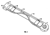
- the pivotal spine is formed by boss formations 6 (formed integrally at the ends of respective carrier elements 3), and arranged to rotatably engage with a socket formation 7 provided on the reverse sides of the carrier elements (these are shown most clearly in figures 3 and 4 ).
- a resilient plastics clip 23 is used to hold the spine together.
- the distal end of the respective carrier elements 3 are provided with detent formations 9, 10 on the reverse side with locate in the boundary formed by a recess12 on the obverse side of the carrier elements.
- the adjacent carrier elements 2 can interlock and the carrier device 1 can be held in a compact or closed interlocked configuration in which the carriers are 'in-line' in a row or stack (bottom seven carrier elements in figure 1 ) or 'fanned out' in a pivotally radially spaced 'selection' configuration, in which the markers 2 can be easily seen and selected (upper three carrier elements in figure 1 ).
- the detent formations are shaped and dimensioned with respect to the recess 12 such that the carrier elements can be held 'in line' in the compact configuration, but displaced to the fanned out selection configuration by the user by hand.
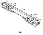
- the body of the carrier element comprises a longitudinal spine 13 and supports 14, 19, 20 against which the marker element is clamped by means of longitudinally spaced clams 15, 16.
- the clamps 15,16 included spaced resilient arms 22 which are shaped and configured to be normally biassed to a position of clamping engagement. As the marker element 2 slides into and out of the clamps 15, 16 the arms 22 resiliently flex. The majority of the upper surface of the markers 2 when clamped to a respective carrier element are visible, which makes correct marker element identification and selection easier.
- FIG. 5 An alternative embodiment of carrier device 101 is shown in figures 5 to 8 .
- the device 101 is generally similar to the device of figures 1 to 4 , however in this instance the spines 113 of the carrier elements are mounted pivotally in a housing case 151 within which the carrier elements 103 are received in the compact configuration as shown in figure 5 .
- the carrier elements 103 are configured generally as the carrier elements 3 of the previous embodiment except in relation to the free end detail.
- the free end of the carrier elements is provided with a resilient detent 154 to cooperate with a detent shoulder (not shown) on the inside of the distal end wall 155 of the housing case 151. This ensures the carrier elements 103 are generally securely retained within the housing case 151 but permits manual force to move the carrier element pivotally from the housing case 151.
- the projection 157 carrying the detent 154 enables the user to grip the carrier element for movement, and also provides a resilient connection at bridge portion 158.
- Projecting upwardly from the distal end of the carrier element 103 is a lug 109 which is arrayed to be received in a slot 110 (shown in dashed line in figure 8 ) which is provided on the underside of the immediately upwardly adjacent carrier element 103 in the stack.
- the marker elements are loaded (either manually or mechanically) into the carrier elements 2 of a carrier device 1 in an unmarked state.
- the unmarked, marker loaded, device is transported to a use location together with a portable marker unit 25as shown in figures 5A and 5B .
- the portable marker unit 25 comprises a programmable input device 26 (such as an alpha numeric key pad) and a processor 27.
- the processor 27 controls a picker device 28 and embossing device 29.
- the carrier device 1 is loaded into the unit at a docking station 30.
- the picker device 28 and embossing device 29 are arranged to be indexed upwardly or downwardly to adjacent successive carrier elements 2, and operate to slide out the marker elements 2 from the carrier elements 3 in a direction away from the spine 13.
- the picker device 28 then transfers the marker element 2 to the embossing device where the appropriate indicia is embossed onto the marker element 2. Subsequently, the marker element is returned by the picker device 28 to the respective carrier element from which it was originally selected.
- a magazine containing a number of carrier devices 1 can be loaded into a loading station for the unit.
- a single carrier device 1 is then fed to the docking station 30 for embossing of the blank marker elements 2.
- the unit can be used for relatively high embossing runs.
- a separate dispatch station may be provided for the unit. Following embossing of all required marker elements in a relevant carrier 1, the carrier may pass to the dispatch station whilst a further carrier 1 to be concurrently loaded for embossing.
- the unit may therefore, store and process carriers effectively continuously.
- the carrier device 1 could be moved in an indexed manner.
- the carrier elements 2 of the carrier device 1, when positioned in the docking station 30, could be displaced pivotally to enable easier access for embossing and/or picking.
- other configurations of carrier device to be used.
- a disc carrier with the marker elements aligned radially could be used.
- the disc carrier could be mounted for rotary indexing in the docking station and the marker elements moved radially into and out of the carrier.
- the carrier device 1 provides a convenient means of carrying and selecting the markers when in use.
- FIGS 10 and 11 disclose an exemplary embodiment which is not part of the present invention.
- a portable marker unit 225 includes a magazine 230 having upper and lower racks 237, 238.
- a bank of carrier devices 201 loaded with unmarked markers is loaded in file (one behind another) onto the lower rack 237.
- the carrier devices 201 are fed in succession to a forward picking station 301 of the rack. With the carrier device 201 in position at picking station 301 a picker device 228 operates to retrieve individual marker elements, in sequence, from the carrier device and transfer them to an embossing station 229 to be marked with the pre-programmed indicia.
- the picker device 228 includes a conveyor 341 to move toward and away from the carrier device and embossing station, a carriage 345 including an electric motor drive to move the carriage 345 and picker device 228 transversely across the unit supported on a rail 359 between the picking station 301 and the embossing station 229 by means of a conveyor 352.
- the carrier device When each marker in a carrier device 201 has been picked, embossed and returned to the respective carrier device, the carrier device is driven upwardly from the picking station 229 lower rack 238 and loaded onto the upper rack 237, for subsequent onward shipment.
Landscapes
- Engineering & Computer Science (AREA)
- Physics & Mathematics (AREA)
- General Physics & Mathematics (AREA)
- Theoretical Computer Science (AREA)
- Mechanical Engineering (AREA)
- Warehouses Or Storage Devices (AREA)
- Automatic Analysis And Handling Materials Therefor (AREA)
- Labeling Devices (AREA)
- Credit Cards Or The Like (AREA)
Description
- The present invention relates to a portable carrier device for carrying individual pre-formed markers.
- Elongate marker strips of plastics, metal or other materials are known for the purpose of identifying, for example electric cables. The markers are typically printed or embossed with an identifier indicia and attached to the cable, in order to identify the relevant cable.
- An improved marker system and carrier device for such markers have been devised.
- According to the present invention there is provided a carrier device as defined by the accompanying claims.
GB 2 137 586 AJP2003107998 - The marker elements are presented in a fanned out configuration in the selection configuration, and in a non fanned out configuration in the compact configuration. Beneficially, the marker elements are presented in a radially spaced array in the selection configuration. The carrier elements preferably interlock one another in the compact configuration. The carrier elements are preferably rotatable relative to one another to move between the compact configuration and the selection configuration.
- Desirably, the carrier elements are arranged in a stack or row when in the compact configuration.
It is preferred that the system includes detent means for retaining the carrier elements interlocked in the compact configuration. Advantageously, the carrier elements are provided with complementary engaging formations comprising the detent means. It is desirable that the detent means is capable of being overcome by hand force in order to move the carrier elements from the compact position. - The carrier elements according to the present invention include grip means for retaining the respective marker elements. The grip means may comprise one or more resilient clamp elements provided for a respective carrier element The clamp element is preferably biassed to a normally clamped position.
- The carrier elements and the marker elements are elongate and the grip means are configured to receive and retain the marker elements in a transfer direction which is transverse to the longitudinal direction. Preferably the carrier elements are rotatable about a common pivot spine. Beneficially the common pivot spine is positioned proximate one end of the respective carrier elements.
- Moreover, the arrangement enables that the marker elements are removed from the respective carrier elements in both the- compact and the selection configuration. This aids in automatic handling such as for example enabling the marker elements to be picked from the device when in the compact configuration, loaded in a printing or embossing device.
- The carrier elements are configured, beneficially, to receive a single marker element. Desirably, the marker elements are substantially laid flat received on a support of the respective carrier element.
- Beneficially, the respective marker elements are returned to the carrier device following marking.
- The carrier device preferably comprises a plurality of movable carrier elements re-configurable between a compact configuration and a selection configuration in which the markers are accessibly presented for selection, the carrier elements being moved to the selection configuration to enable the marker elements to be selected for marking in the marking unit.
- The invention will now be further described, by way of example only, and with reference to the accompanying drawings, in which:
-
Figure 1 is a perspective view of a carrier device according to the invention:-
Figure 2 is an alternative perspective view of the carrier device offigure 1 ; -
Figure 3 is a perspective view of a carrier element comprising the carrier device of the preceding figures; -
Figure 4 is an alternative perspective view of the carrier element offigure 3 ; -
Figures 5, 6 and 7 are perspective views of an alternative embodiment of a carrier device in sequential steps between compact configuration and fanned out selection configuration; -
Figure 8 is a detailed view of an end of a carrier element of the device ofFigures 5 to 6 ; -
Figures 9A and 9B are side and end views respectively of a marker system which is not part of the present invention; -
Figure 10 is a perspective view of an exemplary marker system which is not part of this invention; and -
Figure 11 is a view of a part of the system ofFigure 10 .
-
- Referring to the drawings, and initially to
figures 1 and2 , there is shown acarrier device 1 for individual selectedflat markers 2. The carrier device includes a series ofelongate carrier elements 3, each shaped and configured to hold a singlerespective marker 2. Thecarrier elements 3 are of plastics material and joined at a commonpivotal spine 4 such that each respective carrier element is pivotal relative to others in thedevice 1. The pivotal spine is formed by boss formations 6 (formed integrally at the ends of respective carrier elements 3), and arranged to rotatably engage with asocket formation 7 provided on the reverse sides of the carrier elements (these are shown most clearly infigures 3 and4 ). Aresilient plastics clip 23 is used to hold the spine together. - The distal end of the
respective carrier elements 3 are provided withdetent formations adjacent carrier elements 2 can interlock and thecarrier device 1 can be held in a compact or closed interlocked configuration in which the carriers are 'in-line' in a row or stack (bottom seven carrier elements infigure 1 ) or 'fanned out' in a pivotally radially spaced 'selection' configuration, in which themarkers 2 can be easily seen and selected (upper three carrier elements infigure 1 ). The detent formations are shaped and dimensioned with respect to therecess 12 such that the carrier elements can be held 'in line' in the compact configuration, but displaced to the fanned out selection configuration by the user by hand. - The body of the carrier element comprises a
longitudinal spine 13 and supports 14, 19, 20 against which the marker element is clamped by means of longitudinally spacedclams clamps resilient arms 22 which are shaped and configured to be normally biassed to a position of clamping engagement. As themarker element 2 slides into and out of theclamps arms 22 resiliently flex. The majority of the upper surface of themarkers 2 when clamped to a respective carrier element are visible, which makes correct marker element identification and selection easier. - An alternative embodiment of carrier device 101 is shown in
figures 5 to 8 . The device 101 is generally similar to the device offigures 1 to 4 , however in this instance thespines 113 of the carrier elements are mounted pivotally in ahousing case 151 within which thecarrier elements 103 are received in the compact configuration as shown infigure 5 . Thecarrier elements 103 are configured generally as thecarrier elements 3 of the previous embodiment except in relation to the free end detail. As shown infigure 8 , the free end of the carrier elements is provided with aresilient detent 154 to cooperate with a detent shoulder (not shown) on the inside of thedistal end wall 155 of thehousing case 151. This ensures thecarrier elements 103 are generally securely retained within thehousing case 151 but permits manual force to move the carrier element pivotally from thehousing case 151. Theprojection 157 carrying thedetent 154 enables the user to grip the carrier element for movement, and also provides a resilient connection atbridge portion 158. Projecting upwardly from the distal end of thecarrier element 103 is alug 109 which is arrayed to be received in a slot 110 (shown in dashed line infigure 8 ) which is provided on the underside of the immediately upwardlyadjacent carrier element 103 in the stack. In this way, pulling out thelowermost carrier element 103 causes the entire stack ofcarrier elements 103 to fan out (as shown progressively infigures 6 and 7 ) as thelugs 109 move inslots 110 and then cause the adjacent carrier to pivotally move (fanning out) when thelug 109 abuts the end of the slot of the respective upwardlyadjacent carrier elements 103. In the selection configuration shown infigure 7 , the carrier elements are fully fanned giving clear view of themarkers 108 in the carrier device. - Typically the marker elements are loaded (either manually or mechanically) into the
carrier elements 2 of acarrier device 1 in an unmarked state. The unmarked, marker loaded, device is transported to a use location together with a portable marker unit 25as shown infigures 5A and 5B . Theportable marker unit 25 comprises a programmable input device 26 (such as an alpha numeric key pad) and aprocessor 27. Theprocessor 27 controls apicker device 28 andembossing device 29. Thecarrier device 1 is loaded into the unit at adocking station 30. Thepicker device 28 andembossing device 29 are arranged to be indexed upwardly or downwardly to adjacentsuccessive carrier elements 2, and operate to slide out themarker elements 2 from thecarrier elements 3 in a direction away from thespine 13. thepicker device 28 then transfers themarker element 2 to the embossing device where the appropriate indicia is embossed onto themarker element 2. Subsequently, the marker element is returned by thepicker device 28 to the respective carrier element from which it was originally selected. - In a modified embodiment a magazine containing a number of carrier devices 1 (for example ten) can be loaded into a loading station for the unit. A
single carrier device 1 is then fed to thedocking station 30 for embossing of theblank marker elements 2. In this way the unit can be used for relatively high embossing runs. In addition a separate dispatch station may be provided for the unit. Following embossing of all required marker elements in arelevant carrier 1, the carrier may pass to the dispatch station whilst afurther carrier 1 to be concurrently loaded for embossing. The unit may therefore, store and process carriers effectively continuously. - It is possible that alternatively to the
picker device 28 andembossing device 29 being moved in indexed fashion, thecarrier device 1 could be moved in an indexed manner. Thecarrier elements 2 of thecarrier device 1, when positioned in thedocking station 30, could be displaced pivotally to enable easier access for embossing and/or picking. It is also possible for other configurations of carrier device to be used. For example a disc carrier with the marker elements aligned radially could be used. In such an embodiment the disc carrier could be mounted for rotary indexing in the docking station and the marker elements moved radially into and out of the carrier. - Because the system is portable and programmable, markers can be marked up on site with appropriate indicia. The
carrier device 1 provides a convenient means of carrying and selecting the markers when in use. -
Figures 10 and11 disclose an exemplary embodiment which is not part of the present invention. In the arrangement shown aportable marker unit 225 includes amagazine 230 having upper andlower racks carrier devices 201 loaded with unmarked markers is loaded in file (one behind another) onto thelower rack 237. Thecarrier devices 201 are fed in succession to aforward picking station 301 of the rack. With thecarrier device 201 in position at picking station 301 apicker device 228 operates to retrieve individual marker elements, in sequence, from the carrier device and transfer them to anembossing station 229 to be marked with the pre-programmed indicia. Thepicker device 228 includes aconveyor 341 to move toward and away from the carrier device and embossing station, acarriage 345 including an electric motor drive to move thecarriage 345 andpicker device 228 transversely across the unit supported on arail 359 between the pickingstation 301 and theembossing station 229 by means of aconveyor 352. - When each marker in a
carrier device 201 has been picked, embossed and returned to the respective carrier device, the carrier device is driven upwardly from the pickingstation 229lower rack 238 and loaded onto theupper rack 237, for subsequent onward shipment.
Claims (9)
- A portable carrier device (1) for elongate marker elements (2) which is configured to be received by a marker unit for applying indicia to the marker elements, the carrier device comprising a plurality of elongate carrier elements (3) for carrying respective marker elements (2), the device being re-configurable between a compact configuration in which the carrier elements (3) are reconfigurable between a stacked arragement to present the marker element (2) to a picking device of the marker unit (15) in a stacked arrangement and a selection fanned out configuration in which the upper surfaces of the marker elements (2) are visible and the marker elements (2) are accessibly presented for selection;characterised in that the elongate carrier elements (3) have a longitudinal direction defined along their length and include grip means which are arranged to receive and retain the marker elements (2) when the marker elements (2) are inserted into the carrier elements (3) in a direction is transverse to the longitudinal direction of the carrier element (3) to enable removal of the elongate marker elements (2) in both the compact stacked and selection fanned out configurations.
- A carrier device according to any preceding claim wherein the marker elements (2) are presented in a radially spaced array in the selection configuration.
- A carrier device according to any preceding claim wherein the carrier elements (3) are rotatable relative to one another to move between the compact configuration and the selection configuration.
- A carrier device according to any preceding claim wherein the carrier elements (3) are arranged in a stack or row when in the compact configuration; preferably wherein the system includes detent means (9,10) for retaining the carrier elements (3) interlocked with one another in the compact configuration; preferably wherein the carrier elements (3) are provided with complementary engaging formations comprising the detent means (9,10); and/or the detent means (9,10) is capable of being overcome by hand force to move the carrier elements (3) from the compact position.
- A carrier device according to any preceding claim wherein the carrier elements (3) comprise resilient clamp elements, biased to a normally clamped position.
- A carrier device according to any preceding claim wherein the carrier elements and the marker elements (2) are elongate, the carrier elements (3) being rotatable about a common pivot spine; preferably wherein the common pivot spine is positioned at one end of the respective elongate carrier elements (3).
- A carrier device according to any preceding claim, wherein the carrier elements (3) are configured to receive a single respective marker element (2).
- A carrier device according to any preceding claim wherein the marker elements (2) are substantially laid flat received on a support of the respective carrier element (3).
- A carrier device according to any preceding claim, wherein the carrier elements (3) are movable relation to one another and provided with link means such that carrier elements (3) move together to the selection configuration, preferably wherein the link means acts to cause a plurality of the carrier elements (3) to fan out as one carrier element is moved.
Applications Claiming Priority (3)
| Application Number | Priority Date | Filing Date | Title |
|---|---|---|---|
| GBGB0508728.3A GB0508728D0 (en) | 2005-04-29 | 2005-04-29 | Marker system and carrier device |
| GB0520474A GB2425646B (en) | 2005-04-29 | 2005-10-10 | Marker system and carrier device |
| EP06726952.2A EP1874560B1 (en) | 2005-04-29 | 2006-04-28 | Marker system and carrier device |
Related Parent Applications (3)
| Application Number | Title | Priority Date | Filing Date |
|---|---|---|---|
| EP06726952.2A Division-Into EP1874560B1 (en) | 2005-04-29 | 2006-04-28 | Marker system and carrier device |
| EP06726952.2A Division EP1874560B1 (en) | 2005-04-29 | 2006-04-28 | Marker system and carrier device |
| EP06726952.2 Division | 2006-04-28 |
Publications (2)
| Publication Number | Publication Date |
|---|---|
| EP2287014A1 EP2287014A1 (en) | 2011-02-23 |
| EP2287014B1 true EP2287014B1 (en) | 2016-11-30 |
Family
ID=34674058
Family Applications (1)
| Application Number | Title | Priority Date | Filing Date |
|---|---|---|---|
| EP10192191.4A Expired - Lifetime EP2287014B1 (en) | 2005-04-29 | 2006-04-28 | Portable carrier device |
Country Status (4)
| Country | Link |
|---|---|
| US (2) | US8316765B2 (en) |
| EP (1) | EP2287014B1 (en) |
| JP (1) | JP4994363B2 (en) |
| GB (2) | GB0508728D0 (en) |
Families Citing this family (17)
| Publication number | Priority date | Publication date | Assignee | Title |
|---|---|---|---|---|
| GB0508728D0 (en) | 2005-04-29 | 2005-06-08 | Spirent Plc | Marker system and carrier device |
| US9481200B2 (en) * | 2010-03-03 | 2016-11-01 | Panduit Corp. | Embossing system |
| GB2492530A (en) | 2011-06-17 | 2013-01-09 | Hellermann Tyton Ltd | Supply assembly for a marker system |
| DE102011113379A1 (en) | 2011-09-16 | 2013-03-21 | Murrplastik Systemtechnik Gmbh | label |
| MX2017007605A (en) * | 2014-12-18 | 2017-10-19 | 3M Innovative Properties Co | Article and method for parallel labeling of an array of connections. |
| US9476749B1 (en) * | 2015-05-20 | 2016-10-25 | Dart Industries Inc. | Nesting measuring cups |
| RU2622825C1 (en) * | 2015-05-20 | 2017-06-20 | Дарт Индастриз Инк. | Measuring tanks put one into another |
| US10903632B2 (en) | 2016-02-05 | 2021-01-26 | Hellermanntyton Corporation | Adjustable P-clamp with multiple mounting options |
| US10899152B2 (en) | 2016-06-23 | 2021-01-26 | Cabin Creek, Llc | Systems and methods for providing an ink pad |
| USD908429S1 (en) * | 2019-10-24 | 2021-01-26 | Toshikazu Tsukii | Double turning trays with rotatable propeller |
| CN114211866B (en) * | 2021-12-29 | 2024-12-10 | 深圳市金富利纸品包装有限公司 | A PUA hot melt adhesive hot stamping machine for folding hanging fans |
| US12326210B2 (en) | 2022-03-24 | 2025-06-10 | Hellermanntyton Corporation | Quick attach clamp |
| US12338848B2 (en) | 2022-06-30 | 2025-06-24 | Hellermanntyton Corporation | Anti-wobble fir tree mount |
| US12521865B2 (en) | 2022-08-11 | 2026-01-13 | Bryan Hickey | Toolset organizer |
| US12115647B2 (en) * | 2022-08-11 | 2024-10-15 | Bryan Hickey | Toolset organizer |
| US20240360922A1 (en) | 2023-04-28 | 2024-10-31 | Hellermanntyton Corporation | Cable Tie Cradle Mount Fixings |
| US20240398118A1 (en) * | 2023-06-01 | 2024-12-05 | Lynne Anthony-Campbell | Easy access shelving assembly |
Family Cites Families (24)
| Publication number | Priority date | Publication date | Assignee | Title |
|---|---|---|---|---|
| US183232A (en) * | 1876-10-10 | Improvement in paper boxes | ||
| DE1022655B (en) * | 1953-06-10 | 1958-01-16 | Paul Hellermann | Arrangement of identification rings for electrical lines |
| GB850670A (en) | 1958-04-02 | 1960-10-05 | British Insulated Callenders | Improvements relating to indenting tools |
| US3188157A (en) * | 1962-11-05 | 1965-06-08 | Spatz Corp | Stacked dispensing containers |
| FR2114969A5 (en) | 1971-11-30 | 1972-06-30 | Zippertubing Co | |
| USD267153S (en) * | 1980-10-28 | 1982-12-07 | Ketcham & Mcdougall | Desk receptacle for writing instruments and office supplies or the like |
| SE431493B (en) * | 1983-03-29 | 1984-02-06 | Sjomark Sven Ake Roland | STORAGE AND ASSEMBLY DEVICE FOR SHELL-SIZED BODIES |
| EP0152586A3 (en) * | 1984-02-17 | 1988-06-08 | F. Wieland Elektrische Industrie GmbH | Device for coding small elements |
| US4560078A (en) * | 1984-09-21 | 1985-12-24 | Dubuisson Joseph E | Case with rotary telescopic sections |
| US4655129A (en) | 1985-10-11 | 1987-04-07 | W. H. Brady Co. | Marker sleeve processing machine |
| US4761086A (en) * | 1986-05-23 | 1988-08-02 | Thomas & Betts Corporation | Support device for wire marker sleeves |
| US4815483A (en) * | 1987-04-20 | 1989-03-28 | Dugrenier Robert | Cosmetic package with stacked rotatable trays |
| US4807773A (en) * | 1987-09-21 | 1989-02-28 | Aaron Tsai | Vertically assembled compact |
| US5423434A (en) * | 1994-06-09 | 1995-06-13 | Chen; Franks | Adjustable disk show rack |
| CA2184462A1 (en) * | 1995-09-01 | 1997-03-02 | George C. Triantopoulos | Apparatus, methods and systems for wire marking |
| JPH1035172A (en) * | 1996-07-17 | 1998-02-10 | Toshiko Fujisaki | Stand holder |
| US20010019206A1 (en) | 1998-01-26 | 2001-09-06 | Deans Mary E. | Foldable photo display unit |
| JP3569157B2 (en) * | 1999-06-14 | 2004-09-22 | 大日本スクリーン製造株式会社 | Plate supply device |
| ITMI20011081A1 (en) | 2001-05-23 | 2002-11-25 | Sibocar S R L | PRINTABLE PLATE HOLDER CARD FOR MAKING CABLES AND ELECTRICAL COMPONENTS IDENTIFICATION MARKS, AND METHOD FOR PRINTING |
| JP2003107998A (en) | 2001-06-25 | 2003-04-11 | Matsuhashi Seisakusho:Kk | Displayed matter holding device |
| US6796241B2 (en) * | 2002-05-31 | 2004-09-28 | José Luis Catalán | Method and apparatus for producing images on eggs |
| WO2004052065A1 (en) * | 2002-11-29 | 2004-06-17 | Fujitsu Limited | Electronic device |
| GB0508728D0 (en) | 2005-04-29 | 2005-06-08 | Spirent Plc | Marker system and carrier device |
| USD534318S1 (en) * | 2005-09-30 | 2006-12-26 | Vincent Ditrichstein | Cosmetic palette |
-
2005
- 2005-04-29 GB GBGB0508728.3A patent/GB0508728D0/en not_active Ceased
- 2005-10-10 GB GB0520474A patent/GB2425646B/en not_active Expired - Lifetime
-
2006
- 2006-04-28 EP EP10192191.4A patent/EP2287014B1/en not_active Expired - Lifetime
- 2006-04-28 JP JP2008508304A patent/JP4994363B2/en not_active Expired - Fee Related
- 2006-04-28 US US11/913,040 patent/US8316765B2/en not_active Expired - Fee Related
-
2011
- 2011-05-03 US US13/099,988 patent/US8322278B2/en not_active Expired - Fee Related
Non-Patent Citations (1)
| Title |
|---|
| None * |
Also Published As
| Publication number | Publication date |
|---|---|
| GB0508728D0 (en) | 2005-06-08 |
| GB0520474D0 (en) | 2005-11-16 |
| US20080267686A1 (en) | 2008-10-30 |
| JP2009504111A (en) | 2009-01-29 |
| EP2287014A1 (en) | 2011-02-23 |
| US20110206442A1 (en) | 2011-08-25 |
| GB2425646B (en) | 2010-10-27 |
| GB2425646A (en) | 2006-11-01 |
| JP4994363B2 (en) | 2012-08-08 |
| US8322278B2 (en) | 2012-12-04 |
| US8316765B2 (en) | 2012-11-27 |
Similar Documents
| Publication | Publication Date | Title |
|---|---|---|
| US8322278B2 (en) | Embossing system for embossing pre-formed marker elements | |
| US8047363B2 (en) | Memory card holder and organizer for holding and organizing a plurality of portable memory cards | |
| JP4237621B2 (en) | Methods, systems, and arrangements for handling electronic component tapes | |
| US4676374A (en) | Hard case floppy disk holder | |
| EP0062650B1 (en) | Combined book leaf holder and bookmark | |
| EP0322507B1 (en) | A holder for paper-keeping bags | |
| EP0518331B1 (en) | Booklet album of photographs and photograph binding apparatus | |
| EP1874560B1 (en) | Marker system and carrier device | |
| GB2470507A (en) | Marker System | |
| US20050276729A1 (en) | Sample collection container rack overlays | |
| ATE159206T1 (en) | BINDING MACHINE | |
| JP2022508685A (en) | Automated storage unit publisher | |
| EP0253995A2 (en) | Support for edge-standing sheets | |
| IL138833A (en) | Spring-wire clip applicator and method, and spring-wire clips useful therewith | |
| US2765925A (en) | Sorting aid | |
| US20060143625A1 (en) | Optical disc device and tray lock mechanism thereof | |
| CN111284975A (en) | Medicine bottle propelling assembly | |
| EP2720953B1 (en) | A supply assembly for a marker system | |
| WO2006021795A2 (en) | Book marker | |
| JPS6228179A (en) | Thumb tack treater | |
| WO2023233521A1 (en) | Tape releasing device and tape loading device | |
| US20040088831A1 (en) | Holder for securing objects | |
| US20050156369A1 (en) | Method and apparatus for binding paper sheets and similar materials | |
| JPH02129998A (en) | Transport rack with printed circuit board fixing mechanism | |
| KR20160002091U (en) | Book bunch cover |
Legal Events
| Date | Code | Title | Description |
|---|---|---|---|
| PUAI | Public reference made under article 153(3) epc to a published international application that has entered the european phase |
Free format text: ORIGINAL CODE: 0009012 |
|
| AC | Divisional application: reference to earlier application |
Ref document number: 1874560 Country of ref document: EP Kind code of ref document: P |
|
| AK | Designated contracting states |
Kind code of ref document: A1 Designated state(s): AT BE BG CH CY CZ DE DK EE ES FI FR GB GR HU IE IS IT LI LT LU LV MC NL PL PT RO SE SI SK TR |
|
| 17P | Request for examination filed |
Effective date: 20110823 |
|
| 17Q | First examination report despatched |
Effective date: 20110921 |
|
| REG | Reference to a national code |
Ref country code: DE Ref legal event code: R079 Ref document number: 602006051115 Country of ref document: DE Free format text: PREVIOUS MAIN CLASS: B44B0005020000 Ipc: G09F0003000000 |
|
| GRAP | Despatch of communication of intention to grant a patent |
Free format text: ORIGINAL CODE: EPIDOSNIGR1 |
|
| RIC1 | Information provided on ipc code assigned before grant |
Ipc: G09F 3/00 20060101AFI20160405BHEP Ipc: G09F 3/20 20060101ALI20160405BHEP |
|
| INTG | Intention to grant announced |
Effective date: 20160429 |
|
| GRAS | Grant fee paid |
Free format text: ORIGINAL CODE: EPIDOSNIGR3 |
|
| GRAJ | Information related to disapproval of communication of intention to grant by the applicant or resumption of examination proceedings by the epo deleted |
Free format text: ORIGINAL CODE: EPIDOSDIGR1 |
|
| GRAL | Information related to payment of fee for publishing/printing deleted |
Free format text: ORIGINAL CODE: EPIDOSDIGR3 |
|
| INTC | Intention to grant announced (deleted) | ||
| GRAP | Despatch of communication of intention to grant a patent |
Free format text: ORIGINAL CODE: EPIDOSNIGR1 |
|
| GRAA | (expected) grant |
Free format text: ORIGINAL CODE: 0009210 |
|
| INTG | Intention to grant announced |
Effective date: 20161007 |
|
| AC | Divisional application: reference to earlier application |
Ref document number: 1874560 Country of ref document: EP Kind code of ref document: P |
|
| AK | Designated contracting states |
Kind code of ref document: B1 Designated state(s): AT BE BG CH CY CZ DE DK EE ES FI FR GB GR HU IE IS IT LI LT LU LV MC NL PL PT RO SE SI SK TR |
|
| RAP1 | Party data changed (applicant data changed or rights of an application transferred) |
Owner name: HELLERMANNTYTON LIMITED |
|
| REG | Reference to a national code |
Ref country code: CH Ref legal event code: EP Ref country code: GB Ref legal event code: FG4D |
|
| REG | Reference to a national code |
Ref country code: AT Ref legal event code: REF Ref document number: 850452 Country of ref document: AT Kind code of ref document: T Effective date: 20161215 |
|
| REG | Reference to a national code |
Ref country code: IE Ref legal event code: FG4D |
|
| REG | Reference to a national code |
Ref country code: DE Ref legal event code: R096 Ref document number: 602006051115 Country of ref document: DE |
|
| PG25 | Lapsed in a contracting state [announced via postgrant information from national office to epo] |
Ref country code: LV Free format text: LAPSE BECAUSE OF FAILURE TO SUBMIT A TRANSLATION OF THE DESCRIPTION OR TO PAY THE FEE WITHIN THE PRESCRIBED TIME-LIMIT Effective date: 20161130 |
|
| REG | Reference to a national code |
Ref country code: LT Ref legal event code: MG4D |
|
| REG | Reference to a national code |
Ref country code: NL Ref legal event code: MP Effective date: 20161130 |
|
| REG | Reference to a national code |
Ref country code: AT Ref legal event code: MK05 Ref document number: 850452 Country of ref document: AT Kind code of ref document: T Effective date: 20161130 |
|
| REG | Reference to a national code |
Ref country code: FR Ref legal event code: PLFP Year of fee payment: 12 |
|
| PG25 | Lapsed in a contracting state [announced via postgrant information from national office to epo] |
Ref country code: LT Free format text: LAPSE BECAUSE OF FAILURE TO SUBMIT A TRANSLATION OF THE DESCRIPTION OR TO PAY THE FEE WITHIN THE PRESCRIBED TIME-LIMIT Effective date: 20161130 Ref country code: SE Free format text: LAPSE BECAUSE OF FAILURE TO SUBMIT A TRANSLATION OF THE DESCRIPTION OR TO PAY THE FEE WITHIN THE PRESCRIBED TIME-LIMIT Effective date: 20161130 Ref country code: GR Free format text: LAPSE BECAUSE OF FAILURE TO SUBMIT A TRANSLATION OF THE DESCRIPTION OR TO PAY THE FEE WITHIN THE PRESCRIBED TIME-LIMIT Effective date: 20170301 |
|
| PG25 | Lapsed in a contracting state [announced via postgrant information from national office to epo] |
Ref country code: PT Free format text: LAPSE BECAUSE OF FAILURE TO SUBMIT A TRANSLATION OF THE DESCRIPTION OR TO PAY THE FEE WITHIN THE PRESCRIBED TIME-LIMIT Effective date: 20170330 Ref country code: FI Free format text: LAPSE BECAUSE OF FAILURE TO SUBMIT A TRANSLATION OF THE DESCRIPTION OR TO PAY THE FEE WITHIN THE PRESCRIBED TIME-LIMIT Effective date: 20161130 Ref country code: AT Free format text: LAPSE BECAUSE OF FAILURE TO SUBMIT A TRANSLATION OF THE DESCRIPTION OR TO PAY THE FEE WITHIN THE PRESCRIBED TIME-LIMIT Effective date: 20161130 Ref country code: PL Free format text: LAPSE BECAUSE OF FAILURE TO SUBMIT A TRANSLATION OF THE DESCRIPTION OR TO PAY THE FEE WITHIN THE PRESCRIBED TIME-LIMIT Effective date: 20161130 Ref country code: ES Free format text: LAPSE BECAUSE OF FAILURE TO SUBMIT A TRANSLATION OF THE DESCRIPTION OR TO PAY THE FEE WITHIN THE PRESCRIBED TIME-LIMIT Effective date: 20161130 |
|
| PG25 | Lapsed in a contracting state [announced via postgrant information from national office to epo] |
Ref country code: NL Free format text: LAPSE BECAUSE OF FAILURE TO SUBMIT A TRANSLATION OF THE DESCRIPTION OR TO PAY THE FEE WITHIN THE PRESCRIBED TIME-LIMIT Effective date: 20161130 |
|
| PG25 | Lapsed in a contracting state [announced via postgrant information from national office to epo] |
Ref country code: CZ Free format text: LAPSE BECAUSE OF FAILURE TO SUBMIT A TRANSLATION OF THE DESCRIPTION OR TO PAY THE FEE WITHIN THE PRESCRIBED TIME-LIMIT Effective date: 20161130 Ref country code: RO Free format text: LAPSE BECAUSE OF FAILURE TO SUBMIT A TRANSLATION OF THE DESCRIPTION OR TO PAY THE FEE WITHIN THE PRESCRIBED TIME-LIMIT Effective date: 20161130 Ref country code: DK Free format text: LAPSE BECAUSE OF FAILURE TO SUBMIT A TRANSLATION OF THE DESCRIPTION OR TO PAY THE FEE WITHIN THE PRESCRIBED TIME-LIMIT Effective date: 20161130 Ref country code: EE Free format text: LAPSE BECAUSE OF FAILURE TO SUBMIT A TRANSLATION OF THE DESCRIPTION OR TO PAY THE FEE WITHIN THE PRESCRIBED TIME-LIMIT Effective date: 20161130 Ref country code: SK Free format text: LAPSE BECAUSE OF FAILURE TO SUBMIT A TRANSLATION OF THE DESCRIPTION OR TO PAY THE FEE WITHIN THE PRESCRIBED TIME-LIMIT Effective date: 20161130 |
|
| PG25 | Lapsed in a contracting state [announced via postgrant information from national office to epo] |
Ref country code: BG Free format text: LAPSE BECAUSE OF FAILURE TO SUBMIT A TRANSLATION OF THE DESCRIPTION OR TO PAY THE FEE WITHIN THE PRESCRIBED TIME-LIMIT Effective date: 20170228 Ref country code: BE Free format text: LAPSE BECAUSE OF FAILURE TO SUBMIT A TRANSLATION OF THE DESCRIPTION OR TO PAY THE FEE WITHIN THE PRESCRIBED TIME-LIMIT Effective date: 20161130 |
|
| REG | Reference to a national code |
Ref country code: DE Ref legal event code: R097 Ref document number: 602006051115 Country of ref document: DE |
|
| PLBE | No opposition filed within time limit |
Free format text: ORIGINAL CODE: 0009261 |
|
| STAA | Information on the status of an ep patent application or granted ep patent |
Free format text: STATUS: NO OPPOSITION FILED WITHIN TIME LIMIT |
|
| 26N | No opposition filed |
Effective date: 20170831 |
|
| PG25 | Lapsed in a contracting state [announced via postgrant information from national office to epo] |
Ref country code: SI Free format text: LAPSE BECAUSE OF FAILURE TO SUBMIT A TRANSLATION OF THE DESCRIPTION OR TO PAY THE FEE WITHIN THE PRESCRIBED TIME-LIMIT Effective date: 20161130 |
|
| REG | Reference to a national code |
Ref country code: CH Ref legal event code: PL |
|
| REG | Reference to a national code |
Ref country code: IE Ref legal event code: MM4A |
|
| PG25 | Lapsed in a contracting state [announced via postgrant information from national office to epo] |
Ref country code: MC Free format text: LAPSE BECAUSE OF FAILURE TO SUBMIT A TRANSLATION OF THE DESCRIPTION OR TO PAY THE FEE WITHIN THE PRESCRIBED TIME-LIMIT Effective date: 20161130 |
|
| PG25 | Lapsed in a contracting state [announced via postgrant information from national office to epo] |
Ref country code: CH Free format text: LAPSE BECAUSE OF NON-PAYMENT OF DUE FEES Effective date: 20170430 Ref country code: LU Free format text: LAPSE BECAUSE OF NON-PAYMENT OF DUE FEES Effective date: 20170428 Ref country code: LI Free format text: LAPSE BECAUSE OF NON-PAYMENT OF DUE FEES Effective date: 20170430 |
|
| REG | Reference to a national code |
Ref country code: FR Ref legal event code: PLFP Year of fee payment: 13 |
|
| PG25 | Lapsed in a contracting state [announced via postgrant information from national office to epo] |
Ref country code: IE Free format text: LAPSE BECAUSE OF NON-PAYMENT OF DUE FEES Effective date: 20170428 |
|
| PG25 | Lapsed in a contracting state [announced via postgrant information from national office to epo] |
Ref country code: HU Free format text: LAPSE BECAUSE OF FAILURE TO SUBMIT A TRANSLATION OF THE DESCRIPTION OR TO PAY THE FEE WITHIN THE PRESCRIBED TIME-LIMIT; INVALID AB INITIO Effective date: 20060428 |
|
| PG25 | Lapsed in a contracting state [announced via postgrant information from national office to epo] |
Ref country code: CY Free format text: LAPSE BECAUSE OF NON-PAYMENT OF DUE FEES Effective date: 20161130 |
|
| PG25 | Lapsed in a contracting state [announced via postgrant information from national office to epo] |
Ref country code: TR Free format text: LAPSE BECAUSE OF FAILURE TO SUBMIT A TRANSLATION OF THE DESCRIPTION OR TO PAY THE FEE WITHIN THE PRESCRIBED TIME-LIMIT Effective date: 20161130 |
|
| PG25 | Lapsed in a contracting state [announced via postgrant information from national office to epo] |
Ref country code: IS Free format text: LAPSE BECAUSE OF FAILURE TO SUBMIT A TRANSLATION OF THE DESCRIPTION OR TO PAY THE FEE WITHIN THE PRESCRIBED TIME-LIMIT Effective date: 20170330 |
|
| P01 | Opt-out of the competence of the unified patent court (upc) registered |
Effective date: 20230424 |
|
| PGFP | Annual fee paid to national office [announced via postgrant information from national office to epo] |
Ref country code: DE Payment date: 20250313 Year of fee payment: 20 |
|
| PGFP | Annual fee paid to national office [announced via postgrant information from national office to epo] |
Ref country code: GB Payment date: 20250410 Year of fee payment: 20 |
|
| PGFP | Annual fee paid to national office [announced via postgrant information from national office to epo] |
Ref country code: IT Payment date: 20250313 Year of fee payment: 20 |
|
| PGFP | Annual fee paid to national office [announced via postgrant information from national office to epo] |
Ref country code: FR Payment date: 20250404 Year of fee payment: 20 |
|
| REG | Reference to a national code |
Ref country code: DE Ref legal event code: R071 Ref document number: 602006051115 Country of ref document: DE |