EP2286136B1 - Überprüfbares verschluss- und versiegelungssystem für einen zylinderförmigen durchgang - Google Patents
Überprüfbares verschluss- und versiegelungssystem für einen zylinderförmigen durchgang Download PDFInfo
- Publication number
- EP2286136B1 EP2286136B1 EP09763255.8A EP09763255A EP2286136B1 EP 2286136 B1 EP2286136 B1 EP 2286136B1 EP 09763255 A EP09763255 A EP 09763255A EP 2286136 B1 EP2286136 B1 EP 2286136B1
- Authority
- EP
- European Patent Office
- Prior art keywords
- tapping machine
- passageway
- pipeline
- valve
- plug
- Prior art date
- Legal status (The legal status is an assumption and is not a legal conclusion. Google has not performed a legal analysis and makes no representation as to the accuracy of the status listed.)
- Active
Links
- 238000010079 rubber tapping Methods 0.000 claims description 66
- 238000000034 method Methods 0.000 claims description 23
- 238000010926 purge Methods 0.000 claims description 5
- 239000007788 liquid Substances 0.000 description 4
- 230000008569 process Effects 0.000 description 3
- 238000013024 troubleshooting Methods 0.000 description 3
- 238000004891 communication Methods 0.000 description 2
- 238000005520 cutting process Methods 0.000 description 2
- 239000012530 fluid Substances 0.000 description 2
- 230000002093 peripheral effect Effects 0.000 description 2
- 230000008439 repair process Effects 0.000 description 2
- 238000007789 sealing Methods 0.000 description 2
- 208000027418 Wounds and injury Diseases 0.000 description 1
- 238000010276 construction Methods 0.000 description 1
- 230000008878 coupling Effects 0.000 description 1
- 238000010168 coupling process Methods 0.000 description 1
- 238000005859 coupling reaction Methods 0.000 description 1
- 230000006378 damage Effects 0.000 description 1
- 230000000881 depressing effect Effects 0.000 description 1
- 238000010586 diagram Methods 0.000 description 1
- 208000014674 injury Diseases 0.000 description 1
- 230000003993 interaction Effects 0.000 description 1
- 230000007246 mechanism Effects 0.000 description 1
- 239000003208 petroleum Substances 0.000 description 1
Images


Classifications
-
- F—MECHANICAL ENGINEERING; LIGHTING; HEATING; WEAPONS; BLASTING
- F16—ENGINEERING ELEMENTS AND UNITS; GENERAL MEASURES FOR PRODUCING AND MAINTAINING EFFECTIVE FUNCTIONING OF MACHINES OR INSTALLATIONS; THERMAL INSULATION IN GENERAL
- F16L—PIPES; JOINTS OR FITTINGS FOR PIPES; SUPPORTS FOR PIPES, CABLES OR PROTECTIVE TUBING; MEANS FOR THERMAL INSULATION IN GENERAL
- F16L41/00—Branching pipes; Joining pipes to walls
- F16L41/04—Tapping pipe walls, i.e. making connections through the walls of pipes while they are carrying fluids; Fittings therefor
-
- Y—GENERAL TAGGING OF NEW TECHNOLOGICAL DEVELOPMENTS; GENERAL TAGGING OF CROSS-SECTIONAL TECHNOLOGIES SPANNING OVER SEVERAL SECTIONS OF THE IPC; TECHNICAL SUBJECTS COVERED BY FORMER USPC CROSS-REFERENCE ART COLLECTIONS [XRACs] AND DIGESTS
- Y10—TECHNICAL SUBJECTS COVERED BY FORMER USPC
- Y10T—TECHNICAL SUBJECTS COVERED BY FORMER US CLASSIFICATION
- Y10T137/00—Fluid handling
- Y10T137/0318—Processes
- Y10T137/0402—Cleaning, repairing, or assembling
- Y10T137/0441—Repairing, securing, replacing, or servicing pipe joint, valve, or tank
- Y10T137/0458—Tapping pipe, keg, or tank
-
- Y—GENERAL TAGGING OF NEW TECHNOLOGICAL DEVELOPMENTS; GENERAL TAGGING OF CROSS-SECTIONAL TECHNOLOGIES SPANNING OVER SEVERAL SECTIONS OF THE IPC; TECHNICAL SUBJECTS COVERED BY FORMER USPC CROSS-REFERENCE ART COLLECTIONS [XRACs] AND DIGESTS
- Y10—TECHNICAL SUBJECTS COVERED BY FORMER USPC
- Y10T—TECHNICAL SUBJECTS COVERED BY FORMER US CLASSIFICATION
- Y10T137/00—Fluid handling
- Y10T137/598—With repair, tapping, assembly, or disassembly means
- Y10T137/612—Tapping a pipe, keg, or apertured tank under pressure
Definitions
- a semi-permanent closure arises when a hot tap is made into a pipeline or a vessel through a fitting connected to the pipeline or vessel.
- a fitting is welded on the exterior of a pipe that has flowing gas or liquid under pressure.
- the fitting includes a flange on its outlet connection and a hot tapping machine is secured to the flange.
- a hole can then be drilled through the wall of the pipe while a gas or liquid continues to flow through it to provide access to the interior of the pipe, such as for inserting equipment to temporarily block flow through the pipe while repairs are being made to it.
- the equipment is removed but the opening that provides communication to the interior of the pipe needs to be closed.
- the closure is made in such a way that at some future date access can be again obtained through the fitting to the interior of the pipe.
- a closure member Because the tubular member is under pressure, a closure member must be in a properly locked position before the closure member is exposed to atmospheric pressure. An improperly locked closure member can blow out, causing serious injury to an operator or other persons nearby. Therefore, it is critically important that the operator know as a certainty that the closure member is properly locked. That is, the operator can verify with certainty that a plug member within a cylindrical passageway leading to the opening is in its proper position and that a lock ring or a retainer leaf, whether one radially expandable ring or leaf or a pivoted pair of lock rings or leaves, is in its proper and secure position within a circumferential groove of the cylindrical passageway before exposing the area above the closure member to atmospheric pressure.
- US-B-6286553 discloses a removable closure system having a closure for an opening extending through a tubular member.
- the opening has a first cylindrical surface of a first internal diameter and a second cylindrical surface of an enlarged internal diameter providing a circumferential ledge.
- An increased internal diameter circumferential slot is provided in the second cylindrical surface.
- the closure is formed of a cylindrical plug removably positioned within the tubular member and in engagement with the circumferential ledge and includes an expandable snap ring having a collapsed and an expanded condition. The snap ring is receivable when in the expanded condition within the circumferential slot to capture the plug between the circumferential ledge and the snap ring.
- GB-A-263367 discloses a pipe connection and pressure tapping device in which a split sleeve clamped around the pipe to be tapped has a radially projecting integral branch adapted at its outer end to receive a drill housing and subsequently the subsidiary pipe.
- a plug operated by screw means is adapted to close the branch or to be projected to close the branch. The free end of the plug in the projected position enters a recess in the opposite side of the branch, which also forms a pocket to receive drill cuttings.
- a locking system for closing a cylindrical passageway to a pipeline carrying liquid or gas typically involves the use of a completion plug member having one or more locking rings or leaves located on a top surface of the plug member.
- the leaves are capable of extending outwardly from a centerline of the plug member.
- the plug member comprises a cylindrical plug body and a plug holder.
- the plug holder is connected to a boring bar of the tapping machine.
- the boring bar lowers the plug member into the passageway, the passageway typically being a fitting flange, and the leaves extend outward to engage an inner portion of the passageway and hold the plug body in place.
- a method for verifying closing of the locking system involves a set of valves and a piping system in communication with the pipeline and the tapping machine.
- a sandwich valve connects a lower end of the tapping machine to the passageway.
- Equalization piping connects an upper portion of the tapping valve to a second cylindrical passageway connected to the pipeline and located downstream of the tapping machine.
- the equalization piping has a tapping valve at an end nearest the pipeline, an equalization valve at the other end, and a pressure gauge located between these two valves.
- the tapping machine has a bleeder valve as well as a pressure gauge.
- the sandwich valve contains an internal bypass valve.
- the pipeline, tapping machine, and equalization piping are isolated from one another so as to prevent product flow one to the other.
- the tapping machine pressure is then equalized to the pipeline pressure by opening the tapping valve, internal bypass valve, and purging air from the tapping machine. After the air has been purged, the bleeder valve is closed. If a pressure check confirms that the tapping machine pressure and the pipeline pressure are equal, the equalization valve and the sandwich valve are opened in turn.
- the boring bar then lowers the plug body - the leaves of the plug body being in a collapsed position - into and through the sandwich valve and into the passageway, stopping, however, before the plug body comes to a complete stop within the passageway. If the pipeline pressure and the tapping machine pressure remain equal, the boring bar further lowers the plug body until it comes to a complete stop within the passageway. After the plug body comes to a complete stop, a worm shaft of the tapping machine is turned in a clockwise direction, thereby rotating the boring bar and the plug holder. As the plug holder rotates, the leaves of the plug body extend outward from a centerline of the plug body and into a groove located on an internal surface of the passageway. After the leaves are expanded fully, the feed screw is rotated clockwise to raise the plug holder and confirm by encountering resistance that the leaves are in their expanded position within the groove.
- the plug holder is then released from the boring bar by rotating a measuring rod counterclockwise, this allows an interlock to position itself between the leaves and prevent the leaves from returning to their collapsed position.
- the tapping valve is closed and the bleeder valve is opened to reduce pressure above the plug body to 0 psi gauge pressure.
- the boring bar is retracted and the tapping machine and sandwich valve are removed. If the pressure above the plug body will not reduce to 0 psi gauge, this indicates that the interlock is not in its closed position and the leaves are not locked in their expanded position.
- hot tapping The practice of tapping a pipeline under pressure is frequently referred to as "hot tapping."
- a pipeline containing a fluid or gas is fitted with a clamp having elastomeric seals, a branch outlet, and a fitting flange.
- a sandwich valve having an internal bypass valve is connected to the fitting flange.
- the clamp is of a type well-known in the art and seals around the pipeline; the sandwich valve, which is also of a type well-known in the art, provides a control outlet, isolating pressure once a hole is cut in the pipeline.
- the tapping machine is of a type well-known in the art, typically formed of an elongated, tubular body containing a rotating boring bar.
- the lower end of the body is provided with means, such as a flange, by which it is secured to the sandwich valve.
- a gearbox or drive mechanism is affixed to the upper end of the tapping machine body and provides means for rotation of the boring bar.
- the lower end of the boring bar is equipped to receive a cutter as well as other tools and equipment, including a removable closure member such as the one described herein.
- the sandwich valve is opened to allow the cutter to contact and penetrate the pipeline.
- the tapping machine fills with pipeline product and air is purged from the tapping machine through a bleeder valve.
- the cutter is withdrawn through the sandwich valve and a pipeline plugger (not shown) is inserted into an interior portion of the pipeline so that pipeline service operations can commence.
- the fitting flange provides a cylindrical passageway into the interior portion of the pipeline.
- the opening in the pipeline must be closed, preferably with a removable closure apparatus, so that the tapping machine and sandwich valve can be removed in a safe manner.
- This type of closure apparatus is well-known in the art.
- One closure apparatus that is particularly well-suited for use in the method described herein is found in Wilson et al., WO02/18835 , Morgan, U.S. Patent No. 6,286,553 , and Wilson, U.S. Patent No. 5,975,142 .
- the typical closure apparatus contains a plugging body having one or more locking rings or retainer leaves. The leaves engage an inner portion of the fitting flange, usually a circumferential ledge or groove, thereby holding the plugging member in place.
- a tapping machine 100 having a pressure gage 102 and a bleeder valve 104 is connected to a sandwich valve 106 having an internal bypass valve 108.
- Sandwich valve 106 is connected to a first pipeline clamp 56 having elastomeric seals and a fitting flange 60.
- Equalization piping 110 connects an upper portion of tapping machine 100 to a second pipeline clamp 58 located downstream of the tapping machine 100 relative to product flow 54.
- Equalization piping 110 has an equalization valve 112 located at an end nearest the tapping machine 100 and a tapping valve 116 located at the opposite end.
- Equalization piping 110 also has a pressure gauge 114 located between tapping valve 116 and equalization valve 112.
- a closure member having a plug holder 278 and a cylindrical plug body 86 is attached to the boring bar (not shown) of tapping machine 100 and lowered into a cylindrical opening of fitting flange 60.
- Plug body 86 has a top surface 90 and cylindrical walls defined by a first external cylindrical surface 80 and a slightly larger external surface 82. The difference in diameters of cylindrical surfaces 80 and 82 results in a circumferential ledge 84.
- An external circumferential groove 92 in cylindrical surface 80 receives a large O-ring 94.
- a first leaf 258 and a second leaf 260 Positioned in a common plane on plug body 86 is a first leaf 258 and a second leaf 260.
- the leaves 258, 260 are made of flat plates of equal size that provide large surfaces to slide upon the planar top surface 90 of plug body 86 (see Figures 3 and 4 ). This substantially alleviates any problem of warpage or twisting that can happen with leaves of other configurations.
- Each leaf 258, 260 also has a substantially semicircular peripheral edge 262 and each has a substantially straight inner edge 264.
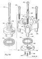
- Bolts 282 connect plug body 86 to plug holder 278.
- Plug holder 278 has a flange portion 280 which has an opening 286 for each of bolts 282.
- Flange 280 further has, for each opening 286, integral tubular stand-offs 288.
- Stand-offs 288 have lower ends 290 (see Figure 5A ) that rest on plug body top surface 90 so that the main flange portion 280 of plug holder 278 is held above leaves 258, 260.
- Plug holder 278 includes a rotatable actuating portion 292 that is received in an opening 294 in flange portion 280.
- a bearing 296 provides for the easy rotation of actuating portion 292.
- actuating portion 292 Affixed to a lower end of actuating portion 292 is a plate 298 held in place by screws 299 so that actuating portion 292 remains rotatably secure to flange portion 280.
- An O-ring gasket 308 provides a seal between flange portion 280 and plate 298.
- Extending downwardly from plate 298 are two opposed boss portions 300.
- a rod 306 extends through a central opening 304 of the actuating portion.
- leaves 258, 260 are pivotal on plug body top surface 90, each leaf pivoting about a pivot pin 266.
- Pivot pins 266 are bolts extending through openings in the leaves 258, 260.
- Formed in each of the leaves 258, 260 are an arcuate guide slot 268, a first plug holder bolt slot 274, a second plug holder bolt slot 276, and a cam surface slot 272.
- Each slot 268 is formed in an arc relative to pivot pin 266.
- Guide bolts 270 extend through slots 268 and into a threaded opening 284 in top surface 90 of plug body 86 (see Figure 5B ). The heads of bolts 270 maintain leaves 258, 260 in slidable contact with plug body top surface 90.
- First plug holder bolt slot 274 is arcuate about pivot pin 266.
- Second plug holder bolt slot 276 communicates with the straight inner edge 264 of leaf 258, 260.
- the slots 274, 276 receive bolts 282 and bolts 282 thread into threaded recesses 284 in the top surface 90 of plug body 86.
- the cam surface slot 272 is eccentric with respect to the axis of pivot of each leaf 258, 260 - that is, with respect to pivot pin 266 - and with respect to the rotational axis of actuating portion 292 of plug holder 278.
- Boss portions 300 of plug holder 278 engage cam surface slots 272, and the interaction of boss portions 300 and cam surface slots 272 moves leaves 258 and 260 between their collapsed and expanded positions. In this manner, direct mechanical coupling is employed to move the leaves 258, 260.
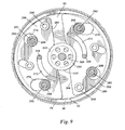
- Figure 3 shows the leaves 258, 260 in their collapsed position; their respective circumferential edge 262 is withdrawn within the confines of the external circumferential surface 82 of plug body 86.
- the closure member may be inserted into or removed from a cylindrical opening such as that formed by flange 60.
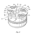
- Figure 4 shows the leaves 258, 260 in their expanded position; their respective circumferential edge 262 extends beyond the external circumferential surface 82 of plug body 86.
- the leaves 258, 260 extend into a circumferential groove 76 (see Figures 6 and 8 ), thereby locking the closure member in position within flange 60.
- plug holder 278 may be removed by unthreading the four bolts 282, thereby allowing a cover to be placed over flange 60.
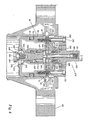
- Plug body 86 has a reduced diameter opening 236 extending downwardly toward a bottom surface 238 of plug body 86. Reduced opening 236 is flared out into a frusto-conical opening 240 that communicates with a cylindrical lower opening 242. Plug body 86 also has a larger diameter opening 162 that contains a cylindrical guide 234. Cylindrical guide 234 is directly interposed between the straight edges 264 of the leaves 258, 260.
- each leaf 258, 260 has a shallow-depth semicircular recess 302 therein, substantially equal to the thickness of the leaf 258, 260 (see Figures 3 and 4 ). Because of cylindrical guide 234, leaves 258, 260 cannot be retracted to their collapsed position without passageway 236 being open to relieve any pressure across plug body 86.
- a valve element has a stem portion 244 that is coaxially affixed to the bottom surface of a guide 234. Stem portion 244 integrally connects with a valve head portion 248 that has a frusto-conical valve sealing surface 250. Received in fiusto-conical opening 240 is a circumferential groove 252 that receives a seal 254. A downward force on rod 306 urges valve stem 244, and thereby valve head 248, to the lower or valve open condition. A spring 255 urges valve stem 244, and thereby valve head 248, to the upper or valve closed condition.
- valve head 248 When the leaves 258, 260 are in their expanded positions, spring bias valve head 248 is moved into a closed position closing passageway 236 through plug body 86.
- the upward movement of valve head 248 and stem 244 moves cylindrical guide 234 to an upward position as shown in Figure 9 .
- cylindrical guide 234 In this upward position, cylindrical guide 234 is positioned between the inner edges 264 of each of the plates 258, 260 thereby preventing the plates from moving from their expanded positions to their collapsed positions.
- Downward force on rod 306 depresses central guide 234 and thereby stem 244 having valve head 248 thereon to open a passage for fluid flow through opening 236 in plug body 86. The operator will know when flow through opening 236 ceases thereby indicating that pressure within flange 60 and above plug body 86 has been relieved.
- the operator When inserting and orienting the closure member, however, the operator needs a method to verify the closure member is in its expanded position.
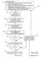
- the operator first establishes a set of pre-conditions 12 that includes installing tapping machine 100 onto sandwich valve 106, installing equalization piping 110, installing a tapping adapter (not shown) onto tapping machine 100, positioning the completion plug body 86 and plug holder 278 onto the boring bar (not shown) of tapping machine 100, and ensuring that leaves 258, 260 of completion plug body 86 are in the fully collapsed position.
- step 14 occurs in which equalization valve 112, tapping valve 116, sandwich valve 106, and the internal bypass valve 108 are each closed.
- Bleeder valve 104 remains open.
- Step 16 opens internal bypass valve 108 and records a pipeline pressure P-1 as indicated by pressure gauge 114.
- Step 18 opens tapping valve 116.
- Bleeder valve 104 then purges air from tapping machine 100.
- Step 20 closes bleeder valve 104 and records a tapping machine pressure P-2 as indicated by pressure gauge 102.
- a series of pressure checking steps, 22, 28, and an interrelated series of valve opening steps 24, 30 then occur.
- Pressure check 22 determines whether pressure P-1 equals pressure P-2. If the two pressures P-1, P-2 are equal, then step 24 opens equalization valve 112 and a second pressure check 28 takes place. However, if pressure check 22 shows that the two pressures P-1, P-2 are not equal, then trouble shooting step 26 is performed to determine and correct the cause of unequal pressures P-1, P-2. After equalization valve 112 has been opened in step 24, a second pressure check 28 is conducted. If the two pressures P-1, P-2 remain equal, then step 30 opens sandwich valve 106. If the two pressures P-1, P-2 are not equal, sandwich valve 106 remains closed and trouble shooting step 26 is again performed.
- lowering step 32 passes plug body 86 through sandwich valve 106 and into the cylindrical opening of fitting flange 60.
- a third pressure check 34 is performed prior to plug body 86 coming to a complete stop within fitting flange 60 to determine whether the two pressures P-1, P-2 are equal. If the pressures P-1, P-2, not equal, trouble-shooting step 26 is once again performed. If the two pressures P-1, P-2 are equal, then plug body 86 is further lowered in step 36 until plug body 86 comes to a complete stop on circumferential ledge 70 located on an inner surface flange 60 (see Figure 6 ).
- Step 38 orients plug body 86 so that leaves 258, 260 are in their expanded positions.
- a worm shaft (not shown) of tapping machine 100 is rotated in a clockwise direction, thereby rotating the boring bar and plug holder 278.
- Step 40 retracts the boring bar until resistance is felt to confirm leaves 258, 260 are in their expanded positions. If the leaves 258, 260 are in their expanded positions, then the upward travel of plug holder 278 is restricted. Step 42 releases plug holder 278, thereby closing the interlock.
- step 42 isolates equalization piping 110 from pipeline 52 by closing tapping valve 116 and equalization valve 112.
- step 46 opens bleeder valve 104 to purge air and pipeline product contained in tapping machine 100, thereby reducing pressure P-2 to 0 psi gauge.
- Step 48 retracts the boring bar fully and Step 50 removes tapping machine 100 and sandwich valve 106.
Claims (13)
- Verfahren zum Verifizieren eines Schließens eines Verriegelungssystems eines zylindrischen Durchgangs, wobei das Verriegelungssystem ein Abschluss-Steckstück (86) umfasst, welches einen oder mehrere Verriegelungsringe aufweist, wobei das Verfahren die Schritte umfasst:Isolieren einer Bohrmaschine (100) von einer Rohrleitung (52), um einen Produktstrom von dem Einen zu dem Anderen zu verhindern, wobei die Bohrmaschine (100) über eine Ausgleichsleitung (110) mit einem zweiten zylindrischen Durchgang verbunden ist und der zweite zylindrische Durchgang relativ zu einem Produktstrom der Rohrleitung (52) stromabwärts der Bohrmaschine (100) angeordnet ist;Ausgleichen eines Drucks der Bohrmaschine (100) und eines Drucks der Rohrleitung (52);Absenken des Abschluss-Steckstücks (86) von der Bohrmaschine (100) in einen zylindrischen Durchgang der Rohrleitung (52) bis eine nach unten gerichtete Bewegung des Abschluss-Steckstücks beschränkt wird;Orientieren des Abschluss-Steckstücks innerhalb des Durchgangs, so dass der Verriegelungsring in einer vollständig ausgedehnten Position ist; undAnheben des Abschluss-Steckstücks bis dessen nach oben gerichtete Bewegung innerhalb des Durchgangs beschränkt wird,wobei der Durchgang über ein Sandwich-Ventil (106) mit einer Bohrmaschine (100) verbunden ist, wobei das Sandwich-Ventil (106) ein internes Bypass-Ventil (108) aufweist.
- Verfahren nach Anspruch 1 ferner umfassend den Schritt eines Freigebens des Abschluss-Steckstücks, um den Verriegelungsring in der vollständig ausgedehnten Position zu halten.
- Verfahren nach Anspruch 1, wobei der Druck-Ausgleichs-Schritt ferner den Schritt umfasst, dem Produkt zu erlauben, zwischen der Rohrleitung (52) und der Bohrmaschine (100) zu strömen.
- Verfahren nach Anspruch 1, wobei der Druck-Ausgleichs-Schritt ferner den Schritt eines Reinigens im Wesentlichen der gesamten Luft, welche in der Bohrmaschine (100) enthalten ist, umfasst.
- Verfahren nach einem der vorhergehenden Ansprüche, ferner umfassend einen Druck-Reduzierungs-Schritt.
- Verfahren nach Anspruch 5, wobei der Druck-Reduzierungs-Schritt die Schritte umfasst: Isolieren der Rohrleitung (52) und der Bohrmaschine (100) voneinander für ein zweites Mal, um einen Produktstrom von dem Einen zu dem Aanderen zu verhindern; und Abführen im Wesentlichen der gesamten Luft, welche in der Bohrmaschine (100) enthalten ist, so dass der Druck der Bohrmaschine (100) einen Wert von 0 psi annimt.
- Verfahren nach Anspruch 1 ferner umfassend den Schritt eines Isolierens der Bohrmaschine (100) von der Ausgleichsleitung (110), um einen Produktstrom von Einem zu dem Anderen zu verhindern.
- Verfahren nach Anspruch 1 ferner umfassend den Schritt eines Erlaubens, dass ein Produkt zwischen der Ausgleichsleitung (110) und der Bohrmaschine (100) strömt.
- Verfahren nach einem der vorhergehenden Ansprüche, wobei der Absenk-Schritt die Schritte umfasst: Anbringen eines Abschluss-Steckstücks an eine Bohrstange der Bohrmaschine (100); Öffnen des Sandwich-Ventils (106), um auf den zylindrischen Durchgang zuzugreifen; und Durchführen des Abschluss-Steckstücks durch das Sandwich-Ventil (106) und in einen Abschnitt des zylindrischen Durchgangs.
- Verfahren nach Anspruch 9, wobei der zylindrische Durchgang einen umlaufenden Absatz (70) umfasst, welcher eine fortgeführte, nach unten gerichtete Bewegung des Abschluss-Steckstücks durch den Durchgang verhindert.
- Verfahren nach Anspruch 1, wobei der Orientierungs-Schritt den Schritt eines Rotierens des Abschluss-Steckstücks, und in eine umlaufende Nut (76), welche an einer Innenfläche des Durchgangs angeordnet ist, umfasst.
- Verfahren nach einem der vorhergehenden Ansprüche, wobei der Anhebe-Schritt den Schritt eines Rotierens des Abschluss-Steckstücks für ein zweites Mal umfasst, um das Abschluss-Steckstück zu veranlassen, sich innerhalb des Durchgangs nach oben zu bewegen.
- Verfahren nach einem der vorhergehenden Ansprüche, wobei der Verriegelungsring ein Rückhalteblatt (258, 260) ist.
Priority Applications (1)
| Application Number | Priority Date | Filing Date | Title |
|---|---|---|---|
| PL09763255T PL2286136T3 (pl) | 2008-06-09 | 2009-05-28 | Weryfikowalny system zamykania i blokowania cylindrycznego przejścia |
Applications Claiming Priority (2)
| Application Number | Priority Date | Filing Date | Title |
|---|---|---|---|
| US12/135,831 US8001988B2 (en) | 2008-06-09 | 2008-06-09 | Verifiable closing and locking system of a cylindrical passageway |
| PCT/US2009/045426 WO2009151964A1 (en) | 2008-06-09 | 2009-05-28 | Verifiable closing and locking system of a cylindrical passageway |
Publications (3)
| Publication Number | Publication Date |
|---|---|
| EP2286136A1 EP2286136A1 (de) | 2011-02-23 |
| EP2286136A4 EP2286136A4 (de) | 2013-08-14 |
| EP2286136B1 true EP2286136B1 (de) | 2015-07-22 |
Family
ID=41399183
Family Applications (1)
| Application Number | Title | Priority Date | Filing Date |
|---|---|---|---|
| EP09763255.8A Active EP2286136B1 (de) | 2008-06-09 | 2009-05-28 | Überprüfbares verschluss- und versiegelungssystem für einen zylinderförmigen durchgang |
Country Status (24)
| Country | Link |
|---|---|
| US (1) | US8001988B2 (de) |
| EP (1) | EP2286136B1 (de) |
| JP (1) | JP5680531B2 (de) |
| KR (1) | KR101615508B1 (de) |
| CN (1) | CN102057206B (de) |
| AR (1) | AR072017A1 (de) |
| AU (1) | AU2009257768B2 (de) |
| BR (1) | BRPI0914883A2 (de) |
| CA (1) | CA2725668C (de) |
| CO (1) | CO6331385A2 (de) |
| DK (1) | DK2286136T3 (de) |
| EA (1) | EA019868B1 (de) |
| ES (1) | ES2544823T3 (de) |
| HU (1) | HUE026411T2 (de) |
| IL (1) | IL209684A (de) |
| JO (1) | JO2638B1 (de) |
| MX (1) | MX2010013540A (de) |
| MY (1) | MY155430A (de) |
| PE (1) | PE20100103A1 (de) |
| PL (1) | PL2286136T3 (de) |
| PT (1) | PT2286136E (de) |
| RS (1) | RS54178B1 (de) |
| WO (1) | WO2009151964A1 (de) |
| ZA (1) | ZA201008822B (de) |
Families Citing this family (10)
| Publication number | Priority date | Publication date | Assignee | Title |
|---|---|---|---|---|
| AU2015201842B2 (en) * | 2008-04-28 | 2017-04-27 | Aker Subsea As | Internal tree cap and ITC running tool |
| US20110240156A1 (en) * | 2010-04-01 | 2011-10-06 | Lounis Azibi | Double Block and Bleed Sandwich-Type Valve |
| DK2593705T3 (en) * | 2012-01-23 | 2015-08-24 | Tdw Delaware Inc | Machine activated and removable safety closure with antirotations- and machine error holder |
| RU2518787C1 (ru) * | 2013-05-06 | 2014-06-10 | ЗАО "Аэрокосмический мониторинг и технологии" | Способ определения срока службы трубопровода |
| CN105987253B (zh) * | 2015-01-29 | 2019-01-25 | 上海乾恒实业有限公司 | 油气管道封堵方法 |
| GB2540214B (en) * | 2015-07-10 | 2020-12-30 | Stats Uk Ltd | Completion Plug Assembly & Method |
| DE202017104929U1 (de) * | 2017-08-16 | 2018-11-19 | Rosen Swiss Ag | Verschlussvorrichtung |
| US10443586B1 (en) | 2018-09-12 | 2019-10-15 | Douglas A Sahm | Fluid transfer and depressurization system |
| ES2943557T3 (es) | 2019-03-07 | 2023-06-14 | Tdw Delaware Inc | Sistema de mantenimiento de tuberías de polietileno que incluye medios de conexión rápida para operaciones de derivación, taponamiento y terminación de tuberías de polietileno |
| CN109931010A (zh) * | 2019-04-15 | 2019-06-25 | 成都百胜野牛科技有限公司 | 转接装置、井口装置及组装方法 |
Family Cites Families (37)
| Publication number | Priority date | Publication date | Assignee | Title |
|---|---|---|---|---|
| GB263367A (en) * | 1926-04-09 | 1926-12-30 | Lorenzo Bartlett Cleaves | Improvements in pipe connections and pressure tapping devices |
| US2010200A (en) | 1932-11-17 | 1935-08-06 | Internat Carbonic Engineering | Sealing device for pressure containers |
| US2287750A (en) | 1939-10-30 | 1942-06-23 | William B Clayton | Fill pipe cap |
| US2281145A (en) | 1939-11-28 | 1942-04-28 | Duey Harold Stewart | Pipe plug |
| US2431778A (en) | 1946-03-22 | 1947-12-02 | Frank F Sosaya | Test cap |
| US2512041A (en) | 1949-03-02 | 1950-06-20 | Steele Gilbert | Temporary drainpipe closure |
| US3047266A (en) | 1957-12-18 | 1962-07-31 | Williamson Inc T | Valve |
| US3155116A (en) | 1962-06-04 | 1964-11-03 | Williamson Inc T | Apparatus for closing side openings into pipelines |
| US3114528A (en) | 1962-11-07 | 1963-12-17 | Lester W Forest | Base and lock assembly for pipe |
| US3179446A (en) | 1963-11-04 | 1965-04-20 | Dresser Ind | Extension fitting having initial flexible lip seal gasket |
| US3483894A (en) | 1966-04-07 | 1969-12-16 | Us Navy | High pressure pipe test plug |
| US3765456A (en) | 1972-04-17 | 1973-10-16 | Anchor Equip Co | Chemical cleaning line connector |
| US3766947A (en) | 1972-06-05 | 1973-10-23 | Williamson Inc T | Fluid tight closure |
| US4144909A (en) | 1975-06-25 | 1979-03-20 | Team, Inc. | Apparatus for closing side openings into pipelines |
| US3991791A (en) | 1975-11-24 | 1976-11-16 | Mueller Co. | Bayonet-type closure for line stopper fittings |
| JPS6216552Y2 (de) * | 1980-07-03 | 1987-04-25 | ||
| US4377185A (en) | 1980-12-18 | 1983-03-22 | Tubeco, Inc. | Hydrotest apparatus |
| US4387740A (en) | 1981-05-15 | 1983-06-14 | T. D. Williamson, Inc. | Cam-flange |
| US4466550A (en) | 1982-09-28 | 1984-08-21 | T. D. Williamson, Inc. | Closure for a cylindrical opening having improved venting means |
| US4576778A (en) | 1983-08-17 | 1986-03-18 | Westinghouse Electric Corp. | Core barrel plug |
| US4609209A (en) | 1983-11-07 | 1986-09-02 | T. D. Williamson, Inc. | Precise alignment adapter flange |
| US4902043A (en) | 1985-09-17 | 1990-02-20 | John T. Hoskins | Fluid coupling and seal assembly |
| US5038830A (en) | 1986-06-27 | 1991-08-13 | Hydrotreat, Inc. | Pipe and sealing device |
| US4693278A (en) | 1986-11-10 | 1987-09-15 | T. D. Williamson, Inc. | Safety closure member |
| US4880028A (en) | 1989-02-03 | 1989-11-14 | Tdw Delaware, Inc. | Completion machine |
| US5035266A (en) | 1989-12-11 | 1991-07-30 | Cherne Industries Incorporated | Mechanical plug for clean-out tees |
| US5450765A (en) | 1994-03-01 | 1995-09-19 | Tdw Delaware, Inc. | Apparatus for providing signal communication between the interior and exterior of a pipeline |
| US5437309A (en) | 1994-03-15 | 1995-08-01 | Timmons; Robert D. | Lockable well cap |
| US5439331A (en) | 1994-03-31 | 1995-08-08 | Tdw Delaware, Inc. | High pressure tapping apparatus |
| FR2744194B1 (fr) * | 1996-01-29 | 1998-04-10 | Sabla Sa | Dispositif, du type couramment denomme "robinet de prise en charge" |
| US6012878A (en) | 1997-12-02 | 2000-01-11 | Tdw Delaware, Inc. | Pressure balanced subsea tapping machine |
| US5975142A (en) | 1998-08-10 | 1999-11-02 | Tdw Delaware, Inc. | Removable closure system |
| US6286553B1 (en) | 2000-09-01 | 2001-09-11 | Tdw Delaware, Inc. | Removable closure system |
| US6648562B1 (en) | 2001-06-08 | 2003-11-18 | Charles D. Calkins | Apparatus for tapping a hole in a pipeline |
| US7270139B2 (en) * | 2005-04-25 | 2007-09-18 | Tdw Delaware, Inc. | Cam-assisted, wedge actuated, metal-to-metal seal, block and bleed plugging tool |
| US7353839B2 (en) | 2005-05-19 | 2008-04-08 | Tdw Delaware, Inc. | High temperature completion plug |
| US7311114B2 (en) * | 2005-05-20 | 2007-12-25 | Tdw Delaware, Inc. | Cross-line plugging system |
-
2008
- 2008-06-09 US US12/135,831 patent/US8001988B2/en active Active
-
2009
- 2009-05-28 AU AU2009257768A patent/AU2009257768B2/en active Active
- 2009-05-28 KR KR1020107027497A patent/KR101615508B1/ko active IP Right Grant
- 2009-05-28 PL PL09763255T patent/PL2286136T3/pl unknown
- 2009-05-28 RS RS20150566A patent/RS54178B1/en unknown
- 2009-05-28 CN CN200980121560XA patent/CN102057206B/zh active Active
- 2009-05-28 EA EA201001726A patent/EA019868B1/ru unknown
- 2009-05-28 DK DK09763255.8T patent/DK2286136T3/en active
- 2009-05-28 PT PT97632558T patent/PT2286136E/pt unknown
- 2009-05-28 EP EP09763255.8A patent/EP2286136B1/de active Active
- 2009-05-28 MY MYPI2010005800A patent/MY155430A/en unknown
- 2009-05-28 WO PCT/US2009/045426 patent/WO2009151964A1/en active Application Filing
- 2009-05-28 HU HUE09763255A patent/HUE026411T2/en unknown
- 2009-05-28 MX MX2010013540A patent/MX2010013540A/es unknown
- 2009-05-28 BR BRPI0914883A patent/BRPI0914883A2/pt not_active IP Right Cessation
- 2009-05-28 CA CA2725668A patent/CA2725668C/en active Active
- 2009-05-28 ES ES09763255.8T patent/ES2544823T3/es active Active
- 2009-05-28 JP JP2011513551A patent/JP5680531B2/ja active Active
- 2009-06-03 JO JO2009202A patent/JO2638B1/en active
- 2009-06-05 AR ARP090102032 patent/AR072017A1/es active IP Right Grant
- 2009-06-09 PE PE2009000808A patent/PE20100103A1/es not_active Application Discontinuation
-
2010
- 2010-12-01 IL IL20968410A patent/IL209684A/en not_active IP Right Cessation
- 2010-12-08 ZA ZA2010/08822A patent/ZA201008822B/en unknown
- 2010-12-14 CO CO10156969A patent/CO6331385A2/es active IP Right Grant
Also Published As
| Publication number | Publication date |
|---|---|
| BRPI0914883A2 (pt) | 2015-11-24 |
| AU2009257768B2 (en) | 2013-03-07 |
| MY155430A (en) | 2015-10-15 |
| AU2009257768A1 (en) | 2009-12-17 |
| JP5680531B2 (ja) | 2015-03-04 |
| ES2544823T3 (es) | 2015-09-04 |
| WO2009151964A1 (en) | 2009-12-17 |
| EP2286136A1 (de) | 2011-02-23 |
| CA2725668A1 (en) | 2009-12-17 |
| MX2010013540A (es) | 2011-04-26 |
| IL209684A (en) | 2013-09-30 |
| EA019868B1 (ru) | 2014-06-30 |
| EA201001726A1 (ru) | 2011-06-30 |
| CA2725668C (en) | 2016-08-23 |
| JO2638B1 (en) | 2012-06-17 |
| DK2286136T3 (en) | 2015-10-26 |
| PL2286136T3 (pl) | 2015-12-31 |
| US8001988B2 (en) | 2011-08-23 |
| CN102057206B (zh) | 2013-01-02 |
| CN102057206A (zh) | 2011-05-11 |
| PT2286136E (pt) | 2015-09-24 |
| US20090301568A1 (en) | 2009-12-10 |
| KR20110026419A (ko) | 2011-03-15 |
| RS54178B1 (en) | 2015-12-31 |
| EP2286136A4 (de) | 2013-08-14 |
| PE20100103A1 (es) | 2010-02-26 |
| JP2011523006A (ja) | 2011-08-04 |
| IL209684A0 (en) | 2011-02-28 |
| ZA201008822B (en) | 2011-08-31 |
| CO6331385A2 (es) | 2011-10-20 |
| AR072017A1 (es) | 2010-07-28 |
| HUE026411T2 (en) | 2016-06-28 |
| KR101615508B1 (ko) | 2016-04-26 |
Similar Documents
| Publication | Publication Date | Title |
|---|---|---|
| EP2286136B1 (de) | Überprüfbares verschluss- und versiegelungssystem für einen zylinderförmigen durchgang | |
| EP1325259B1 (de) | Einrichtung zum vorübergehenden schliessen einer zylindrischen öffnung | |
| US4693278A (en) | Safety closure member | |
| DK2593705T3 (en) | Machine activated and removable safety closure with antirotations- and machine error holder | |
| NO176774B (no) | Reguleringsventil for bruk ved brönntesting | |
| GB1574953A (en) | Valve apparatus and method for controlling a well | |
| AU2012258298A1 (en) | Machine-actuated and removable safety closure with anti-rotation and machine-released holder | |
| US9234393B2 (en) | Bore selector | |
| EP0647301B1 (de) | Druckentlastungsventil | |
| AU2019200477A1 (en) | Automated pressure equalization above and below completion plug of gate valve cartridge or a completion plug of a line stop fitting | |
| CN116951143B (zh) | 一种螺纹式安全阀 |
Legal Events
| Date | Code | Title | Description |
|---|---|---|---|
| PUAI | Public reference made under article 153(3) epc to a published international application that has entered the european phase |
Free format text: ORIGINAL CODE: 0009012 |
|
| 17P | Request for examination filed |
Effective date: 20101122 |
|
| AK | Designated contracting states |
Kind code of ref document: A1 Designated state(s): AT BE BG CH CY CZ DE DK EE ES FI FR GB GR HR HU IE IS IT LI LT LU LV MC MK MT NL NO PL PT RO SE SI SK TR |
|
| AX | Request for extension of the european patent |
Extension state: AL BA RS |
|
| A4 | Supplementary search report drawn up and despatched |
Effective date: 20130712 |
|
| RIC1 | Information provided on ipc code assigned before grant |
Ipc: F16L 55/10 20060101AFI20130708BHEP Ipc: F16L 41/04 20060101ALI20130708BHEP |
|
| 17Q | First examination report despatched |
Effective date: 20140129 |
|
| GRAP | Despatch of communication of intention to grant a patent |
Free format text: ORIGINAL CODE: EPIDOSNIGR1 |
|
| INTG | Intention to grant announced |
Effective date: 20150216 |
|
| GRAS | Grant fee paid |
Free format text: ORIGINAL CODE: EPIDOSNIGR3 |
|
| GRAA | (expected) grant |
Free format text: ORIGINAL CODE: 0009210 |
|
| AK | Designated contracting states |
Kind code of ref document: B1 Designated state(s): AT BE BG CH CY CZ DE DK EE ES FI FR GB GR HR HU IE IS IT LI LT LU LV MC MK MT NL NO PL PT RO SE SI SK TR |
|
| AX | Request for extension of the european patent |
Extension state: AL BA RS |
|
| REG | Reference to a national code |
Ref country code: GB Ref legal event code: FG4D |
|
| REG | Reference to a national code |
Ref country code: CH Ref legal event code: EP |
|
| REG | Reference to a national code |
Ref country code: IE Ref legal event code: FG4D |
|
| REG | Reference to a national code |
Ref country code: AT Ref legal event code: REF Ref document number: 738124 Country of ref document: AT Kind code of ref document: T Effective date: 20150815 |
|
| REG | Reference to a national code |
Ref country code: NL Ref legal event code: T3 |
|
| REG | Reference to a national code |
Ref country code: DE Ref legal event code: R096 Ref document number: 602009032378 Country of ref document: DE |
|
| REG | Reference to a national code |
Ref country code: ES Ref legal event code: FG2A Ref document number: 2544823 Country of ref document: ES Kind code of ref document: T3 Effective date: 20150904 |
|
| REG | Reference to a national code |
Ref country code: PT Ref legal event code: SC4A Free format text: AVAILABILITY OF NATIONAL TRANSLATION Effective date: 20150825 |
|
| REG | Reference to a national code |
Ref country code: RO Ref legal event code: EPE |
|
| REG | Reference to a national code |
Ref country code: DK Ref legal event code: T3 Effective date: 20151020 |
|
| REG | Reference to a national code |
Ref country code: SE Ref legal event code: TRGR |
|
| REG | Reference to a national code |
Ref country code: NO Ref legal event code: T2 Effective date: 20150722 |
|
| REG | Reference to a national code |
Ref country code: GR Ref legal event code: EP Ref document number: 20150401841 Country of ref document: GR Effective date: 20151022 |
|
| REG | Reference to a national code |
Ref country code: LT Ref legal event code: MG4D |
|
| REG | Reference to a national code |
Ref country code: PL Ref legal event code: T3 |
|
| PG25 | Lapsed in a contracting state [announced via postgrant information from national office to epo] |
Ref country code: LT Free format text: LAPSE BECAUSE OF FAILURE TO SUBMIT A TRANSLATION OF THE DESCRIPTION OR TO PAY THE FEE WITHIN THE PRESCRIBED TIME-LIMIT Effective date: 20150722 Ref country code: FI Free format text: LAPSE BECAUSE OF FAILURE TO SUBMIT A TRANSLATION OF THE DESCRIPTION OR TO PAY THE FEE WITHIN THE PRESCRIBED TIME-LIMIT Effective date: 20150722 Ref country code: LV Free format text: LAPSE BECAUSE OF FAILURE TO SUBMIT A TRANSLATION OF THE DESCRIPTION OR TO PAY THE FEE WITHIN THE PRESCRIBED TIME-LIMIT Effective date: 20150722 |
|
| PG25 | Lapsed in a contracting state [announced via postgrant information from national office to epo] |
Ref country code: IS Free format text: LAPSE BECAUSE OF FAILURE TO SUBMIT A TRANSLATION OF THE DESCRIPTION OR TO PAY THE FEE WITHIN THE PRESCRIBED TIME-LIMIT Effective date: 20151122 Ref country code: HR Free format text: LAPSE BECAUSE OF FAILURE TO SUBMIT A TRANSLATION OF THE DESCRIPTION OR TO PAY THE FEE WITHIN THE PRESCRIBED TIME-LIMIT Effective date: 20150722 |
|
| REG | Reference to a national code |
Ref country code: DE Ref legal event code: R097 Ref document number: 602009032378 Country of ref document: DE |
|
| PG25 | Lapsed in a contracting state [announced via postgrant information from national office to epo] |
Ref country code: EE Free format text: LAPSE BECAUSE OF FAILURE TO SUBMIT A TRANSLATION OF THE DESCRIPTION OR TO PAY THE FEE WITHIN THE PRESCRIBED TIME-LIMIT Effective date: 20150722 Ref country code: SK Free format text: LAPSE BECAUSE OF FAILURE TO SUBMIT A TRANSLATION OF THE DESCRIPTION OR TO PAY THE FEE WITHIN THE PRESCRIBED TIME-LIMIT Effective date: 20150722 |
|
| PLBE | No opposition filed within time limit |
Free format text: ORIGINAL CODE: 0009261 |
|
| STAA | Information on the status of an ep patent application or granted ep patent |
Free format text: STATUS: NO OPPOSITION FILED WITHIN TIME LIMIT |
|
| REG | Reference to a national code |
Ref country code: FR Ref legal event code: PLFP Year of fee payment: 8 |
|
| REG | Reference to a national code |
Ref country code: HU Ref legal event code: AG4A Ref document number: E026411 Country of ref document: HU |
|
| 26N | No opposition filed |
Effective date: 20160425 |
|
| PG25 | Lapsed in a contracting state [announced via postgrant information from national office to epo] |
Ref country code: SI Free format text: LAPSE BECAUSE OF FAILURE TO SUBMIT A TRANSLATION OF THE DESCRIPTION OR TO PAY THE FEE WITHIN THE PRESCRIBED TIME-LIMIT Effective date: 20150722 |
|
| PG25 | Lapsed in a contracting state [announced via postgrant information from national office to epo] |
Ref country code: LU Free format text: LAPSE BECAUSE OF FAILURE TO SUBMIT A TRANSLATION OF THE DESCRIPTION OR TO PAY THE FEE WITHIN THE PRESCRIBED TIME-LIMIT Effective date: 20160528 |
|
| REG | Reference to a national code |
Ref country code: CH Ref legal event code: PL |
|
| REG | Reference to a national code |
Ref country code: DK Ref legal event code: EBP Effective date: 20160531 |
|
| REG | Reference to a national code |
Ref country code: NL Ref legal event code: MM Effective date: 20160601 |
|
| PG25 | Lapsed in a contracting state [announced via postgrant information from national office to epo] |
Ref country code: RO Free format text: LAPSE BECAUSE OF NON-PAYMENT OF DUE FEES Effective date: 20150722 Ref country code: CH Free format text: LAPSE BECAUSE OF NON-PAYMENT OF DUE FEES Effective date: 20160531 Ref country code: LI Free format text: LAPSE BECAUSE OF NON-PAYMENT OF DUE FEES Effective date: 20160531 Ref country code: CZ Free format text: LAPSE BECAUSE OF NON-PAYMENT OF DUE FEES Effective date: 20160528 |
|
| REG | Reference to a national code |
Ref country code: GR Ref legal event code: ML Ref document number: 20150401841 Country of ref document: GR Effective date: 20161207 |
|
| REG | Reference to a national code |
Ref country code: IE Ref legal event code: MM4A |
|
| PG25 | Lapsed in a contracting state [announced via postgrant information from national office to epo] |
Ref country code: NL Free format text: LAPSE BECAUSE OF NON-PAYMENT OF DUE FEES Effective date: 20160601 Ref country code: SE Free format text: LAPSE BECAUSE OF NON-PAYMENT OF DUE FEES Effective date: 20160529 Ref country code: GR Free format text: LAPSE BECAUSE OF NON-PAYMENT OF DUE FEES Effective date: 20161207 |
|
| PG25 | Lapsed in a contracting state [announced via postgrant information from national office to epo] |
Ref country code: HU Free format text: LAPSE BECAUSE OF NON-PAYMENT OF DUE FEES Effective date: 20160529 |
|
| REG | Reference to a national code |
Ref country code: FR Ref legal event code: PLFP Year of fee payment: 9 |
|
| PG25 | Lapsed in a contracting state [announced via postgrant information from national office to epo] |
Ref country code: PT Free format text: LAPSE BECAUSE OF NON-PAYMENT OF DUE FEES Effective date: 20170228 Ref country code: DK Free format text: LAPSE BECAUSE OF NON-PAYMENT OF DUE FEES Effective date: 20160531 Ref country code: IE Free format text: LAPSE BECAUSE OF NON-PAYMENT OF DUE FEES Effective date: 20160528 |
|
| REG | Reference to a national code |
Ref country code: AT Ref legal event code: UEP Ref document number: 738124 Country of ref document: AT Kind code of ref document: T Effective date: 20150722 |
|
| REG | Reference to a national code |
Ref country code: AT Ref legal event code: MM01 Ref document number: 738124 Country of ref document: AT Kind code of ref document: T Effective date: 20160528 |
|
| PG25 | Lapsed in a contracting state [announced via postgrant information from national office to epo] |
Ref country code: AT Free format text: LAPSE BECAUSE OF NON-PAYMENT OF DUE FEES Effective date: 20160528 |
|
| PG25 | Lapsed in a contracting state [announced via postgrant information from national office to epo] |
Ref country code: PL Free format text: LAPSE BECAUSE OF NON-PAYMENT OF DUE FEES Effective date: 20160528 |
|
| REG | Reference to a national code |
Ref country code: FR Ref legal event code: PLFP Year of fee payment: 10 |
|
| PG25 | Lapsed in a contracting state [announced via postgrant information from national office to epo] |
Ref country code: CY Free format text: LAPSE BECAUSE OF FAILURE TO SUBMIT A TRANSLATION OF THE DESCRIPTION OR TO PAY THE FEE WITHIN THE PRESCRIBED TIME-LIMIT Effective date: 20150722 |
|
| PG25 | Lapsed in a contracting state [announced via postgrant information from national office to epo] |
Ref country code: MK Free format text: LAPSE BECAUSE OF FAILURE TO SUBMIT A TRANSLATION OF THE DESCRIPTION OR TO PAY THE FEE WITHIN THE PRESCRIBED TIME-LIMIT Effective date: 20150722 Ref country code: MC Free format text: LAPSE BECAUSE OF FAILURE TO SUBMIT A TRANSLATION OF THE DESCRIPTION OR TO PAY THE FEE WITHIN THE PRESCRIBED TIME-LIMIT Effective date: 20150722 Ref country code: MT Free format text: LAPSE BECAUSE OF NON-PAYMENT OF DUE FEES Effective date: 20160531 |
|
| PG25 | Lapsed in a contracting state [announced via postgrant information from national office to epo] |
Ref country code: BG Free format text: LAPSE BECAUSE OF FAILURE TO SUBMIT A TRANSLATION OF THE DESCRIPTION OR TO PAY THE FEE WITHIN THE PRESCRIBED TIME-LIMIT Effective date: 20150722 |
|
| P01 | Opt-out of the competence of the unified patent court (upc) registered |
Effective date: 20230609 |
|
| PGFP | Annual fee paid to national office [announced via postgrant information from national office to epo] |
Ref country code: NO Payment date: 20230516 Year of fee payment: 15 Ref country code: IT Payment date: 20230524 Year of fee payment: 15 Ref country code: FR Payment date: 20230516 Year of fee payment: 15 Ref country code: ES Payment date: 20230609 Year of fee payment: 15 Ref country code: DE Payment date: 20230524 Year of fee payment: 15 |
|
| PGFP | Annual fee paid to national office [announced via postgrant information from national office to epo] |
Ref country code: TR Payment date: 20230518 Year of fee payment: 15 |
|
| PGFP | Annual fee paid to national office [announced via postgrant information from national office to epo] |
Ref country code: BE Payment date: 20230511 Year of fee payment: 15 |
|
| PGFP | Annual fee paid to national office [announced via postgrant information from national office to epo] |
Ref country code: GB Payment date: 20230518 Year of fee payment: 15 |