EP2286122B1 - Apparatus and methods to couple actuator stems and rod end bearings - Google Patents
Apparatus and methods to couple actuator stems and rod end bearings Download PDFInfo
- Publication number
- EP2286122B1 EP2286122B1 EP09743211A EP09743211A EP2286122B1 EP 2286122 B1 EP2286122 B1 EP 2286122B1 EP 09743211 A EP09743211 A EP 09743211A EP 09743211 A EP09743211 A EP 09743211A EP 2286122 B1 EP2286122 B1 EP 2286122B1
- Authority
- EP
- European Patent Office
- Prior art keywords
- actuator stem
- rod end
- control valve
- actuator
- bearing
- Prior art date
- Legal status (The legal status is an assumption and is not a legal conclusion. Google has not performed a legal analysis and makes no representation as to the accuracy of the status listed.)
- Active
Links
Images

Classifications
-
- F—MECHANICAL ENGINEERING; LIGHTING; HEATING; WEAPONS; BLASTING
- F16—ENGINEERING ELEMENTS AND UNITS; GENERAL MEASURES FOR PRODUCING AND MAINTAINING EFFECTIVE FUNCTIONING OF MACHINES OR INSTALLATIONS; THERMAL INSULATION IN GENERAL
- F16K—VALVES; TAPS; COCKS; ACTUATING-FLOATS; DEVICES FOR VENTING OR AERATING
- F16K31/00—Actuating devices; Operating means; Releasing devices
- F16K31/12—Actuating devices; Operating means; Releasing devices actuated by fluid
- F16K31/16—Actuating devices; Operating means; Releasing devices actuated by fluid with a mechanism, other than pulling-or pushing-rod, between fluid motor and closure member
- F16K31/165—Actuating devices; Operating means; Releasing devices actuated by fluid with a mechanism, other than pulling-or pushing-rod, between fluid motor and closure member the fluid acting on a diaphragm
-
- F—MECHANICAL ENGINEERING; LIGHTING; HEATING; WEAPONS; BLASTING
- F16—ENGINEERING ELEMENTS AND UNITS; GENERAL MEASURES FOR PRODUCING AND MAINTAINING EFFECTIVE FUNCTIONING OF MACHINES OR INSTALLATIONS; THERMAL INSULATION IN GENERAL
- F16C—SHAFTS; FLEXIBLE SHAFTS; ELEMENTS OR CRANKSHAFT MECHANISMS; ROTARY BODIES OTHER THAN GEARING ELEMENTS; BEARINGS
- F16C7/00—Connecting-rods or like links pivoted at both ends; Construction of connecting-rod heads
- F16C7/02—Constructions of connecting-rods with constant length
-
- F—MECHANICAL ENGINEERING; LIGHTING; HEATING; WEAPONS; BLASTING
- F16—ENGINEERING ELEMENTS AND UNITS; GENERAL MEASURES FOR PRODUCING AND MAINTAINING EFFECTIVE FUNCTIONING OF MACHINES OR INSTALLATIONS; THERMAL INSULATION IN GENERAL
- F16K—VALVES; TAPS; COCKS; ACTUATING-FLOATS; DEVICES FOR VENTING OR AERATING
- F16K31/00—Actuating devices; Operating means; Releasing devices
- F16K31/12—Actuating devices; Operating means; Releasing devices actuated by fluid
- F16K31/16—Actuating devices; Operating means; Releasing devices actuated by fluid with a mechanism, other than pulling-or pushing-rod, between fluid motor and closure member
- F16K31/165—Actuating devices; Operating means; Releasing devices actuated by fluid with a mechanism, other than pulling-or pushing-rod, between fluid motor and closure member the fluid acting on a diaphragm
- F16K31/1655—Actuating devices; Operating means; Releasing devices actuated by fluid with a mechanism, other than pulling-or pushing-rod, between fluid motor and closure member the fluid acting on a diaphragm for rotating valves
Definitions
- This disclosure relates generally to control valves and, more particularly, to apparatus and methods to couple actuator stems and rod end bearings.
- a rotary control valve typically includes an actuator (e.g., a pneumatic actuator, an electric actuator, a hydraulic actuator, etc.) operatively coupled to a shaft extending from a rotary valve via a lever.
- the lever converts a rectilinear displacement of an actuator stem into a rotational displacement of the valve shaft.
- rotation of the lever causes the valve shaft and a flow control member (e.g., a disk, a ball, etc.) coupled to the valve shaft to rotate to increase or restrict the flow of fluid through the valve.
- a rod end bearing is typically employed.
- the rod end bearing may include an internally threaded bore (i.e., a female connection) that threadably receives an externally threaded end (i.e., a male connection) of the actuator stem.
- the rod end bearing may include an externally threaded end that threadably couples to an internally threaded bore of the actuator stem.
- the externally threaded portion of the rod end bearing and/or the actuator stem is typically formed by machining bar stock.
- a control valve in one example, includes an actuator disposed within a housing having a diaphragm captured between a first actuator casing and a second actuator casing.
- An actuator stem has a first end and a second end that each include an internally threaded bore, in which the first end of the actuator stem operatively couples to the diaphragm.
- the control valve further includes the following assembly according to claim 1.
- An assembly for use with a control valve includes a bearing having a body and a portion extending from the body, in which the portion includes an internally threaded bore, and an actuator stem having a first end that includes an internally threaded bore.
- An externally threaded stud threadably engages the bores of the rod end bearing and the actuator stem to couple the rod end bearing and the actuator stem.
- the portion has an internally threaded bore and tapered surface which mates with a tapered surface of the bore of the actuator stem.
- a method given in claim 10 discloses how to couple a rod end bearing and an actuator stem includes obtaining a rod end bearing having a portion with an internally threaded bore and an actuator stem having an internally threaded bore at a first end and coupling the rod end bearing to the actuator stem via an externally threaded stud.
- the portion and actuator stem having tapered surfaces as discussed above.
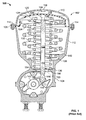
- FIG. 1 illustrates a known example rotary control valve having an externally threaded rod end bearing coupled to an internally threaded bore of an actuator stem.
- FIG. 2 illustrates an example rod end bearing and actuator stem connection described herein.
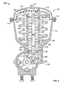
- FIG. 3 illustrates the example rotary control valve implemented with the example rod end bearing and actuator stem connection illustrated in FIG. 2 .
- the example methods and apparatus described herein provide increased strength to a connection between a rod end bearing and an actuator stem of a control valve.
- the example method and apparatus include an externally threaded stud that couples a rod end bearing to an actuator stem.
- Each of the rod end bearing and the actuator stem includes an end having an internally threaded bore to receive the externally threaded stud.
- the example methods and apparatus described herein advantageously replace coupling mechanisms that use an externally threaded rod end bearing end or, alternatively, an externally threaded end of an actuator stem, which, as noted above, are typically formed by machining away the higher strength material concentrated near the outer surface of a bar stock.
- the example rod end bearing end actuator stem connection described herein provides greater strength to resist loads (e.g., torsional loads) transmitted to the rod end bearing and actuator stem connection during assembly and/or disassembly of the control valve.
- the rod end bearing and actuator stem connection described herein substantially reduces twist off or fracture due to inadvertent over torquing or tightening of a fastener when coupling a diaphragm plate to and/or removing a diaphragm plate from the end of the actuator stem opposite the end coupled to the rod end bearing.
- FIG. 1 is a cross-sectional view of a known rotary control valve assembly 100.
- the example rotary control valve assembly 100 includes an actuator 102 coupled to a housing 104 of the rotary control valve 100.
- the actuator 102 includes a casing 106 that captures a diaphragm 108 between an upper casing portion 110 and a lower casing portion 112.
- the casing portions 110 and 112 are coupled together with a plurality of threaded fasteners 114 spaced along an outer edge of the casing 106.
- the diaphragm 108 separates the space within the casing 106 into a control pressure chamber 116 through which a controlled pressure is supplied via an inlet port 118 to displace the diaphragm 108.
- a diaphragm plate 120 couples the diaphragm 108 to an actuator stem or diaphragm rod 122 and provides a rigid backing for the diaphragm 108.
- the actuator stem 122 includes a first end 124 having an internally threaded bore 126 that receives a fastener 128 (e.g., a cap screw) to couple the diaphragm plate 120 to the actuator stem 122.
- a fastener 128 e.g., a cap screw
- Springs 130, 132, and 134 surround the actuator stem 122 and are disposed between the diaphragm plate 120 and respective spring seats 136, 138, and 140 formed as shoulders on the lower casing 112.
- Each of the springs 130, 132, and 134 provides a biasing force against the diaphragm plate 120 to return the actuator stem 122 and any suitable operator (e.g., a flow control member of a rotary valve) coupled to the actuator stem 122 to a known position in the absence of a control pressure applied to the diaphragm 108.
- the actuator stem 122 rotatably couples to a lever 142 via a rod end bearing 144.
- the rod end bearing 144 includes a bearing retainer or body 146 having a shaft or shank 148 extending therefrom.
- the retainer body 146 rotatably couples to the lever 142 and the shaft 148 couples to the actuator stem 122.
- At least a portion of the shaft 148 includes external threads 150 that threadably couple to an internally threaded bore 152 at a second end 154 of the actuator stem 122.
- the shaft 148 of the rod end bearing 144 may include an internally threaded bore that receives an externally threaded portion of the actuator stem 122.
- the external threads 150 of the rod end bearing 144 are typically formed by machining bar stock with a sufficient diameter to form a connection 156 between the rod end bearing 144 and the actuator stem 122.
- a typical bar stock provides high strength material concentrated near an outer portion of the bar stock, which is machined away during formation of the external threads 150.
- the rod end bearing 144 is coupled to the actuator stem 122 and disposed within the housing 104.
- the springs 130, 132, and 134 are then disposed in the actuator casing 106 to surround the actuator stem 122.
- the diaphragm plate 120 is then coupled to the actuator stem 122 via the fastener 128. As the fastener 128 is tightened, the diaphragm plate 120 compresses the springs 130, 132, and 134, which provides a preload condition.
- the torque applied to tighten the fastener 128 causes the actuator stem 122 to angularly deflect, thereby transmitting a torsional load to the rod end bearing and actuator stem connection 156.
- the amount of torque that can be applied to the fastener 128 to tighten and/or loosen the fastener 128 is limited. Specifically, if too much torque is applied to the fastener 128 during assembly due to operator error, the greater torsional load imparted to the connection 156 may cause twist off or fracture of the smaller diameter, externally threaded end 148 of the rod end bearing 144, thereby causing the connection 156 to fail. Further, a failure of the rod end bearing and the actuator stem connection 156 may cause the springs 130, 132, and 134 to eject while under compressive load.
- a greater amount of torque may be required to loosen the fastener 128 than that was applied to tighten the fastener 128. This may result from, for example, corrosion of the valve components (e.g., the fastener 128), and/or other factors. As a result, the greater amount of torque required to loosen the fastener 128 may cause the externally threaded end 148 to twist off or fracture, thereby causing the connection 156 to fail.
- the actuator stem 122 may include flats or hex shaped protrusions (not shown) that are engaged using a tool such as, for example, a hex wrench.
- a tool such as, for example, a hex wrench.
- flats are not easily accessible when the actuator stem 122 is disposed within the housing 104.
- merely increasing the diameter of the actuator stem 122 and/or the shaft 148 of the rod end bearing 144 to machine the external threads 150 may not be practical because of the space constraints within the actuator casing 106 and/or increase in manufacturing costs.
- control valve 100 of FIG. 1A illustrates a pneumatic actuator 102
- the example control valve 100 may use any other type of actuator such as, for example, an electric actuator, a hydraulic actuator, etc.
- FIG. 2 illustrates an example rod end bearing and actuator stem connection 200 described herein.
- an actuator stem 202 includes a first end 204 having an internally threaded bore 206 that may be any suitable length (e.g., to prevent the threads from stripping due to tightening).
- a rod end bearing or spherically shaped bearing 208 includes a bearing retainer or body 210 having a shaft or shank 212 extending therefrom.
- the shaft 212 includes an internally threaded bore 214 that may be any suitable length.
- An externally threaded stud 216 threadably engages the bores 206 and 214 to couple the actuator stem 202 and the rod end bearing 208.
- the rod end bearing and actuator stem connection 200 provides greater strength than the rod end bearing and actuator stem connection 156 described in FIG. 1 .
- the stud 216 is made of high strength alloy steel and, thus, is substantially stronger than the external threads 150 of the rod end bearing 144 of FIG. 1 (or, alternatively, an externally threaded portion of an actuator stem).
- At least a portion of the bore 206 may include a tapered recess 218 and at least a portion of the shaft 212 may include a tapered end or edge 220.
- the tapered edge 220 engages the tapered recess 218 to provide a self-locking connection between the actuator stem 202 and the rod end bearing 208.
- the rod end bearing and actuator stem connection 200 further resists the angular deflection of the actuator stem 202 and the torsional load that may be caused by tightening or loosening a fastener (e.g., the fastener 126 of FIG.
- the tapered edge 220 of the shaft 212 may be angled substantially similar or complimentary to the angle of the tapered recess 218 so that the tapered edge 220 matably engages the tapered recess 218 of the actuator stem 202.
- the tapered edge 220 may have an angle different from that of the tapered recess 218.
- FIG. 3 illustrates an example control valve 300 implemented with the example rod end bearing 208 and the actuator stem 202 of FIG. 2 .
- the description of those components of the control valve 300 similar or identical to those described in connection with the control valve 100 of FIG. 1 is not repeated and the interested reader may refer to the description in connection with FIG. 1 for details relating to those components.
- the rod end bearing 208 is operatively coupled to the actuator stem 202 via the externally threaded stud 216.
- the actuator stem 202 includes a second end 302 having an internally threaded bore 304 that receives the fastener 128.
- the fastener 128 couples the diaphragm plate 120 and the diaphragm 108 to the actuator stem 202.
- the springs 130, 132, and 134 compress and provide a preload condition.
- the torque applied to the fastener 128 to couple the diaphragm plate 120 to the actuator stem 202 transmits a torsional load to the actuator stem 202, causing the actuator stem 202 to angularly deflect.
- the rod end bearing and actuator stem connection 200 provides a stronger connection between the rod end bearing 208 and the actuator stem 202 to resist the torsional load transmitted by the fastener 128 during assembly and/or disassembly of the control valve 300. Furthermore, the tapered edge 220 of the shaft 212 engages the tapered recess 218 of the actuator stem 202 to provide a locking condition between rod end bearing 208 and the actuator stem 202, thereby further resisting the torsional load and angular deflection applied to the actuator stem 202 when turning the fastener 128. In this manner, the stronger connection 200 substantially reduces twist off or fracture of the rod end bearing and actuator stem connection 200 that may occur as a result of over torquing or tightening due to operator error.
- the example rod end bearing 208 and actuator stem 202 may be factory installed and/or may be retrofit to existing valves.
- the rod end bearing 144 and the actuator stem 122 are removed and replaced with the example actuator stem 202 and rod end bearing 208.
- the externally threaded stud 216 may be obtained or provided to couple the actuator stem 202 and rod end bearing 208.
- the externally threaded stud 216 is made of high strength, alloy steel and may be made via machining or any other suitable process(es).
- the actuator stem 202 and the rod end bearing 208 having internally threaded bores 206 and 218, respectively, are obtained or provided via, for example, machining or any other suitable process(es).
- the tapered edge 220 and/or the tapered recess 218 may be formed via machining and/or any other suitable process(es).
Landscapes
- Engineering & Computer Science (AREA)
- General Engineering & Computer Science (AREA)
- Mechanical Engineering (AREA)
- Mechanically-Actuated Valves (AREA)
- Lift Valve (AREA)
- Fluid-Driven Valves (AREA)
- Mutual Connection Of Rods And Tubes (AREA)
Applications Claiming Priority (2)
| Application Number | Priority Date | Filing Date | Title |
|---|---|---|---|
| US12/115,280 US8061681B2 (en) | 2008-05-05 | 2008-05-05 | Apparatus and methods to couple actuator stems and rod end bearings |
| PCT/US2009/040303 WO2009137224A1 (en) | 2008-05-05 | 2009-04-13 | Apparatus and methods to couple actuator stems and rod end bearings |
Publications (2)
| Publication Number | Publication Date |
|---|---|
| EP2286122A1 EP2286122A1 (en) | 2011-02-23 |
| EP2286122B1 true EP2286122B1 (en) | 2012-07-25 |
Family
ID=40765531
Family Applications (1)
| Application Number | Title | Priority Date | Filing Date |
|---|---|---|---|
| EP09743211A Active EP2286122B1 (en) | 2008-05-05 | 2009-04-13 | Apparatus and methods to couple actuator stems and rod end bearings |
Country Status (7)
| Country | Link |
|---|---|
| US (1) | US8061681B2 (cg-RX-API-DMAC7.html) |
| EP (1) | EP2286122B1 (cg-RX-API-DMAC7.html) |
| JP (1) | JP5559150B2 (cg-RX-API-DMAC7.html) |
| CN (1) | CN102016376B (cg-RX-API-DMAC7.html) |
| BR (1) | BRPI0912538A2 (cg-RX-API-DMAC7.html) |
| CA (1) | CA2723543C (cg-RX-API-DMAC7.html) |
| WO (1) | WO2009137224A1 (cg-RX-API-DMAC7.html) |
Families Citing this family (4)
| Publication number | Priority date | Publication date | Assignee | Title |
|---|---|---|---|---|
| US9062794B2 (en) | 2009-07-08 | 2015-06-23 | Fisher Controls International Llc | Locking actuator stem and rod end bearing apparatus for use with fluid valves |
| TWM495930U (zh) * | 2014-11-13 | 2015-02-21 | Fuko Inc | 可提高桿件鎖固強度的伸縮桿 |
| EP3963238B1 (en) | 2019-05-02 | 2024-04-03 | Swagelok Company | Nut locking coupling for actuated valve |
| CN110605539A (zh) * | 2019-09-23 | 2019-12-24 | 临海市乾鑫锻件有限公司 | 一种杆端轴承的生产工艺及生产用断料设备 |
Family Cites Families (17)
| Publication number | Priority date | Publication date | Assignee | Title |
|---|---|---|---|---|
| US1585479A (en) * | 1923-06-11 | 1926-05-18 | Fisher Governor Co | Automatic valve structure |
| JPS488840Y1 (cg-RX-API-DMAC7.html) * | 1967-05-15 | 1973-03-08 | ||
| JPS4738897Y1 (cg-RX-API-DMAC7.html) * | 1969-01-28 | 1972-11-25 | ||
| US3602478A (en) * | 1969-05-22 | 1971-08-31 | Theordore F Cairns | Valve control unit |
| US3727837A (en) | 1971-06-21 | 1973-04-17 | Garrett Corp | Temperature responsive valve mechanism |
| US3985151A (en) * | 1973-10-15 | 1976-10-12 | Keystone International, Inc. | Valve actuator |
| US3913883A (en) * | 1974-09-03 | 1975-10-21 | Acf Ind Inc | Means for securing flexible diaphragm in fluid actuator for valves |
| US4777869A (en) * | 1986-03-28 | 1988-10-18 | Pneumo Abex Corporation | Fluid actuator including a composite piston rod |
| JP2545949B2 (ja) * | 1988-09-12 | 1996-10-23 | 富士通株式会社 | テーパネジの接続方法 |
| DE4213957C2 (de) * | 1992-04-28 | 1994-11-10 | Gulde Regelarmaturen Gmbh & Co | Stellventil |
| US6015134A (en) | 1993-06-28 | 2000-01-18 | Barber Industries Inc. | Pneumatic actuator assembly |
| AU2092095A (en) * | 1994-03-04 | 1995-09-18 | Safoco, Inc. | Valve actuator apparatus and method |
| JPH08193608A (ja) * | 1995-01-17 | 1996-07-30 | Azuma Kogyo Kk | パイプ用連結装置 |
| JPH10315159A (ja) * | 1997-05-15 | 1998-12-02 | Eifuku Rin | 工具の継ぎ柄 |
| US6886805B2 (en) * | 2003-02-07 | 2005-05-03 | Fisher Controls International Llc | Rod connector assembly |
| JP2004286096A (ja) * | 2003-03-20 | 2004-10-14 | Nissan Diesel Motor Co Ltd | シフトシャフト製造方法 |
| US20070267587A1 (en) | 2006-05-18 | 2007-11-22 | Paul Russell Dalluge | Method and rotary valve actuator to apply increased torque proximate the open or closed position of a valve |
-
2008
- 2008-05-05 US US12/115,280 patent/US8061681B2/en active Active
-
2009
- 2009-04-13 BR BRPI0912538A patent/BRPI0912538A2/pt not_active Application Discontinuation
- 2009-04-13 JP JP2011508536A patent/JP5559150B2/ja not_active Expired - Fee Related
- 2009-04-13 WO PCT/US2009/040303 patent/WO2009137224A1/en not_active Ceased
- 2009-04-13 EP EP09743211A patent/EP2286122B1/en active Active
- 2009-04-13 CN CN2009801161417A patent/CN102016376B/zh active Active
- 2009-04-13 CA CA2723543A patent/CA2723543C/en active Active
Also Published As
| Publication number | Publication date |
|---|---|
| BRPI0912538A2 (pt) | 2015-10-13 |
| JP5559150B2 (ja) | 2014-07-23 |
| CN102016376A (zh) | 2011-04-13 |
| US8061681B2 (en) | 2011-11-22 |
| WO2009137224A1 (en) | 2009-11-12 |
| CA2723543C (en) | 2015-12-15 |
| CA2723543A1 (en) | 2009-11-12 |
| US20090272927A1 (en) | 2009-11-05 |
| CN102016376B (zh) | 2013-08-07 |
| JP2011520082A (ja) | 2011-07-14 |
| EP2286122A1 (en) | 2011-02-23 |
Similar Documents
| Publication | Publication Date | Title |
|---|---|---|
| US10132337B2 (en) | Actuator assembly for conducting partial stroke testing | |
| EP3256761B1 (en) | Valve stem and plug connections and staking tools | |
| EP2054656B1 (en) | Actuator levers, collets and collet removers | |
| EP2286122B1 (en) | Apparatus and methods to couple actuator stems and rod end bearings | |
| US9624965B2 (en) | Locking actuator stem and rod end bearing apparatus for use with fluid valves | |
| US20020112604A1 (en) | Dual end stop actuator and method | |
| US8096526B2 (en) | Rotary actuator lever apparatus having an annular recess | |
| US20040074385A1 (en) | Piston assembly for hydraulic cylinder | |
| US7955021B2 (en) | Collets for use with valves | |
| EP2347154B1 (en) | Collets for use with valves | |
| JP7426150B2 (ja) | バルブ | |
| US11280412B2 (en) | Stem anti-rotation device for nuclear reactor power plant gate valves and maintenance method using the stem anti-rotation device | |
| KR20250102014A (ko) | 수리 가능한 밸브 |
Legal Events
| Date | Code | Title | Description |
|---|---|---|---|
| PUAI | Public reference made under article 153(3) epc to a published international application that has entered the european phase |
Free format text: ORIGINAL CODE: 0009012 |
|
| 17P | Request for examination filed |
Effective date: 20101130 |
|
| AK | Designated contracting states |
Kind code of ref document: A1 Designated state(s): AT BE BG CH CY CZ DE DK EE ES FI FR GB GR HR HU IE IS IT LI LT LU LV MC MK MT NL NO PL PT RO SE SI SK TR |
|
| AX | Request for extension of the european patent |
Extension state: AL BA RS |
|
| 17Q | First examination report despatched |
Effective date: 20110707 |
|
| DAX | Request for extension of the european patent (deleted) | ||
| GRAP | Despatch of communication of intention to grant a patent |
Free format text: ORIGINAL CODE: EPIDOSNIGR1 |
|
| GRAS | Grant fee paid |
Free format text: ORIGINAL CODE: EPIDOSNIGR3 |
|
| GRAA | (expected) grant |
Free format text: ORIGINAL CODE: 0009210 |
|
| AK | Designated contracting states |
Kind code of ref document: B1 Designated state(s): AT BE BG CH CY CZ DE DK EE ES FI FR GB GR HR HU IE IS IT LI LT LU LV MC MK MT NL NO PL PT RO SE SI SK TR |
|
| REG | Reference to a national code |
Ref country code: GB Ref legal event code: FG4D |
|
| REG | Reference to a national code |
Ref country code: CH Ref legal event code: EP |
|
| REG | Reference to a national code |
Ref country code: AT Ref legal event code: REF Ref document number: 567859 Country of ref document: AT Kind code of ref document: T Effective date: 20120815 Ref country code: IE Ref legal event code: FG4D |
|
| REG | Reference to a national code |
Ref country code: DE Ref legal event code: R096 Ref document number: 602009008521 Country of ref document: DE Effective date: 20120920 |
|
| REG | Reference to a national code |
Ref country code: NL Ref legal event code: VDEP Effective date: 20120725 |
|
| REG | Reference to a national code |
Ref country code: AT Ref legal event code: MK05 Ref document number: 567859 Country of ref document: AT Kind code of ref document: T Effective date: 20120725 |
|
| REG | Reference to a national code |
Ref country code: LT Ref legal event code: MG4D Effective date: 20120725 |
|
| PG25 | Lapsed in a contracting state [announced via postgrant information from national office to epo] |
Ref country code: HR Free format text: LAPSE BECAUSE OF FAILURE TO SUBMIT A TRANSLATION OF THE DESCRIPTION OR TO PAY THE FEE WITHIN THE PRESCRIBED TIME-LIMIT Effective date: 20120725 Ref country code: NO Free format text: LAPSE BECAUSE OF FAILURE TO SUBMIT A TRANSLATION OF THE DESCRIPTION OR TO PAY THE FEE WITHIN THE PRESCRIBED TIME-LIMIT Effective date: 20121025 Ref country code: IS Free format text: LAPSE BECAUSE OF FAILURE TO SUBMIT A TRANSLATION OF THE DESCRIPTION OR TO PAY THE FEE WITHIN THE PRESCRIBED TIME-LIMIT Effective date: 20121125 Ref country code: AT Free format text: LAPSE BECAUSE OF FAILURE TO SUBMIT A TRANSLATION OF THE DESCRIPTION OR TO PAY THE FEE WITHIN THE PRESCRIBED TIME-LIMIT Effective date: 20120725 Ref country code: CY Free format text: LAPSE BECAUSE OF FAILURE TO SUBMIT A TRANSLATION OF THE DESCRIPTION OR TO PAY THE FEE WITHIN THE PRESCRIBED TIME-LIMIT Effective date: 20120725 Ref country code: BE Free format text: LAPSE BECAUSE OF FAILURE TO SUBMIT A TRANSLATION OF THE DESCRIPTION OR TO PAY THE FEE WITHIN THE PRESCRIBED TIME-LIMIT Effective date: 20120725 Ref country code: LT Free format text: LAPSE BECAUSE OF FAILURE TO SUBMIT A TRANSLATION OF THE DESCRIPTION OR TO PAY THE FEE WITHIN THE PRESCRIBED TIME-LIMIT Effective date: 20120725 |
|
| PG25 | Lapsed in a contracting state [announced via postgrant information from national office to epo] |
Ref country code: SI Free format text: LAPSE BECAUSE OF FAILURE TO SUBMIT A TRANSLATION OF THE DESCRIPTION OR TO PAY THE FEE WITHIN THE PRESCRIBED TIME-LIMIT Effective date: 20120725 Ref country code: LV Free format text: LAPSE BECAUSE OF FAILURE TO SUBMIT A TRANSLATION OF THE DESCRIPTION OR TO PAY THE FEE WITHIN THE PRESCRIBED TIME-LIMIT Effective date: 20120725 Ref country code: GR Free format text: LAPSE BECAUSE OF FAILURE TO SUBMIT A TRANSLATION OF THE DESCRIPTION OR TO PAY THE FEE WITHIN THE PRESCRIBED TIME-LIMIT Effective date: 20121026 Ref country code: PT Free format text: LAPSE BECAUSE OF FAILURE TO SUBMIT A TRANSLATION OF THE DESCRIPTION OR TO PAY THE FEE WITHIN THE PRESCRIBED TIME-LIMIT Effective date: 20121126 Ref country code: SE Free format text: LAPSE BECAUSE OF FAILURE TO SUBMIT A TRANSLATION OF THE DESCRIPTION OR TO PAY THE FEE WITHIN THE PRESCRIBED TIME-LIMIT Effective date: 20120725 Ref country code: PL Free format text: LAPSE BECAUSE OF FAILURE TO SUBMIT A TRANSLATION OF THE DESCRIPTION OR TO PAY THE FEE WITHIN THE PRESCRIBED TIME-LIMIT Effective date: 20120725 |
|
| PG25 | Lapsed in a contracting state [announced via postgrant information from national office to epo] |
Ref country code: NL Free format text: LAPSE BECAUSE OF FAILURE TO SUBMIT A TRANSLATION OF THE DESCRIPTION OR TO PAY THE FEE WITHIN THE PRESCRIBED TIME-LIMIT Effective date: 20120725 |
|
| PG25 | Lapsed in a contracting state [announced via postgrant information from national office to epo] |
Ref country code: CZ Free format text: LAPSE BECAUSE OF FAILURE TO SUBMIT A TRANSLATION OF THE DESCRIPTION OR TO PAY THE FEE WITHIN THE PRESCRIBED TIME-LIMIT Effective date: 20120725 Ref country code: EE Free format text: LAPSE BECAUSE OF FAILURE TO SUBMIT A TRANSLATION OF THE DESCRIPTION OR TO PAY THE FEE WITHIN THE PRESCRIBED TIME-LIMIT Effective date: 20120725 Ref country code: DK Free format text: LAPSE BECAUSE OF FAILURE TO SUBMIT A TRANSLATION OF THE DESCRIPTION OR TO PAY THE FEE WITHIN THE PRESCRIBED TIME-LIMIT Effective date: 20120725 Ref country code: ES Free format text: LAPSE BECAUSE OF FAILURE TO SUBMIT A TRANSLATION OF THE DESCRIPTION OR TO PAY THE FEE WITHIN THE PRESCRIBED TIME-LIMIT Effective date: 20121105 Ref country code: RO Free format text: LAPSE BECAUSE OF FAILURE TO SUBMIT A TRANSLATION OF THE DESCRIPTION OR TO PAY THE FEE WITHIN THE PRESCRIBED TIME-LIMIT Effective date: 20120725 |
|
| PG25 | Lapsed in a contracting state [announced via postgrant information from national office to epo] |
Ref country code: SK Free format text: LAPSE BECAUSE OF FAILURE TO SUBMIT A TRANSLATION OF THE DESCRIPTION OR TO PAY THE FEE WITHIN THE PRESCRIBED TIME-LIMIT Effective date: 20120725 Ref country code: IT Free format text: LAPSE BECAUSE OF FAILURE TO SUBMIT A TRANSLATION OF THE DESCRIPTION OR TO PAY THE FEE WITHIN THE PRESCRIBED TIME-LIMIT Effective date: 20120725 |
|
| PLBE | No opposition filed within time limit |
Free format text: ORIGINAL CODE: 0009261 |
|
| STAA | Information on the status of an ep patent application or granted ep patent |
Free format text: STATUS: NO OPPOSITION FILED WITHIN TIME LIMIT |
|
| 26N | No opposition filed |
Effective date: 20130426 |
|
| PG25 | Lapsed in a contracting state [announced via postgrant information from national office to epo] |
Ref country code: BG Free format text: LAPSE BECAUSE OF FAILURE TO SUBMIT A TRANSLATION OF THE DESCRIPTION OR TO PAY THE FEE WITHIN THE PRESCRIBED TIME-LIMIT Effective date: 20121025 |
|
| REG | Reference to a national code |
Ref country code: DE Ref legal event code: R097 Ref document number: 602009008521 Country of ref document: DE Effective date: 20130426 |
|
| PG25 | Lapsed in a contracting state [announced via postgrant information from national office to epo] |
Ref country code: MC Free format text: LAPSE BECAUSE OF FAILURE TO SUBMIT A TRANSLATION OF THE DESCRIPTION OR TO PAY THE FEE WITHIN THE PRESCRIBED TIME-LIMIT Effective date: 20120725 |
|
| REG | Reference to a national code |
Ref country code: CH Ref legal event code: PL |
|
| REG | Reference to a national code |
Ref country code: IE Ref legal event code: MM4A |
|
| PG25 | Lapsed in a contracting state [announced via postgrant information from national office to epo] |
Ref country code: LI Free format text: LAPSE BECAUSE OF NON-PAYMENT OF DUE FEES Effective date: 20130430 Ref country code: CH Free format text: LAPSE BECAUSE OF NON-PAYMENT OF DUE FEES Effective date: 20130430 |
|
| PG25 | Lapsed in a contracting state [announced via postgrant information from national office to epo] |
Ref country code: IE Free format text: LAPSE BECAUSE OF NON-PAYMENT OF DUE FEES Effective date: 20130413 |
|
| PG25 | Lapsed in a contracting state [announced via postgrant information from national office to epo] |
Ref country code: MT Free format text: LAPSE BECAUSE OF FAILURE TO SUBMIT A TRANSLATION OF THE DESCRIPTION OR TO PAY THE FEE WITHIN THE PRESCRIBED TIME-LIMIT Effective date: 20120725 |
|
| PG25 | Lapsed in a contracting state [announced via postgrant information from national office to epo] |
Ref country code: TR Free format text: LAPSE BECAUSE OF FAILURE TO SUBMIT A TRANSLATION OF THE DESCRIPTION OR TO PAY THE FEE WITHIN THE PRESCRIBED TIME-LIMIT Effective date: 20120725 |
|
| PG25 | Lapsed in a contracting state [announced via postgrant information from national office to epo] |
Ref country code: MK Free format text: LAPSE BECAUSE OF FAILURE TO SUBMIT A TRANSLATION OF THE DESCRIPTION OR TO PAY THE FEE WITHIN THE PRESCRIBED TIME-LIMIT Effective date: 20120725 Ref country code: LU Free format text: LAPSE BECAUSE OF NON-PAYMENT OF DUE FEES Effective date: 20130413 Ref country code: HU Free format text: LAPSE BECAUSE OF FAILURE TO SUBMIT A TRANSLATION OF THE DESCRIPTION OR TO PAY THE FEE WITHIN THE PRESCRIBED TIME-LIMIT; INVALID AB INITIO Effective date: 20090413 |
|
| REG | Reference to a national code |
Ref country code: FR Ref legal event code: PLFP Year of fee payment: 8 |
|
| REG | Reference to a national code |
Ref country code: FR Ref legal event code: PLFP Year of fee payment: 9 |
|
| REG | Reference to a national code |
Ref country code: FR Ref legal event code: PLFP Year of fee payment: 10 |
|
| P01 | Opt-out of the competence of the unified patent court (upc) registered |
Effective date: 20230526 |
|
| PGFP | Annual fee paid to national office [announced via postgrant information from national office to epo] |
Ref country code: FI Payment date: 20240320 Year of fee payment: 16 |
|
| PGFP | Annual fee paid to national office [announced via postgrant information from national office to epo] |
Ref country code: FR Payment date: 20240320 Year of fee payment: 16 |
|
| PGFP | Annual fee paid to national office [announced via postgrant information from national office to epo] |
Ref country code: GB Payment date: 20250319 Year of fee payment: 17 |
|
| PGFP | Annual fee paid to national office [announced via postgrant information from national office to epo] |
Ref country code: DE Payment date: 20250319 Year of fee payment: 17 |