EP2284584A2 - Optische Kommunikationssystem - Google Patents
Optische Kommunikationssystem Download PDFInfo
- Publication number
- EP2284584A2 EP2284584A2 EP10172149A EP10172149A EP2284584A2 EP 2284584 A2 EP2284584 A2 EP 2284584A2 EP 10172149 A EP10172149 A EP 10172149A EP 10172149 A EP10172149 A EP 10172149A EP 2284584 A2 EP2284584 A2 EP 2284584A2
- Authority
- EP
- European Patent Office
- Prior art keywords
- cladding
- optical fiber
- optical
- central core
- communications system
- Prior art date
- Legal status (The legal status is an assumption and is not a legal conclusion. Google has not performed a legal analysis and makes no representation as to the accuracy of the status listed.)
- Withdrawn
Links
- 230000003287 optical effect Effects 0.000 title claims abstract description 70
- 239000013307 optical fiber Substances 0.000 claims abstract description 94
- 230000005540 biological transmission Effects 0.000 claims abstract description 39
- 238000005253 cladding Methods 0.000 claims description 71
- VYPSYNLAJGMNEJ-UHFFFAOYSA-N Silicium dioxide Chemical compound O=[Si]=O VYPSYNLAJGMNEJ-UHFFFAOYSA-N 0.000 claims description 26
- 235000012239 silicon dioxide Nutrition 0.000 claims description 14
- 239000000835 fiber Substances 0.000 claims description 9
- 229910052783 alkali metal Inorganic materials 0.000 claims description 7
- 150000001340 alkali metals Chemical class 0.000 claims description 4
- 230000003321 amplification Effects 0.000 abstract description 18
- 238000003199 nucleic acid amplification method Methods 0.000 abstract description 18
- 238000005086 pumping Methods 0.000 abstract description 17
- 238000001069 Raman spectroscopy Methods 0.000 abstract description 16
- 230000000052 comparative effect Effects 0.000 description 8
- 238000004519 manufacturing process Methods 0.000 description 4
- 229910052792 caesium Inorganic materials 0.000 description 3
- 230000018044 dehydration Effects 0.000 description 3
- 238000006297 dehydration reaction Methods 0.000 description 3
- 238000000034 method Methods 0.000 description 3
- 229910052700 potassium Inorganic materials 0.000 description 3
- 229910052701 rubidium Inorganic materials 0.000 description 3
- 229910052708 sodium Inorganic materials 0.000 description 3
- 238000001816 cooling Methods 0.000 description 2
- 238000009826 distribution Methods 0.000 description 2
- 239000011521 glass Substances 0.000 description 1
- 230000010363 phase shift Effects 0.000 description 1
- 230000001737 promoting effect Effects 0.000 description 1
- 230000007704 transition Effects 0.000 description 1
Images


Classifications
-
- G—PHYSICS
- G02—OPTICS
- G02B—OPTICAL ELEMENTS, SYSTEMS OR APPARATUS
- G02B6/00—Light guides; Structural details of arrangements comprising light guides and other optical elements, e.g. couplings
- G02B6/02—Optical fibres with cladding with or without a coating
- G02B6/02004—Optical fibres with cladding with or without a coating characterised by the core effective area or mode field radius
- G02B6/02009—Large effective area or mode field radius, e.g. to reduce nonlinear effects in single mode fibres
- G02B6/02014—Effective area greater than 60 square microns in the C band, i.e. 1530-1565 nm
- G02B6/02019—Effective area greater than 90 square microns in the C band, i.e. 1530-1565 nm
-
- G—PHYSICS
- G02—OPTICS
- G02B—OPTICAL ELEMENTS, SYSTEMS OR APPARATUS
- G02B6/00—Light guides; Structural details of arrangements comprising light guides and other optical elements, e.g. couplings
- G02B6/02—Optical fibres with cladding with or without a coating
- G02B6/036—Optical fibres with cladding with or without a coating core or cladding comprising multiple layers
- G02B6/03616—Optical fibres characterised both by the number of different refractive index layers around the central core segment, i.e. around the innermost high index core layer, and their relative refractive index difference
- G02B6/03638—Optical fibres characterised both by the number of different refractive index layers around the central core segment, i.e. around the innermost high index core layer, and their relative refractive index difference having 3 layers only
- G02B6/0365—Optical fibres characterised both by the number of different refractive index layers around the central core segment, i.e. around the innermost high index core layer, and their relative refractive index difference having 3 layers only arranged - - +
-
- H—ELECTRICITY
- H04—ELECTRIC COMMUNICATION TECHNIQUE
- H04B—TRANSMISSION
- H04B10/00—Transmission systems employing electromagnetic waves other than radio-waves, e.g. infrared, visible or ultraviolet light, or employing corpuscular radiation, e.g. quantum communication
- H04B10/29—Repeaters
- H04B10/291—Repeaters in which processing or amplification is carried out without conversion of the main signal from optical form
- H04B10/2912—Repeaters in which processing or amplification is carried out without conversion of the main signal from optical form characterised by the medium used for amplification or processing
- H04B10/2916—Repeaters in which processing or amplification is carried out without conversion of the main signal from optical form characterised by the medium used for amplification or processing using Raman or Brillouin amplifiers
Definitions
- the present invention relates to an optical communications system in which optical signals are transmitted via an optical fiber laid in a transmission section.
- optical SN ratio is preferably large, in optical communications systems in which optical signals are transmitted via an optical fiber laid in a transmission section.
- transmission loss in the optical fiber are preferably small, and the effective area of the optical fiber is preferably large.
- Jianjun Yu, et al., ECOC 2008 , Th3.E2 disclose results of a transmission experiment that achieved a total transmission capacity of 17 Tbps with 114 Gbps ⁇ 161 wavelengths by 8PSK modulation, using an optical fiber SMF-28ULL (by Corning) 662 km long and having an average loss of 0.169 dB/km at a wavelength of 1550 nm.
- the Coming optical fiber SMF-28ULL catalogue (ver. August 2008) (Document 2) indicates that the central value of the mode field diameter of the Corning optical fiber SMF-28ULL is 10.7 ⁇ m at the wavelength of 1550 nm.
- the effective area of the optical fiber SMF-28LTLL is 90 ⁇ m 2 , assuming a Gaussian field distribution.
- G Charlet, et al., ECOC 2008 , Th3.E3 disclose results of a transmission experiment in which there was realized a total transmission capacity of 3.2 Tbps with 40 Gbps ⁇ 81 wavelengths by BPSK modulation, over a transmission distance of 11520 km, with 18 recirculations in a fiber loop 640 km long, using an optical fiber having a loss of 0.184 dB/km and an effective area of 120 ⁇ m 2 .
- U.S. Patent Application aid-Open No. 2008/0279515 discloses an optical fiber having, at the wavelength of 1550 nm, a transmission loss of 0.16 dB/km and an effective area of 208 ⁇ m 2 .
- optical signals are amplified by way of optical amplifiers, in order to compensate the optical signal loss incurred during the optical signals propagate through the optical fiber that is laid in transmission sections.
- the optical signals in an optical fiber laid in a transmission section are preferably distributed-Raman-amplified.
- the present inventors have examined conventional optical communications systems, and as a result, have discovered the following problems. That is, in conventional optical communications systems, specifically, increasing the effective area of an optical fiber used in a transmission medium allows ordinarily increasing the input power into the optical fiber. While doing so contributes to improving OSNR, it also entails the power increasing of the pumping light for distributed Raman amplification, which is problematic.
- the present invention has been developed to eliminate the problems described above. It is an object of the present invention to provide an optical communications system that allows improving OSNR while suppressing the power increase of pumping light for distributed-Raman amplification.
- the optical communications system comprises a transmitter station, one or more repeater stations, a receiver station, and an optical fiber laid in transmission sections positioned between the transmitter station (or repeater station) and the receiver station (or repeater station).
- the optical fiber laid in any transmission section at least between the transmitter station and the receiver station, between the transmitter station and a repeater station, between repeater stations, or between a repeater station and the receiver station transmits optical signals, and the optical signals are distributed-Raman-amplified.
- a transmission loss ⁇ (dB/km) and an effective area A eff ( ⁇ m 2 ) of the optical fiber satisfy, at a wavelength of 1550 nm, the following relationship equations (1a) to (1c): ⁇ ⁇ - 0.001 ⁇ A eff + 0.27 0.13 ⁇ ⁇ ⁇ 0.15 A eff ⁇ 120
- the optical fiber preferably include, as a first configuration, a central core extending along a predetermined axis, and a cladding surrounding the central core and having a refractive index lower than that of the central core.
- the central core of the optical fiber is preferably comprised of pure silica glass, or silica glass obtained by doping pure silica glass with at least one of P 2 O 5 of 1 mol% or more but 10 mol% or less, Cl of less than 2000 mol ppm, F of 2000 mol ppm or more but 10000 mol ppm or less, and A 2 O (where A is an alkali metal element) of 1 mol ppm or more but 10000 mol ppm or less.
- the pure silica glass contains Cl of 2000 mol ppm or more but 20000 mol ppm or less that is incorporated in the dehydration process during a fiber fabrication.
- Suitable alkali metal elements in the A 2 O are Na, K, Rb and Cs.
- the optical fiber may include, as a second configuration, a central core having the above-described structure, a first cladding surrounding the outer periphery of the central core, a second cladding surrounding an outer periphery of the first cladding, and a third cladding surrounding an outer periphery of the second cladding.
- refractive indices of the central core and the first to third cladding it is preferable that the refractive index of the central core is highest and the refractive index of the second cladding is lowest.
- the second cladding of the optical fiber is preferably comprised of silica glass doped with F element whose amount is more than a doping amount of F element in each of the first cladding and the third cladding (when there is no doping of F element, the doping amount of F element includes 0), or silica glass in which a plurality of voids extending in a fiber axial direction (optical axis direction).
- the optical communications system of the present invention has preferably a structure in which optical signals are transmitted in accordance with a multilevel modulation scheme of four or more levels (for instance, QPSK or 16-QAM).
- Fig. 1 is a view showing the configuration of an embodiment of an optical communications system according to the present invention
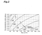
- Fig. 2 is a graph showing a relationship at a wavelength of 1550 nm between transmission loss, effective area and OSNR of optical fibers;
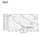
- Fig. 3 is a graph showing a relationship at the wavelength of 1550 nm between transmission loss, effective area and power of pumping light for Raman amplification of optical fibers;
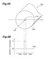
- Fig. 4A shows a cross-sectional structure of an optical fiber according to a first example that can be applied to the optical communications system according to the present embodiment, and Fig. 4B shoes a refractive index profile thereof;
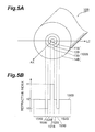
- Fig. 5A shows a cross-sectional structure of an optical fiber (second configuration) according to a second example that can be applied to an optical communications system according to the present embodiment, and Fig. 5B shows a refractive index profile thereof;
- Fig. 6 is a cross-sectional view showing a third configuration of an optical fiber according to the second example.
- Fig. 1 is a view showing the configuration of an optical communications system 1 according to the present embodiment.
- the optical communications system 1 comprises a transmitter station, one or more repeater stations, a receiver station, and an optical fiber 10 serving as a transmission medium, namely an optical fiber laid in the transmission section that is positioned between the transmitter station (or repeater station) and the receiver station (or repeater station).
- one end 10a of the optical fiber 10 is optically connected to the transmitter station (or repeater station) 20, while the other end 10b is optically connected to the receiver station (or repeater station) 30.
- the optical fiber 10 is laid in the transmission section between the transmitter station (or repeater station) 20 and the receiver station (or repeater station) 30.
- the optical signals are transmitted from the transmitter station (or repeater stations) 20 to the receiver station (or repeater stations) 30 via the optical fiber 10.
- pumping light for Raman amplification outputted by a pumping light source 31 provided in the receiver station (or repeater station) 30, is supplied to the optical fiber 10 via an optical coupler 32.
- the optical signals are distributed-Raman-amplified in the optical fiber 10.
- the optical communications system 1 includes a structure wherein optical signals are transmitted in accordance with a multilevel modulation scheme of four or more levels.
- the transmitter station 20 transmits optical signals to the optical fiber 10 with a multilevel modulation scheme such as QPSK and 16-QAM.
- an optical fiber having various characteristics is ordinarily used as the optical fiber 10 that is laid in the transmission section.
- a dispersion-shifted optical fiber which has, at the wavelength of 1550 nm, a transmission loss of 0.20 dB/km and an effective area of 50 ⁇ m 2
- a single mode optical fiber which has, at the wavelength of 1550 nm, a transmission loss of 0.19 dB/km and an effective area of 80 ⁇ m 2
- a pure silica central core optical fiber which has, at the wavelength of 1550 nm, a transmission loss of 0.16 dB/km and an effective area of 110 ⁇ m 2
- the above-described dispersion-shifted optical fiber will be used in Comparative example A, the above-described single mode optical fiber in Comparative example B, and the above-described pure silica central core optical fiber in Comparative example C.
- Fig. 2 is a graph showing the relationship at the wavelength of 1550 nm between transmission loss, effective area and OSNR of optical fibers.
- the graph shows contour lines of the distribution of the OSNR improvement amount on a plane defined by setting, at the wavelength of 1550 nm, the transmission loss (dB/km) to the ordinate and the effective area A eff ( ⁇ m 2 ) to the abscissa.
- the OSNR improvement amount denotes the improvement amount of OSNR, based on the transmission loss reduction and the phase shift reduction of self-phase modulation in a transmission section 80 km long, while taking as a reference the OSNR of the optical fiber according to Comparative example A.
- Fig. 3 is a graph showing the relationship at the wavelength of 1550 nm between transmission loss, effective area and power of pumping light for Raman amplification of optical fibers.
- the graph shows, by using contour lines, the power distribution of the pumping light for Raman amplification on a plane defined by setting, at the wavelength of 1550 nm, the transmission loss (dB/km) to the ordinate and the effective area A eff ( ⁇ m 2 ) to the abscissa.
- the power of the pumping light for Raman amplification denotes the power of the pumping light at a wavelength of 1450 nm as required for obtaining a Raman amplification gain that just balances out the transmission loss at the wavelength of 1550 nm, in a transmission section 80 km long.
- Figs. 2 and 3 the positions of the optical fibers according to Comparative examples A to C are shown, and the range of the optical fiber 10 that is used in the optical communications system 1 according to the present embodiment is also indicated.
- the transmission loss ⁇ (dB/km) and the effective area A eff ( ⁇ m 2 ) of the optical fiber 10 according to the present embodiment satisfy, at the wavelength of 1550 nm, the following relationships (2a) to (2c): ⁇ ⁇ - 0.001 ⁇ A eff + 0.27 0.13 ⁇ ⁇ ⁇ 0.15 A eff ⁇ 120
- the OSNR can be improved (see Fig. 2 ) while suppressing the power increase of the pumping light for distributed Raman amplification (see Fig. 3 ), as compared with cases in which the optical fibers of Comparative example A to C are used. Examples of such an optical fiber 10 are explained next.
- Figs. 4A and 4B show the cross-sectional structure of an optical fiber according to a first example that can be used in the optical communications system according to the present embodiment, and the refractive index profile thereof.
- the optical fiber 10A of the first example comprises a central core 11A which has a refractive index n 1 and extends along a predetermined axis (optical axis AX), and a cladding 100A which has a refractive index n 2 ( ⁇ n 1 ) and surrounds the outer periphery of the central core 11A.
- FIG. 4B is a refractive index profile 150A of the optical fiber 10A, along the line L1 (line orthogonal to the optical axis AX) in Fig. 4A .
- a region 151A denotes a refractive index of the central core 11A along the line L1
- a region 152A denotes the refractive index of cladding 110A along the line L1.
- the optical fiber 10A of the first example comprises, for instance, the central core 11A, and the cladding 100A which surrounds the outer periphery of the central core 11 A and which has a refractive index n 2 lower than the refractive index n 1 of the central core 11A, and has, at the wavelength of 1550 nm, a transmission loss of 0.15 dB/km and an effective area of 120 ⁇ m 2 .
- the relative refractive index difference of the central core 11A with respect to the cladding 100A is 0.26%, and the diameter of the central core 11A is 10.8 ⁇ m.
- the fictive temperature of the central core 11A is 1300°C. The fictive temperature can be realized by controlling the cooling rate during drawing and promoting the relaxation of the glass structure of the central core 11A.
- the OSNR improvement amounts of the optical fiber disclosed in Document 1 (average loss: 0.169 dB/km, effective area: 90 ⁇ m 2 based on the disclosure of Document 2) and of the optical fiber disclosed in Document 3 (loss: 0.184 dB/km, effective area: 120 ⁇ m 2 ) are just under 5 dB.
- the OSNR improvement amount in the optical fiber of the first example is of about 7 dB, i.e. an OSNR improvement amount of 2 dB or more can be realized.
- the OSNR at the wavelength of 1550 nm in a receiver terminal in multi-stage optical amplification/repeating systems is expressed by equation (3) below.
- the OSNR improvement of 2 dB allows elongating the transmission distance about 1.6-fold.
- P in denotes the optical power per wavelength channel to be inputted into the optical fiber
- NF denotes the noise figure of the optical amplifier
- L sp denotes the loss of the transmission section
- OSNR 58 + P in - NF - L sp - 10 ⁇ logN amp
- System performance in optical communications systems based on optical amplification/repeating can be improved by using distributed Raman amplification.
- the power of the pumping light for Raman amplification of the optical fiber (loss: 0.184 dB/km, effective area: 120 ⁇ m 2 ) disclosed in Document 3 must be about 1.5 times that of a standard single mode optical fiber (optical fiber of Comparative example B).
- the power of the pumping light for Raman amplification of the optical fiber 10A of the first example can be about the same as that of the optical fiber of Comparative example B.
- a first configuration of an optical fiber of a second example comprises a central core having a cross-sectional structure and a refractive index profile identical to those of the optical fiber 10A of the above-described first example (see Figs. 4A and 4B ), and a cladding surrounding the central core and having a lower refractive index than that of the central core.
- the optical fiber of the second example has, at the wavelength of 1550 nm, a transmission loss of 0.13 dB/km and an effective area of 140 ⁇ m 2 .
- the central core (first configuration) of the optical fiber of the second example is preferably comprised of pure silica glass, or silica glass obtained by doping pure silica glass with at least one of P 2 O 5 of 1 mol% or more but 10 mol% or less, Cl of less than 2000 mol ppm, F of 2000 mol ppm or more but 10000 mol ppm or less, and A 2 O (where A is an alkali metal element) of 1 mol ppm or more but 10000 mol ppm or less.
- the pure silica glass contains Cl of 2000 mol ppm or more but 20000 mol ppm or less that is incorporated in the dehydration process during a fiber fabrication.
- Suitable alkali metal elements in the A 2 O are Na, K, Rb and Cs.
- a second configuration of the optical fiber of the second example has, for instance, a cross-sectional structure and a refractive index profile such as those shown in Figs. 5A and 5B .
- an optical fiber 10B (second configuration) of the second example has a central core 11B extending along a predetermined axis (optical axis AX) and having a refractive index n 1 , and a cladding 100B which surrounds the outer periphery of the central core 11B, as shown in Fig. 5A .
- the cladding 100B comprises a first cladding 12B which surrounds the outer periphery of the central core 11B and has a refractive index n 2 ( ⁇ n 1 ), a second cladding 13B which surrounds the outer periphery of the first cladding 12B and has a refractive index n 3 ( ⁇ n 2 ), and a third cladding 14B which surrounds the outer periphery of the second cladding 13B and has a refractive index n 2 (> n 3 ).
- Fig. 5B is a refractive index profile 150B of the optical fiber 10B, along line the L2 (line orthogonal to the optical axis AX) in Fig. 5A .
- a region 151B denotes the refractive index of the central core 11B along the line L2
- region 152B denotes the refractive index of the first cladding 12B along the line L2
- region 153B denotes the refractive index of the second cladding 13B along line the L2
- region 154B denotes the refractive index of the third cladding 14B along the line L2.
- the refractive index n 1 of the central core 11B is highest, and the refractive index n 3 of the second cladding 13B is lowest, from among the refractive indices of the regions in the optical fiber 10B.
- the first to third claddings 12B to 14B are doped with F element.
- the second cladding 13B is comprised of silica glass doped with F element whose amount is more than the doping amount of F element in each of the first cladding 12B and the third cladding 14B.
- the second cladding 13B is suitably comprised of silica glass having formed therein a plurality of voids extending in the fiber axial direction (optical axis AX) (see optical fiber 10C of a third configuration, shown in Fig. 6 ).
- the diameter of the central core 11B is 11.9 ⁇ m.
- the diameter of the first cladding 12B is 20.8 ⁇ m.
- the diameter of the second cladding 13B is 39.0 ⁇ m.
- the diameter of the third cladding 14B is 125 ⁇ m.
- Fig. 6 is a cross-sectional view showing the third configuration of the optical fiber of the second example.
- the third configuration differs from the above-described second configuration in that now the second cladding is comprised of silica glass having formed therein a plurality of voids extending in the fiber axial direction (optical axis AX).
- the optical fiber 10C of the third configuration comprises a central core 11C extending along a predetermined axis (optical axis AX) and having a refractive index n 1 , and a cladding 100C which surrounds the outer periphery of the central core 11C.
- the cladding 100C comprises a first cladding 12C which surrounds the outer periphery of the central core 11C and has a refractive index n 2 ( ⁇ n 1 ), a second cladding 13C which surrounds the outer periphery of the first cladding 12C and has a refractive index n 3 ( ⁇ n 2 ), and a third cladding 14C which surrounds the outer periphery of the second cladding 13C and has a refractive index n 2 (> n 3 ).
- the lowest refractive index (n 3 ) is realized in the second cladding 13C, from among the regions that make up the optical fiber 10C, thanks to the plurality of voids 120 formed along the optical axis AX (the optical fiber 10C has the same refractive index profile as the refractive index profile 150B shown in Fig. 5B ).
- a transmission loss of 0.13 dB/km can be realized in the optical fiber of the second example (first to third configurations) through lowering of the viscosity of the silica glass and by setting of the fictive temperature of the central core, in the fiber state, to about 1000 degrees.
- a fictive temperature of 1000 degrees in the central core can be realized by forming the central core from pure silica glass, or silica glass obtained by doping pure silica glass with at least one of P 2 O 5 of 1 mol% or more but 10 mol% or less, Cl of less than 2000 mol ppm, F of 2000 mol ppm or more but 10000 mol ppm or less, and A 2 O (where A is an alkali metal element) of 1 mol ppm or more but 10000 mol ppm or less.
- Pure silica glass contains Cl of 2000 mol ppm to 20000 mol ppm that is incorporated in the dehydration process during a fiber fabrication.
- Suitable alkali metal elements in the A 2 O are Na, K, Rb and Cs.
- a fictive temperature of 1000 degrees in the central core can be realized by manufacturing an optical fiber having a central core of pure silica glass, P 2 O 5 -doped silica glass or the above-described alkali-metal-doped silica glass, while controlling the cooling rate during drawing.
- macrobending can be kept down at a level similar to that of standard single mode optical fibers by, for instance, providing the low-refractive index second claddings 13B, 13C, such as those shown in Figs. 5A and 6 .
- Microbending can be kept down at a level similar to that of standard single mode optical fibers by, for instance, improving fiber sheathing.
- the OSNR improvement amount of the optical fiber of the second example is about 9 dB, which constitutes an improvement of 4 dB or more over the optical fibers disclosed in Documents 1 and 3.
- an OSNR improvement of 4 dB enables a transition from QPSK to 16-QAM while keeping the error rate constant. Therefore, the optical communications system 1 according to the present embodiment, in which an optical fiber of the second example is laid in a transmission section, allows realizing a transmission capacity that is double that of the optical communications systems disclosed in Documents 1 and 3.
- the power of the pumping light for Raman amplification can be kept equivalent to or lower than that of a standard single mode optical fiber.
- optical communications system allows improving OSNR while curbing increases in the power of the pumping light for distributed Raman amplification.
Landscapes
- Physics & Mathematics (AREA)
- General Physics & Mathematics (AREA)
- Optics & Photonics (AREA)
- Electromagnetism (AREA)
- Engineering & Computer Science (AREA)
- Computer Networks & Wireless Communication (AREA)
- Signal Processing (AREA)
- Optical Modulation, Optical Deflection, Nonlinear Optics, Optical Demodulation, Optical Logic Elements (AREA)
- Optical Communication System (AREA)
Applications Claiming Priority (1)
| Application Number | Priority Date | Filing Date | Title |
|---|---|---|---|
| JP2009183666A JP2011039109A (ja) | 2009-08-06 | 2009-08-06 | 光通信システム |
Publications (2)
| Publication Number | Publication Date |
|---|---|
| EP2284584A2 true EP2284584A2 (de) | 2011-02-16 |
| EP2284584A3 EP2284584A3 (de) | 2014-05-07 |
Family
ID=43127462
Family Applications (1)
| Application Number | Title | Priority Date | Filing Date |
|---|---|---|---|
| EP10172149.6A Withdrawn EP2284584A3 (de) | 2009-08-06 | 2010-08-06 | Optisches Kommunikationssystem |
Country Status (4)
| Country | Link |
|---|---|
| US (2) | US8145024B2 (de) |
| EP (1) | EP2284584A3 (de) |
| JP (1) | JP2011039109A (de) |
| CN (1) | CN101997609A (de) |
Families Citing this family (4)
| Publication number | Priority date | Publication date | Assignee | Title |
|---|---|---|---|---|
| JP2011039109A (ja) * | 2009-08-06 | 2011-02-24 | Sumitomo Electric Ind Ltd | 光通信システム |
| JP6459215B2 (ja) * | 2014-05-14 | 2019-01-30 | 住友電気工業株式会社 | 光ファイバ及び光ファイバの評価方法 |
| EP3156830B1 (de) | 2014-06-13 | 2020-12-30 | Sumitomo Electric Industries, Ltd. | Optisches übertragungssystem |
| CN113009619B (zh) * | 2015-04-15 | 2024-01-16 | 康宁股份有限公司 | 具有氟和氯共掺杂芯区域的低损耗光纤 |
Family Cites Families (24)
| Publication number | Priority date | Publication date | Assignee | Title |
|---|---|---|---|---|
| WO2000042458A1 (en) * | 1999-01-18 | 2000-07-20 | Sumitomo Electric Industries, Ltd. | Optical fiber and method of manufacture thereof |
| EP1107027B1 (de) * | 1999-04-13 | 2011-10-12 | Sumitomo Electric Industries, Ltd. | Optischer faser und optischer übertragungssystem mit eine solche optische faser |
| JP2001255564A (ja) * | 2000-03-09 | 2001-09-21 | Nippon Telegr & Teleph Corp <Ntt> | ラマン増幅用ファイバおよび光ファイバ線路 |
| JP2002072263A (ja) * | 2000-08-25 | 2002-03-12 | Sumitomo Electric Ind Ltd | 光ファイバ伝送路および光伝送システム |
| US6879759B2 (en) * | 2001-01-08 | 2005-04-12 | Alcatel | Apparatus and method for on-line binder laylength measurement and adjustment |
| JP2002299738A (ja) * | 2001-03-29 | 2002-10-11 | Toshiba Corp | 光伝送システム |
| JP2003066261A (ja) * | 2001-08-27 | 2003-03-05 | Sumitomo Electric Ind Ltd | 光伝送路および光通信システム |
| US6856744B2 (en) * | 2002-02-13 | 2005-02-15 | The Furukawa Electric Co., Ltd. | Optical fiber and optical transmission line and optical communication system including such optical fiber |
| JP4244925B2 (ja) * | 2002-07-10 | 2009-03-25 | 住友電気工業株式会社 | 光ファイバの製造方法 |
| JP2004238275A (ja) * | 2002-12-12 | 2004-08-26 | Toyota Gakuen | 光ファイバ及びその製造方法 |
| KR100506311B1 (ko) * | 2003-01-20 | 2005-08-05 | 삼성전자주식회사 | 광대역 분산 제어 광섬유 |
| US6904218B2 (en) * | 2003-05-12 | 2005-06-07 | Fitel U.S.A. Corporation | Super-large-effective-area (SLA) optical fiber and communication system incorporating the same |
| KR100584951B1 (ko) * | 2003-07-23 | 2006-05-29 | 엘에스전선 주식회사 | 고속, 대용량의 파장분할다중화 시스템에 적합한 광섬유,이를 이용한 광전송선 및 광통신 시스템 |
| JP3952039B2 (ja) * | 2004-05-24 | 2007-08-01 | 日本電気株式会社 | 測定装置、光伝送システム、及びラマン利得測定方法 |
| FR2871899B1 (fr) * | 2004-06-22 | 2006-09-15 | Alcatel Sa | Fibre optique a compensation de dispersion chromatique |
| KR100602755B1 (ko) * | 2004-07-08 | 2006-07-20 | 엘에스전선 주식회사 | 영분산 파장이 단파장대로 이동된 광섬유, 이를 이용한광전송선 및 광통신 시스템 |
| US20070003198A1 (en) * | 2005-06-29 | 2007-01-04 | Lance Gibson | Low loss optical fiber designs and methods for their manufacture |
| JPWO2007034923A1 (ja) * | 2005-09-23 | 2009-04-02 | 古河電気工業株式会社 | 光ファイバ |
| JP2008009036A (ja) * | 2006-06-28 | 2008-01-17 | Osaka Prefecture Univ | 単一モード光ファイバ伝送路の実効ラマン利得係数の評価方法及び評価装置 |
| JP4679455B2 (ja) * | 2006-07-13 | 2011-04-27 | 富士通株式会社 | 光増幅方法、光増幅器および光伝送システム |
| JP4999063B2 (ja) * | 2006-10-19 | 2012-08-15 | 古河電気工業株式会社 | 光ファイバ |
| FR2914751B1 (fr) * | 2007-04-06 | 2009-07-03 | Draka Comteq France | Fibre optique monomode |
| US7844155B2 (en) * | 2007-05-07 | 2010-11-30 | Corning Incorporated | Optical fiber containing alkali metal oxide |
| JP2011039109A (ja) * | 2009-08-06 | 2011-02-24 | Sumitomo Electric Ind Ltd | 光通信システム |
-
2009
- 2009-08-06 JP JP2009183666A patent/JP2011039109A/ja active Pending
-
2010
- 2010-08-05 US US12/850,669 patent/US8145024B2/en active Active
- 2010-08-06 CN CN201010250351XA patent/CN101997609A/zh active Pending
- 2010-08-06 EP EP10172149.6A patent/EP2284584A3/de not_active Withdrawn
-
2012
- 2012-02-13 US US13/371,835 patent/US8346041B2/en active Active
Non-Patent Citations (3)
| Title |
|---|
| G CHARLET ET AL., ECOC, 2008 |
| JIANJUN YU ET AL., ECOC, 2008 |
| K. NAGAYAMA ET AL., ELECTRONICS LETTERS, vol. 38, no. 20, 2002 |
Also Published As
| Publication number | Publication date |
|---|---|
| US20120148258A1 (en) | 2012-06-14 |
| CN101997609A (zh) | 2011-03-30 |
| US8145024B2 (en) | 2012-03-27 |
| EP2284584A3 (de) | 2014-05-07 |
| US20110044700A1 (en) | 2011-02-24 |
| US8346041B2 (en) | 2013-01-01 |
| JP2011039109A (ja) | 2011-02-24 |
Similar Documents
| Publication | Publication Date | Title |
|---|---|---|
| EP2362252B1 (de) | Glasfaser und optisches Kommunikationssystem damit | |
| CA2422088C (en) | Network for distributing signals to a plurality of user equipment | |
| US6879764B2 (en) | Dispersion shifted fiber having low dispersion slope | |
| EP2894498B1 (de) | Optische faser | |
| US6477306B2 (en) | Dispersion-compensating optical fiber, and, optical transmission line and dispersion-compensating module respectively including the same | |
| US6400877B1 (en) | Negative-dispersion optical fiber and optical transmission line incorporating the same | |
| US20090123122A1 (en) | Optical fibers and optical transmission systems | |
| EP1116969A1 (de) | Dispersionskompensierte glasfaser und optische übertragungsstrecke | |
| KR20020038785A (ko) | 분산 및 분산 기울기가 보상된 섬유 링크 | |
| US7426327B2 (en) | Low attenuation non-zero dispersion shifted optical fiber | |
| NZ512543A (en) | Optical system and method having low loss and non- linear effects | |
| US6633715B2 (en) | Optical fiber having negative dispersion, negative dispersion slope and large effective area | |
| EP1396743A2 (de) | Dispersionskompensierende optische Faser | |
| CN102193140B (zh) | 光纤及包含光纤的光通信系统 | |
| US8346041B2 (en) | Optical communications system | |
| US7164829B2 (en) | Optical fiber, optical transmission line and optical communications system | |
| KR100749295B1 (ko) | 분산 보상 광 화이버, 광 전송로 및 분산 보상 모듈 | |
| EP2000832A9 (de) | Optisches kommunikationssystem | |
| US7978949B2 (en) | Optical fibers and optical transmission systems | |
| WO2007005332A2 (en) | Non-zero dispersion shifted optical fiber | |
| EP1291688A2 (de) | Optische Übertragungsleitung und optisches Übertragungssystem | |
| RU2356077C2 (ru) | Оптическое волокно и система связи, и система мультиплексирования с разделением по длине волны | |
| Hasegawa et al. | Advances in ultra-low loss silica fibers | |
| US6898361B2 (en) | Dispersion-compensating optical fiber and optical transmission line | |
| CN100501466C (zh) | 单模光传输光纤 |
Legal Events
| Date | Code | Title | Description |
|---|---|---|---|
| PUAI | Public reference made under article 153(3) epc to a published international application that has entered the european phase |
Free format text: ORIGINAL CODE: 0009012 |
|
| AK | Designated contracting states |
Kind code of ref document: A2 Designated state(s): AL AT BE BG CH CY CZ DE DK EE ES FI FR GB GR HR HU IE IS IT LI LT LU LV MC MK MT NL NO PL PT RO SE SI SK SM TR |
|
| AX | Request for extension of the european patent |
Extension state: BA ME RS |
|
| PUAL | Search report despatched |
Free format text: ORIGINAL CODE: 0009013 |
|
| AK | Designated contracting states |
Kind code of ref document: A3 Designated state(s): AL AT BE BG CH CY CZ DE DK EE ES FI FR GB GR HR HU IE IS IT LI LT LU LV MC MK MT NL NO PL PT RO SE SI SK SM TR |
|
| AX | Request for extension of the european patent |
Extension state: BA ME RS |
|
| RIC1 | Information provided on ipc code assigned before grant |
Ipc: G02B 6/02 20060101ALI20140328BHEP Ipc: G02B 6/036 20060101AFI20140328BHEP Ipc: H04B 10/291 20130101ALI20140328BHEP |
|
| STAA | Information on the status of an ep patent application or granted ep patent |
Free format text: STATUS: THE APPLICATION HAS BEEN WITHDRAWN |
|
| 18W | Application withdrawn |
Effective date: 20140505 |