EP2284565A1 - Dauerstrichradar - Google Patents
Dauerstrichradar Download PDFInfo
- Publication number
- EP2284565A1 EP2284565A1 EP10251352A EP10251352A EP2284565A1 EP 2284565 A1 EP2284565 A1 EP 2284565A1 EP 10251352 A EP10251352 A EP 10251352A EP 10251352 A EP10251352 A EP 10251352A EP 2284565 A1 EP2284565 A1 EP 2284565A1
- Authority
- EP
- European Patent Office
- Prior art keywords
- frequency
- signal
- transmitted
- beat signal
- continuous wave
- Prior art date
- Legal status (The legal status is an assumption and is not a legal conclusion. Google has not performed a legal analysis and makes no representation as to the accuracy of the status listed.)
- Withdrawn
Links
- 230000005540 biological transmission Effects 0.000 claims abstract description 13
- 238000005070 sampling Methods 0.000 claims abstract description 8
- 230000001131 transforming effect Effects 0.000 claims abstract description 7
- 230000003111 delayed effect Effects 0.000 claims abstract description 6
- 238000000034 method Methods 0.000 claims description 8
- 238000001228 spectrum Methods 0.000 description 8
- 230000035559 beat frequency Effects 0.000 description 6
- 230000008901 benefit Effects 0.000 description 4
- 230000008569 process Effects 0.000 description 4
- 230000008859 change Effects 0.000 description 3
- 238000010586 diagram Methods 0.000 description 3
- 238000012886 linear function Methods 0.000 description 2
- 239000007787 solid Substances 0.000 description 2
- 238000012935 Averaging Methods 0.000 description 1
- 238000013459 approach Methods 0.000 description 1
- 230000006399 behavior Effects 0.000 description 1
- 230000000295 complement effect Effects 0.000 description 1
- 230000008878 coupling Effects 0.000 description 1
- 238000010168 coupling process Methods 0.000 description 1
- 238000005859 coupling reaction Methods 0.000 description 1
- 230000007423 decrease Effects 0.000 description 1
- 238000001514 detection method Methods 0.000 description 1
- 230000000694 effects Effects 0.000 description 1
- 238000001914 filtration Methods 0.000 description 1
- 230000006870 function Effects 0.000 description 1
- 230000010363 phase shift Effects 0.000 description 1
- 230000004044 response Effects 0.000 description 1
- 238000009420 retrofitting Methods 0.000 description 1
- 230000003595 spectral effect Effects 0.000 description 1
Images


Classifications
-
- G—PHYSICS
- G01—MEASURING; TESTING
- G01S—RADIO DIRECTION-FINDING; RADIO NAVIGATION; DETERMINING DISTANCE OR VELOCITY BY USE OF RADIO WAVES; LOCATING OR PRESENCE-DETECTING BY USE OF THE REFLECTION OR RERADIATION OF RADIO WAVES; ANALOGOUS ARRANGEMENTS USING OTHER WAVES
- G01S13/00—Systems using the reflection or reradiation of radio waves, e.g. radar systems; Analogous systems using reflection or reradiation of waves whose nature or wavelength is irrelevant or unspecified
- G01S13/02—Systems using reflection of radio waves, e.g. primary radar systems; Analogous systems
- G01S13/06—Systems determining position data of a target
- G01S13/08—Systems for measuring distance only
- G01S13/32—Systems for measuring distance only using transmission of continuous waves, whether amplitude-, frequency-, or phase-modulated, or unmodulated
- G01S13/34—Systems for measuring distance only using transmission of continuous waves, whether amplitude-, frequency-, or phase-modulated, or unmodulated using transmission of continuous, frequency-modulated waves while heterodyning the received signal, or a signal derived therefrom, with a locally-generated signal related to the contemporaneously transmitted signal
- G01S13/347—Systems for measuring distance only using transmission of continuous waves, whether amplitude-, frequency-, or phase-modulated, or unmodulated using transmission of continuous, frequency-modulated waves while heterodyning the received signal, or a signal derived therefrom, with a locally-generated signal related to the contemporaneously transmitted signal using more than one modulation frequency
-
- G—PHYSICS
- G01—MEASURING; TESTING
- G01S—RADIO DIRECTION-FINDING; RADIO NAVIGATION; DETERMINING DISTANCE OR VELOCITY BY USE OF RADIO WAVES; LOCATING OR PRESENCE-DETECTING BY USE OF THE REFLECTION OR RERADIATION OF RADIO WAVES; ANALOGOUS ARRANGEMENTS USING OTHER WAVES
- G01S13/00—Systems using the reflection or reradiation of radio waves, e.g. radar systems; Analogous systems using reflection or reradiation of waves whose nature or wavelength is irrelevant or unspecified
- G01S13/02—Systems using reflection of radio waves, e.g. primary radar systems; Analogous systems
- G01S13/06—Systems determining position data of a target
- G01S13/08—Systems for measuring distance only
- G01S13/32—Systems for measuring distance only using transmission of continuous waves, whether amplitude-, frequency-, or phase-modulated, or unmodulated
- G01S13/34—Systems for measuring distance only using transmission of continuous waves, whether amplitude-, frequency-, or phase-modulated, or unmodulated using transmission of continuous, frequency-modulated waves while heterodyning the received signal, or a signal derived therefrom, with a locally-generated signal related to the contemporaneously transmitted signal
- G01S13/346—Systems for measuring distance only using transmission of continuous waves, whether amplitude-, frequency-, or phase-modulated, or unmodulated using transmission of continuous, frequency-modulated waves while heterodyning the received signal, or a signal derived therefrom, with a locally-generated signal related to the contemporaneously transmitted signal using noise modulation
-
- G—PHYSICS
- G01—MEASURING; TESTING
- G01S—RADIO DIRECTION-FINDING; RADIO NAVIGATION; DETERMINING DISTANCE OR VELOCITY BY USE OF RADIO WAVES; LOCATING OR PRESENCE-DETECTING BY USE OF THE REFLECTION OR RERADIATION OF RADIO WAVES; ANALOGOUS ARRANGEMENTS USING OTHER WAVES
- G01S7/00—Details of systems according to groups G01S13/00, G01S15/00, G01S17/00
- G01S7/02—Details of systems according to groups G01S13/00, G01S15/00, G01S17/00 of systems according to group G01S13/00
- G01S7/35—Details of non-pulse systems
-
- G—PHYSICS
- G01—MEASURING; TESTING
- G01S—RADIO DIRECTION-FINDING; RADIO NAVIGATION; DETERMINING DISTANCE OR VELOCITY BY USE OF RADIO WAVES; LOCATING OR PRESENCE-DETECTING BY USE OF THE REFLECTION OR RERADIATION OF RADIO WAVES; ANALOGOUS ARRANGEMENTS USING OTHER WAVES
- G01S13/00—Systems using the reflection or reradiation of radio waves, e.g. radar systems; Analogous systems using reflection or reradiation of waves whose nature or wavelength is irrelevant or unspecified
- G01S13/02—Systems using reflection of radio waves, e.g. primary radar systems; Analogous systems
- G01S2013/0236—Special technical features
- G01S2013/0281—LPI, Low Probability of Intercept radar
Definitions
- This invention relates to continuous wave radar apparatus and methods, and it is particularly, although not exclusively, useful for radar systems in which it is necessary to detect targets only over a limited range swath.
- One application of the invention is in the terminal guidance of seekers, since the invention can be used with a very large bandwidth giving it high range resolution.
- FM ranging involves changing the transmitter frequency at a constant rate, so that the frequency against time appears as a series of ramps of equal slope, the length of the slope generally being many times the maximum round trip transit time.
- modulated continuous transmissions are useful for making effective use of solid state transmitters and are hard to intercept.
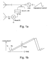
- Figure 1A of the accompanying drawings the transmitted wave form being shown in Figure 1B .
- An additional advantage of conventional FMCW systems is that the signal processing bandwidth can be reduced to a fraction of that normally required in order to provide a given range resolution, by the device of processing signals only up to a desired maximum range.
- the purpose of the present invention is to make a radar that is more difficult to detect whilst minimising the processing rate for radar signals, and maintaining a sufficiently useful bandwidth.
- the invention provides a continuous wave frequency shift-keyed radar apparatus comprising means for changing the frequency of the transmitted continuous wave periodically and in a pseudo-random sequence, means for mixing the received wave with the transmitted wave or a delayed version thereof to produce a beat signal, means for sampling the beat signal, in respect of each period of simultaneous transmission and reception at the same frequency, means for reordering successive segments of the sampled beat signal to put them in sequential frequency order, and means for transforming the reordered segments to provide an output signal in the range domain.
- the invention also provides a continuous wave frequency shift-keyed radar method comprising changing the frequency of a transmitted continuous wave periodically and in a pseudo-random sequence, mixing the received wave with the transmitted wave or a delayed version thereof to produce a beat signal, sampling the beat signal in respect of each period of simultaneous transmission and reception at the same frequency, reordering successive segments of the sampled beat signal to put them in sequential frequency order, and transforming the reordered segments to provide an output signal in the range domain.
- the invention can process these efficiently with an analogue-to-digital converter with a much lower bandwidth than that of the transmitted signal.
- the invention makes the radar signals more difficult to detect than those of other modulated continuous wave systems.
- the radar apparatus of the invention works well only over a limited range swath, which may typically be one kilometre wide, which is limited because of the need for an overlap in time between the segments of transmitted and received signals at the same frequency, to produce a relatively low frequency beat signal which is sampled.
- An advantage of FMCW radars is that a strong return at zero range from direct leakage between the transmitter and the receiver can be eliminated by AC coupling the antenna to the receiver. This is also possible with the present invention.
- the present invention achieves the desirable aim of reduced processing rate for the received signals returned from targets, and the transforming means is preferably an FFT, fast Fourier transform, processor.
- the segments are preferably of equal duration.
- the radar apparatus preferably comprises:
- the mixing means comprises:
- a conventional linear frequency modulated continuous wave, FMCW, radar signal can be processed efficiently using a homodyne receiver, where the received signal is mixed with a copy of the transmitted signal and the difference frequency components, i.e. the beat signal components, are proportional to the power and amplitudes of the returns from different ranges.
- a voltage controlled oscillator, VCO is modulated by a linear ramp voltage signal to produce a frequency swept signal TX as shown in Figure 1B . Most of this signal TX is transmitted, but part of it is used to provide the local oscillator signal to the receiver mixer, usually through a delay line as shown.
- the received signal RX is then mixed with the sample of the transmitted signal to produce a beat frequency F beat .
- the output of the mixer is a beat frequency which is proportional to the time delay between the transmitted and received signals, i.e. to the range to the target.
- the delay line in the path feeding the local oscillator signal to the mixer can be used to minimise the detection of FM noise on any signals leaking directly between the transmitter and the receiver.
- the transmit and receive paths are connected to a common antenna through a circulator, although separate antennas are shown schematically in Figure 1A .
- each target produces its own signal at the mixer output with a frequency proportional to its range.
- the total spectrum of frequencies thus represents the ranges and received powers corresponding to the variety of targets present.
- the spectrum produced in this way is analysed using a fast fourier transform, FFT, processor to provide a series of signals representative of the strength of the reflectors in each range bin.
- FFT fast fourier transform
- the present invention uses more noise-like signals than in FMCW.
- the invention provides a way of doing this using frequency shift-keyed signals, where the signal stays at a fixed frequency for a short period of time, or a "chip”, and then jumps to another, pseudo-randomly chosen, frequency.
- a matched filter is accomplished by multiplying the received spectrum by the complex conjugate of the transmitted spectrum, and the full process can be implemented by
- the homodyne system typically uses a forward FFT to recover the range information from the frequency spectrum. Apart from the irrelevant factors of the absolute amplitudes and the absolute phase in each frequency bin, the difference between the FFT and the inverse FFT can be ignored.
- the difference frequency in this case is equivalent to the multiplication by the complex conjugate, (b).
- An example is a waveform with a chip duration of 10 ⁇ s, and a bandwidth of 10MHz.
- the duration of 10 ⁇ s means that an individual 'chip' will occupy a bandwidth of about 100kHz. It will therefore take about 100 samples to 'fill' the 10MHz spectrum substantially uniformly, so the whole waveform will be transmitted in about a millisecond.
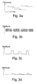
- Each constant-frequency 'chip' is represented by one of the straight lines in the frequency/time graph in figure 2 .
- the solid lines represent the pattern of the transmitted signal and the dotted lines represent the received signal, which is a delayed version of the same pattern.
- the target range is about 800m, i.e. there is a time delay of 5 ⁇ s to and from the target, then using a homodyne receiver, for the second half of each 'chip' the transmitted and received signals will line up. Hence half the energy will be recovered as a low-frequency signal and the rest 'lost' as broad-band noise. For zero range, all the power will be recovered, and at ranges greater or equal to the chip rate nothing will be recovered.
- Figure 3 shows how the concept breaks down as the range increases. As the range increases the overlap between transmitted and received signals decreases and the energy in the low-frequency signal is reduced. Note that if it desired to detect targets over a limited range swathe which does not start at zero, then, if a digitally synthesised signal is used, the local oscillator can be offset in time with respect to the transmitted signal.
- Figure 4 illustrates schematically a radar apparatus embodying the present invention, for processing signals as described above with reference to Figures 2 and 3 .
- the hardware architecture is the same as shown in figure 1 , except that the transmitted signal consists of short sections at fixed frequency followed by a jump to another, randomly-chosen frequency.
- This pattern is illustrated by the solid black lines in the frequency-time plot in Figures 2a and 3a .
- the received frequencies are shown by the dotted line. This is offset in time due to the time of flight to the target and back. This pattern is also shown offset in frequency, for clarity. This might occur in practice due to the Doppler shift from a moving target, but this is not significant to this description.
- Figures 2b and 3b show the output of the homodyne mixer. When the transmit and received frequencies are different a high beat frequency will be produced, but when they are the same a low-frequency signal will be produced. The IF will look like the curves of Figs 2c and 3c , with the high frequency signals having been removed.
- Figures 2d and 3d indicate how the signals appear at the input to the ADC.
- the signal level in Figs 2c and 3c will vary from chip to chip due to the change in phase due to the change in carrier frequency.
- the phase of the beat signal is exp(-2jkr) where r is the range and k is the wave number, 2 ⁇ f/c, where f is the carrier frequency and c is the velocity of propagation (for a radar in the air, the speed of light in air). This is what produces the range resolution information.
- r is the range and k is the wave number, 2 ⁇ f/c, where f is the carrier frequency and c is the velocity of propagation (for a radar in the air, the speed of light in air).
- This produces the range resolution information.
- the digitised samples from each chip are re-arranged in monotonic order of carrier frequency, this variation of amplitude with frequency becomes a sinusoid.
- the re-arranged chips constitute a sum of sinusoids, as in the FMCW case.
- a master clock produces a pulsed signal output which is used for sampling and holding the beat frequency F beat .
- a CODE GENERATOR is clocked by the MASTER CLOCK it outputs a code representing (i) the next frequency to be transmitted and (ii) the next received sample to be sent into an FFT processor.
- the code for the transmitted frequency is passed to a Digital-to-Analogue Converter (DAC) to drive the voltage controlled oscillator (VCO).
- DAC Digital-to-Analogue Converter
- VCO voltage controlled oscillator
- the drive voltage is sketched in the figure and labelled 'Frequency Pattern' to indicate how it differs from the smooth ramp used by the FMCW radar. This generates the transmission signal which is frequency shift-keyed at the frequency of the master clock.
- the code can be generated by the well-known technique of using a shift register with feedback, as explained for example at http://en.wikipedia.org/wiki/Linear_feedback_shift_register:
- the complementary decoding sequence is also generated from a SHIFT REGISTER, in this example.
- the codes could alternatively be read out of a computer memory.
- the only constraint on the code is that all the frequency components must appear once and only once, in the time interval which corresponds to one set of data entering the FFT (which is analogous to the sweep period in the FMCW case).
- the code may repeat again, which can allow better Doppler processing, or may change, which makes its interception somewhat harder.
- the frequency F beat is fed through an analogue-to-digital converter ADC to the shift register.
- the shift register stores digital representations of the amplitude of the beat frequency.
- Sets of adjacent elements of the shift register which store the beat frequency values corresponding to one 'chip' i.e. one transmission at constant frequency, are stored adjacent to other sets of elements for different chip frequencies.
- the contents of the sets of elements in the shift register are accessed in a reordered sequence in monotonically increasing order of the corresponding transmitter frequencies.
- This output from the shift register in sequential order of transmitted frequency is processed in the FFT processor to generate an output signal in the range domain which is then used to generate the usual display of radar targets.
- the shift register following the ADC must be long enough to hold the data from two repetitions of the code.
- the lowest frequency might be 9GHz and each step 100kHz, with a total of 1024 steps to cover a total bandwidth up to just over 9.1GHz.
- the bandwidth might equally be up to 1GHz, but this example gives more typical values.
- This example uses 1024 since an FFT has a number of samples which is a power of 2.
- the reordering of the frequencies can be achieved in many different ways.
- the generation of pseudorandom sequences of numbers, and the decoding of those sequences, is well known and need to be repeated here.
- the frequency steps f 0 + i ⁇ f .
- the transmit frequency f 0 + k ⁇ f
- k ⁇ j is necessary to make the signal pseudo-random.
- the re-ordering of frequencies means taking sample ' j ' at time 'k'; finding which sample was received when frequency f 0 + j ⁇ f was being transmitted, and reading that sample back out at time j .
- the decoding of the pseudorandom sequence of the sets of elements in the shift register is performed by using the output of the CODE GENERATOR.
- the frequency of the beat signal F beat is typically of the order of 100kHz.
- the number of samples taken for each chip may be one or more than one, so that the number of elements of the shift register for each set correspondingly can be one or more than one.
- the signals After reordering the samples in the shift register, the signals represent sine waves oscillating faster the greater the range, as for FMCW.
- a further minor disadvantage is that the waveform will no longer be Doppler-tolerant, because the re-ordering will break up the regular sine waves caused by the Doppler 'beats', unless the Doppler is known and can be compensated for, e.g. for a closing seeker.
- a major advantage is that the zero-range return will come back at DC and so can be removed by high-pass filtering of the signal.
- a further advantage relates to the behaviour with respect to transmitter noise sidebands.
- the received signal In continuous wave radars the received signal must compete with the noise sidebands of the transmitted signal.
- the scheme described restores the relationship by which the weaker signals at longer range are represented by higher frequencies in the receiver and thus compete only with the noise sidebands which are further from the carrier, and are thus weaker because they are further removed from the 1/ f noise components.
- a working example of the invention has been used in a (pseudo-) randomly modulated radar with 10MHz bandwidth but an ADC sampling rate of 100kHz.
- the present invention can be used to modify an existing FMCW radar, e.g. by retrofitting by changing the modulator, modifying the receiver amplifier to give it a flat gain-frequency response, and providing the apparatus, such as shift register and tables, for reordering the samples between the ADC and the FFT.
- the invention can be combined with other well-known architectures for FMCW or pseudo-noise radars, for example the pseudo-random RF signal could also be synthesized digitally, either at the transmitted frequency or at some convenient lower frequency and then converted up to the transmitted frequency using a fixed frequency oscillator.
Landscapes
- Engineering & Computer Science (AREA)
- Radar, Positioning & Navigation (AREA)
- Remote Sensing (AREA)
- Computer Networks & Wireless Communication (AREA)
- Physics & Mathematics (AREA)
- General Physics & Mathematics (AREA)
- Radar Systems Or Details Thereof (AREA)
Applications Claiming Priority (1)
| Application Number | Priority Date | Filing Date | Title |
|---|---|---|---|
| GB0914118A GB2472623A (en) | 2009-08-12 | 2009-08-12 | Continuous wave radar with frequency shift keying |
Publications (1)
| Publication Number | Publication Date |
|---|---|
| EP2284565A1 true EP2284565A1 (de) | 2011-02-16 |
Family
ID=42543388
Family Applications (1)
| Application Number | Title | Priority Date | Filing Date |
|---|---|---|---|
| EP10251352A Withdrawn EP2284565A1 (de) | 2009-08-12 | 2010-07-29 | Dauerstrichradar |
Country Status (3)
| Country | Link |
|---|---|
| US (1) | US20110037642A1 (de) |
| EP (1) | EP2284565A1 (de) |
| GB (1) | GB2472623A (de) |
Families Citing this family (10)
| Publication number | Priority date | Publication date | Assignee | Title |
|---|---|---|---|---|
| US8115672B2 (en) * | 2010-02-02 | 2012-02-14 | Thales | Method of measuring distance, notably for short-range radar |
| KR101336015B1 (ko) * | 2012-06-18 | 2013-12-03 | (주)뮤트로닉스 | 전파고도계 |
| US9645228B1 (en) * | 2012-12-14 | 2017-05-09 | Sandia Corporation | Shaping the spectrum of random-phase radar waveforms |
| JP6376901B2 (ja) * | 2014-08-26 | 2018-08-22 | 株式会社デンソーテン | 受信信号処理装置、レーダ装置、および物標検知方法 |
| US10101438B2 (en) * | 2015-04-15 | 2018-10-16 | Texas Instruments Incorporated | Noise mitigation in radar systems |
| JP2018084450A (ja) * | 2016-11-22 | 2018-05-31 | 三菱電機株式会社 | レーダ装置 |
| US10495728B2 (en) | 2017-03-06 | 2019-12-03 | Honeywell International Inc. | Signal interference prevention system for a frequency-modulated continuous wave radar altimeter |
| DE102017105783B4 (de) * | 2017-03-17 | 2020-06-10 | S.M.S Smart Microwave Sensors Gmbh | Verfahren zum Bestimmen eines Abstandes und einer Geschwindigkeit eines Objektes |
| US11555908B2 (en) * | 2019-09-06 | 2023-01-17 | International Business Machines Corporation | Multi range radar system |
| CN112666917B (zh) * | 2020-11-30 | 2023-10-10 | 河北汉光重工有限责任公司 | 导引头控制系统自动频域辨识及动态特性评价方法 |
Citations (4)
| Publication number | Priority date | Publication date | Assignee | Title |
|---|---|---|---|---|
| US4806935A (en) * | 1987-09-17 | 1989-02-21 | Fosket Timothy G | Closed loop velocity/altitude sensor for FM-CW doppler radars |
| EP0138253B1 (de) | 1983-09-30 | 1991-08-21 | Philips Electronics Uk Limited | Geräuschunterdrückung in mit stetigen Wellen arbeitenden Radaranordnungen |
| US6028548A (en) * | 1997-01-17 | 2000-02-22 | Automotive Systems Laboratory, Inc. | Vehicle collision radar with randomized FSK waveform |
| US20090085796A1 (en) * | 2007-08-08 | 2009-04-02 | Hitachi, Ltd. | Radar Apparatus |
Family Cites Families (2)
| Publication number | Priority date | Publication date | Assignee | Title |
|---|---|---|---|---|
| US3878525A (en) * | 1965-08-03 | 1975-04-15 | Us Navy | Frequency jumping CW radar |
| GB1209025A (en) * | 1966-10-21 | 1970-10-14 | Emi Ltd | Improvements relating to target location systems |
-
2009
- 2009-08-12 GB GB0914118A patent/GB2472623A/en not_active Withdrawn
-
2010
- 2010-07-29 EP EP10251352A patent/EP2284565A1/de not_active Withdrawn
- 2010-08-03 US US12/849,304 patent/US20110037642A1/en not_active Abandoned
Patent Citations (4)
| Publication number | Priority date | Publication date | Assignee | Title |
|---|---|---|---|---|
| EP0138253B1 (de) | 1983-09-30 | 1991-08-21 | Philips Electronics Uk Limited | Geräuschunterdrückung in mit stetigen Wellen arbeitenden Radaranordnungen |
| US4806935A (en) * | 1987-09-17 | 1989-02-21 | Fosket Timothy G | Closed loop velocity/altitude sensor for FM-CW doppler radars |
| US6028548A (en) * | 1997-01-17 | 2000-02-22 | Automotive Systems Laboratory, Inc. | Vehicle collision radar with randomized FSK waveform |
| US20090085796A1 (en) * | 2007-08-08 | 2009-04-02 | Hitachi, Ltd. | Radar Apparatus |
Also Published As
| Publication number | Publication date |
|---|---|
| GB2472623A (en) | 2011-02-16 |
| GB0914118D0 (en) | 2010-07-28 |
| US20110037642A1 (en) | 2011-02-17 |
Similar Documents
| Publication | Publication Date | Title |
|---|---|---|
| EP2284565A1 (de) | Dauerstrichradar | |
| CN111095016B (zh) | 雷达装置 | |
| CN107076834B (zh) | 具有增大的多普勒能力的雷达操作 | |
| EP3373028B1 (de) | Signalinterferenzvermeidungssystem für einen frequenzmodulierten dauerstrichradar-höhenmesser | |
| US9075138B2 (en) | Efficient pulse Doppler radar with no blind ranges, range ambiguities, blind speeds, or Doppler ambiguities | |
| US8031106B2 (en) | Object ranging | |
| EP2006709B1 (de) | Objekterkennung | |
| GB2259820A (en) | A noise radar | |
| WO2020218925A1 (en) | Processing of radar signals for fmcw radar | |
| JP6467974B2 (ja) | 信号発生装置と方法とレーダ装置とプログラム | |
| JP4976439B2 (ja) | レーダ装置 | |
| JP7266207B2 (ja) | レーダ装置、及び、レーダ方法 | |
| CN117826082A (zh) | 一种干扰抑制方法及装置 | |
| JP3799337B2 (ja) | Fm−cwレーダ装置および該装置における妨害波除去方法 | |
| JP2013190217A (ja) | レーダ干渉除去装置及びレーダ干渉除去方法 | |
| KR20200085903A (ko) | 상호 지연된 직교 코드에 의해 개선된 레인지 해상도를 갖는 레이더 시스템의 작동 방법 및 레이더 시스템 | |
| JP4704968B2 (ja) | 相関型探知装置 | |
| JP6629279B2 (ja) | レーダ装置及びそのレーダ信号処理方法 | |
| Lukin et al. | Methods for generation of probing signals in software defined noise radar | |
| KR102020240B1 (ko) | 송신신호 변조를 이용한 fmcw 레이더 다중화 장치 및 그 방법 | |
| CN113906306A (zh) | 信号处理装置和雷达装置 | |
| JP3641551B2 (ja) | 符号相関ドップラレーダ装置 | |
| JP5633848B2 (ja) | 超広帯域パルス・センサ及びその干渉回避方法 | |
| JP3925068B2 (ja) | パルスレーダ装置 | |
| Taniza et al. | High density FPGA based waveform generation for radars |
Legal Events
| Date | Code | Title | Description |
|---|---|---|---|
| PUAI | Public reference made under article 153(3) epc to a published international application that has entered the european phase |
Free format text: ORIGINAL CODE: 0009012 |
|
| AK | Designated contracting states |
Kind code of ref document: A1 Designated state(s): AL AT BE BG CH CY CZ DE DK EE ES FI FR GB GR HR HU IE IS IT LI LT LU LV MC MK MT NL NO PL PT RO SE SI SK SM TR |
|
| AX | Request for extension of the european patent |
Extension state: BA ME RS |
|
| STAA | Information on the status of an ep patent application or granted ep patent |
Free format text: STATUS: THE APPLICATION IS DEEMED TO BE WITHDRAWN |
|
| 18D | Application deemed to be withdrawn |
Effective date: 20110817 |