EP2284472B1 - Target pointing system - Google Patents
Target pointing system Download PDFInfo
- Publication number
- EP2284472B1 EP2284472B1 EP10165903A EP10165903A EP2284472B1 EP 2284472 B1 EP2284472 B1 EP 2284472B1 EP 10165903 A EP10165903 A EP 10165903A EP 10165903 A EP10165903 A EP 10165903A EP 2284472 B1 EP2284472 B1 EP 2284472B1
- Authority
- EP
- European Patent Office
- Prior art keywords
- pointing
- operative condition
- adaptive filter
- displacement
- phasing
- Prior art date
- Legal status (The legal status is an assumption and is not a legal conclusion. Google has not performed a legal analysis and makes no representation as to the accuracy of the status listed.)
- Active
Links
Images



Classifications
-
- F—MECHANICAL ENGINEERING; LIGHTING; HEATING; WEAPONS; BLASTING
- F41—WEAPONS
- F41G—WEAPON SIGHTS; AIMING
- F41G3/00—Aiming or laying means
- F41G3/22—Aiming or laying means for vehicle-borne armament, e.g. on aircraft
-
- F—MECHANICAL ENGINEERING; LIGHTING; HEATING; WEAPONS; BLASTING
- F41—WEAPONS
- F41G—WEAPON SIGHTS; AIMING
- F41G3/00—Aiming or laying means
- F41G3/14—Indirect aiming means
- F41G3/16—Sighting devices adapted for indirect laying of fire
- F41G3/165—Sighting devices adapted for indirect laying of fire using a TV-monitor
Definitions
- the present invention concerns a target pointing system.
- the present invention concerns a pointing system installed onboard a terrestrial vehicle, corresponding, for example, to a tank or similar vehicle, and is configured for conveniently aiding an operator in the operation of aiming at a target, making the tracking operation easier when the vehicle and the target are both in movement.
- the present invention concerns a pointing system of the type comprising an optical pointing device, which in turn is equipped with an optical reflection unit movably mounted on the terrestrial vehicle so that it can move on two orthogonal axes (typically indicated as the "azimuth axis" and the “elevation axis"), an optical sensor (for example, a telecamera) mounted on the vehicle so as to cooperate with the optical unit in order to acquire the images reflected by the latter, a moving device for the optical unit and an automatic optics control system able to pilot the moving device so as to adjust the positions of the optical unit on the azimuth and/or elevation axes during the course of acquiring images.
- an optical reflection unit movably mounted on the terrestrial vehicle so that it can move on two orthogonal axes (typically indicated as the "azimuth axis" and the “elevation axis")
- an optical sensor for example, a telecamera mounted on the vehicle so as to cooperate with the optical unit in order to acquire the images reflected by
- the pointing system also comprises a display able to show the operator/gunner the images acquired by the optical sensor and a graphical pointer, typically represented by crosshairs superimposed on the images, which defines both an "optical pointing reference” regarding the position assumed by the optical unit on the azimuth and elevation axes, and a "firing reference” indicating a quantity correlated to the assumed position of the target and therefore utilizable by an weapon system possibly installed on the terrestrial vehicle for determining the line of fire with which to operate the weapon in order to hit the aimed-at target.
- a display able to show the operator/gunner the images acquired by the optical sensor and a graphical pointer, typically represented by crosshairs superimposed on the images, which defines both an "optical pointing reference” regarding the position assumed by the optical unit on the azimuth and elevation axes, and a "firing reference” indicating a quantity correlated to the assumed position of the target and therefore utilizable by an weapon system possibly installed on the terrestrial vehicle for determining the line of fire with which
- the pointing system also comprises a joystick that can be manually controlled by the operator on two mutually orthogonal control axes, and is configured to provide the automatic control system with control quantities correlated to the displacement of the joystick lever on the two control axes.
- the automatic control system processes the control quantities in order to control the displacement of the optical unit on the azimuth axis and on the elevation axis in response to the displacement of the joystick lever on the first and second control axes respectively.
- the optical unit comprises a mirror that has an optical pointing axis arranged perpendicular to the flat surface of the mirror itself and is movably mounted on the vehicle such that it is possible to move the optical pointing axis on the azimuth axis, and/or on the elevation axis.
- this comprises electric motors connected to the optical mirror via motion transmission members to enable moving of the mirror on the azimuth and elevation axes.
- this comprises an adjustment module, which is configured to stabilize the orientation of the mirror's optical axis, making it independent of the vehicle's angles of orientation measured with respect to the azimuth and elevation axes assumed by the vehicle itself during its movement.
- the adjustment module comprises a gyroscopic device firmly fixed to the tank that receives a precession control angle in input indicating the position to make the precession axis of the gyroscope assume and is able to provide an output signal proportional to the relative angular speed between the gyroscope's precession axis and the mirror's optical pointing axis.
- the adjustment module is configured to cancel the relative angular speed between the precession axis of the gyroscopic device's rotor and the mirror's optical pointing axis by means of a feedback system.
- the optical pointing axis of the mirror therefore tends to assume an angular position that will differ from the precession axis by a constant angle over time, i.e. they will tend to coincide, except for an offset.
- the automatic control system also comprises an electronic controller, which is configured to receive the control quantities generated by the joystick in input, these corresponding to the angular speeds of displacement of the joystick along the two control axes, and to carry out an integration calculation on them in order to generate a command containing the angle that the precession axis of the gyroscopic device's rotor must be made to assume.
- the above-mentioned pointing system is very efficient because the response of the commands issued by the automatic control system to the optical unit based on the speed command generated by joystick, apart from being extremely rapid, exhibits high sensitivity to the manual action exerted by the operator on the joystick lever.
- This difficulty manifests itself as a state of tension for the operator that, as times passes, causes an involuntary increase in imprecision in target pointing.
- the object of the present invention is therefore that of embodying a pointing system that is capable of facilitating the operator in maintaining correct aiming on a mobile target.
- a system is made to facilitate aiming at a target, as provided for in claim 1 and preferably, but not necessarily, in any of the claims directly or indirectly dependent on claim 1.
- a tank is made, as provided for in claim 11.
- reference numeral 1 indicates, in its entirety, a terrestrial vehicle comprising a pointing system 2 configured to facilitate an operator in aiming at a target when the vehicle 1 and/or the target are in movement.
- the terrestrial vehicle 1 is a tank, which comprises a hull 3, extending along a longitudinal axis A and structured to allow the accommodation of operators/gunners, and a weapon system 4, which is mounted on top of the hull 3 and in turn comprises a rotating turret 5, which extends upwards from the hull 2 along an axis B orthogonal to the longitudinal axis A for turning around the same axis B, and a weapon 6, in particular, a cannon positioned on the rotating turret 5.
- the weapon system 4 is of known type and will not be further described, other than specifying that it comprises a moving unit 7 able, upon command, to turn the rotating turret 5 around axis B and/or move the weapon 6 around one or more axes of rotation (not shown), and a weapon control system (not shown) configured to calculate the line of fire to give the weapon 6 and the moment of firing based on a first reference quantity associated with the pointing position established by the pointing system 2, and to pilot the moving unit 7 based on the calculated line of fire.
- this comprises an optical pointing device 8, which in turn is provided with an optical reflection unit 9 movably mounted on the vehicle 1, and an optoelectronic sensor 10, preferably, but not necessarily, comprising a telecamera mounted on the vehicle 1 near to the optical reflection unit 9 so that it acquire the images reflected by the optical reflection unit 9.
- the optical reflection unit 9 comprises a mirror, which has an optical pointing axis C that extends orthogonally from the reflective surface of the mirror and is movably mounted on the turret 5 of the vehicle 1 so as to move the optical pointing axis C along an azimuth axis Ox.
- the azimuth axis Ox lies on a plane that is substantially horizontal and is parallel to the longitudinal axis A and orthogonal to axis B, while the mirror of the optical reflection unit 9 is movably mounted on the vehicle 1 so as to keep the optical pointing axis C on the same horizontal plane.
- the mirror of the optical reflection unit 9 is also movably mounted such that the optical pointing axis C can be moved along an elevation axis Oy, which is substantially orthogonal to the azimuth axis Ox.
- the elevation axis Oy lies on a substantially vertical plane, while the mirror of the optical reflection unit 9 is movably mounted on the vehicle 1 to keep the optical pointing axis C on the same vertical plane.
- the optical pointing device 8 also comprises a moving device 11 for the optical reflection unit 9 and an automatic optics control system 12, which is configured to pilot the moving device 11 in order to adjust the positions of the optical reflection unit 9 along axis Ox and/or axis Oy during pointing.
- the moving device 11 comprises electric motors and/or electromechanical actuators 13 that are connected to the mirror of the optical reflection unit 9 via known systems of motion transmission (not shown) for moving the mirror so as to cause the traverse of the optical pointing axis C along axes Ox and Oy.
- the pointing system 2 also comprises a display 14 located inside the crew compartment built in the hull 2 and able to display the images acquired by the optoelectronic sensor 10 to the operator/gunner.
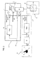
- the display 14 is also able to display a graphical pointer 30 (shown in Figure 2 ) for the operator, preferably, but not necessarily, represented by crosshairs superimposed on the images, which defines both an "optical pointing reference” (i.e. associated with the angular position assumed by the optical pointing axis C with respect to axes Ox and Oy) and the first reference quantity to supply to the weapon system 4 for calculating the line of fire.
- a graphical pointer 30 shown in Figure 2
- crosshairs superimposed on the images, which defines both an "optical pointing reference" (i.e. associated with the angular position assumed by the optical pointing axis C with respect to axes Ox and Oy) and the first reference quantity to supply to the weapon system 4 for calculating the line of fire.
- the pointing system 2 also comprises a manual user control, preferably a joystick 15, which can be manually controlled by the operator in two mutually orthogonal control axes, and is configured to provide the automatic control system 12 with control quantities correlated to the displacement of the joystick lever on the same two control axes.
- a manual user control preferably a joystick 15
- the automatic control system 12 is configured to provide the automatic control system 12 with control quantities correlated to the displacement of the joystick lever on the same two control axes.
- the joystick 15 is equipped with a control lever that can be operated by a user on a first axis X associated with a displacement command of the optical pointing axis C along axis Ox, and a second axis Y orthogonal to axis X and associated with a displacement command of the optical pointing axis C along axis Oy.
- the joystick 15 is configured to generate quantities X(t n ), Y(t n ) indicating the angular position assumed by the control lever of the joystick 15 at nth time t n along the first axis X and/or the second axis Y respectively.
- the automatic control system 12 comprises an adjustment module 16, which is configured to stabilize the orientation of the mirror's optical pointing axis C, rendering it independent of the vehicle's angles of orientation 1 measured with respect to the azimuth and elevation axes assumed by the vehicle 1 itself when in movement.
- the adjustment module 16 comprises a gyroscopic device 18 firmly fixed to the vehicle 1, which receives a precession command ⁇ P in input indicating the angular speed that must be given to the precession axis (not shown) of the gyroscopic device 18 and is able to provide an output signal containing the angular speed ⁇ E existing between the precession axis of the gyroscopic device 18 and the optical pointing axis C of the mirror.
- the adjustment module 16 is of known type and will not be further described, other than specifying that it is configured to cancel the angular speed ⁇ E existing between the precession axis of the rotor (not shown) of the gyroscopic device 18 and the optical pointing axis C of the mirror by means of a feedback control chain 19.
- the saturated angular speeds V s (t n ) (V sx (t n ); V sy (t n ) are associated with the angular displacement of the joystick 15 along axes X and Y and are processed by the electronic controller 21 to define a precession command ⁇ Px , based on which the adjustment module 16 provides for activating, in a known manner, the moving of the mirror along the azimuth axis Ox, and/or a precession command ⁇ Py , based on which the adjustment module 16 provides for activating, in a known manner, the moving of the mirror along the elevation axis Oy.
- the pointing aid module 22 comprises an adaptive filter 23 and is configured to modify the transfer function of the adaptive filter 23 on the basis of the re-phasing or tracking operative condition in course on the pointing system 2.
- the adaptive filter 23 is a digital filter configured to modify the coefficients that characterize the transfer function according to a first or, alternatively, a second filter configuration.
- the adaptive filter 23 assumes a first filter configuration in which the filter's transfer function is a one-pole first order function.
- the adaptive filter 23 assumes a second filter configuration, in which the filter's transfer function is a two-pole second order function.
- the adaptive filter 23 assumes the first filter configuration schematized by block 25 or, alternatively, the second filter configuration schematized by block 26.
- the pointing system 2 provides for controlling the two quantities Ox(t n ) and Oy(t n ) associated with the angular position of the optical pointing axis C along axes Ox and Oy on the basis of the two control quantities X(t n ) and Y(t n ) indicating the position of the joystick lever 15 along axes X and Y at time t n .
- the adaptive filter 23 calculates the angular speeds Vx(t n ) and Vy(t n ) filtered by means of the following functions (block 26):
- Ox t n ⁇ ⁇ x ⁇ X t n
- Oy t n ⁇ ⁇ y ⁇ Y t n
- Ox(t n ) and Oy(t n ) correspond to the angular displacements of the optical pointing axis C at time t n
- Vfx t n Vfx ⁇ t n - 1 + ⁇ ⁇ x / T ⁇ X t n
- Vfy t n Vfy ⁇ t n - 1 + ⁇ ⁇ y / T ⁇ Y t n
- T is the quantity sampling interval
- this is configured to compare the filtered speeds Vx(t n ) and Vy(t n ) with a predetermined maximum angular speed threshold V MAX .
- the compensator module 24 determines a speed saturation condition and assigns the same absolute value of the predetermined maximum angular speed V MAX to the module, at the same time maintaining the sign of the non-saturated quantity.
- the compensator module 24 determines a "non saturation" condition for the speed and assigns the corresponding angular speeds Vx(t n ) and Vy(t n ), obtained in output from the adaptive filter 23, to the speed command Vsx(t n ), V sy (t n ).
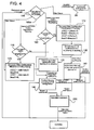
- the pointing aid module 22 assigns a first logical value, equal to 0 for example, to a filter status variable indicated as "Filter Status", whilst in the tracking condition, the pointing aid module 22 assigns a second logical value, equal to 1 for example, to FilterStatus.
- the pointing system can preferably, but not necessarily, envisage that in one of the operative conditions, in the tracking operative condition for example, the position quantities generated by the joystick 15 are processed in the following manner (block 99):
- the pointing aid module 22 receives as input the saturated speed V sx (t n-1 ), hereafter indicated as Omega_p1X, the saturated speed v sy (t n-1 ), hereafter indicated as Omega_p1Y, and the FilterStatus variable and determines whether or not a change in the operative condition is in course on the basis of these parameters.
- variable FilterStatus 1 (exit 100a from block 100)
- the pointing aid module 22 checks if the system was operating in the tracking operative phase at the previous sampling time t n-1 . In this case, the pointing aid module 22 compares the Omega_p1X and Omega_p1Y speeds related to the saturated speeds in the previous tracking operative phase, with a first predetermined speed threshold SogliaAccVel (block 110).
- the pointing aid module 22 confirms the state of preserving the tracking operative phase. In this case, the pointing aid module 22 keeps the second filter configuration of the two-pole filter (block 120) existing at previous time t n-1 unchanged.
- the pointing aid module 22 orders the changeover from the tracking operative condition to the re-phasing operative condition.
- the pointing aid module 22 changes the FilterStatus variable, setting it to 0, sets the first configuration for implementation on the adaptive filter (block 120) and carries out smoothing on the coefficients of the same adaptive filter (block 130).
- Coefficient smoothing provides for gradually modifying the filter's coefficients during the passage from the second to the first configuration of the filter, so that achieving the operating value to assign to each alpha and beta coefficient in the first configuration takes place through a predetermined asymptotic trend with a rise time dependent on the band assigned to the filter itself.
- variable FilterStatus 0 in the initial phase (exit 100b from block 100), then the compensator module 24 determines that the pointing system was in the re-phasing operative condition at previous time t n-1 .
- the pointing aid module 22 compares the absolute value of the speeds Omega_p1X, Omega_p1Y associated with the re-phasing operative phase with a second predetermined speed threshold SogliaVelAcc (block 160).
- the first SogliaAccVel and the second SogliaVelAcc predetermined speed thresholds have different values from each other to guarantee hysteresis in the comparison of the parameters so as to conveniently cancel possible instability conditions in the pointing aid module.
- the pointing aid module 22 decides to keep the previous re-phasing operative phase and keeps the first configuration of the one-pole filter present at previous time t n-1 (block 120) substantially unchanged.
- the pointing aid module 22 operates the changeover from the re-phasing operative phase to the tracking operative phase.
- the pointing aid module 22 provides the compensator module 24 with the speeds OmegaX and OmegaY generated by the adaptive filter 2e using the first configuration (block 140), whilst failing this, namely if the current operative condition corresponds to the tracking operative condition, the pointing aid module 22 provides the compensator module 24 with the speed command OmegaX and OmegaY generated by the adaptive filter 23 using the second configuration.
- the speeds OmegaX and OmegaY are then supplied in input to the compensator module 23, which compares these same speeds OmegaX and OmegaY with the predetermined maximum angular speed threshold V MAX .
- the compensator module 23 then generates the saturated speed V sx (t n ) V sy ( t-n ) on the basis of the above-indicated comparison and supplies it to the electronic controller 16.
- the electronic controller 16 outputs precession command ⁇ P , while the adjustment module 16 pilots the moving device 11 to cause displacement of the mirror of the optical reflection unit 9 as a function of the angle ⁇ Px and angle ⁇ Py .
- the adaptive filter 23 could be defined by a calculation algorithm implemented by a DSP microprocessor and comprising a series of operations described in detail in the following.
- the calculation algorithm provides for the processing of a series of first variables, which are associated with the transition of the pointing system from the re-phasing operative condition to the tracking operative condition and vice versa.
- Second variables are instead associated with quantities regarding the transversal displacement of the optical pointing axis C along axis O x in response to a manual displacement of the control lever of the joystick 15 along axis X.
- Third variables are instead associated with quantities regarding the elevation displacement of the optical pointing axis C along axis O Y in response to a manual displacement of the control lever of the joystick along axis Y.
- the first variables include a variable AlfaVelAcc associated with the temporary alpha coefficient of the filter that can be used in the above-described smoothing phase in the case of transition from the re-phasing condition to the tracking condition.
- the algorithm assigns a constant value of approximately 0.12 to the variable AlfaVelAcc. It should be specified that configuring the adaptive filter 23 with the variable AlfaVelAcc conveniently gives a correlation time Tc for the adaptive filter 23 of approximately 1 second.
- the first variables also include a coefficient AlfaAccVel associated with the temporary alpha coefficient of the adaptive filter 23 that can be used in the above-described smoothing phase in the case of transition from the tracking condition to the re-phasing condition.
- the first variables also include the predetermined speed threshold SogliaVelAcc that, as previously stated, is associated with the transition from the re-phasing condition to the tracking condition.
- the calculation algorithm assigns a value of approximately 10 mrad/sec (0.573 deg/sec) to the variable SogliaVelAcc.
- the first variables also include the predetermined speed threshold SogliaAccVel that, as previously stated, is associated with the transition from the tracking condition to the re-phasing condition.
- the calculation algorithm assigns a value of approximately 14 mrad/sec (0.8 deg/sec) to the variable SogliaAccVel.
- these include the variable AlfaVeloX, containing the value to assign to the alpha parameter of the adaptive filter 23 in conditions of completion of the first configuration associated with the re-phasing operative phase.
- this corresponds to an alpha-beta type filter, in which the coefficients are identified by the second variables AlfaAccX and BetaAccX.
- these include AlfaVeloY, indicating the value to assign to the alpha parameter of the adaptive filter 23 in conditions of completion of the first configuration associated with the re-phasing operative phase.
- the calculation algorithm assigns a value of 1 to variable AlfaVeloY.
- this corresponds to an alpha-beta type filter, in which the coefficients are identified by the third variables AlfaAccY and BetaAccY.
- the pointing aid module 22 also provides for processing the following variables: JoyX and JoyY that (as described above) are associated with the position of the control lever of the joystick 15 along axes X and Y respectively, OmegaX and OmegaY that (as described above) correspond to the filtered transversal speeds along axis X and in elevation along axis Y, and the variable FilterStatus to which the value 0 is assigned in the re-phasing condition and 1 in the tracking condition.
- JoyX and JoyY that (as described above) are associated with the position of the control lever of the joystick 15 along axes X and Y respectively
- OmegaX and OmegaY that (as described above) correspond to the filtered transversal speeds along axis X and in elevation along axis Y
- FilterStatus to which the value 0 is assigned in the re-phasing condition and 1 in the tracking condition.
- the pointing aid module 22 implements a first calculation operation (block 300) on the scaled position commands of the joystick's control lever used in the tracking condition:
- JoyXris JoyX * KjoyX
- JoyYris JoyY * KjoyY
- the pointing aid module 22 selects the operative phase in course.
- the pointing aid module 22 carries out filtering on the positions.
- the compensator module 24 saturates the speed command OmegaX and OmegaY while the pointing aid module 22 controls the saving of the following parameters, which will be used in the next step t n+1 :
- AlfaFilX_p ⁇ 1 AlfafilX
- BetaFilX_p ⁇ 1 BetafilX
- AlfaFilY_p ⁇ 1 AlfafilY
- Omega_p ⁇ 1 ⁇ Y OmegaY block 390 .
- the above-described pointing system is extremely advantageous as it is capable of modifying the filtering band over time as a function of the movement of the joystick produced by the operator.
- the filter when the corrections requested by the pointer operator are substantial, the filter is modified to render pointer movements more rapid. Subsequently, when the operator has positioned the pointer on the target and tends to make small corrections, the calculation algorithm gradually modifies the coefficients that determine the band in order to estimate the speed of the target with good precision. In this condition, the adaptive filter interprets the commands of the joystick lever as acceleration commands and in the case of the target moving at a constant speed, the operator's command will tend to be null.
- the speed command tends to be null, as the pointing system has identified the speed of the target.
- an ideal tracking condition is created in which the sensitivity to disturbances transferred to the joystick lever by the shaking of the vehicle is substantially null.
Landscapes
- Engineering & Computer Science (AREA)
- General Engineering & Computer Science (AREA)
- Aviation & Aerospace Engineering (AREA)
- Control Of Position, Course, Altitude, Or Attitude Of Moving Bodies (AREA)
- Optical Communication System (AREA)
- Position Input By Displaying (AREA)
- Iron Core Of Rotating Electric Machines (AREA)
- Acyclic And Carbocyclic Compounds In Medicinal Compositions (AREA)
Priority Applications (2)
| Application Number | Priority Date | Filing Date | Title |
|---|---|---|---|
| PL10165903T PL2284472T3 (pl) | 2009-06-15 | 2010-06-14 | System wskazywania celu |
| SI201030035T SI2284472T1 (sl) | 2009-06-15 | 2010-06-14 | Sistem za ciljanje |
Applications Claiming Priority (1)
| Application Number | Priority Date | Filing Date | Title |
|---|---|---|---|
| ITTV2009A000130A IT1398694B1 (it) | 2009-06-15 | 2009-06-15 | Sistema di puntamento di un bersaglio |
Publications (2)
| Publication Number | Publication Date |
|---|---|
| EP2284472A1 EP2284472A1 (en) | 2011-02-16 |
| EP2284472B1 true EP2284472B1 (en) | 2012-03-14 |
Family
ID=42167588
Family Applications (1)
| Application Number | Title | Priority Date | Filing Date |
|---|---|---|---|
| EP10165903A Active EP2284472B1 (en) | 2009-06-15 | 2010-06-14 | Target pointing system |
Country Status (6)
| Country | Link |
|---|---|
| EP (1) | EP2284472B1 (pl) |
| AT (1) | ATE549595T1 (pl) |
| ES (1) | ES2384436T3 (pl) |
| IT (1) | IT1398694B1 (pl) |
| PL (1) | PL2284472T3 (pl) |
| SI (1) | SI2284472T1 (pl) |
Families Citing this family (2)
| Publication number | Priority date | Publication date | Assignee | Title |
|---|---|---|---|---|
| RU2551267C1 (ru) * | 2014-02-12 | 2015-05-20 | Евгений Леонидович Белоусов | Система управления вооружением летательных аппаратов |
| CN104111662B (zh) * | 2014-06-10 | 2016-08-24 | 西安应用光学研究所 | 一种光电跟踪仪自动跟踪状态下的单杆补偿方法 |
Family Cites Families (4)
| Publication number | Priority date | Publication date | Assignee | Title |
|---|---|---|---|---|
| SE340061B (pl) * | 1970-03-06 | 1971-11-01 | Bofors Ab | |
| DE2812201C2 (de) * | 1978-03-20 | 1983-02-03 | Licentia Patent-Verwaltungs-Gmbh, 6000 Frankfurt | Vorrichtung zur Ausbildung von Richtschützen für Panzerfahrzeuge |
| US5822713A (en) * | 1993-04-05 | 1998-10-13 | Contraves Usa | Guided fire control system |
| BE1016871A3 (fr) * | 2005-12-05 | 2007-08-07 | Fn Herstal Sa | Dispositif ameliore pour la telecommande d'une arme. |
-
2009
- 2009-06-15 IT ITTV2009A000130A patent/IT1398694B1/it active
-
2010
- 2010-06-14 AT AT10165903T patent/ATE549595T1/de active
- 2010-06-14 ES ES10165903T patent/ES2384436T3/es active Active
- 2010-06-14 EP EP10165903A patent/EP2284472B1/en active Active
- 2010-06-14 SI SI201030035T patent/SI2284472T1/sl unknown
- 2010-06-14 PL PL10165903T patent/PL2284472T3/pl unknown
Also Published As
| Publication number | Publication date |
|---|---|
| SI2284472T1 (sl) | 2012-07-31 |
| ITTV20090130A1 (it) | 2010-12-16 |
| IT1398694B1 (it) | 2013-03-08 |
| EP2284472A1 (en) | 2011-02-16 |
| ES2384436T3 (es) | 2012-07-04 |
| ATE549595T1 (de) | 2012-03-15 |
| PL2284472T3 (pl) | 2012-09-28 |
Similar Documents
| Publication | Publication Date | Title |
|---|---|---|
| US5557285A (en) | Gimbal control system | |
| US3641261A (en) | Night vision system | |
| US5610820A (en) | Minimum propellant, zero momentum spacecraft attitude control system | |
| US6064332A (en) | Proportional Guidance (PROGUIDE) and Augmented Proportional Guidance (Augmented PROGUIDE) | |
| US3844196A (en) | Fire control system | |
| EP0507460B1 (en) | Compensated transition for spacecraft attitude control | |
| JP2018172050A (ja) | 操舵制御装置 | |
| DE1406533B2 (de) | Fernlenkleitstelle fuer lenkbare, unbemannte flugkoerper | |
| JP2013514215A (ja) | 操縦式クラフトの制御システムのための応答モード | |
| EP2284472A1 (en) | Target pointing system | |
| CA2569227A1 (en) | Systems and methods for controlling dynamic systems | |
| US4830311A (en) | Guidance systems | |
| US5310136A (en) | Helicopter integrated fire and flight control having constraint limiting control | |
| ZA202207813B (en) | Intelligent system for controlling functions in a combat vehicle turret | |
| JPS5878099A (ja) | 発砲制御装置 | |
| EP0202373B1 (en) | Gun sight | |
| GB2426601A (en) | Missile guidance system | |
| KR100561831B1 (ko) | 실시간 디지털 자동 조준감사 장치 | |
| US10215533B2 (en) | System for guiding missiles for vehicles and moving targets | |
| RU2629732C1 (ru) | Стабилизатор вооружения дистанционно управляемого боевого модуля | |
| KR102181646B1 (ko) | 무장차량 원격제어 사격장치의 오차 보상시스템 | |
| CN208185800U (zh) | 云台系统 | |
| JP5786045B2 (ja) | 自動操舵装置、及び自動操舵方法 | |
| JP2012035678A (ja) | 自動操舵装置及び方法 | |
| WO2004074760A1 (fr) | Procede et dispositif de guidage d'un engin volant, notamment un missile, sur une cible |
Legal Events
| Date | Code | Title | Description |
|---|---|---|---|
| PUAI | Public reference made under article 153(3) epc to a published international application that has entered the european phase |
Free format text: ORIGINAL CODE: 0009012 |
|
| AK | Designated contracting states |
Kind code of ref document: A1 Designated state(s): AL AT BE BG CH CY CZ DE DK EE ES FI FR GB GR HR HU IE IS IT LI LT LU LV MC MK MT NL NO PL PT RO SE SI SK SM TR |
|
| AX | Request for extension of the european patent |
Extension state: BA ME RS |
|
| 17P | Request for examination filed |
Effective date: 20110726 |
|
| GRAP | Despatch of communication of intention to grant a patent |
Free format text: ORIGINAL CODE: EPIDOSNIGR1 |
|
| GRAS | Grant fee paid |
Free format text: ORIGINAL CODE: EPIDOSNIGR3 |
|
| GRAA | (expected) grant |
Free format text: ORIGINAL CODE: 0009210 |
|
| AK | Designated contracting states |
Kind code of ref document: B1 Designated state(s): AL AT BE BG CH CY CZ DE DK EE ES FI FR GB GR HR HU IE IS IT LI LT LU LV MC MK MT NL NO PL PT RO SE SI SK SM TR |
|
| REG | Reference to a national code |
Ref country code: GB Ref legal event code: FG4D |
|
| REG | Reference to a national code |
Ref country code: AT Ref legal event code: REF Ref document number: 549595 Country of ref document: AT Kind code of ref document: T Effective date: 20120315 Ref country code: CH Ref legal event code: EP |
|
| REG | Reference to a national code |
Ref country code: IE Ref legal event code: FG4D |
|
| REG | Reference to a national code |
Ref country code: DE Ref legal event code: R096 Ref document number: 602010001009 Country of ref document: DE Effective date: 20120510 |
|
| REG | Reference to a national code |
Ref country code: RO Ref legal event code: EPE |
|
| REG | Reference to a national code |
Ref country code: SE Ref legal event code: TRGR |
|
| REG | Reference to a national code |
Ref country code: CH Ref legal event code: NV Representative=s name: ISLER & PEDRAZZINI AG |
|
| REG | Reference to a national code |
Ref country code: ES Ref legal event code: FG2A Ref document number: 2384436 Country of ref document: ES Kind code of ref document: T3 Effective date: 20120704 |
|
| REG | Reference to a national code |
Ref country code: NO Ref legal event code: T2 Effective date: 20120314 |
|
| REG | Reference to a national code |
Ref country code: NL Ref legal event code: VDEP Effective date: 20120314 |
|
| PG25 | Lapsed in a contracting state [announced via postgrant information from national office to epo] |
Ref country code: LT Free format text: LAPSE BECAUSE OF FAILURE TO SUBMIT A TRANSLATION OF THE DESCRIPTION OR TO PAY THE FEE WITHIN THE PRESCRIBED TIME-LIMIT Effective date: 20120314 Ref country code: HR Free format text: LAPSE BECAUSE OF FAILURE TO SUBMIT A TRANSLATION OF THE DESCRIPTION OR TO PAY THE FEE WITHIN THE PRESCRIBED TIME-LIMIT Effective date: 20120314 |
|
| LTIE | Lt: invalidation of european patent or patent extension |
Effective date: 20120314 |
|
| PG25 | Lapsed in a contracting state [announced via postgrant information from national office to epo] |
Ref country code: LV Free format text: LAPSE BECAUSE OF FAILURE TO SUBMIT A TRANSLATION OF THE DESCRIPTION OR TO PAY THE FEE WITHIN THE PRESCRIBED TIME-LIMIT Effective date: 20120314 Ref country code: GR Free format text: LAPSE BECAUSE OF FAILURE TO SUBMIT A TRANSLATION OF THE DESCRIPTION OR TO PAY THE FEE WITHIN THE PRESCRIBED TIME-LIMIT Effective date: 20120615 |
|
| REG | Reference to a national code |
Ref country code: SK Ref legal event code: T3 Ref document number: E 11943 Country of ref document: SK |
|
| PG25 | Lapsed in a contracting state [announced via postgrant information from national office to epo] |
Ref country code: CY Free format text: LAPSE BECAUSE OF FAILURE TO SUBMIT A TRANSLATION OF THE DESCRIPTION OR TO PAY THE FEE WITHIN THE PRESCRIBED TIME-LIMIT Effective date: 20120314 |
|
| REG | Reference to a national code |
Ref country code: PL Ref legal event code: T3 |
|
| PG25 | Lapsed in a contracting state [announced via postgrant information from national office to epo] |
Ref country code: IS Free format text: LAPSE BECAUSE OF FAILURE TO SUBMIT A TRANSLATION OF THE DESCRIPTION OR TO PAY THE FEE WITHIN THE PRESCRIBED TIME-LIMIT Effective date: 20120714 Ref country code: EE Free format text: LAPSE BECAUSE OF FAILURE TO SUBMIT A TRANSLATION OF THE DESCRIPTION OR TO PAY THE FEE WITHIN THE PRESCRIBED TIME-LIMIT Effective date: 20120314 |
|
| PG25 | Lapsed in a contracting state [announced via postgrant information from national office to epo] |
Ref country code: PT Free format text: LAPSE BECAUSE OF FAILURE TO SUBMIT A TRANSLATION OF THE DESCRIPTION OR TO PAY THE FEE WITHIN THE PRESCRIBED TIME-LIMIT Effective date: 20120716 |
|
| PLBE | No opposition filed within time limit |
Free format text: ORIGINAL CODE: 0009261 |
|
| STAA | Information on the status of an ep patent application or granted ep patent |
Free format text: STATUS: NO OPPOSITION FILED WITHIN TIME LIMIT |
|
| PG25 | Lapsed in a contracting state [announced via postgrant information from national office to epo] |
Ref country code: NL Free format text: LAPSE BECAUSE OF FAILURE TO SUBMIT A TRANSLATION OF THE DESCRIPTION OR TO PAY THE FEE WITHIN THE PRESCRIBED TIME-LIMIT Effective date: 20120314 Ref country code: MC Free format text: LAPSE BECAUSE OF NON-PAYMENT OF DUE FEES Effective date: 20120630 Ref country code: DK Free format text: LAPSE BECAUSE OF FAILURE TO SUBMIT A TRANSLATION OF THE DESCRIPTION OR TO PAY THE FEE WITHIN THE PRESCRIBED TIME-LIMIT Effective date: 20120314 |
|
| 26N | No opposition filed |
Effective date: 20121217 |
|
| PG25 | Lapsed in a contracting state [announced via postgrant information from national office to epo] |
Ref country code: MK Free format text: LAPSE BECAUSE OF FAILURE TO SUBMIT A TRANSLATION OF THE DESCRIPTION OR TO PAY THE FEE WITHIN THE PRESCRIBED TIME-LIMIT Effective date: 20120314 |
|
| REG | Reference to a national code |
Ref country code: IE Ref legal event code: MM4A |
|
| REG | Reference to a national code |
Ref country code: DE Ref legal event code: R097 Ref document number: 602010001009 Country of ref document: DE Effective date: 20121217 |
|
| PG25 | Lapsed in a contracting state [announced via postgrant information from national office to epo] |
Ref country code: IE Free format text: LAPSE BECAUSE OF NON-PAYMENT OF DUE FEES Effective date: 20120614 |
|
| PG25 | Lapsed in a contracting state [announced via postgrant information from national office to epo] |
Ref country code: MT Free format text: LAPSE BECAUSE OF FAILURE TO SUBMIT A TRANSLATION OF THE DESCRIPTION OR TO PAY THE FEE WITHIN THE PRESCRIBED TIME-LIMIT Effective date: 20120314 Ref country code: BG Free format text: LAPSE BECAUSE OF FAILURE TO SUBMIT A TRANSLATION OF THE DESCRIPTION OR TO PAY THE FEE WITHIN THE PRESCRIBED TIME-LIMIT Effective date: 20120614 |
|
| PG25 | Lapsed in a contracting state [announced via postgrant information from national office to epo] |
Ref country code: AL Free format text: LAPSE BECAUSE OF FAILURE TO SUBMIT A TRANSLATION OF THE DESCRIPTION OR TO PAY THE FEE WITHIN THE PRESCRIBED TIME-LIMIT Effective date: 20120314 |
|
| PG25 | Lapsed in a contracting state [announced via postgrant information from national office to epo] |
Ref country code: SM Free format text: LAPSE BECAUSE OF FAILURE TO SUBMIT A TRANSLATION OF THE DESCRIPTION OR TO PAY THE FEE WITHIN THE PRESCRIBED TIME-LIMIT Effective date: 20120314 Ref country code: LU Free format text: LAPSE BECAUSE OF NON-PAYMENT OF DUE FEES Effective date: 20120614 |
|
| PG25 | Lapsed in a contracting state [announced via postgrant information from national office to epo] |
Ref country code: HU Free format text: LAPSE BECAUSE OF FAILURE TO SUBMIT A TRANSLATION OF THE DESCRIPTION OR TO PAY THE FEE WITHIN THE PRESCRIBED TIME-LIMIT Effective date: 20100614 |
|
| REG | Reference to a national code |
Ref country code: FR Ref legal event code: PLFP Year of fee payment: 7 |
|
| REG | Reference to a national code |
Ref country code: FR Ref legal event code: PLFP Year of fee payment: 8 |
|
| REG | Reference to a national code |
Ref country code: FR Ref legal event code: PLFP Year of fee payment: 9 |
|
| PGFP | Annual fee paid to national office [announced via postgrant information from national office to epo] |
Ref country code: NO Payment date: 20190621 Year of fee payment: 10 |
|
| PGFP | Annual fee paid to national office [announced via postgrant information from national office to epo] |
Ref country code: SE Payment date: 20190625 Year of fee payment: 10 |
|
| PGFP | Annual fee paid to national office [announced via postgrant information from national office to epo] |
Ref country code: SK Payment date: 20190530 Year of fee payment: 10 Ref country code: CH Payment date: 20190625 Year of fee payment: 10 |
|
| PGFP | Annual fee paid to national office [announced via postgrant information from national office to epo] |
Ref country code: FI Payment date: 20200622 Year of fee payment: 11 |
|
| REG | Reference to a national code |
Ref country code: NO Ref legal event code: MMEP |
|
| PG25 | Lapsed in a contracting state [announced via postgrant information from national office to epo] |
Ref country code: RO Free format text: LAPSE BECAUSE OF NON-PAYMENT OF DUE FEES Effective date: 20200614 |
|
| REG | Reference to a national code |
Ref country code: CH Ref legal event code: PL |
|
| REG | Reference to a national code |
Ref country code: SK Ref legal event code: MM4A Ref document number: E 11943 Country of ref document: SK Effective date: 20200614 |
|
| PG25 | Lapsed in a contracting state [announced via postgrant information from national office to epo] |
Ref country code: NO Free format text: LAPSE BECAUSE OF NON-PAYMENT OF DUE FEES Effective date: 20200630 Ref country code: LI Free format text: LAPSE BECAUSE OF NON-PAYMENT OF DUE FEES Effective date: 20200630 Ref country code: CH Free format text: LAPSE BECAUSE OF NON-PAYMENT OF DUE FEES Effective date: 20200630 |
|
| PG25 | Lapsed in a contracting state [announced via postgrant information from national office to epo] |
Ref country code: SE Free format text: LAPSE BECAUSE OF NON-PAYMENT OF DUE FEES Effective date: 20200615 |
|
| PG25 | Lapsed in a contracting state [announced via postgrant information from national office to epo] |
Ref country code: SK Free format text: LAPSE BECAUSE OF NON-PAYMENT OF DUE FEES Effective date: 20200614 |
|
| PG25 | Lapsed in a contracting state [announced via postgrant information from national office to epo] |
Ref country code: SI Free format text: LAPSE BECAUSE OF NON-PAYMENT OF DUE FEES Effective date: 20200615 |
|
| PGFP | Annual fee paid to national office [announced via postgrant information from national office to epo] |
Ref country code: BE Payment date: 20210628 Year of fee payment: 12 Ref country code: AT Payment date: 20210618 Year of fee payment: 12 Ref country code: TR Payment date: 20210525 Year of fee payment: 12 |
|
| REG | Reference to a national code |
Ref country code: SI Ref legal event code: KO00 Effective date: 20210810 |
|
| REG | Reference to a national code |
Ref country code: SE Ref legal event code: EUG |
|
| REG | Reference to a national code |
Ref country code: FI Ref legal event code: MAE |
|
| PG25 | Lapsed in a contracting state [announced via postgrant information from national office to epo] |
Ref country code: FI Free format text: LAPSE BECAUSE OF NON-PAYMENT OF DUE FEES Effective date: 20210614 |
|
| PG25 | Lapsed in a contracting state [announced via postgrant information from national office to epo] |
Ref country code: PL Free format text: LAPSE BECAUSE OF NON-PAYMENT OF DUE FEES Effective date: 20200614 |
|
| REG | Reference to a national code |
Ref country code: AT Ref legal event code: MM01 Ref document number: 549595 Country of ref document: AT Kind code of ref document: T Effective date: 20220614 |
|
| REG | Reference to a national code |
Ref country code: BE Ref legal event code: MM Effective date: 20220630 |
|
| PG25 | Lapsed in a contracting state [announced via postgrant information from national office to epo] |
Ref country code: AT Free format text: LAPSE BECAUSE OF NON-PAYMENT OF DUE FEES Effective date: 20220614 |
|
| PG25 | Lapsed in a contracting state [announced via postgrant information from national office to epo] |
Ref country code: BE Free format text: LAPSE BECAUSE OF NON-PAYMENT OF DUE FEES Effective date: 20220630 |
|
| PGFP | Annual fee paid to national office [announced via postgrant information from national office to epo] |
Ref country code: FR Payment date: 20230622 Year of fee payment: 14 |
|
| PGFP | Annual fee paid to national office [announced via postgrant information from national office to epo] |
Ref country code: ES Payment date: 20230721 Year of fee payment: 14 |
|
| PGFP | Annual fee paid to national office [announced via postgrant information from national office to epo] |
Ref country code: CZ Payment date: 20240529 Year of fee payment: 15 |
|
| PG25 | Lapsed in a contracting state [announced via postgrant information from national office to epo] |
Ref country code: TR Free format text: LAPSE BECAUSE OF NON-PAYMENT OF DUE FEES Effective date: 20220614 |
|
| PG25 | Lapsed in a contracting state [announced via postgrant information from national office to epo] |
Ref country code: FR Free format text: LAPSE BECAUSE OF NON-PAYMENT OF DUE FEES Effective date: 20240630 |
|
| PGFP | Annual fee paid to national office [announced via postgrant information from national office to epo] |
Ref country code: DE Payment date: 20250626 Year of fee payment: 16 |
|
| PGFP | Annual fee paid to national office [announced via postgrant information from national office to epo] |
Ref country code: GB Payment date: 20250617 Year of fee payment: 16 |
|
| PGFP | Annual fee paid to national office [announced via postgrant information from national office to epo] |
Ref country code: IT Payment date: 20250605 Year of fee payment: 16 |
|
| REG | Reference to a national code |
Ref country code: ES Ref legal event code: FD2A Effective date: 20250730 |
|
| PG25 | Lapsed in a contracting state [announced via postgrant information from national office to epo] |
Ref country code: ES Free format text: LAPSE BECAUSE OF NON-PAYMENT OF DUE FEES Effective date: 20240615 |
|
| PG25 | Lapsed in a contracting state [announced via postgrant information from national office to epo] |
Ref country code: CZ Free format text: LAPSE BECAUSE OF NON-PAYMENT OF DUE FEES Effective date: 20250614 |