EP2284067A1 - Structure for fixing fender panel in car - Google Patents
Structure for fixing fender panel in car Download PDFInfo
- Publication number
- EP2284067A1 EP2284067A1 EP09762294A EP09762294A EP2284067A1 EP 2284067 A1 EP2284067 A1 EP 2284067A1 EP 09762294 A EP09762294 A EP 09762294A EP 09762294 A EP09762294 A EP 09762294A EP 2284067 A1 EP2284067 A1 EP 2284067A1
- Authority
- EP
- European Patent Office
- Prior art keywords
- flat plate
- shaped projection
- projection strip
- fender panel
- fixed window
- Prior art date
- Legal status (The legal status is an assumption and is not a legal conclusion. Google has not performed a legal analysis and makes no representation as to the accuracy of the status listed.)
- Granted
Links
- 230000001154 acute effect Effects 0.000 claims abstract description 9
- 239000011347 resin Substances 0.000 description 5
- 229920005989 resin Polymers 0.000 description 5
- 238000000034 method Methods 0.000 description 3
- 238000007789 sealing Methods 0.000 description 3
- 239000000853 adhesive Substances 0.000 description 2
- 230000001070 adhesive effect Effects 0.000 description 2
- 238000005452 bending Methods 0.000 description 2
- 230000000694 effects Effects 0.000 description 1
- 238000003780 insertion Methods 0.000 description 1
- 230000037431 insertion Effects 0.000 description 1
Images


Classifications
-
- B—PERFORMING OPERATIONS; TRANSPORTING
- B62—LAND VEHICLES FOR TRAVELLING OTHERWISE THAN ON RAILS
- B62D—MOTOR VEHICLES; TRAILERS
- B62D25/00—Superstructure or monocoque structure sub-units; Parts or details thereof not otherwise provided for
- B62D25/08—Front or rear portions
- B62D25/16—Mud-guards or wings; Wheel cover panels
- B62D25/163—Mounting devices
-
- B—PERFORMING OPERATIONS; TRANSPORTING
- B60—VEHICLES IN GENERAL
- B60J—WINDOWS, WINDSCREENS, NON-FIXED ROOFS, DOORS, OR SIMILAR DEVICES FOR VEHICLES; REMOVABLE EXTERNAL PROTECTIVE COVERINGS SPECIALLY ADAPTED FOR VEHICLES
- B60J1/00—Windows; Windscreens; Accessories therefor
- B60J1/004—Mounting of windows
- B60J1/006—Mounting of windows characterised by fixation means such as clips, adhesive, etc.
-
- B—PERFORMING OPERATIONS; TRANSPORTING
- B60—VEHICLES IN GENERAL
- B60J—WINDOWS, WINDSCREENS, NON-FIXED ROOFS, DOORS, OR SIMILAR DEVICES FOR VEHICLES; REMOVABLE EXTERNAL PROTECTIVE COVERINGS SPECIALLY ADAPTED FOR VEHICLES
- B60J1/00—Windows; Windscreens; Accessories therefor
- B60J1/08—Windows; Windscreens; Accessories therefor arranged at vehicle sides
- B60J1/10—Windows; Windscreens; Accessories therefor arranged at vehicle sides fixedly mounted
Definitions
- the present invention relates to a fender panel fixing structure of a passenger vehicle in which a triangular fixed window is attached to a side body positioned in a front side of a front door and in which a front acute angled portion of the fixed window is fitted into an acute angled notch portion that is formed in an upper rear end of a fender panel covering the side body.
- a fender panel 100 of a passenger vehicle is provided with a flat plate-shaped projection strip 103 that is positioned in an upper periphery of a notch portion 101 formed therein.
- the projection strip 103 has a hook-shaped engagement portion 104 that is formed in a distal end portion thereof.
- the projection strip 103 is constructed to be inserted into a space between a triangular fixed window (not shown) and a side body (not shown), so that the engagement portion 104 formed in the distal end portion thereof engages a clip 108 that is secured in the space.
- a circumferential periphery of the notch portion 101 of the fender panel 100 can be secured to the side body, so that rattle cannot be easily generated around the circumferential periphery of the notch portion 101, e.g., when the vehicle is moving.
- the notch portion 101 of the fender panel 100 when the triangular fixed window should be longitudinally elongated with a design change, the notch portion 101 of the fender panel 100 must also be longitudinally elongated.
- the circumferential periphery of the notch portion 101 can be secured to the side body at a single portion (the projection strip 103) that is positioned in an upper side thereof. Therefore, if the notch portion 101 is enlarged, the rattle can be easily generated around a lower side portion that is spaced from an upper side securing portion (the projection strip 103).
- the present invention has been made in order to solve the above-mentioned problem. It is an object of the present invention to reliably support a circumferential periphery of the notch portion of a fender panel that is fitted to a front acute angled portion of a fixed window, thereby restricting generation of rattle therein.
- a first invention provides a fender panel fixing structure of a passenger vehicle in which a triangular fixed window is attached to a side body positioned in a front side of a front door and in which a front acute angled portion of the fixed window is fitted into an acute angled notch portion that is formed in an upper rear end of a fender panel covering the side body.
- the notch portion of the fender panel is provided with a first flat plate-shaped projection strip that is capable of being inserted into a space between an upper end periphery of the fixed window and the side body and has an engagement portion, and a second flat plate-shaped projection strip that is capable of being inserted into a space between a lower end periphery of the fixed window and the side body and has an engagement portion.
- the side body has a first engaging portion and a second engaging portion that are disposed in portions covered by the upper end periphery and the lower end periphery of the fixed window.
- the first and second engaging portions are capable of respectively engaging the engagement portion of the first flat plate-shaped projection strip and the engagement portion of the second flat plate-shaped projection strip.
- the engagement portion of the first flat plate-shaped projection strip and the engagement portion of the second flat plate-shaped projection strip are constructed to respectively engage the first engaging portion and the second engaging portion when the fender panel is moved in a given direction while the first flat plate-shaped projection strip and the second flat plate-shaped projection strip of the fender panel are respectively inserted into the spaces between the fixed window and the side body.
- the first flat plate-shaped projection strip and the second flat plate-shaped projection strip are formed in the notch portion of the fender panel. Further, the engagement portion of the first flat plate-shaped projection strip is constructed to engage the first engaging portion within the space between the upper end periphery of the fixed window and the side body. Further, the engagement portion of the second flat plate-shaped projection strip is constructed to engage the second engaging portion within the space between the lower end periphery of the fixed window and the side body. That is, because the circumferential periphery of the notch portion of the fender panel can be connected to the side body via upper and lower sides of the fixed window, the circumferential periphery of the notch portion can be reliably supported from above and below.
- the engagement portion of the first flat plate-shaped projection strip and the engagement portion of the second flat plate-shaped projection strip are constructed to respectively engage the first engaging portion and the second engaging portion when the fender panel is moved in a given direction. Therefore, if a plurality of flat plate-shaped projection strips are formed in the notch portion of the fender panel, an attaching operation of the fender panel can be performed without any problem.
- the notch portion of the fender panel is provided with a guide projection strip that is continuous with the second flat plate-shaped projection strip along a circumferential periphery of the notch portion.
- the engagement portion of the first flat plate-shaped projection strip and the engagement portion of the second flat plate-shaped projection strip are constructed to move to positions in which the engagement portions can respectively engage the first engaging portion and the second engaging portion when the fender panel is moved rearwardly while sliding an outer surface of the guide projection strip relative to a receiving portion formed in the fixed window in a condition in which the first flat plate-shaped projection strip and the second flat plate-shaped projection strip are respectively inserted into the spaces between the fixed window and the side body.
- the engagement portion of the first flat plate-shaped projection strip and the engagement portion of the second flat plate-shaped projection strip are constructed to move to positions in which they can respectively engage the first engaging portion and the second engaging portion when the fender panel is moved rearwardly while sliding the outer surface of the guide projection strip relative to the receiving portion of the fixed window. Therefore, the circumferential periphery of the notch portion of the fender panel cannot be displaced outwardly relative to the fixed window, so as to be prevented from being interfered with the fixed window while the fender panel is being moved. Thus, for example, the fender panel can be easily replaced with a new one.
- the engagement portion of the first flat plate-shaped projection strip and the engagement portion of the second flat plate-shaped projection strip respectively have substantially U-shaped notches that are opened in the same direction.
- the first engaging portion and the second engaging portion respectively have shaft-shaped portions which engage the substantially U-shaped notches. Therefore, an engagement structure of the engagement portions of the first and second flat plate-shaped projection strips and the first and second engaging portions can be simplified.
- the circumferential periphery of the notch portion of the fender panel can be secured to the side body via upper and lower sides of the fixed window. Therefore, the circumferential periphery of the notch portion can be reliably supported. As a result, even if the notch portion is enlarged, rattle cannot be easily generated therein.
- a front side surface of a body 10 of a passenger vehicle 1 is provided with a front pillar 14 and a side body 15 (not shown).
- the front pillar 14 and the side body 15 define a front end periphery of a door opening 11 that can be closed and opened by a front door 12.
- the side body 15 is disposed below the front pillar 14.
- the side body 15 is constructed to support a fender panel 22 from inside while the side body 15 is covered by the fender panel 22.
- An opening (not shown) is formed in a boundary portion of the front pillar 14 and the side body 15. The opening is closed by a triangular fixed window 30.
- the fixed window 30 is positioned in a front side of a window frame of the front door 12.
- the fender panel 22 is a panel that constitutes an outer envelope of a fender 20 of the passenger vehicle 1. As shown in FIG 2 , formed in an upper rear end of the fender panel 22 is a substantially V-shaped notch portion 220 of which the rearward portion is opened. Further, a front acute angled portion of the fixed window 30 is fitted into the notch portion 220 of the fender panel 22 ( FIG 1(B) ).
- the fixed window 30 is constructed of a transparent triangular window body portion 32, and an opaque resin portion 34 and a rubber sealing portion 36, which are shown in FIG 3 and FIG 4 .
- the resin portion 34 is laminated on an inner side end periphery of the window body portion 32.
- the sealing portion 36 is formed in a circumferential periphery of the window body portion 32.
- window clips 39 are fixedly connected to the resin portion 34 of the fixed window 30, so as to be projected perpendicular to an inner surface of the window body portion 32.
- the window clips 39 are resin clips to attach the fixed window 30 to the side body 15. As shown in FIG 1(B) , the window clips 39 are disposed in a rear upper end position, a rear lower end position and a front central position of the fixed window 30.
- the window clips 39 respectively have hooked distal end portions 39k that are capable of elastically spreading.
- the hooked distal end portions 39k are respectively constructed to be spread after they are inserted into through holes 15h formed in the side body 15, thereby engaging inner circumferential peripheries of the through holes 15h. That is, upon insertion of the three window clips 39 into the through holes 15h of the side body 15, the fixed window 30 can be secured to the side body 15. Further, the resin portion 34 of the fixed window 30 is adhered to a circumferential periphery of the opening of the side body 15 via an adhesive 38.
- the side body 15 has spaces S that are formed in portions covered by end peripheries of the fixed window 30.
- the spaces S are positioned outside relative to the window clips 39 and the adhesives 38.
- fender panel clips 40 are disposed in portions corresponding to the spaces S and are connected to the side body 15.
- the fender panel clips 40 are respectively positioned above and below the window clip 39 that is disposed in the front central position of the fixed window 30.
- the fender panel clips 40 respectively have retainer portions 42 that can be inserted into and connected to through holes 15x formed in the side body 15, and disk-shaped head portions 44.
- each of the head portions 44 of the fender panel clips 40 has a ring-shaped deep groove 44m that is formed in an outer circumferential surface thereof. Further, formed in a bottom portion of the deep groove 44m is a shaft-shaped portion that is capable of engaging an engagement portion of a first flat plate-shaped projection strip 225 (an engagement portion of a second flat plate-shaped projection strip 227) which will be hereinafter described.
- the deep groove 44m is formed to be spread and opened in a V-shape in cross section toward an opening side thereof. Therefore, for example, even if the engagement portion of the first flat plate-shaped projection strip 225 is axially displaced to a certain degree relative to the head portion 44 of the fender panel clips 40, the engagement portion of the first flat plate-shaped projection strip 225 is capable of engaging the shaft-shaped portion of the deep groove 44m (hereinafter simply referred to as the deep groove 44m) with the aid of a spread portion having a V-shape in cross section.
- a pillar covering portion 22x that covers a lower portion of the front pillar 14, and a body covering portion 22y that covers an upper end periphery of the side body 15.
- the notch portion 220 is formed between the pillar covering portion 22x and the body covering portion 22y into which a front portion of the fixed window 30 is fitted.
- the notch portion 220 has a shoulder portion 222 that is formed by inwardly folding a circumferential periphery thereof. The shoulder portion 222 is constructed to contact the sealing portion 36 of the fixed window 30 in a watertight condition.
- the first flat plate-shaped projection strip 225 is formed in a far side end position of the shoulder portion 222. As shown in FIG 2 , the first flat plate-shaped projection strip 225 is formed by bending and is shaped to be projected downwardly. Conversely, in a lower side (a side corresponding to the body covering portion 22y) of the notch portion 220, the second flat plate-shaped projection strip 227 and a guide projection strip 229 are formed in a far side end position of the shoulder portion 222. The second flat plate-shaped projection strip 227 and the guide projection strip 229 are formed by bending and are shaped to be projected upwardly.
- the first flat plate-shaped projection strip 225 is a projection strip that is capable of engaging the upper fender panel clip 40, thereby securing an upper circumferential periphery of the notch portion 220 of the fender panel 22 to the side body 15.
- the first flat plate-shaped projection strip 225 is constructed to be inserted into the space S between an upper end periphery of the fixed window 30 and the side body 15 from before.
- the engagement portion having a notch 226 is formed in a distal end of the first flat plate-shaped projection strip 225.
- the notch 226 of the engagement portion has a substantially U-shape that is rearwardly opened. That is, the notch 226 of the first flat plate-shaped projection strip 225 is constructed to engage the deep groove 44m of the upper fender panel clip 40 from before. Therefore, the upper fender panel clip 40 corresponds to a first engaging portion of the present invention.
- the second flat plate-shaped projection strip 227 is a projection strip that is capable of engaging the lower fender panel clip 40, thereby securing a lower circumferential periphery of the notch portion 220 of the fender panel 22 to the side body 15. As shown in FIG 3(C) , the second flat plate-shaped projection strip 227 is constructed to be inserted into the space S between a lower end periphery of the fixed window 30 and the side body 15 from before. Further, the engagement portion having a notch 228 is formed in a distal end of the second flat plate-shaped projection strip 227.
- the notch 228 of the engagement portion has a substantially U-shape that is directed and opened in the same direction as the notch 226 of the first flat plate-shaped projection strip 225 ( FIG 2 ). That is, the notch 228 of the second flat plate-shaped projection strip 227 is constructed to engage the deep groove 44m of the lower fender panel clip 40 from before. Therefore, the lower fender panel clip 40 corresponds to a second engaging portion of the present invention.
- the guide projection strip 229 is a portion along which a receiving portion 31 ( FIG 3(B) ) formed in a front inner side of the fixed window 30 slides when the fender panel 22 is moved rearwardly while the first flat plate-shaped projection strip 225 and the second flat plate-shaped projection strip 227 are respectively inserted into the spaces S between the fixed window 30 and the side body 15.
- the guide projection strip 229 is constructed to be continuous with the second flat plate-shaped projection strip 227 along the circumferential periphery (the shoulder portion 222) of the notch portion 220.
- the first flat plate-shaped projection strip 225 and the second flat plate-shaped projection strip 227 formed in the notch portion 220 of the fender panel 22 are respectively inserted into the spaces S between the fixed window 30 and the side body 15 from before.
- an outer surface of the guide projection strip 229 of the fender panel 22 is placed in contact with the receiving portion 31 that is formed in a lower portion of the front inner side of the fixed window 30.
- the fender panel 22 is moved rearwardly, so as to slide the guide projection strip 229 of the fender panel 22 relative to the receiving portion 31 of the fixed window 30.
- the front portion of the fixed window 30 is fitted into the notch portion 220 of the fender panel 22, so that as shown in FIG 4(B) , the notch 226 of the first flat plate-shaped projection strip 225 and the notch 228 of the second flat plate-shaped projection strip 227 respectively engage the deep grooves 44m of the upper and lower fender panel clips 40.
- the notch 226 of the first flat plate-shaped projection strip 225 and the notch 228 of the second flat plate-shaped projection strip 227 respectively engage the deep grooves 44m of the upper and lower fender panel clips 40, so that the circumferential periphery of the notch portion 220 of the fender panel 22 can be secured to the side body 15.
- a flanged portion (not shown) formed in an upper end periphery of the fender panel 22, a flanged portion 22z ( FIG 2 ) formed in a rear end periphery of the fender panel 22 or other such portions are secure to the side body 15 with bolts. Further, the fender panel 22 can be detached from the passenger vehicle 1 by performing an opposite procedure from the procedure described above.
- the notches 226 and 228 of the first and second flat plate-shaped projection strips 225 and 227 of the fender panel 22 can be disengaged from the fender panel clips 40 of the side body 15.
- the first flat plate-shaped projection strip 225 and the second flat plate-shaped projection strip 227 are formed in the notch portion 220 of the fender panel 22. Further, the notch 226 of the first flat plate-shaped projection strip 225 is constructed to engage the upper fender panel clip 40 within the space S between the upper end periphery of the fixed window 30 and the side body 15. Further, the notch 228 of the second flat plate-shaped projection strip 227 is constructed to engage the lower fender panel clip 40 within the space S between the lower end periphery of the fixed window 30 and the side body 15.
- the circumferential periphery of the notch portion 220 of the fender panel 22 can be connected to the side body 15 via upper and lower sides of the fixed window 30, the circumferential periphery of the notch portion 220 can be reliably supported from above and below. Therefore, even if the notch portion 220 is enlarged, rattle cannot be easily generated therein.
- the notch 226 of the first flat plate-shaped projection strip 225 and the notch 228 of the second flat plate-shaped projection strip 227 are constructed to respectively engage the upper and lower fender panel clips 40 when the fender panel 22 is moved in a given direction (rearwardly). Therefore, if a plurality of first flat plate-shaped projection strips 225 and a plurality of second flat plate-shaped projection strips 227 are respectively formed therein, an attaching operation of the fender panel 22 can be performed without any problem.
- the notch 226 of the first flat plate-shaped projection strip 225 and the notch 228 of the second flat plate-shaped projection strip 227 are constructed to move to positions in which they can respectively engage the upper and lower fender panel clips 40 when the fender panel 22 is moved rearwardly while sliding the outer surface of the guide projection strip 229 relative to the receiving portion 31 formed in a front portion of the fixed window 30. Therefore, the circumferential periphery of the notch portion 220 of the fender panel 22 cannot be displaced outwardly relative to the fixed window 30, so as to be prevented from being interfered with the fixed window while the fender panel 22 is being moved. Thus, the fender panel 22 can be easily replaced with a new one.
- the engagement portions of the first flat plate-shaped projection strip 225 and the second flat plate-shaped projection strip 227 respectively have the substantially U-shaped notches 226 and 228 that are opened in the same direction.
- the upper and lower fender panel clips 40 respectively have the deep grooves 44m which engage the substantially U-shaped notches 226 and 228. Therefore, an engagement structure of the first and second flat plate-shaped projection strips 225 and 227 and the fender panel clips 40 can be simplified.
- the present invention is not limited to the embodiment described above and the invention can be modified without departing from the scope thereof.
- the guide projection strip 229 of the notch portion 220 of the fender panel 22 is formed to be continuous with the second flat plate-shaped projection strip 227.
- a guide projection strip can be formed to be continuous with the first flat plate-shaped projection strip 225.
- a position of the receiving portion 31 of the fixed window is changed so as to correspond to a position of the guide projection strip.
- the notches 226 and 227 of the first flat plate-shaped projection strip 225 and the second flat plate-shaped projection strip 227 respectively engage the upper and lower fender panel clips 40.
- each of the first flat plate-shaped projection strip 225 and the second flat plate-shaped projection strip 227 can be shaped to a band plate-shape that extends rearwardly.
- slit-shaped openings can be formed in a surface of the side body 15, so that the distal end of each of the first flat plate-shaped projection strip 225 and the second flat plate-shaped projection strip 227 can be inserted thereinto.
- the two flat plate-shaped projection strips 225 and 227 are provided to the notch portion 220 of the fender panel 22.
- three or more flat plate-shaped projection strips can be provided thereto.
- the upper and lower fender panel clips 40 are constructed to support only the fender panel 22.
- the fender panel clips 40 can be constructed to support the fixed window 30 as well as the fender panel 22.
Landscapes
- Engineering & Computer Science (AREA)
- Mechanical Engineering (AREA)
- Chemical & Material Sciences (AREA)
- Combustion & Propulsion (AREA)
- Transportation (AREA)
- Body Structure For Vehicles (AREA)
- Seal Device For Vehicle (AREA)
- Vehicle Interior And Exterior Ornaments, Soundproofing, And Insulation (AREA)
Abstract
Description
- The present invention relates to a fender panel fixing structure of a passenger vehicle in which a triangular fixed window is attached to a side body positioned in a front side of a front door and in which a front acute angled portion of the fixed window is fitted into an acute angled notch portion that is formed in an upper rear end of a fender panel covering the side body.
- A related conventional fender panel fixing structure of a passenger vehicle is described in
Patent Document 1.
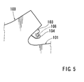
As shown inFIG 5 , afender panel 100 of a passenger vehicle is provided with a flat plate-shaped projection strip 103 that is positioned in an upper periphery of anotch portion 101 formed therein. Theprojection strip 103 has a hook-shaped engagement portion 104 that is formed in a distal end portion thereof. Theprojection strip 103 is constructed to be inserted into a space between a triangular fixed window (not shown) and a side body (not shown), so that the engagement portion 104 formed in the distal end portion thereof engages aclip 108 that is secured in the space. Thus, a circumferential periphery of thenotch portion 101 of thefender panel 100 can be secured to the side body, so that rattle cannot be easily generated around the circumferential periphery of thenotch portion 101, e.g., when the vehicle is moving. -
- Patent Document 1:
JP 2005-96502 A - For example, when the triangular fixed window should be longitudinally elongated with a design change, the
notch portion 101 of thefender panel 100 must also be longitudinally elongated. However, in the fixing structure of thefender panel 100 described above, the circumferential periphery of thenotch portion 101 can be secured to the side body at a single portion (the projection strip 103) that is positioned in an upper side thereof. Therefore, if thenotch portion 101 is enlarged, the rattle can be easily generated around a lower side portion that is spaced from an upper side securing portion (the projection strip 103). - The present invention has been made in order to solve the above-mentioned problem. It is an object of the present invention to reliably support a circumferential periphery of the notch portion of a fender panel that is fitted to a front acute angled portion of a fixed window, thereby restricting generation of rattle therein.
- The above-mentioned problem is solved by the invention of each of the claims.
A first invention provides a fender panel fixing structure of a passenger vehicle in which a triangular fixed window is attached to a side body positioned in a front side of a front door and in which a front acute angled portion of the fixed window is fitted into an acute angled notch portion that is formed in an upper rear end of a fender panel covering the side body. The notch portion of the fender panel is provided with a first flat plate-shaped projection strip that is capable of being inserted into a space between an upper end periphery of the fixed window and the side body and has an engagement portion, and a second flat plate-shaped projection strip that is capable of being inserted into a space between a lower end periphery of the fixed window and the side body and has an engagement portion. The side body has a first engaging portion and a second engaging portion that are disposed in portions covered by the upper end periphery and the lower end periphery of the fixed window. The first and second engaging portions are capable of respectively engaging the engagement portion of the first flat plate-shaped projection strip and the engagement portion of the second flat plate-shaped projection strip. The engagement portion of the first flat plate-shaped projection strip and the engagement portion of the second flat plate-shaped projection strip are constructed to respectively engage the first engaging portion and the second engaging portion when the fender panel is moved in a given direction while the first flat plate-shaped projection strip and the second flat plate-shaped projection strip of the fender panel are respectively inserted into the spaces between the fixed window and the side body. - According to the present invention, the first flat plate-shaped projection strip and the second flat plate-shaped projection strip are formed in the notch portion of the fender panel. Further, the engagement portion of the first flat plate-shaped projection strip is constructed to engage the first engaging portion within the space between the upper end periphery of the fixed window and the side body. Further, the engagement portion of the second flat plate-shaped projection strip is constructed to engage the second engaging portion within the space between the lower end periphery of the fixed window and the side body. That is, because the circumferential periphery of the notch portion of the fender panel can be connected to the side body via upper and lower sides of the fixed window, the circumferential periphery of the notch portion can be reliably supported from above and below. Therefore, even if the notch portion is enlarged, rattle cannot be easily generated therein.
Further, the engagement portion of the first flat plate-shaped projection strip and the engagement portion of the second flat plate-shaped projection strip are constructed to respectively engage the first engaging portion and the second engaging portion when the fender panel is moved in a given direction. Therefore, if a plurality of flat plate-shaped projection strips are formed in the notch portion of the fender panel, an attaching operation of the fender panel can be performed without any problem. - In a second invention, the notch portion of the fender panel is provided with a guide projection strip that is continuous with the second flat plate-shaped projection strip along a circumferential periphery of the notch portion. The engagement portion of the first flat plate-shaped projection strip and the engagement portion of the second flat plate-shaped projection strip are constructed to move to positions in which the engagement portions can respectively engage the first engaging portion and the second engaging portion when the fender panel is moved rearwardly while sliding an outer surface of the guide projection strip relative to a receiving portion formed in the fixed window in a condition in which the first flat plate-shaped projection strip and the second flat plate-shaped projection strip are respectively inserted into the spaces between the fixed window and the side body.
That is, the engagement portion of the first flat plate-shaped projection strip and the engagement portion of the second flat plate-shaped projection strip are constructed to move to positions in which they can respectively engage the first engaging portion and the second engaging portion when the fender panel is moved rearwardly while sliding the outer surface of the guide projection strip relative to the receiving portion of the fixed window. Therefore, the circumferential periphery of the notch portion of the fender panel cannot be displaced outwardly relative to the fixed window, so as to be prevented from being interfered with the fixed window while the fender panel is being moved. Thus, for example, the fender panel can be easily replaced with a new one. - In a third invention, the engagement portion of the first flat plate-shaped projection strip and the engagement portion of the second flat plate-shaped projection strip respectively have substantially U-shaped notches that are opened in the same direction. The first engaging portion and the second engaging portion respectively have shaft-shaped portions which engage the substantially U-shaped notches.
Therefore, an engagement structure of the engagement portions of the first and second flat plate-shaped projection strips and the first and second engaging portions can be simplified. - According to the present invention, the circumferential periphery of the notch portion of the fender panel can be secured to the side body via upper and lower sides of the fixed window. Therefore, the circumferential periphery of the notch portion can be reliably supported. As a result, even if the notch portion is enlarged, rattle cannot be easily generated therein.
-
-
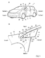
FIG. 1 shows a front pictorial perspective view (Figure A) of a passenger vehicle having a fender panel fixing structure according toEmbodiment 1 of the present invention, and an enlarged side view (Figure B) of a portion B in Figure A. -
FIG 2 is a side view of an upper rear end of a fender panel. -
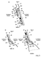
FIG 3 shows a cross-sectional view (Figure A) taken along line IIIA ofFIG 1(B) , a cross-sectional view (Figure B) taken along line IIIB ofFIG 1 (B) , and a cross-sectional view (Figure C) taken along line IIIC ofFIG 1(B) . -
FIG 4 shows a transverse cross-sectional view (Figure A), which illustrates a condition in which a second flat plate-shaped projection strip and a guide projection strip are being inserted into a space between a fixed window and a side body, and a cross-sectional view (Figure B) taken along line IV-IV ofFIG 1(B) . -
FIG 5 is a side view of an upper rear end of a conventional fender panel. -
- 12
- front door
- 14
- front pillar
- 15
- side body
- 22
- fender panel
- 30
- fixed window
- 31
- receiving portion
- 40
- fender panel clip (first engaging portion, second engaging portion)
- 44m
- deep groove (shaft-shaped portion)
- 220
- notch portion
- 225
- first flat plate-shaped projection strip
- 226
- notch (engagement portion)
- 227
- second flat plate-shaped projection strip
- 228
- notch (engagement portion)
- 229
- guide projection strip
- In the following, a fender panel fixing structure of a passenger vehicle according to
Embodiment 1 of the present invention will be described with reference toFIG 1 to FIG 4 .
Further, forward and rearward, rightward and leftward, and upward and downward in the drawings respectively correspond to forward and rearward, rightward and leftward, and upward and downward of the passenger vehicle. - As shown in
FIG 1(A) (B) , a front side surface of abody 10 of apassenger vehicle 1 is provided with afront pillar 14 and a side body 15 (not shown). Thefront pillar 14 and theside body 15 define a front end periphery of adoor opening 11 that can be closed and opened by afront door 12. Theside body 15 is disposed below thefront pillar 14. Theside body 15 is constructed to support afender panel 22 from inside while theside body 15 is covered by thefender panel 22. An opening (not shown) is formed in a boundary portion of thefront pillar 14 and theside body 15. The opening is closed by a triangular fixedwindow 30. As shown inFIG 1(A) , the fixedwindow 30 is positioned in a front side of a window frame of thefront door 12. - The
fender panel 22 is a panel that constitutes an outer envelope of afender 20 of thepassenger vehicle 1. As shown inFIG 2 , formed in an upper rear end of thefender panel 22 is a substantially V-shapednotch portion 220 of which the rearward portion is opened. Further, a front acute angled portion of the fixedwindow 30 is fitted into thenotch portion 220 of the fender panel 22 (FIG 1(B) ). - The fixed
window 30 is constructed of a transparent triangularwindow body portion 32, and anopaque resin portion 34 and arubber sealing portion 36, which are shown inFIG 3 andFIG 4 . Theresin portion 34 is laminated on an inner side end periphery of thewindow body portion 32. The sealingportion 36 is formed in a circumferential periphery of thewindow body portion 32. Further, window clips 39 are fixedly connected to theresin portion 34 of the fixedwindow 30, so as to be projected perpendicular to an inner surface of thewindow body portion 32. The window clips 39 are resin clips to attach the fixedwindow 30 to theside body 15. As shown inFIG 1(B) , the window clips 39 are disposed in a rear upper end position, a rear lower end position and a front central position of the fixedwindow 30. As shown inFIG 3(A) , the window clips 39 respectively have hookeddistal end portions 39k that are capable of elastically spreading. The hookeddistal end portions 39k are respectively constructed to be spread after they are inserted into throughholes 15h formed in theside body 15, thereby engaging inner circumferential peripheries of the throughholes 15h. That is, upon insertion of the threewindow clips 39 into the throughholes 15h of theside body 15, the fixedwindow 30 can be secured to theside body 15. Further, theresin portion 34 of the fixedwindow 30 is adhered to a circumferential periphery of the opening of theside body 15 via an adhesive 38. - As shown in
FIG 3(A), (C) , theside body 15 has spaces S that are formed in portions covered by end peripheries of the fixedwindow 30. The spaces S are positioned outside relative to the window clips 39 and theadhesives 38. Further, fender panel clips 40 are disposed in portions corresponding to the spaces S and are connected to theside body 15. The fender panel clips 40 are respectively positioned above and below thewindow clip 39 that is disposed in the front central position of the fixedwindow 30.
As shown inFIG. 3(A) , the fender panel clips 40 respectively haveretainer portions 42 that can be inserted into and connected to throughholes 15x formed in theside body 15, and disk-shapedhead portions 44. Further, in a condition that theretainer portions 42 of the fender panel clips 40 are inserted into and connected to the throughholes 15x of theside body 15, the disk-shapedhead portions 44 can be vertically secured in the spaces S between theside body 15 and the fixedwindow 30. Each of thehead portions 44 of the fender panel clips 40 has a ring-shapeddeep groove 44m that is formed in an outer circumferential surface thereof. Further, formed in a bottom portion of thedeep groove 44m is a shaft-shaped portion that is capable of engaging an engagement portion of a first flat plate-shaped projection strip 225 (an engagement portion of a second flat plate-shaped projection strip 227) which will be hereinafter described. Thedeep groove 44m is formed to be spread and opened in a V-shape in cross section toward an opening side thereof. Therefore, for example, even if the engagement portion of the first flat plate-shapedprojection strip 225 is axially displaced to a certain degree relative to thehead portion 44 of the fender panel clips 40, the engagement portion of the first flat plate-shapedprojection strip 225 is capable of engaging the shaft-shaped portion of thedeep groove 44m (hereinafter simply referred to as thedeep groove 44m) with the aid of a spread portion having a V-shape in cross section. - As shown in
FIG 2 , formed in the upper rear end of thefender panel 22 are apillar covering portion 22x that covers a lower portion of thefront pillar 14, and abody covering portion 22y that covers an upper end periphery of theside body 15. Further, formed between thepillar covering portion 22x and thebody covering portion 22y is thenotch portion 220 into which a front portion of the fixedwindow 30 is fitted.
As shown inFIG 3(A) - (C) , thenotch portion 220 has ashoulder portion 222 that is formed by inwardly folding a circumferential periphery thereof. Theshoulder portion 222 is constructed to contact the sealingportion 36 of the fixedwindow 30 in a watertight condition. Further, in an upper side (a side corresponding to thepillar covering portion 22x) of thenotch portion 220, the first flat plate-shapedprojection strip 225 is formed in a far side end position of theshoulder portion 222. As shown inFIG 2 , the first flat plate-shapedprojection strip 225 is formed by bending and is shaped to be projected downwardly. Conversely, in a lower side (a side corresponding to thebody covering portion 22y) of thenotch portion 220, the second flat plate-shapedprojection strip 227 and aguide projection strip 229 are formed in a far side end position of theshoulder portion 222. The second flat plate-shapedprojection strip 227 and theguide projection strip 229 are formed by bending and are shaped to be projected upwardly. - The first flat plate-shaped
projection strip 225 is a projection strip that is capable of engaging the upperfender panel clip 40, thereby securing an upper circumferential periphery of thenotch portion 220 of thefender panel 22 to theside body 15. As shown inFIG. 3 (A) , the first flat plate-shapedprojection strip 225 is constructed to be inserted into the space S between an upper end periphery of the fixedwindow 30 and theside body 15 from before. Further, as shown inFIG 2 , the engagement portion having anotch 226 is formed in a distal end of the first flat plate-shapedprojection strip 225. Thenotch 226 of the engagement portion has a substantially U-shape that is rearwardly opened. That is, thenotch 226 of the first flat plate-shapedprojection strip 225 is constructed to engage thedeep groove 44m of the upperfender panel clip 40 from before.
Therefore, the upperfender panel clip 40 corresponds to a first engaging portion of the present invention. - The second flat plate-shaped
projection strip 227 is a projection strip that is capable of engaging the lowerfender panel clip 40, thereby securing a lower circumferential periphery of thenotch portion 220 of thefender panel 22 to theside body 15. As shown inFIG 3(C) , the second flat plate-shapedprojection strip 227 is constructed to be inserted into the space S between a lower end periphery of the fixedwindow 30 and theside body 15 from before. Further, the engagement portion having anotch 228 is formed in a distal end of the second flat plate-shapedprojection strip 227. Thenotch 228 of the engagement portion has a substantially U-shape that is directed and opened in the same direction as thenotch 226 of the first flat plate-shaped projection strip 225 (FIG 2 ). That is, thenotch 228 of the second flat plate-shapedprojection strip 227 is constructed to engage thedeep groove 44m of the lowerfender panel clip 40 from before.
Therefore, the lowerfender panel clip 40 corresponds to a second engaging portion of the present invention. - The
guide projection strip 229 is a portion along which a receiving portion 31 (FIG 3(B) ) formed in a front inner side of the fixedwindow 30 slides when thefender panel 22 is moved rearwardly while the first flat plate-shapedprojection strip 225 and the second flat plate-shapedprojection strip 227 are respectively inserted into the spaces S between the fixedwindow 30 and theside body 15. Theguide projection strip 229 is constructed to be continuous with the second flat plate-shapedprojection strip 227 along the circumferential periphery (the shoulder portion 222) of thenotch portion 220. - In order to attach the
fender panel 22 to theside body 15 of thepassenger vehicle 1, first, the first flat plate-shapedprojection strip 225 and the second flat plate-shapedprojection strip 227 formed in thenotch portion 220 of thefender panel 22 are respectively inserted into the spaces S between the fixedwindow 30 and theside body 15 from before. At this time, as shown inFIG 3(B) , an outer surface of theguide projection strip 229 of thefender panel 22 is placed in contact with the receivingportion 31 that is formed in a lower portion of the front inner side of the fixedwindow 30.
Next, in this condition, thefender panel 22 is moved rearwardly, so as to slide theguide projection strip 229 of thefender panel 22 relative to the receivingportion 31 of the fixedwindow 30. As a result, as shown inFIG 4(A) , the circumferential periphery of thenotch portion 220 of thefender panel 22 cannot be displaced outwardly relative to the fixedwindow 30. Thus, when thefender panel 22 is moved rearwardly, the circumferential periphery of thenotch portion 220 of thefender panel 22 can be prevented from being interfered with the fixedwindow 30. - Thus, when the
fender panel 22 is moved to a position closer to a farthest rear position, the front portion of the fixedwindow 30 is fitted into thenotch portion 220 of thefender panel 22, so that as shown inFIG 4(B) , thenotch 226 of the first flat plate-shapedprojection strip 225 and thenotch 228 of the second flat plate-shapedprojection strip 227 respectively engage thedeep grooves 44m of the upper and lower fender panel clips 40. That is, thenotch 226 of the first flat plate-shapedprojection strip 225 and thenotch 228 of the second flat plate-shapedprojection strip 227 respectively engage thedeep grooves 44m of the upper and lower fender panel clips 40, so that the circumferential periphery of thenotch portion 220 of thefender panel 22 can be secured to theside body 15. - After the circumferential periphery of the
notch portion 220 of thefender panel 22 is secured to theside body 15, a flanged portion (not shown) formed in an upper end periphery of thefender panel 22, aflanged portion 22z (FIG 2 ) formed in a rear end periphery of thefender panel 22 or other such portions are secure to theside body 15 with bolts.
Further, thefender panel 22 can be detached from thepassenger vehicle 1 by performing an opposite procedure from the procedure described above. That is, upon withdrawal of thefender panel 22 forwardly after the bolts are removed, thenotches fender panel 22 can be disengaged from the fender panel clips 40 of theside body 15. - According to the present embodiment, the first flat plate-shaped
projection strip 225 and the second flat plate-shapedprojection strip 227 are formed in thenotch portion 220 of thefender panel 22. Further, thenotch 226 of the first flat plate-shapedprojection strip 225 is constructed to engage the upperfender panel clip 40 within the space S between the upper end periphery of the fixedwindow 30 and theside body 15. Further, thenotch 228 of the second flat plate-shapedprojection strip 227 is constructed to engage the lowerfender panel clip 40 within the space S between the lower end periphery of the fixedwindow 30 and theside body 15. That is, because the circumferential periphery of thenotch portion 220 of thefender panel 22 can be connected to theside body 15 via upper and lower sides of the fixedwindow 30, the circumferential periphery of thenotch portion 220 can be reliably supported from above and below. Therefore, even if thenotch portion 220 is enlarged, rattle cannot be easily generated therein.
Further, thenotch 226 of the first flat plate-shapedprojection strip 225 and thenotch 228 of the second flat plate-shapedprojection strip 227 are constructed to respectively engage the upper and lower fender panel clips 40 when thefender panel 22 is moved in a given direction (rearwardly). Therefore, if a plurality of first flat plate-shaped projection strips 225 and a plurality of second flat plate-shaped projection strips 227 are respectively formed therein, an attaching operation of thefender panel 22 can be performed without any problem. - Further, the
notch 226 of the first flat plate-shapedprojection strip 225 and thenotch 228 of the second flat plate-shapedprojection strip 227 are constructed to move to positions in which they can respectively engage the upper and lower fender panel clips 40 when thefender panel 22 is moved rearwardly while sliding the outer surface of theguide projection strip 229 relative to the receivingportion 31 formed in a front portion of the fixedwindow 30. Therefore, the circumferential periphery of thenotch portion 220 of thefender panel 22 cannot be displaced outwardly relative to the fixedwindow 30, so as to be prevented from being interfered with the fixed window while thefender panel 22 is being moved. Thus, thefender panel 22 can be easily replaced with a new one.
Further, the engagement portions of the first flat plate-shapedprojection strip 225 and the second flat plate-shapedprojection strip 227 respectively have the substantiallyU-shaped notches deep grooves 44m which engage the substantiallyU-shaped notches - The present invention is not limited to the embodiment described above and the invention can be modified without departing from the scope thereof. For example, in the embodiment, the
guide projection strip 229 of thenotch portion 220 of thefender panel 22 is formed to be continuous with the second flat plate-shapedprojection strip 227. However, a guide projection strip can be formed to be continuous with the first flat plate-shapedprojection strip 225. In such a modified form, a position of the receivingportion 31 of the fixed window is changed so as to correspond to a position of the guide projection strip.
Also, in the embodiment, thenotches projection strip 225 and the second flat plate-shapedprojection strip 227 respectively engage the upper and lower fender panel clips 40. However, the distal end of each of the first flat plate-shapedprojection strip 225 and the second flat plate-shapedprojection strip 227 can be shaped to a band plate-shape that extends rearwardly. Conversely, slit-shaped openings can be formed in a surface of theside body 15, so that the distal end of each of the first flat plate-shapedprojection strip 225 and the second flat plate-shapedprojection strip 227 can be inserted thereinto.
Further, in the embodiment, the two flat plate-shaped projection strips 225 and 227 are provided to thenotch portion 220 of thefender panel 22. However, three or more flat plate-shaped projection strips can be provided thereto.
Further, in the embodiment, the upper and lower fender panel clips 40 are constructed to support only thefender panel 22. However, the fender panel clips 40 can be constructed to support the fixedwindow 30 as well as thefender panel 22.
Claims (3)
- A fender panel fixing structure of a passenger vehicle in which a triangular fixed window is attached to a side body positioned in a front side of a front door and in which a front acute angled portion of the fixed window is fitted into an acute angled notch portion that is formed in an upper rear end of a fender panel covering the side body,
wherein the notch portion of the fender panel is provided with a first flat plate-shaped projection strip that is capable of being inserted into a space between an upper end periphery of the fixed window and the side body and has an engagement portion, and a second flat plate-shaped projection strip that is capable of being inserted into a space between a lower end periphery of the fixed window and the side body and has an engagement portion,
wherein the side body has a first engaging portion and a second engaging portion that are disposed in portions covered by the upper end periphery and the lower end periphery of the fixed window, the first and second engaging portions being capable of respectively engaging the engagement portion of the first flat plate-shaped projection strip and the engagement portion of the second flat plate-shaped projection strip, and
wherein the engagement portion of the first flat plate-shaped projection strip and the engagement portion of the second flat plate-shaped projection strip are constructed to respectively engage the first engaging portion and the second engaging portion when the fender panel is moved in a given direction while the first flat plate-shaped projection strip and the second flat plate-shaped projection strip of the fender panel are respectively inserted into the spaces between the fixed window and the side body. - A fender panel fixing structure of a passenger vehicle as defined in claim 1, wherein the notch portion of the fender panel is provided with a guide projection strip that is continuous with the second flat plate-shaped projection strip along a circumferential periphery of the notch portion, and
wherein the engagement portion of the first flat plate-shaped projection strip and the engagement portion of the second flat plate-shaped projection strip are constructed to move to positions in which the engagement portions can respectively engage the first engaging portion and the second engaging portion when the fender panel is moved rearwardly while sliding an outer surface of the guide projection strip relative to a receiving portion formed in the fixed window in a condition in which the first flat plate-shaped projection strip and the second flat plate-shaped projection strip are respectively inserted into the spaces between the fixed window and the side body. - A fender panel fixing structure of a passenger vehicle as defined in claim 1 or 2, wherein the engagement portion of the first flat plate-shaped projection strip and the engagement portion of the second flat plate-shaped projection strip respectively have substantially U-shaped notches that are opened in the same direction, and
wherein the first engaging portion and the second engaging portion respectively have shaft-shaped portions which engage the substantially U-shaped notches.
Applications Claiming Priority (2)
| Application Number | Priority Date | Filing Date | Title |
|---|---|---|---|
| JP2008151805A JP5029499B2 (en) | 2008-06-10 | 2008-06-10 | Fender panel fixing structure for passenger cars |
| PCT/JP2009/051457 WO2009150863A1 (en) | 2008-06-10 | 2009-01-29 | Structure for fixing fender panel in car |
Publications (3)
| Publication Number | Publication Date |
|---|---|
| EP2284067A1 true EP2284067A1 (en) | 2011-02-16 |
| EP2284067A4 EP2284067A4 (en) | 2011-12-07 |
| EP2284067B1 EP2284067B1 (en) | 2014-07-02 |
Family
ID=41416574
Family Applications (1)
| Application Number | Title | Priority Date | Filing Date |
|---|---|---|---|
| EP09762294.8A Not-in-force EP2284067B1 (en) | 2008-06-10 | 2009-01-29 | Structure for fixing fender panel in car |
Country Status (7)
| Country | Link |
|---|---|
| US (1) | US7988227B2 (en) |
| EP (1) | EP2284067B1 (en) |
| JP (1) | JP5029499B2 (en) |
| CN (1) | CN101959747B (en) |
| AU (1) | AU2009258725B2 (en) |
| CA (1) | CA2714616C (en) |
| WO (1) | WO2009150863A1 (en) |
Families Citing this family (10)
| Publication number | Priority date | Publication date | Assignee | Title |
|---|---|---|---|---|
| JP4996665B2 (en) * | 2009-10-19 | 2012-08-08 | 本田技研工業株式会社 | Body structure of pillar garnish and fender panel |
| US9022428B2 (en) * | 2011-11-02 | 2015-05-05 | Nissan North America, Inc. | Vehicle splash guard |
| EP2805876B1 (en) | 2012-01-20 | 2016-09-28 | Honda Motor Co., Ltd. | Fender panel mounting structure for vehicle |
| US20140035309A1 (en) * | 2012-08-02 | 2014-02-06 | Toyota Motor Engineering & Manufacturing North America, Inc. | Vehicle body expansion foam |
| KR101394035B1 (en) * | 2012-10-09 | 2014-05-09 | 기아자동차 주식회사 | Connecting structure for fender apron |
| JP6099451B2 (en) * | 2013-03-26 | 2017-03-22 | ダイハツ工業株式会社 | Vehicle fender panel structure |
| JP2017007483A (en) * | 2015-06-19 | 2017-01-12 | 日本板硝子株式会社 | Glass plate module |
| JP7014090B2 (en) * | 2018-08-03 | 2022-02-01 | トヨタ自動車株式会社 | Fender panel fixed structure |
| JP6928069B2 (en) * | 2019-11-28 | 2021-09-01 | 本田技研工業株式会社 | Vehicle front structure |
| KR20250014925A (en) * | 2023-07-24 | 2025-02-03 | 현대자동차주식회사 | Structure for Quadrant Cover |
Family Cites Families (8)
| Publication number | Priority date | Publication date | Assignee | Title |
|---|---|---|---|---|
| US4717197A (en) * | 1985-03-30 | 1988-01-05 | Mazda Motor Corporation | Automobile body side structure |
| DE3809456C2 (en) * | 1987-03-27 | 1995-06-14 | Nissan Motor | Vehicle body and method of manufacturing the same |
| DE4018592A1 (en) * | 1990-06-09 | 1991-12-12 | Porsche Ag | BODY FOR A MOTOR VEHICLE, ESPECIALLY A PASSENGER VEHICLE |
| JP3413284B2 (en) * | 1994-07-07 | 2003-06-03 | 本田技研工業株式会社 | Front fender reinforcement structure |
| CN2633706Y (en) * | 2003-07-22 | 2004-08-18 | 关瑞朋 | Novel motor vehicle mud guard |
| JP4206878B2 (en) * | 2003-09-22 | 2009-01-14 | トヨタ車体株式会社 | Car fender panel mounting structure |
| JP2006213295A (en) * | 2005-02-07 | 2006-08-17 | Honda Motor Co Ltd | Front fender reinforcement structure |
| DE602007001555D1 (en) * | 2006-05-10 | 2009-08-27 | Mazda Motor | Vehicle body construction |
-
2008
- 2008-06-10 JP JP2008151805A patent/JP5029499B2/en not_active Expired - Fee Related
-
2009
- 2009-01-29 EP EP09762294.8A patent/EP2284067B1/en not_active Not-in-force
- 2009-01-29 CN CN2009801069891A patent/CN101959747B/en not_active Expired - Fee Related
- 2009-01-29 US US12/918,994 patent/US7988227B2/en not_active Expired - Fee Related
- 2009-01-29 AU AU2009258725A patent/AU2009258725B2/en not_active Ceased
- 2009-01-29 CA CA2714616A patent/CA2714616C/en not_active Expired - Fee Related
- 2009-01-29 WO PCT/JP2009/051457 patent/WO2009150863A1/en not_active Ceased
Also Published As
| Publication number | Publication date |
|---|---|
| WO2009150863A1 (en) | 2009-12-17 |
| CN101959747A (en) | 2011-01-26 |
| JP2009298185A (en) | 2009-12-24 |
| CA2714616C (en) | 2012-07-10 |
| US20110049934A1 (en) | 2011-03-03 |
| AU2009258725A1 (en) | 2009-12-17 |
| JP5029499B2 (en) | 2012-09-19 |
| CA2714616A1 (en) | 2009-12-17 |
| EP2284067A4 (en) | 2011-12-07 |
| AU2009258725B2 (en) | 2012-09-20 |
| US7988227B2 (en) | 2011-08-02 |
| EP2284067B1 (en) | 2014-07-02 |
| CN101959747B (en) | 2012-07-18 |
Similar Documents
| Publication | Publication Date | Title |
|---|---|---|
| EP2284067B1 (en) | Structure for fixing fender panel in car | |
| US8677573B2 (en) | Two stage serviceable safety clip | |
| US8776475B2 (en) | DLO molding with dutch bend feature and clip retention feature | |
| US7878580B2 (en) | Roof assembly for a vehicle | |
| JP6545730B2 (en) | Mounting structure of door frame molding | |
| JP2015217926A (en) | Cowl cover device | |
| JP5630201B2 (en) | Split windows for vehicles | |
| JP4261746B2 (en) | Sliding device | |
| JP2015016816A (en) | Belt molding structure of automobile door | |
| KR101407321B1 (en) | Assembling structure of undercover of vehicle | |
| US11623588B2 (en) | Method and apparatus for fastening hard and soft top appliques | |
| JP6896571B2 (en) | Vehicle sun visor | |
| JP6543521B2 (en) | Mounting structure of automotive door seal | |
| US11358503B1 (en) | Seal for a trim member of a vehicle seat back | |
| JP2022048562A (en) | Mounting structure of roof lining | |
| JP2005263011A (en) | Pillar garnish assembly structure | |
| WO2019181567A1 (en) | Side sill garnish attachment structure | |
| CN210390716U (en) | Sunroof device | |
| JP6163002B2 (en) | Side decorative panel | |
| KR100612730B1 (en) | Rail structure of car seat | |
| KR100950072B1 (en) | Automotive Anchor Clip Assembly | |
| JP2013216161A (en) | Retainer for mounting bumper and bumper mounting structure | |
| JP6969280B2 (en) | Vehicle interior parts mounting structure and vehicle equipped with the mounting structure | |
| JP2006062433A (en) | Cover member mounting structure for vehicle bumper | |
| JP2023129197A (en) | Automotive door seal structure |
Legal Events
| Date | Code | Title | Description |
|---|---|---|---|
| PUAI | Public reference made under article 153(3) epc to a published international application that has entered the european phase |
Free format text: ORIGINAL CODE: 0009012 |
|
| 17P | Request for examination filed |
Effective date: 20100824 |
|
| AK | Designated contracting states |
Kind code of ref document: A1 Designated state(s): AT BE BG CH CY CZ DE DK EE ES FI FR GB GR HR HU IE IS IT LI LT LU LV MC MK MT NL NO PL PT RO SE SI SK TR |
|
| AX | Request for extension of the european patent |
Extension state: AL BA RS |
|
| DAX | Request for extension of the european patent (deleted) | ||
| A4 | Supplementary search report drawn up and despatched |
Effective date: 20111104 |
|
| RIC1 | Information provided on ipc code assigned before grant |
Ipc: B60J 1/00 20060101ALI20111028BHEP Ipc: B60J 1/10 20060101ALI20111028BHEP Ipc: B62D 25/16 20060101AFI20111028BHEP |
|
| 17Q | First examination report despatched |
Effective date: 20131122 |
|
| GRAP | Despatch of communication of intention to grant a patent |
Free format text: ORIGINAL CODE: EPIDOSNIGR1 |
|
| INTG | Intention to grant announced |
Effective date: 20140127 |
|
| GRAS | Grant fee paid |
Free format text: ORIGINAL CODE: EPIDOSNIGR3 |
|
| GRAA | (expected) grant |
Free format text: ORIGINAL CODE: 0009210 |
|
| AK | Designated contracting states |
Kind code of ref document: B1 Designated state(s): AT BE BG CH CY CZ DE DK EE ES FI FR GB GR HR HU IE IS IT LI LT LU LV MC MK MT NL NO PL PT RO SE SI SK TR |
|
| REG | Reference to a national code |
Ref country code: GB Ref legal event code: FG4D |
|
| REG | Reference to a national code |
Ref country code: CH Ref legal event code: EP Ref country code: AT Ref legal event code: REF Ref document number: 675748 Country of ref document: AT Kind code of ref document: T Effective date: 20140715 |
|
| REG | Reference to a national code |
Ref country code: IE Ref legal event code: FG4D |
|
| REG | Reference to a national code |
Ref country code: DE Ref legal event code: R096 Ref document number: 602009025108 Country of ref document: DE Effective date: 20140814 |
|
| REG | Reference to a national code |
Ref country code: NL Ref legal event code: T3 |
|
| REG | Reference to a national code |
Ref country code: AT Ref legal event code: MK05 Ref document number: 675748 Country of ref document: AT Kind code of ref document: T Effective date: 20140702 |
|
| REG | Reference to a national code |
Ref country code: LT Ref legal event code: MG4D |
|
| REG | Reference to a national code |
Ref country code: FR Ref legal event code: PLFP Year of fee payment: 7 |
|
| PG25 | Lapsed in a contracting state [announced via postgrant information from national office to epo] |
Ref country code: BG Free format text: LAPSE BECAUSE OF FAILURE TO SUBMIT A TRANSLATION OF THE DESCRIPTION OR TO PAY THE FEE WITHIN THE PRESCRIBED TIME-LIMIT Effective date: 20141002 Ref country code: NO Free format text: LAPSE BECAUSE OF FAILURE TO SUBMIT A TRANSLATION OF THE DESCRIPTION OR TO PAY THE FEE WITHIN THE PRESCRIBED TIME-LIMIT Effective date: 20141002 Ref country code: GR Free format text: LAPSE BECAUSE OF FAILURE TO SUBMIT A TRANSLATION OF THE DESCRIPTION OR TO PAY THE FEE WITHIN THE PRESCRIBED TIME-LIMIT Effective date: 20141003 Ref country code: LT Free format text: LAPSE BECAUSE OF FAILURE TO SUBMIT A TRANSLATION OF THE DESCRIPTION OR TO PAY THE FEE WITHIN THE PRESCRIBED TIME-LIMIT Effective date: 20140702 Ref country code: PT Free format text: LAPSE BECAUSE OF FAILURE TO SUBMIT A TRANSLATION OF THE DESCRIPTION OR TO PAY THE FEE WITHIN THE PRESCRIBED TIME-LIMIT Effective date: 20141103 Ref country code: CZ Free format text: LAPSE BECAUSE OF FAILURE TO SUBMIT A TRANSLATION OF THE DESCRIPTION OR TO PAY THE FEE WITHIN THE PRESCRIBED TIME-LIMIT Effective date: 20140702 Ref country code: FI Free format text: LAPSE BECAUSE OF FAILURE TO SUBMIT A TRANSLATION OF THE DESCRIPTION OR TO PAY THE FEE WITHIN THE PRESCRIBED TIME-LIMIT Effective date: 20140702 Ref country code: ES Free format text: LAPSE BECAUSE OF FAILURE TO SUBMIT A TRANSLATION OF THE DESCRIPTION OR TO PAY THE FEE WITHIN THE PRESCRIBED TIME-LIMIT Effective date: 20140702 Ref country code: SE Free format text: LAPSE BECAUSE OF FAILURE TO SUBMIT A TRANSLATION OF THE DESCRIPTION OR TO PAY THE FEE WITHIN THE PRESCRIBED TIME-LIMIT Effective date: 20140702 |
|
| PG25 | Lapsed in a contracting state [announced via postgrant information from national office to epo] |
Ref country code: PL Free format text: LAPSE BECAUSE OF FAILURE TO SUBMIT A TRANSLATION OF THE DESCRIPTION OR TO PAY THE FEE WITHIN THE PRESCRIBED TIME-LIMIT Effective date: 20140702 Ref country code: LV Free format text: LAPSE BECAUSE OF FAILURE TO SUBMIT A TRANSLATION OF THE DESCRIPTION OR TO PAY THE FEE WITHIN THE PRESCRIBED TIME-LIMIT Effective date: 20140702 Ref country code: CY Free format text: LAPSE BECAUSE OF FAILURE TO SUBMIT A TRANSLATION OF THE DESCRIPTION OR TO PAY THE FEE WITHIN THE PRESCRIBED TIME-LIMIT Effective date: 20140702 Ref country code: IS Free format text: LAPSE BECAUSE OF FAILURE TO SUBMIT A TRANSLATION OF THE DESCRIPTION OR TO PAY THE FEE WITHIN THE PRESCRIBED TIME-LIMIT Effective date: 20141102 Ref country code: AT Free format text: LAPSE BECAUSE OF FAILURE TO SUBMIT A TRANSLATION OF THE DESCRIPTION OR TO PAY THE FEE WITHIN THE PRESCRIBED TIME-LIMIT Effective date: 20140702 Ref country code: HR Free format text: LAPSE BECAUSE OF FAILURE TO SUBMIT A TRANSLATION OF THE DESCRIPTION OR TO PAY THE FEE WITHIN THE PRESCRIBED TIME-LIMIT Effective date: 20140702 |
|
| PGFP | Annual fee paid to national office [announced via postgrant information from national office to epo] |
Ref country code: NL Payment date: 20150129 Year of fee payment: 7 |
|
| REG | Reference to a national code |
Ref country code: DE Ref legal event code: R097 Ref document number: 602009025108 Country of ref document: DE |
|
| PG25 | Lapsed in a contracting state [announced via postgrant information from national office to epo] |
Ref country code: SK Free format text: LAPSE BECAUSE OF FAILURE TO SUBMIT A TRANSLATION OF THE DESCRIPTION OR TO PAY THE FEE WITHIN THE PRESCRIBED TIME-LIMIT Effective date: 20140702 Ref country code: EE Free format text: LAPSE BECAUSE OF FAILURE TO SUBMIT A TRANSLATION OF THE DESCRIPTION OR TO PAY THE FEE WITHIN THE PRESCRIBED TIME-LIMIT Effective date: 20140702 Ref country code: DK Free format text: LAPSE BECAUSE OF FAILURE TO SUBMIT A TRANSLATION OF THE DESCRIPTION OR TO PAY THE FEE WITHIN THE PRESCRIBED TIME-LIMIT Effective date: 20140702 Ref country code: IT Free format text: LAPSE BECAUSE OF FAILURE TO SUBMIT A TRANSLATION OF THE DESCRIPTION OR TO PAY THE FEE WITHIN THE PRESCRIBED TIME-LIMIT Effective date: 20140702 Ref country code: RO Free format text: LAPSE BECAUSE OF FAILURE TO SUBMIT A TRANSLATION OF THE DESCRIPTION OR TO PAY THE FEE WITHIN THE PRESCRIBED TIME-LIMIT Effective date: 20140702 |
|
| PGFP | Annual fee paid to national office [announced via postgrant information from national office to epo] |
Ref country code: DE Payment date: 20150121 Year of fee payment: 7 |
|
| PLBE | No opposition filed within time limit |
Free format text: ORIGINAL CODE: 0009261 |
|
| STAA | Information on the status of an ep patent application or granted ep patent |
Free format text: STATUS: NO OPPOSITION FILED WITHIN TIME LIMIT |
|
| PGFP | Annual fee paid to national office [announced via postgrant information from national office to epo] |
Ref country code: GB Payment date: 20150102 Year of fee payment: 7 Ref country code: FR Payment date: 20150122 Year of fee payment: 7 |
|
| 26N | No opposition filed |
Effective date: 20150407 |
|
| PG25 | Lapsed in a contracting state [announced via postgrant information from national office to epo] |
Ref country code: BE Free format text: LAPSE BECAUSE OF NON-PAYMENT OF DUE FEES Effective date: 20150131 |
|
| REG | Reference to a national code |
Ref country code: CH Ref legal event code: PL |
|
| PG25 | Lapsed in a contracting state [announced via postgrant information from national office to epo] |
Ref country code: LU Free format text: LAPSE BECAUSE OF FAILURE TO SUBMIT A TRANSLATION OF THE DESCRIPTION OR TO PAY THE FEE WITHIN THE PRESCRIBED TIME-LIMIT Effective date: 20150129 |
|
| PG25 | Lapsed in a contracting state [announced via postgrant information from national office to epo] |
Ref country code: MC Free format text: LAPSE BECAUSE OF FAILURE TO SUBMIT A TRANSLATION OF THE DESCRIPTION OR TO PAY THE FEE WITHIN THE PRESCRIBED TIME-LIMIT Effective date: 20140702 |
|
| PG25 | Lapsed in a contracting state [announced via postgrant information from national office to epo] |
Ref country code: CH Free format text: LAPSE BECAUSE OF NON-PAYMENT OF DUE FEES Effective date: 20150131 Ref country code: LI Free format text: LAPSE BECAUSE OF NON-PAYMENT OF DUE FEES Effective date: 20150131 |
|
| REG | Reference to a national code |
Ref country code: IE Ref legal event code: MM4A |
|
| PG25 | Lapsed in a contracting state [announced via postgrant information from national office to epo] |
Ref country code: SI Free format text: LAPSE BECAUSE OF FAILURE TO SUBMIT A TRANSLATION OF THE DESCRIPTION OR TO PAY THE FEE WITHIN THE PRESCRIBED TIME-LIMIT Effective date: 20140702 |
|
| PG25 | Lapsed in a contracting state [announced via postgrant information from national office to epo] |
Ref country code: IE Free format text: LAPSE BECAUSE OF NON-PAYMENT OF DUE FEES Effective date: 20150129 |
|
| PG25 | Lapsed in a contracting state [announced via postgrant information from national office to epo] |
Ref country code: BE Free format text: LAPSE BECAUSE OF FAILURE TO SUBMIT A TRANSLATION OF THE DESCRIPTION OR TO PAY THE FEE WITHIN THE PRESCRIBED TIME-LIMIT Effective date: 20140702 |
|
| REG | Reference to a national code |
Ref country code: DE Ref legal event code: R119 Ref document number: 602009025108 Country of ref document: DE |
|
| GBPC | Gb: european patent ceased through non-payment of renewal fee |
Effective date: 20160129 |
|
| REG | Reference to a national code |
Ref country code: NL Ref legal event code: MM Effective date: 20160201 |
|
| REG | Reference to a national code |
Ref country code: FR Ref legal event code: ST Effective date: 20160930 |
|
| PG25 | Lapsed in a contracting state [announced via postgrant information from national office to epo] |
Ref country code: DE Free format text: LAPSE BECAUSE OF NON-PAYMENT OF DUE FEES Effective date: 20160802 Ref country code: GB Free format text: LAPSE BECAUSE OF NON-PAYMENT OF DUE FEES Effective date: 20160129 |
|
| PG25 | Lapsed in a contracting state [announced via postgrant information from national office to epo] |
Ref country code: NL Free format text: LAPSE BECAUSE OF NON-PAYMENT OF DUE FEES Effective date: 20160201 Ref country code: FR Free format text: LAPSE BECAUSE OF NON-PAYMENT OF DUE FEES Effective date: 20160201 |
|
| PG25 | Lapsed in a contracting state [announced via postgrant information from national office to epo] |
Ref country code: MT Free format text: LAPSE BECAUSE OF FAILURE TO SUBMIT A TRANSLATION OF THE DESCRIPTION OR TO PAY THE FEE WITHIN THE PRESCRIBED TIME-LIMIT Effective date: 20140702 |
|
| PG25 | Lapsed in a contracting state [announced via postgrant information from national office to epo] |
Ref country code: HU Free format text: LAPSE BECAUSE OF FAILURE TO SUBMIT A TRANSLATION OF THE DESCRIPTION OR TO PAY THE FEE WITHIN THE PRESCRIBED TIME-LIMIT; INVALID AB INITIO Effective date: 20090129 |
|
| PG25 | Lapsed in a contracting state [announced via postgrant information from national office to epo] |
Ref country code: TR Free format text: LAPSE BECAUSE OF FAILURE TO SUBMIT A TRANSLATION OF THE DESCRIPTION OR TO PAY THE FEE WITHIN THE PRESCRIBED TIME-LIMIT Effective date: 20140702 |
|
| PG25 | Lapsed in a contracting state [announced via postgrant information from national office to epo] |
Ref country code: MK Free format text: LAPSE BECAUSE OF FAILURE TO SUBMIT A TRANSLATION OF THE DESCRIPTION OR TO PAY THE FEE WITHIN THE PRESCRIBED TIME-LIMIT Effective date: 20140702 |