EP2283496B1 - Variable width transverse flux electric induction coils - Google Patents
Variable width transverse flux electric induction coils Download PDFInfo
- Publication number
- EP2283496B1 EP2283496B1 EP09731695.4A EP09731695A EP2283496B1 EP 2283496 B1 EP2283496 B1 EP 2283496B1 EP 09731695 A EP09731695 A EP 09731695A EP 2283496 B1 EP2283496 B1 EP 2283496B1
- Authority
- EP
- European Patent Office
- Prior art keywords
- section
- fixed
- coil
- sections
- moveable
- Prior art date
- Legal status (The legal status is an assumption and is not a legal conclusion. Google has not performed a legal analysis and makes no representation as to the accuracy of the status listed.)
- Active
Links
Images


Classifications
-
- H—ELECTRICITY
- H01—ELECTRIC ELEMENTS
- H01F—MAGNETS; INDUCTANCES; TRANSFORMERS; SELECTION OF MATERIALS FOR THEIR MAGNETIC PROPERTIES
- H01F27/00—Details of transformers or inductances, in general
- H01F27/28—Coils; Windings; Conductive connections
-
- H—ELECTRICITY
- H05—ELECTRIC TECHNIQUES NOT OTHERWISE PROVIDED FOR
- H05B—ELECTRIC HEATING; ELECTRIC LIGHT SOURCES NOT OTHERWISE PROVIDED FOR; CIRCUIT ARRANGEMENTS FOR ELECTRIC LIGHT SOURCES, IN GENERAL
- H05B6/00—Heating by electric, magnetic or electromagnetic fields
- H05B6/02—Induction heating
- H05B6/10—Induction heating apparatus, other than furnaces, for specific applications
- H05B6/101—Induction heating apparatus, other than furnaces, for specific applications for local heating of metal pieces
- H05B6/103—Induction heating apparatus, other than furnaces, for specific applications for local heating of metal pieces multiple metal pieces successively being moved close to the inductor
- H05B6/104—Induction heating apparatus, other than furnaces, for specific applications for local heating of metal pieces multiple metal pieces successively being moved close to the inductor metal pieces being elongated like wires or bands
-
- H—ELECTRICITY
- H05—ELECTRIC TECHNIQUES NOT OTHERWISE PROVIDED FOR
- H05B—ELECTRIC HEATING; ELECTRIC LIGHT SOURCES NOT OTHERWISE PROVIDED FOR; CIRCUIT ARRANGEMENTS FOR ELECTRIC LIGHT SOURCES, IN GENERAL
- H05B6/00—Heating by electric, magnetic or electromagnetic fields
- H05B6/02—Induction heating
- H05B6/10—Induction heating apparatus, other than furnaces, for specific applications
-
- H—ELECTRICITY
- H05—ELECTRIC TECHNIQUES NOT OTHERWISE PROVIDED FOR
- H05B—ELECTRIC HEATING; ELECTRIC LIGHT SOURCES NOT OTHERWISE PROVIDED FOR; CIRCUIT ARRANGEMENTS FOR ELECTRIC LIGHT SOURCES, IN GENERAL
- H05B6/00—Heating by electric, magnetic or electromagnetic fields
- H05B6/02—Induction heating
- H05B6/36—Coil arrangements
- H05B6/362—Coil arrangements with flat coil conductors
-
- H—ELECTRICITY
- H05—ELECTRIC TECHNIQUES NOT OTHERWISE PROVIDED FOR
- H05B—ELECTRIC HEATING; ELECTRIC LIGHT SOURCES NOT OTHERWISE PROVIDED FOR; CIRCUIT ARRANGEMENTS FOR ELECTRIC LIGHT SOURCES, IN GENERAL
- H05B6/00—Heating by electric, magnetic or electromagnetic fields
- H05B6/02—Induction heating
- H05B6/36—Coil arrangements
- H05B6/40—Establishing desired heat distribution, e.g. to heat particular parts of workpieces
-
- C—CHEMISTRY; METALLURGY
- C21—METALLURGY OF IRON
- C21D—MODIFYING THE PHYSICAL STRUCTURE OF FERROUS METALS; GENERAL DEVICES FOR HEAT TREATMENT OF FERROUS OR NON-FERROUS METALS OR ALLOYS; MAKING METAL MALLEABLE, e.g. BY DECARBURISATION OR TEMPERING
- C21D9/00—Heat treatment, e.g. annealing, hardening, quenching or tempering, adapted for particular articles; Furnaces therefor
- C21D9/52—Heat treatment, e.g. annealing, hardening, quenching or tempering, adapted for particular articles; Furnaces therefor for wires; for strips ; for rods of unlimited length
- C21D9/54—Furnaces for treating strips or wire
- C21D9/56—Continuous furnaces for strip or wire
- C21D9/60—Continuous furnaces for strip or wire with induction heating
-
- H—ELECTRICITY
- H05—ELECTRIC TECHNIQUES NOT OTHERWISE PROVIDED FOR
- H05B—ELECTRIC HEATING; ELECTRIC LIGHT SOURCES NOT OTHERWISE PROVIDED FOR; CIRCUIT ARRANGEMENTS FOR ELECTRIC LIGHT SOURCES, IN GENERAL
- H05B2206/00—Aspects relating to heating by electric, magnetic, or electromagnetic fields covered by group H05B6/00
- H05B2206/02—Induction heating
- H05B2206/022—Special supports for the induction coils
-
- H—ELECTRICITY
- H05—ELECTRIC TECHNIQUES NOT OTHERWISE PROVIDED FOR
- H05B—ELECTRIC HEATING; ELECTRIC LIGHT SOURCES NOT OTHERWISE PROVIDED FOR; CIRCUIT ARRANGEMENTS FOR ELECTRIC LIGHT SOURCES, IN GENERAL
- H05B6/00—Heating by electric, magnetic or electromagnetic fields
- H05B6/02—Induction heating
- H05B6/36—Coil arrangements
-
- Y—GENERAL TAGGING OF NEW TECHNOLOGICAL DEVELOPMENTS; GENERAL TAGGING OF CROSS-SECTIONAL TECHNOLOGIES SPANNING OVER SEVERAL SECTIONS OF THE IPC; TECHNICAL SUBJECTS COVERED BY FORMER USPC CROSS-REFERENCE ART COLLECTIONS [XRACs] AND DIGESTS
- Y02—TECHNOLOGIES OR APPLICATIONS FOR MITIGATION OR ADAPTATION AGAINST CLIMATE CHANGE
- Y02P—CLIMATE CHANGE MITIGATION TECHNOLOGIES IN THE PRODUCTION OR PROCESSING OF GOODS
- Y02P10/00—Technologies related to metal processing
- Y02P10/25—Process efficiency
Definitions
- the present invention relates to transverse flux electric induction coils, and in particular, to such induction coils when used to heat a stationary or moving planarly oriented electrically conductive workpiece.
- United States Patent No. 6,570,141 B2 discloses a variable width transverse flux coil that includes moveable sections of the coil that are connected to a power supply. Such an arrangement requires flexible power connections between the coil sections and power supply, and requires moveable assemblies that are large since their lengths are directly related to the maximum width of the strip to be heated, and, as a consequence, are heavy, particularly if they include magnetic flux concentrators.
- Document JP H08 165517 A discloses an electric induction coil for heating a circular workpiece and formed from a combination of a fixed coil section and a moveable coil section and wherein both the fixed coil section and the moveable coil section have separate and overlapping pairs of axial coil sections.
- It is another object of the present invention to provide a transverse flux electric induction coil comprising a fixed powered coil section and one or more moveable passive coil sections that provide a convenient means for adjusting a transverse end, or ends of the coil if the position of the electrically conductive workpiece being inductively heated wanders, or weaves, in the transverse direction during the heating process.
- the moveable passive coil sections can be substantially shorter than the width of the electrically conductive workpiece. Consequently they are lightweight and can easily be moved to track the instantaneous positions of the opposing edges of the electrically conductive workpieces.
- the present invention is an apparatus for, transverse flux electric induction heating of a planarly oriented electrically conductive workpiece that may be in the form of a continuous or discrete sheet or strip in accordance with claim 1.
- the present invention is method of inductively heating at least one side of planarly oriented electrically conductive workpiece (90) with the transverse flux electric induction coil in accordance with claim 13. Further embodiments are disclosed in the dependent claims.
- workpiece refers to a planarly oriented electrically conductive material that may be in the form of a strip or sheet, either continuous, or consisting of strips or sheets having discrete lengths.
- the workpiece may be inductively heated either to change the metallurgical properties of the workpiece, or to achieve a bonding process, such as, but not limited to, drying a liquid bonding material deposited on a surface of the workpiece. Further the workpiece may move above, below or between one or more of the transverse flux electric induction coils of the present invention, or be stationary above, below or between the one or more coils during inductive heating of the workpiece.
- transverse flux induction coils of the present invention While the below examples of the invention generally describe a pair of transverse flux induction coils of the present invention positioned on opposing sides of the workpiece, in other examples of the invention, only one transverse flux induction coil of the present invention may be used over one side of the workpiece.
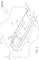
- FIG. 1 , FIG. 2 and FIG. 3 one example of the transverse flux electric induction coil assembly of the present invention.
- An orthogonal reference space is established with the X-Y plane defining the plane of workpiece 90, which, in this non-limiting example, moves between upper and lower induction coils ( FIG. 3 ) in the positive X-direction, as indicated by the direction of the arrow, with the width, or transverse, of the workpiece defined in the Y-direction.
- the positive Z-direction points in the direction perpendicular to the upper surface of the workpiece.
- the upper or lower induction coil comprises a fixed powered coil section and two moveable passive coil sections as further described below.
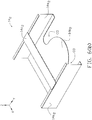
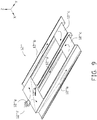
- FIG. 1 illustrates one non-limiting example of a fixed powered coil section of the present invention.
- the fixed powered coil section is used in an upper induction coil with positional reference to workpiece 90.
- Only one moveable passive coil section 14 is shown (in dashed lines) in FIG. 1 to illustrate positioning of a moveable passive coil section relative to the fixed powered coil section.
- While generally moveable passive coil sections are utilized at each opposing end of the fixed coil section, in some application the arrangement may be asymmetric with a moveable passive coil section at only one end of the fixed coil section.
- Fixed powered coil section 12 has its length, L, oriented (in the Y-direction) substantially perpendicular to the direction (X-direction) of the workpiece passing below coil section 12, as indicated by the arrow labeled WORKPIECE DIRECTION. In other examples of the invention, the length of the fixed powered coil section may be skewed from perpendicular relative to the direction of the workpiece.
- Fixed powered coil section 12 comprises bridge sections 12a at opposing ends of section 12. The bridge sections are connected to leg sections 12b by riser sections 12c.
- Leg sections 12b are a pair of transverse sections co-planarly spaced apart from each other and joined together near each adjacent opposing ends 12b' and 12b" with a bridge section 12a by means of interconnecting riser sections 12c, which extend away from the surface of workpiece 90.
- one of the bridge sections 12a is utilized to connect coil section 12 to an alternating current (AC) power supply not shown in the figure.
- AC alternating current
- the fixed powered coil section may be formed from any suitable electrically conductive material, such as a copper alloy, formed, for example, as a sheet, tube or extrusion.
- the powered coil section may be fabricated from a continuous piece of material or suitably joined sections. If cooling of the coil section is required, one or more cooling passages may be provided within the coil section or external to the coil section, for example, by at least partially surrounding the coil section with a tubular material providing the cooling passages. A cooling medium, such as water, may be supplied through the cooling passages.
- the fixed powered coil section may be formed as a single turn coil, or as a multi-turn coil.
- fixed powered coil section 12' comprises a three turn coil shown in spatial orientation for use in an upper induction coil.
- Each of the three coil turns 12' 1 , 12' 2 and 12' 3 has its own bridge (12a 1 , 12a 2 and 12a 3 ), leg (12b 1 , 12b 2 and 12b 3 ), and riser (12c 1 , 12c 2 and 12c 3 ) sections, with the sections in each coil turn electrically isolated from each other.
- Opposing ends 12d and 12e of the combination of the three coil turns are suitably connected to an AC power supply.
- the fixed powered coil section may be formed as a single loop coil, or as a multi-loop coil.
- fixed powered coil section 12" comprises a double loop coil shown in spatial orientation for use in an upper induction coil.
- Instantaneous AC current flow may be as indicated by the arrows in the figure. That is current flows from an AC power source (not shown in the figure) connected to terminal 12"e into bridge section 12"a connecting to outer leg sections 12"b, and then through bridge sections 12"c connecting each outer leg section to common return middle leg section 12"d, which terminates at a return connection 12"f to the AC power source.
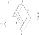
- FIG. 2 illustrates one non-limiting example of a moveable passive coil section of the present invention shown in spatial orientation for use in an upper coil assembly as illustrated, for example, in dashed lines in FIG. 1 .
- Moveable passive coil section 14 is box-like in shape, namely a three sided, open ended box, or "drawer" structure having opposing side sections 14a joined by bridge section 14b. Slat section 14c connecting opposing side sections 14a provides brace support to maintain the box structure and a closed electrical path around the side sections of the moveable passive coil section.
- the movable passive coil section may be fabricated from a continuous piece of material or suitably joined sections.
- one or more cooling passages may be provided within the coil section or external to the coil section, for example, by at least partially surrounding the coil section with a tubular material providing the cooling passages.
- a cooling medium such as water, may be supplied through the cooling passages.
- the moveable passive coil section may be formed as a single turn coil, as shown in FIG. 2 , or as a multi-turn coil that is used in combination with a single or multi-turn fixed powered coil section.
- FIG. 3 illustrates one non-limiting arrangement of a pair of transverse flux induction coils 16a and 16b of the present invention that comprises an upper and lower induction coil, respectively.
- Each transverse flux induction coil comprises a fixed powered coil section 12 and a pair of moveable passive coil sections 14.
- Movable passive coil sections 14 are configured to fit in the space bounded by the workpiece facing surface of the coil bridge sections 12a and the interior surfaces of riser sections 12c.
- the workpiece facing bridge section 14b of the passive coil sections may lie in the same horizontal plane as the leg sections 12b adjacent to the workpiece facing bridge section of the moveable section.
- the workpiece facing bridge sections 14b may be formed with areas closer to, or farther away from, the workpiece surface depending upon the induction heating temperature profiles desired at the edges of the workpiece above or below the moveable passive coil sections.
- Electrical insulation is provided at least between interfacing surfaces of the fixed powered coil section 12 and the moveable passive coil sections 14.
- the electrical insulation may be in the form of a separate insulating material or an insulative coating applied to either the appropriate sections of the fixed or moveable (or both coil sections.
- coil sections 14 can be moved (slid) in a direction (Y-direction) transverse to the edges of the workpiece to accommodate workpieces of different widths; to alter edge heating patterns of the workpiece; or to have the width of the upper and lower coil assemblies track the edges of a workpiece moving in a direction (weaving in the Y-direction) perpendicular to the movement of the workpiece between the upper and lower induction coil.
- Movement of a moveable passive coil section is similar to that of a drawer in an enclosure where the drawer is the moveable passive coil section, and the volume defined by the interior of bridge 12a and riser 12c sections is the enclosure.
- Each fixed powered coil section and associated pair of moveable passive coil sections perform electrically as a transformer with one primary (fixed section) and two secondaries (movable sections). That is current supplied to the fixed powered coil section flows through the fixed powered coil section and generates electromagnetic flux that magnetically couples with the associated pair of passive coil sections to induce a current flow in the associated passive coil sections. Current flow in a passive coil section generates a secondary electromagnetic flux that couples with the workpiece to inductively heat the workpiece.
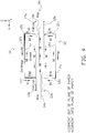
- FIG. 4 illustrates instantaneous AC current flow patterns (in directions indicated by the arrows) in fixed powered coil sections 12 (current designated I c ) and associated moveable passive sections 14 (current designated I d ).
- Maximum inward and maximum outward allowable movement (Y-direction) of the passive coil sections is defined by the minimum flux coupling sustainable for a particular application.
- One approach to maintaining the minimum flux coupling substantially independent of the position of the moveable section relative to the fixed powered coil section is to make slat 14c of the moveable section substantially narrower (in the Y-direction) than bridge 12a of the fixed section.
- a relatively wide moveable slat 34c is coupled with a substantially narrower fixed bridge 32a
- FIG. 5 illustrates the use of magnetic cores 20 to concentrate and magnify the electromagnetic coupling between a fixed powered section and associated moveable passive section enclosed by the magnetic cores.
- two cores are shown in FIG. 5 any number of cores may be used depending upon a particular application.
- Making slat 14c of the enclosed moveable passive coil section narrower (in the Y-direction) than bridge 12a of the fixed powered coil section allows the enclosed moveable section to move (slide) in the Y -direction relative to the fixed powered coil section to accommodate workpieces of different widths, or workpiece weaving as described above.
- the magnetic cores are shown as closed magnetic cores in FIG.
- the magnetic core may be formed from any suitable magnetic material with a high magnetic permeability.
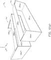
- FIG. 6(a) , FIG. 6(b) , FIG. 6(c) and FIG. 6(d) illustrate four non-limiting alternative examples of box-like moveable passive coil sections for controlling areas of flux coupling with a workpiece passing under and/or over the passive sections in order to achieve a required cross sectional temperature profile in the inductively heated workpiece.
- bridge section 14b 1 has a semicircular cutout (SCO) adjacent to one of its ends in the Y-direction, which assists in directing inductive heating flux coupling toward the ends of bridge section 14b 1 that are adjacent to side sections 14a 1 .
- SCO semicircular cutout
- bridge section 14b 2 has cutouts (CO) adjacent to one of its ends in the Y-direction, which assists in directing inductive heating flux coupling towards the center of bridge section 14b 2 and away from the bridge section regions adjacent to side sections 14a 2 .
- cutouts (CO) adjacent to one of its ends in the Y-direction, which assists in directing inductive heating flux coupling towards the center of bridge section 14b 2 and away from the bridge section regions adjacent to side sections 14a 2 .
- one (or more) slots (S) are cutout of bridge section 14b 3 , which enhances inductive heating flux coupling between the slotted regions of the bridge section.
- the box-like moveable coil section may comprise two or more separately moveable box-like coils as illustrated, for example, in FIG.
- Each coil may be electrically isolated from each other and independently slidably connected by mechanical connection to the end of a fixed planar coil section.
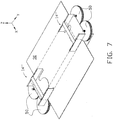
- Means can be provided to have the moveable passive coils sections move along with (track) the instantaneous positions of the edges of the workpiece.
- Non-limiting examples are sensing means that sense the instantaneous positions, or the temperature profile, of the edges of the workpiece in combination with passive coil section actuators that move the passive coil sections responsive to the output of the sensing means.
- laser beam sensors that sense the instantaneous position of the edges can output signals to a computer processing circuit that signals hydraulic actuators to move the passive coil sections accordingly.
- linear guides or rolls 50 may be utilized as shown, for example, in FIG. 7 . In FIG. 7 only moveable passive coil sections 14" ( FIG. 6(b) ) are shown and not the associated fixed powered coil section that spans the transverse of workpiece 90.
- Means may also be provided for adjustably moving the moveable passive coil sections in a direction (Z-direction) perpendicular to a surface of the workpiece.
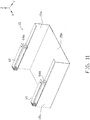
- FIG. 10 Another example of the variable width transverse flux electric induction coil of the present invention wherein magnetic coupling between the fixed powered coil section and a moveable passive coil section is replaced by one or more electrically conductive paths between the fixed and moveable coil sections that are maintained as the moveable coil sections are moved relative to the fixed coil section.
- the fixed powered coil section comprises riser sections 13a and leg sections 13b with moveable passive coil section 15, as best seen in FIG. 11 , comprising opposing side sections 15a joined by bridge section 15b.
- Each flexible electrical connection is shown in FIG. 10 and FIG.
- the flexible electrically conductive strips are but two examples of methods of maintaining an electrical connection between a fixed powered coil section and an adjacent moveable passive coil section.
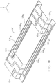
- FIG. 13(a) through FIG. 13(e) illustrate another example of the transverse flux electric induction coil assembly 30 of the present invention. Only a partial view of the coil is shown to illustrate the typical fixed powered coil section 32 in relation to box-like moveable passive coil section 34 at one end of the coil.
- the coil assembly is spatially oriented for use as an upper induction coil with the workpiece positioned below the coil assembly.
- each riser section 32c of fixed coil section 32 optionally extends over the entire length, L, of a transverse leg section 32b, and the box-like moveable passive coil section 34 comprises opposing side sections 34a joined by slat bridge section 34b, and section 34c, which connects opposing side sections 34a.
- Box-like moveable passive coil section 34 is slidably (by mechanical means) attached to fixed coil section 32, while being electrically isolated from it, and fits within the volume formed by bridge section 32a and riser sections 32c. In this arrangement magnetic flux generated around slat bridge section 34b couples with the workpiece to inductively heat the workpiece.
- FIG. 13(a) shows moveable passive coil section 34 fully retracted into the fixed coil section and
- FIG. 13(b) shows the moveable passive coil section fully extended from the fixed coil section.
- Moveable passive coil section 34 may also be used with any fixed powered coil section as previously described.
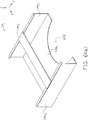
- FIG. 14(a) through FIG. 14(e) Another alternative example of the transverse flux electric induction coil assembly 30' of the present invention is illustrated in partial view in FIG. 14(a) through FIG. 14(e) .
- This example is similar to the example in FIG. 13(a) through FIG. 13(e) except that riser sections 32c' are angled off from the vertical (Z-axis) to form an acute angle with leg sections 32b'.
- box-like moveable passive coil section 34' has a trapezoidal shape.
- Moveable passive coil section 34' is slidably (by mechanical means) attached to fixed coil section 32' and fits within the volume formed by bridge section 32a' and riser sections 32c'.
- FIG. 14(a) shows moveable passive coil section 34' fully retracted into the fixed coil section
- FIG. 14(b) shows the moveable passive coil section fully extended from the fixed coil section.
- magnetic flux generated around slat bridge section 34b' couples with the workpiece to inductively heat the workpiece.
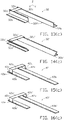
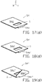
- FIG. 15(a) through FIG. 15(e) illustrate another example of the transverse flux electric induction coil assembly 40 of the present invention. Only a partial view of the coil is shown to illustrate the typical fixed powered coil section 42 in relation to box-like moveable passive coil section 44 at one end of the coil.
- the coil assembly is spatially oriented for use as an upper induction coil with the workpiece positioned below the coil assembly.
- each riser section 42c of fixed coil section 42 is connected to the opposing edge 42e of a leg section 42b on the side of each leg section facing away from the other leg section, as opposed to the example shown in FIG 1 where the riser section 12c of the fixed coil section is connected to edge 12f of a leg section 12b on the side of the leg facing towards the other leg section, and similarly in FIG. 13(c) where the riser section 32c of the fixed coil section is connected to edge 32f of a leg section 32b on the side of the leg facing towards the other leg section.
- Box-like moveable passive coil section 44 is slidably (by mechanical means) attached to fixed coil section 42, while being electrically isolated from it, and fits within the volume formed by bridge section 42a and riser sections 42c, with bridge section 44b seated substantially within the same plane as leg sections 42b.
- Bridge section 44b of the moveable passive section also includes sections 44b 1 and 44b 2 which are positioned over the ends of leg sections 42b.
- FIG. 15(a) shows moveable passive coil section 44 fully retracted into the fixed coil section and
- FIG. 15(b) shows the moveable passive coil section fully extended from the fixed coil section. In this arrangement magnetic flux generated around bridge section 44b couples with the workpiece to inductively heat the workpiece.
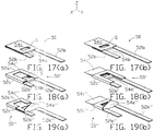
- FIG. 16(a) through FIG. 16(e) Another alternative example of the transverse flux electric induction coil assembly 40' of the present invention is illustrated in FIG. 16(a) through FIG. 16(e) .
- This example is similar to the example in FIG. 15(a) through FIG. 15(e) except that box-like moveable passive coil section 44' is slidably (by mechanical means) attached to fixed coil section 42' and fits over and around the volume formed by bridge section 42a', riser sections 42c', and leg sections 42b'.
- FIG. 16(a) shows moveable passive coil section 44' fully retracted into the fixed coil section
- FIG. 16(b) shows the moveable passive coil section fully extended from the fixed coil section.
- magnetic flux generated around "U" shaped bridge section 44b' couples with the workpiece to inductively heat the workpiece.
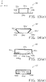
- FIG. 17(a) through FIG. 17(d) illustrate another example of the transverse flux electric induction coil assembly 50. Only a partial view of the coil is shown to illustrate the typical fixed powered coil section 52 in relation to box-like moveable passive coil section 54 at one end of the coil.
- the coil assembly is spatially oriented for use as an upper induction coil with the workpiece positioned below the coil assembly.
- bridge section 52a is connected directly to the opposing adjacent ends of the pair of leg sections 52b and is substantially co-planar with the pair of opposing leg sections.
- Box-like moveable passive coil section 54 is generally flat in shape with slat bridge section 54b seated substantially within the same plane as leg sections 52b and includes optional slat S.
- shape moveable passive coil section 54 represents a box-like shape wherein the height (Z-direction) of the box has degenerated to the flat shape shown in FIG. 17(d) .
- Passive coil section 54 is slidably (by mechanical means) attached to fixed coil section 52, while being electrically isolated from it, and slides over the bridge and leg sections comprising the fixed coil section.
- FIG. 17(a) shows moveable passive coil section 54 fully retracted into fixed coil section 52
- FIG. 17(b) shows the moveable passive coil section fully extended from the fixed coil section.
- FIG. 18(a) through FIG. 18(d) illustrate another example of the transverse flux electric induction coil assembly 50'. Only a partial view of the coil is shown to illustrate the typical fixed powered coil section 52' in relation to box-like moveable passive coil section 54' at one end of the coil.
- the coil assembly is spatially oriented for use as an upper induction coil with the workpiece positioned below the coil assembly.
- fixed coil section 52' comprises fixed coil section 52 in FIG. 17(d) in combination with riser sections 52c' and "U" shaped bridge section 52a'.
- Box-like moveable passive coil section 54' is similar to moveable passive coil section 54 shown in FIG. 17(c) .
- FIG. 19(a) through FIG. 19(d) Another alternative example of the transverse flux electric induction coil assembly 50" is illustrated in FIG. 19(a) through FIG. 19(d) .
- This example is similar to the example in FIG. 18(a) through FIG. 18(d) except that moveable coil section 54" has an additional feature, namely shield or flap section 52e" which is attached to the interior end of slat bridge section 54b" and oriented at an angle from legs 52b" of fixed powered coil section 52".
- a flap section can be combined with any of the other box-like moveable passive coil sections of the present invention.
- transverse flux coils illustrated in figure groups 13 through 19 above represent an upper induction coil with reference to a workpiece positioned below the coil.
- Box-like moveable coil sections are shown at one end of the coil assembly and the length of the leg sections are shown only in partial lengths to shown the detail at one end of the coil unless the coil is asymmetric in configuration as discussed above.
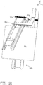
- FIG. 20 illustrates another example of a transverse flux electric induction coil of the present invention utilized in a gastight induction furnace application.
- An elongated electrically conductive workpiece can pass through substantially gastight enclosure 70.
- a pair of transverse flux electric induction coils of the present invention such as but not limited to coils 16a and 16b, are transversely located on the opposing exterior sides of the enclosure that are parallel to the plane of the workpiece.
- the gastight enclosure is formed from an electromagnetically transparent material at least in the regions where the alternating magnetic flux field can penetrate the enclosure and couple with the workpiece to inductively heat the workpiece.
- FIG. 21 illustrates another example of a transverse flux electric induction coil of the present invention.
- Each of a pair of transverse flux electric induction coils such as, but not limited to those shown in FIG. 3 , are attached at one transverse end to rotating apparatus 72a or 72b to rotate the transverse flux induction coil around an axis parallel to the movement of the workpiece. This arrangement is useful for accommodating cleaning of the insides (facing workpiece 90) of the coils.
- the workpiece and transverse flux induction coils are generally horizontal in orientation but this is not a limiting feature of the invention.
- the workpiece and transverse flux induction coils may be vertically oriented in a workpiece coating process where the workpiece passes vertically between a pair of flux induction coils to inductively heat the workpiece so that evaporative coating of the workpiece is achieved.
- each transverse flux induction coil comprises a fixed powered coil section and a pair of movcable passive coil sections.
- the transverse flux induction coil may comprise a fixed powered coil section and one moveable passive coil section located under a bridge of the fixed section at only one end of the fixed powered coil section.
Landscapes
- Physics & Mathematics (AREA)
- Electromagnetism (AREA)
- Engineering & Computer Science (AREA)
- Power Engineering (AREA)
- General Induction Heating (AREA)
Priority Applications (1)
| Application Number | Priority Date | Filing Date | Title |
|---|---|---|---|
| EP21161593.5A EP3852493A1 (en) | 2008-04-14 | 2009-04-14 | Variable width transverse flux electric induction coils |
Applications Claiming Priority (2)
| Application Number | Priority Date | Filing Date | Title |
|---|---|---|---|
| US4454508P | 2008-04-14 | 2008-04-14 | |
| PCT/US2009/040525 WO2009129239A2 (en) | 2008-04-14 | 2009-04-14 | Variable width transverse flux electric induction coils |
Related Child Applications (1)
| Application Number | Title | Priority Date | Filing Date |
|---|---|---|---|
| EP21161593.5A Division EP3852493A1 (en) | 2008-04-14 | 2009-04-14 | Variable width transverse flux electric induction coils |
Publications (3)
| Publication Number | Publication Date |
|---|---|
| EP2283496A2 EP2283496A2 (en) | 2011-02-16 |
| EP2283496A4 EP2283496A4 (en) | 2014-10-29 |
| EP2283496B1 true EP2283496B1 (en) | 2021-04-07 |
Family
ID=41163139
Family Applications (2)
| Application Number | Title | Priority Date | Filing Date |
|---|---|---|---|
| EP09731695.4A Active EP2283496B1 (en) | 2008-04-14 | 2009-04-14 | Variable width transverse flux electric induction coils |
| EP21161593.5A Withdrawn EP3852493A1 (en) | 2008-04-14 | 2009-04-14 | Variable width transverse flux electric induction coils |
Family Applications After (1)
| Application Number | Title | Priority Date | Filing Date |
|---|---|---|---|
| EP21161593.5A Withdrawn EP3852493A1 (en) | 2008-04-14 | 2009-04-14 | Variable width transverse flux electric induction coils |
Country Status (6)
| Country | Link |
|---|---|
| US (2) | US9445460B2 (OSRAM) |
| EP (2) | EP2283496B1 (OSRAM) |
| JP (1) | JP5352664B2 (OSRAM) |
| KR (1) | KR101576479B1 (OSRAM) |
| CN (1) | CN102067254B (OSRAM) |
| WO (1) | WO2009129239A2 (OSRAM) |
Families Citing this family (23)
| Publication number | Priority date | Publication date | Assignee | Title |
|---|---|---|---|---|
| US7973446B2 (en) * | 2007-05-09 | 2011-07-05 | Motor Excellence, Llc | Electrical devices having tape wound core laminate rotor or stator elements |
| WO2009129239A2 (en) * | 2008-04-14 | 2009-10-22 | Inductotherm Corp. | Variable width transverse flux electric induction coils |
| CN102227862A (zh) | 2008-11-03 | 2011-10-26 | 卓越发动机有限责任公司 | 多相横向和/或换向磁通系统 |
| PL2538749T3 (pl) * | 2010-02-19 | 2018-09-28 | Nippon Steel & Sumitomo Metal Corporation | Urządzenie do nagrzewania indukcyjnego w poprzecznym polu magnetycznym |
| EP2548287A1 (en) | 2010-03-15 | 2013-01-23 | Motor Excellence, LLC | Transverse and/or commutated flux system for electric bicycles |
| CN102959832B (zh) | 2010-03-15 | 2016-11-16 | 电扭矩机器股份有限公司 | 具有相偏移的横向和/或换向通量系统 |
| US8053944B2 (en) | 2010-03-15 | 2011-11-08 | Motor Excellence, Llc | Transverse and/or commutated flux systems configured to provide reduced flux leakage, hysteresis loss reduction, and phase matching |
| US8854171B2 (en) | 2010-11-17 | 2014-10-07 | Electric Torque Machines Inc. | Transverse and/or commutated flux system coil concepts |
| WO2012067893A2 (en) | 2010-11-17 | 2012-05-24 | Motor Excellence, Llc | Transverse and/or commutated flux systems having segmented stator laminations |
| US8952590B2 (en) | 2010-11-17 | 2015-02-10 | Electric Torque Machines Inc | Transverse and/or commutated flux systems having laminated and powdered metal portions |
| FR3014449B1 (fr) | 2013-12-06 | 2020-12-04 | Fives Celes | Section de recuit apres galvanisation comportant un appareil de chauffage a inducteur a flux transverse |
| WO2015094482A1 (en) * | 2013-12-20 | 2015-06-25 | Ajax Tocco Magnethermic Corporation | Transverse flux strip heating dc edge saturation |
| US10321524B2 (en) | 2014-01-17 | 2019-06-11 | Nike, Inc. | Conveyance curing system |
| RU2674250C2 (ru) * | 2014-09-05 | 2018-12-06 | Ниппон Стил Энд Сумитомо Метал Корпорейшн | Индукционное нагревательное устройство для металлической полосы |
| EP3016136B1 (en) * | 2014-10-27 | 2021-07-21 | Robert Bosch GmbH | Transport system with magnetically driven transport elements and according transportation method |
| KR101714869B1 (ko) * | 2015-04-16 | 2017-03-10 | 주식회사 피에스텍 | 유도 가열 장치용 코일 어셈블리 및 이를 포함하는 유도 가열 장치 |
| KR102094623B1 (ko) | 2015-06-24 | 2020-03-27 | 노벨리스 인크. | 금속 처리 퍼니스들과 조합하여 사용되는 고속 응답 히터들 및 연관된 제어 시스템들 |
| US10638553B2 (en) * | 2015-06-30 | 2020-04-28 | Danieli & C. Officine Meccaniche S.P.A. | Transverse flux induction heating apparatus |
| US10143044B1 (en) * | 2015-09-21 | 2018-11-27 | Inductotherm Corp. | Electric induction heating of strip or slab material |
| EP3580996B1 (en) * | 2017-02-08 | 2022-02-16 | Inductotherm Corp. | Adjustable transverse inductors for inductively heating strips or slabs |
| FR3107635B1 (fr) * | 2020-02-24 | 2023-06-02 | Fives Celes | Dispositif de chauffage d’un produit par induction a flux transverse |
| ES3050614T3 (en) * | 2020-07-15 | 2025-12-22 | Abp Induction Systems Gmbh | Method and system for inductively heating flat articles |
| CN115094220B (zh) * | 2022-07-11 | 2024-03-26 | 无锡德泉精密机械有限公司 | 一种铸件的回火处理装置及其制作工艺 |
Family Cites Families (14)
| Publication number | Priority date | Publication date | Assignee | Title |
|---|---|---|---|---|
| US4778971A (en) * | 1986-05-23 | 1988-10-18 | Kabushiki Kaisha Meidensha | Induction heating apparatus |
| JPH0349561A (ja) | 1989-07-14 | 1991-03-04 | Mitsubishi Heavy Ind Ltd | 合金化用誘導加熱における電源制御装置 |
| JPH04294091A (ja) | 1991-03-22 | 1992-10-19 | Mitsubishi Heavy Ind Ltd | 誘導加熱装置 |
| JPH061307A (ja) | 1992-06-17 | 1994-01-11 | Mihama Seisakusho:Kk | 締付けバンドの締付け機 |
| US5495094A (en) * | 1994-04-08 | 1996-02-27 | Inductotherm Corp. | Continuous strip material induction heating coil |
| JPH08165517A (ja) | 1994-12-09 | 1996-06-25 | Fuji Denshi Kogyo Kk | 高周波加熱装置 |
| JP2913615B2 (ja) * | 1994-12-09 | 1999-06-28 | 富士電子工業株式会社 | 絶縁部材およびこれを使用した高周波加熱装置 |
| GB9503390D0 (en) * | 1995-02-21 | 1995-04-12 | Davy Mckee Poole | "Variable-width induction heater |
| US6576878B2 (en) * | 2001-01-03 | 2003-06-10 | Inductotherm Corp. | Transverse flux induction heating apparatus |
| FR2821925B1 (fr) * | 2001-03-06 | 2003-05-16 | Celes | Enceinte d'etancheite au gaz et au vide d'isolation thermique destinee a un dispositif de chauffage par induction |
| US6570141B2 (en) | 2001-03-26 | 2003-05-27 | Nicholas V. Ross | Transverse flux induction heating of conductive strip |
| JP2009522816A (ja) * | 2006-01-09 | 2009-06-11 | インダクトサーム・コーポレイション | 電磁的にシールドした誘導加熱装置 |
| KR20080111093A (ko) * | 2006-03-29 | 2008-12-22 | 인덕터썸코포레이션 | 트랜스버스 플럭스 유도가열 장치 및 보상기 |
| WO2009129239A2 (en) * | 2008-04-14 | 2009-10-22 | Inductotherm Corp. | Variable width transverse flux electric induction coils |
-
2009
- 2009-04-14 WO PCT/US2009/040525 patent/WO2009129239A2/en not_active Ceased
- 2009-04-14 CN CN200980122349XA patent/CN102067254B/zh active Active
- 2009-04-14 EP EP09731695.4A patent/EP2283496B1/en active Active
- 2009-04-14 EP EP21161593.5A patent/EP3852493A1/en not_active Withdrawn
- 2009-04-14 US US12/423,418 patent/US9445460B2/en active Active
- 2009-04-14 KR KR1020107025415A patent/KR101576479B1/ko active Active
- 2009-04-14 JP JP2011505137A patent/JP5352664B2/ja active Active
-
2016
- 2016-09-11 US US15/261,974 patent/US9930730B2/en active Active
Non-Patent Citations (1)
| Title |
|---|
| None * |
Also Published As
| Publication number | Publication date |
|---|---|
| US9930730B2 (en) | 2018-03-27 |
| EP3852493A1 (en) | 2021-07-21 |
| WO2009129239A3 (en) | 2010-01-21 |
| CN102067254A (zh) | 2011-05-18 |
| JP2011517054A (ja) | 2011-05-26 |
| WO2009129239A2 (en) | 2009-10-22 |
| JP5352664B2 (ja) | 2013-11-27 |
| KR101576479B1 (ko) | 2015-12-10 |
| KR20100132549A (ko) | 2010-12-17 |
| EP2283496A2 (en) | 2011-02-16 |
| US9445460B2 (en) | 2016-09-13 |
| EP2283496A4 (en) | 2014-10-29 |
| US20090255924A1 (en) | 2009-10-15 |
| CN102067254B (zh) | 2013-09-25 |
| US20160381737A1 (en) | 2016-12-29 |
Similar Documents
| Publication | Publication Date | Title |
|---|---|---|
| EP2283496B1 (en) | Variable width transverse flux electric induction coils | |
| US7525073B2 (en) | Transverse flux electric inductors | |
| JP5450729B2 (ja) | 横断方向フラックス誘導加熱装置及び補償装置 | |
| AU778739B2 (en) | Transverse flux induction heating device with magnetic circuit of variable width | |
| KR101957069B1 (ko) | 금속 띠판의 유도 가열 장치 | |
| AU2009273793A1 (en) | Electric induction edge heating of electrically conductive slabs | |
| JP2025111831A (ja) | 平坦な製品を加熱するための横磁束誘導加熱装置 | |
| JP6331900B2 (ja) | 金属帯板の誘導加熱装置 | |
| TWM643995U (zh) | 橫向磁通感應線圈組配件 | |
| EA043812B1 (ru) | Устройство для индукционного нагрева с поперечным потоком для нагрева плоского изделия | |
| KR20200038518A (ko) | 양면 평면 인덕터 조립체 | |
| HK1129183A (en) | Transverse flux electric inductors | |
| WO2025153709A1 (en) | High power density induction heater |
Legal Events
| Date | Code | Title | Description |
|---|---|---|---|
| PUAI | Public reference made under article 153(3) epc to a published international application that has entered the european phase |
Free format text: ORIGINAL CODE: 0009012 |
|
| 17P | Request for examination filed |
Effective date: 20101110 |
|
| AK | Designated contracting states |
Kind code of ref document: A2 Designated state(s): AT BE BG CH CY CZ DE DK EE ES FI FR GB GR HR HU IE IS IT LI LT LU LV MC MK MT NL NO PL PT RO SE SI SK TR |
|
| AX | Request for extension of the european patent |
Extension state: AL BA RS |
|
| DAX | Request for extension of the european patent (deleted) | ||
| A4 | Supplementary search report drawn up and despatched |
Effective date: 20140930 |
|
| RIC1 | Information provided on ipc code assigned before grant |
Ipc: H01F 21/08 20060101ALI20140923BHEP Ipc: H01F 27/28 20060101AFI20140923BHEP |
|
| STAA | Information on the status of an ep patent application or granted ep patent |
Free format text: STATUS: EXAMINATION IS IN PROGRESS |
|
| 17Q | First examination report despatched |
Effective date: 20171128 |
|
| GRAP | Despatch of communication of intention to grant a patent |
Free format text: ORIGINAL CODE: EPIDOSNIGR1 |
|
| STAA | Information on the status of an ep patent application or granted ep patent |
Free format text: STATUS: GRANT OF PATENT IS INTENDED |
|
| INTG | Intention to grant announced |
Effective date: 20201102 |
|
| GRAS | Grant fee paid |
Free format text: ORIGINAL CODE: EPIDOSNIGR3 |
|
| GRAA | (expected) grant |
Free format text: ORIGINAL CODE: 0009210 |
|
| STAA | Information on the status of an ep patent application or granted ep patent |
Free format text: STATUS: THE PATENT HAS BEEN GRANTED |
|
| AK | Designated contracting states |
Kind code of ref document: B1 Designated state(s): AT BE BG CH CY CZ DE DK EE ES FI FR GB GR HR HU IE IS IT LI LT LU LV MC MK MT NL NO PL PT RO SE SI SK TR |
|
| REG | Reference to a national code |
Ref country code: GB Ref legal event code: FG4D |
|
| RIN1 | Information on inventor provided before grant (corrected) |
Inventor name: LOVENS, JEAN |
|
| REG | Reference to a national code |
Ref country code: AT Ref legal event code: REF Ref document number: 1380751 Country of ref document: AT Kind code of ref document: T Effective date: 20210415 Ref country code: CH Ref legal event code: EP |
|
| REG | Reference to a national code |
Ref country code: DE Ref legal event code: R096 Ref document number: 602009063548 Country of ref document: DE |
|
| REG | Reference to a national code |
Ref country code: IE Ref legal event code: FG4D |
|
| REG | Reference to a national code |
Ref country code: LT Ref legal event code: MG9D |
|
| REG | Reference to a national code |
Ref country code: NL Ref legal event code: MP Effective date: 20210407 Ref country code: AT Ref legal event code: MK05 Ref document number: 1380751 Country of ref document: AT Kind code of ref document: T Effective date: 20210407 |
|
| PG25 | Lapsed in a contracting state [announced via postgrant information from national office to epo] |
Ref country code: BG Free format text: LAPSE BECAUSE OF FAILURE TO SUBMIT A TRANSLATION OF THE DESCRIPTION OR TO PAY THE FEE WITHIN THE PRESCRIBED TIME-LIMIT Effective date: 20210707 Ref country code: AT Free format text: LAPSE BECAUSE OF FAILURE TO SUBMIT A TRANSLATION OF THE DESCRIPTION OR TO PAY THE FEE WITHIN THE PRESCRIBED TIME-LIMIT Effective date: 20210407 Ref country code: HR Free format text: LAPSE BECAUSE OF FAILURE TO SUBMIT A TRANSLATION OF THE DESCRIPTION OR TO PAY THE FEE WITHIN THE PRESCRIBED TIME-LIMIT Effective date: 20210407 Ref country code: LT Free format text: LAPSE BECAUSE OF FAILURE TO SUBMIT A TRANSLATION OF THE DESCRIPTION OR TO PAY THE FEE WITHIN THE PRESCRIBED TIME-LIMIT Effective date: 20210407 Ref country code: NL Free format text: LAPSE BECAUSE OF FAILURE TO SUBMIT A TRANSLATION OF THE DESCRIPTION OR TO PAY THE FEE WITHIN THE PRESCRIBED TIME-LIMIT Effective date: 20210407 Ref country code: FI Free format text: LAPSE BECAUSE OF FAILURE TO SUBMIT A TRANSLATION OF THE DESCRIPTION OR TO PAY THE FEE WITHIN THE PRESCRIBED TIME-LIMIT Effective date: 20210407 |
|
| PG25 | Lapsed in a contracting state [announced via postgrant information from national office to epo] |
Ref country code: SE Free format text: LAPSE BECAUSE OF FAILURE TO SUBMIT A TRANSLATION OF THE DESCRIPTION OR TO PAY THE FEE WITHIN THE PRESCRIBED TIME-LIMIT Effective date: 20210407 Ref country code: IS Free format text: LAPSE BECAUSE OF FAILURE TO SUBMIT A TRANSLATION OF THE DESCRIPTION OR TO PAY THE FEE WITHIN THE PRESCRIBED TIME-LIMIT Effective date: 20210807 Ref country code: LV Free format text: LAPSE BECAUSE OF FAILURE TO SUBMIT A TRANSLATION OF THE DESCRIPTION OR TO PAY THE FEE WITHIN THE PRESCRIBED TIME-LIMIT Effective date: 20210407 Ref country code: GR Free format text: LAPSE BECAUSE OF FAILURE TO SUBMIT A TRANSLATION OF THE DESCRIPTION OR TO PAY THE FEE WITHIN THE PRESCRIBED TIME-LIMIT Effective date: 20210708 Ref country code: NO Free format text: LAPSE BECAUSE OF FAILURE TO SUBMIT A TRANSLATION OF THE DESCRIPTION OR TO PAY THE FEE WITHIN THE PRESCRIBED TIME-LIMIT Effective date: 20210707 Ref country code: PL Free format text: LAPSE BECAUSE OF FAILURE TO SUBMIT A TRANSLATION OF THE DESCRIPTION OR TO PAY THE FEE WITHIN THE PRESCRIBED TIME-LIMIT Effective date: 20210407 Ref country code: PT Free format text: LAPSE BECAUSE OF FAILURE TO SUBMIT A TRANSLATION OF THE DESCRIPTION OR TO PAY THE FEE WITHIN THE PRESCRIBED TIME-LIMIT Effective date: 20210809 Ref country code: ES Free format text: LAPSE BECAUSE OF FAILURE TO SUBMIT A TRANSLATION OF THE DESCRIPTION OR TO PAY THE FEE WITHIN THE PRESCRIBED TIME-LIMIT Effective date: 20210407 |
|
| REG | Reference to a national code |
Ref country code: DE Ref legal event code: R097 Ref document number: 602009063548 Country of ref document: DE |
|
| PG25 | Lapsed in a contracting state [announced via postgrant information from national office to epo] |
Ref country code: SK Free format text: LAPSE BECAUSE OF FAILURE TO SUBMIT A TRANSLATION OF THE DESCRIPTION OR TO PAY THE FEE WITHIN THE PRESCRIBED TIME-LIMIT Effective date: 20210407 Ref country code: EE Free format text: LAPSE BECAUSE OF FAILURE TO SUBMIT A TRANSLATION OF THE DESCRIPTION OR TO PAY THE FEE WITHIN THE PRESCRIBED TIME-LIMIT Effective date: 20210407 Ref country code: CZ Free format text: LAPSE BECAUSE OF FAILURE TO SUBMIT A TRANSLATION OF THE DESCRIPTION OR TO PAY THE FEE WITHIN THE PRESCRIBED TIME-LIMIT Effective date: 20210407 Ref country code: DK Free format text: LAPSE BECAUSE OF FAILURE TO SUBMIT A TRANSLATION OF THE DESCRIPTION OR TO PAY THE FEE WITHIN THE PRESCRIBED TIME-LIMIT Effective date: 20210407 Ref country code: RO Free format text: LAPSE BECAUSE OF FAILURE TO SUBMIT A TRANSLATION OF THE DESCRIPTION OR TO PAY THE FEE WITHIN THE PRESCRIBED TIME-LIMIT Effective date: 20210407 Ref country code: CH Free format text: LAPSE BECAUSE OF NON-PAYMENT OF DUE FEES Effective date: 20210430 Ref country code: LI Free format text: LAPSE BECAUSE OF NON-PAYMENT OF DUE FEES Effective date: 20210430 Ref country code: MC Free format text: LAPSE BECAUSE OF FAILURE TO SUBMIT A TRANSLATION OF THE DESCRIPTION OR TO PAY THE FEE WITHIN THE PRESCRIBED TIME-LIMIT Effective date: 20210407 |
|
| PLBE | No opposition filed within time limit |
Free format text: ORIGINAL CODE: 0009261 |
|
| STAA | Information on the status of an ep patent application or granted ep patent |
Free format text: STATUS: NO OPPOSITION FILED WITHIN TIME LIMIT |
|
| 26N | No opposition filed |
Effective date: 20220110 |
|
| PG25 | Lapsed in a contracting state [announced via postgrant information from national office to epo] |
Ref country code: IE Free format text: LAPSE BECAUSE OF NON-PAYMENT OF DUE FEES Effective date: 20210414 |
|
| PG25 | Lapsed in a contracting state [announced via postgrant information from national office to epo] |
Ref country code: IS Free format text: LAPSE BECAUSE OF FAILURE TO SUBMIT A TRANSLATION OF THE DESCRIPTION OR TO PAY THE FEE WITHIN THE PRESCRIBED TIME-LIMIT Effective date: 20210807 |
|
| PG25 | Lapsed in a contracting state [announced via postgrant information from national office to epo] |
Ref country code: IT Free format text: LAPSE BECAUSE OF FAILURE TO SUBMIT A TRANSLATION OF THE DESCRIPTION OR TO PAY THE FEE WITHIN THE PRESCRIBED TIME-LIMIT Effective date: 20210407 |
|
| PG25 | Lapsed in a contracting state [announced via postgrant information from national office to epo] |
Ref country code: HU Free format text: LAPSE BECAUSE OF FAILURE TO SUBMIT A TRANSLATION OF THE DESCRIPTION OR TO PAY THE FEE WITHIN THE PRESCRIBED TIME-LIMIT; INVALID AB INITIO Effective date: 20090414 Ref country code: CY Free format text: LAPSE BECAUSE OF FAILURE TO SUBMIT A TRANSLATION OF THE DESCRIPTION OR TO PAY THE FEE WITHIN THE PRESCRIBED TIME-LIMIT Effective date: 20210407 |
|
| PG25 | Lapsed in a contracting state [announced via postgrant information from national office to epo] |
Ref country code: MK Free format text: LAPSE BECAUSE OF FAILURE TO SUBMIT A TRANSLATION OF THE DESCRIPTION OR TO PAY THE FEE WITHIN THE PRESCRIBED TIME-LIMIT Effective date: 20210407 |
|
| PG25 | Lapsed in a contracting state [announced via postgrant information from national office to epo] |
Ref country code: TR Free format text: LAPSE BECAUSE OF FAILURE TO SUBMIT A TRANSLATION OF THE DESCRIPTION OR TO PAY THE FEE WITHIN THE PRESCRIBED TIME-LIMIT Effective date: 20210407 |
|
| PG25 | Lapsed in a contracting state [announced via postgrant information from national office to epo] |
Ref country code: MT Free format text: LAPSE BECAUSE OF FAILURE TO SUBMIT A TRANSLATION OF THE DESCRIPTION OR TO PAY THE FEE WITHIN THE PRESCRIBED TIME-LIMIT Effective date: 20210407 |
|
| PGFP | Annual fee paid to national office [announced via postgrant information from national office to epo] |
Ref country code: LU Payment date: 20250326 Year of fee payment: 17 |
|
| PGFP | Annual fee paid to national office [announced via postgrant information from national office to epo] |
Ref country code: BE Payment date: 20250318 Year of fee payment: 17 |
|
| PGFP | Annual fee paid to national office [announced via postgrant information from national office to epo] |
Ref country code: FR Payment date: 20250210 Year of fee payment: 17 |
|
| PGFP | Annual fee paid to national office [announced via postgrant information from national office to epo] |
Ref country code: GB Payment date: 20250220 Year of fee payment: 17 |
|
| PGFP | Annual fee paid to national office [announced via postgrant information from national office to epo] |
Ref country code: DE Payment date: 20250218 Year of fee payment: 17 |