EP2282141A2 - In-roof solar collector fitting assembly - Google Patents
In-roof solar collector fitting assembly Download PDFInfo
- Publication number
- EP2282141A2 EP2282141A2 EP10165521A EP10165521A EP2282141A2 EP 2282141 A2 EP2282141 A2 EP 2282141A2 EP 10165521 A EP10165521 A EP 10165521A EP 10165521 A EP10165521 A EP 10165521A EP 2282141 A2 EP2282141 A2 EP 2282141A2
- Authority
- EP
- European Patent Office
- Prior art keywords
- profiles
- profile
- arrangement according
- legs
- gutter system
- Prior art date
- Legal status (The legal status is an assumption and is not a legal conclusion. Google has not performed a legal analysis and makes no representation as to the accuracy of the status listed.)
- Withdrawn
Links
- 238000009434 installation Methods 0.000 claims description 3
- 239000007788 liquid Substances 0.000 description 4
- 230000000295 complement effect Effects 0.000 description 3
- 230000000694 effects Effects 0.000 description 3
- 239000000463 material Substances 0.000 description 2
- 210000001331 nose Anatomy 0.000 description 2
- 238000007789 sealing Methods 0.000 description 2
- XLYOFNOQVPJJNP-UHFFFAOYSA-N water Substances O XLYOFNOQVPJJNP-UHFFFAOYSA-N 0.000 description 2
- 229910000806 Latten Inorganic materials 0.000 description 1
- 238000010521 absorption reaction Methods 0.000 description 1
- 238000005452 bending Methods 0.000 description 1
- 238000005253 cladding Methods 0.000 description 1
- 238000010276 construction Methods 0.000 description 1
- 230000001419 dependent effect Effects 0.000 description 1
- 238000011161 development Methods 0.000 description 1
- 230000018109 developmental process Effects 0.000 description 1
- 239000002184 metal Substances 0.000 description 1
- 238000012986 modification Methods 0.000 description 1
- 230000004048 modification Effects 0.000 description 1
Images


Classifications
-
- E—FIXED CONSTRUCTIONS
- E04—BUILDING
- E04D—ROOF COVERINGS; SKY-LIGHTS; GUTTERS; ROOF-WORKING TOOLS
- E04D13/00—Special arrangements or devices in connection with roof coverings; Protection against birds; Roof drainage; Sky-lights
- E04D13/04—Roof drainage; Drainage fittings in flat roofs, balconies or the like
- E04D13/0404—Drainage on the roof surface
- E04D13/0445—Drainage channels
-
- F—MECHANICAL ENGINEERING; LIGHTING; HEATING; WEAPONS; BLASTING
- F24—HEATING; RANGES; VENTILATING
- F24S—SOLAR HEAT COLLECTORS; SOLAR HEAT SYSTEMS
- F24S25/00—Arrangement of stationary mountings or supports for solar heat collector modules
- F24S25/30—Arrangement of stationary mountings or supports for solar heat collector modules using elongate rigid mounting elements extending substantially along the supporting surface, e.g. for covering buildings with solar heat collectors
- F24S25/33—Arrangement of stationary mountings or supports for solar heat collector modules using elongate rigid mounting elements extending substantially along the supporting surface, e.g. for covering buildings with solar heat collectors forming substantially planar assemblies, e.g. of coplanar or stacked profiles
-
- F—MECHANICAL ENGINEERING; LIGHTING; HEATING; WEAPONS; BLASTING
- F24—HEATING; RANGES; VENTILATING
- F24S—SOLAR HEAT COLLECTORS; SOLAR HEAT SYSTEMS
- F24S40/00—Safety or protection arrangements of solar heat collectors; Preventing malfunction of solar heat collectors
- F24S40/40—Preventing corrosion; Protecting against dirt or contamination
- F24S40/44—Draining rainwater or condensation
-
- H—ELECTRICITY
- H02—GENERATION; CONVERSION OR DISTRIBUTION OF ELECTRIC POWER
- H02S—GENERATION OF ELECTRIC POWER BY CONVERSION OF INFRARED RADIATION, VISIBLE LIGHT OR ULTRAVIOLET LIGHT, e.g. USING PHOTOVOLTAIC [PV] MODULES
- H02S20/00—Supporting structures for PV modules
- H02S20/20—Supporting structures directly fixed to an immovable object
- H02S20/22—Supporting structures directly fixed to an immovable object specially adapted for buildings
- H02S20/23—Supporting structures directly fixed to an immovable object specially adapted for buildings specially adapted for roof structures
-
- Y—GENERAL TAGGING OF NEW TECHNOLOGICAL DEVELOPMENTS; GENERAL TAGGING OF CROSS-SECTIONAL TECHNOLOGIES SPANNING OVER SEVERAL SECTIONS OF THE IPC; TECHNICAL SUBJECTS COVERED BY FORMER USPC CROSS-REFERENCE ART COLLECTIONS [XRACs] AND DIGESTS
- Y02—TECHNOLOGIES OR APPLICATIONS FOR MITIGATION OR ADAPTATION AGAINST CLIMATE CHANGE
- Y02B—CLIMATE CHANGE MITIGATION TECHNOLOGIES RELATED TO BUILDINGS, e.g. HOUSING, HOUSE APPLIANCES OR RELATED END-USER APPLICATIONS
- Y02B10/00—Integration of renewable energy sources in buildings
- Y02B10/10—Photovoltaic [PV]
-
- Y—GENERAL TAGGING OF NEW TECHNOLOGICAL DEVELOPMENTS; GENERAL TAGGING OF CROSS-SECTIONAL TECHNOLOGIES SPANNING OVER SEVERAL SECTIONS OF THE IPC; TECHNICAL SUBJECTS COVERED BY FORMER USPC CROSS-REFERENCE ART COLLECTIONS [XRACs] AND DIGESTS
- Y02—TECHNOLOGIES OR APPLICATIONS FOR MITIGATION OR ADAPTATION AGAINST CLIMATE CHANGE
- Y02B—CLIMATE CHANGE MITIGATION TECHNOLOGIES RELATED TO BUILDINGS, e.g. HOUSING, HOUSE APPLIANCES OR RELATED END-USER APPLICATIONS
- Y02B10/00—Integration of renewable energy sources in buildings
- Y02B10/20—Solar thermal
-
- Y—GENERAL TAGGING OF NEW TECHNOLOGICAL DEVELOPMENTS; GENERAL TAGGING OF CROSS-SECTIONAL TECHNOLOGIES SPANNING OVER SEVERAL SECTIONS OF THE IPC; TECHNICAL SUBJECTS COVERED BY FORMER USPC CROSS-REFERENCE ART COLLECTIONS [XRACs] AND DIGESTS
- Y02—TECHNOLOGIES OR APPLICATIONS FOR MITIGATION OR ADAPTATION AGAINST CLIMATE CHANGE
- Y02E—REDUCTION OF GREENHOUSE GAS [GHG] EMISSIONS, RELATED TO ENERGY GENERATION, TRANSMISSION OR DISTRIBUTION
- Y02E10/00—Energy generation through renewable energy sources
- Y02E10/40—Solar thermal energy, e.g. solar towers
- Y02E10/47—Mountings or tracking
-
- Y—GENERAL TAGGING OF NEW TECHNOLOGICAL DEVELOPMENTS; GENERAL TAGGING OF CROSS-SECTIONAL TECHNOLOGIES SPANNING OVER SEVERAL SECTIONS OF THE IPC; TECHNICAL SUBJECTS COVERED BY FORMER USPC CROSS-REFERENCE ART COLLECTIONS [XRACs] AND DIGESTS
- Y02—TECHNOLOGIES OR APPLICATIONS FOR MITIGATION OR ADAPTATION AGAINST CLIMATE CHANGE
- Y02E—REDUCTION OF GREENHOUSE GAS [GHG] EMISSIONS, RELATED TO ENERGY GENERATION, TRANSMISSION OR DISTRIBUTION
- Y02E10/00—Energy generation through renewable energy sources
- Y02E10/50—Photovoltaic [PV] energy
Definitions
- the invention relates to an in-roof solar collector mounting arrangement comprising a multiplicity of planar solar modules which can be mounted on mounting rails, gap-like spacing spaces remaining between the solar modules, according to the preamble of patent claim 1.
- the invention is based on an in-roof solar collector mounting arrangement, which comprises a plurality of planar solar modules that can be mounted on mounting rails. Between the solar modules remain fixing and execution conditional gap-like distance spaces.
- a gutter system is formed below the solar collector arrangement, which covers at least the gap-like spacing spaces, and furthermore wherein the gutter system has a liquid-guiding orientation and a corresponding gradient.
- the channel system consists of intersecting profiles, wherein a node profile or a gusset plate is located in the crossing region, which receives the respective profile ends, so that collected liquid can be derived.
- the mounting rails for mounting the solar modules are preferably arranged extending within the gutter system.
- the gutter system may include U- or C-shaped flat profiles that collide at the intersections resulting from the solar collector mounting assembly.
- the node profile has two parallel legs in the direction of fall and two funnel legs at an angle to the direction of the fall, wherein the clear distance of the parallel legs is matched to the profile dimensions of the gutter system.
- Ausgestaltend rich the funnel legs with their pointing in the direction of slope ends in the Profiilraum the respective profile of the gutter system, so that this way a secure management of moisture, especially rainwater, for the purpose of dissipation is possible.
- the node profile has two opposite, adjacent to the funnel legs bends or bends, which right and left side have a different height on.
- the gutter system basically has longitudinal and transverse profiles.
- profiles can, as already mentioned in the introduction, be designed as drip or channel plates.
- the material of the profiles can be plastic or corrosion-protected metal, preference being given to a plastic material in view of possible negative dew point effects.
- the extending in the direction of slope legs of the profiles engage behind at least partially the underside of the respective solar modules in order to improve the sealing effect and to prevent the ingress of moisture, especially in driving rain.
- the direction of fall corresponds to the longitudinal direction of the arrangement, wherein the transversely extending profiles have legs with a leg height which is smaller than the leg height of the profiles in the longitudinal direction.
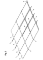
- Fig. 1 the arrangement according to the invention in the direction of slope, parallel oriented mounting rails 1.
- These mounting rails are executable as a C-profile and each serve the load-removing fixation of a corresponding edge of the solar module 2 (see Fig. 4 ).
- the gutter system according to the invention is used.
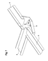
- This gutter system comprises in gradient, ie longitudinally extending first profile 4 and transversely extending second profiles 5. At crossing points, as in Fig. 2 shown, a node profile 6 is located, which receives the respective ends of the profiles 4 and 5. The node profile 6 is formed so that the profiles 4, 5 are variably displaceable for length compensation.
- the mounting rails 1 can run within the channel system, in particular within the profile 4 and the node profile 6.
- the profiles 4 and 5 are formed as U- or C-shaped flat profiles, which, as stated, collide at the intersection points resulting from the solar collector mounting arrangement.
- the node profile 6 has in the direction of fall two parallel legs 7 and 8, which extend in the direction of the legs of the profiles 4 and 5 respectively.
- the node profile has 6 funnel legs 9 and 10.
- the clear distance of the parallel legs 7 and 8 is on the profile dimensions of the gutter system, as in Fig. 2 visible, agreed.
- the funnel legs 9 and 10 receive amounts of liquid in the direction of fall and lead them from the profiles 5 and / or the profile 4 located above the direction of fall over in a deeper lying in the direction of fall profile 4, and ultimately to a drain device, not shown.
- the funnel legs 9 and 10 extend into the profile space of the respective profile 4 of the gutter system in order to effectively prevent system leaks.
- the node profile 6 has two opposite, adjacent to the funnel legs 9 and 10 bends 11 or corresponding bends.
- the bends 11 or folds are each engaged behind by a profile end of the gutter system.
- the aforementioned engaging behind the profile ends of the profiles 5 is on the relevant edge 5.1 at the respective end of the profile 5 after Fig. 4 made aware.
- the height of the legs of the profiles 4 is formed larger in the example shown than the height of the corresponding legs of the profiles 5. There is the possibility of underside hitting relative to the corresponding solar module 2 to improve the sealing effect, especially in rain blow.
- Fig. 6 is assumed by a node profile 6, which left-sided Aufkantitch or bends 11.1 and right-sided bends or Aufkantitch 11.2 respectively.
- the upstand In the example shown, 11.1 is higher than the one on the right-hand side (11.2), designed to ensure improved drainage in the case of flat roof inclines.
- a plurality of locking lugs 12 are provided in a portion of the node profile 6, the shape of which is complementary to corresponding lugs 13 at the ends of the corresponding profiles 4 (see Fig. 8 ). As a result, a form fit is given on the assembly side.
- the Fig. 7 indicates how the second profiles 5, which may have a different profile width, are introduced into the node profile. In this embodiment is due to the upstands 11.1 and 11.2 (see Fig. 6 ) engaging behind the profile ends not absolutely necessary, as has been described in the previous embodiment.
- Fig. 8 shows a perspective view of the profiles 4 and 5 on the one hand with the profile 4 located complementary noses 13 and on the other hand with a recognizable perforation line 14, which makes it possible to bend tab sections 15 depending on Montagagenbestwendtechnik to ensure attachment to roof battens.
- the tabs can serve as a stop, which further simplifies assembly.
- the perforation 14 is according to Fig. 9 For example, designed as a narrow longitudinal punch slot, wherein the width of the tabs 15 is selected so that a corresponding bending can be made without tools if necessary.
- the length of the legs 7 and 8 of the node profile 6 is chosen so that profiles 4 can be longitudinally displaceable and thus variably added to the length compensation.
- a length compensation is also related to the profiles 5, like the Fig. 7 shows, to some extent possible.
- the proposed gutter system consists of only three standard components, namely first, longer profiles 4, second, shorter profiles 5 and the node profile 6.
- the profile dimensions themselves are chosen so that rectangular solar modules can be mounted both with its longitudinal axis horizontally and vertically.
- the first and second profiles may become variable slidably received, so that different module sizes can be used during assembly to obtain a complex photovoltaic array.
- the arrangement of the individual components of the gutter system is able to absorb rainwater or the like liquids and safely divert from the quasi-open roof area. If desired, the elements of the channel system can still be connected cohesively and / or non-positively.
Abstract
Description
Die Erfindung betrifft eine Indach-Solarkollektormontageanordnung, umfassend eine Vielzahl von auf Tragschienen montierbaren flächigen Solarmodulen, wobei zwischen den Solarmodulen spaltartige Abstandsräume verbleiben, gemäß Oberbegriff des Patentanspruchs 1.The invention relates to an in-roof solar collector mounting arrangement comprising a multiplicity of planar solar modules which can be mounted on mounting rails, gap-like spacing spaces remaining between the solar modules, according to the preamble of patent claim 1.
Aus dem deutschen Gebrauchsmuster
Bei der Solarmodul- und Solarkollektormontageanordnung nach der
Die geschilderten Lösungen des Standes der Technik haben den Nachteil, dass trotz der vorgesehenen Indach-Montage von Solarkollektoren die Aussparung im Dach zu unterspannen ist mit der Folge einer sich insgesamt vergrößernden, abzutragenden Masse sowie eines erhöhten Montageaufwands.The described solutions of the prior art have the disadvantage that, in spite of the proposed in-roof mounting of solar collectors, the recess in the roof is to be underlaid with the result of a total magnifying, ablated mass and increased assembly costs.
Aus dem Vorgenannten ist es daher Aufgabe der Erfindung, eine weiterentwickelte Indach-Solarkollektormontageanordnung, umfassend eine Vielzahl von auf Tragschienen montierbaren flächigen Solarmodulen anzugeben, wobei die Möglichkeit besteht, auf ansonsten notwendige Unterspannungen, die vollflächig auszuführen sind, zu verzichten.From the foregoing, it is therefore an object of the invention to provide a further developed in-roof solar collector mounting arrangement, comprising a plurality of surface mountable on mounting rails solar modules, with the possibility to dispense with otherwise necessary undervoltages that are to perform over the entire surface.
Die Lösung der Aufgabe der Erfindung erfolgt durch eine Indach-Solarkollektormontageanordnung gemäß der Merkmalskombination nach Patentanspruch 1, wobei die Unteransprüche mindestens zweckmäßige Ausgestaltungen und Weiterbildungen umfassen.The object of the invention is achieved by an in-roof solar collector mounting arrangement according to the combination of features according to claim 1, wherein the dependent claims comprise at least expedient refinements and developments.
Erfindungsgemäß wird von einer Indach-Solarkollektormontageanordnung ausgegangen, welche eine Vielzahl von auf Tragschienen montierbaren flächigen Solarmodulen umfasst. Zwischen den Solarmodulen verbleiben befestigungs- und ausführungsbedingt spaltartige Abstandsräume.The invention is based on an in-roof solar collector mounting arrangement, which comprises a plurality of planar solar modules that can be mounted on mounting rails. Between the solar modules remain fixing and execution conditional gap-like distance spaces.
Erfindungsgemäß ist unterhalb der Solarkollektoranordnung ein Rinnensystem ausgebildet, welches mindestens die spaltartigen Abstandsräume unterdeckt und wobei weiterhin das Rinnensystem eine flüssigkeitsführende Orientierung und ein entsprechendes Gefälle aufweist.According to the invention, a gutter system is formed below the solar collector arrangement, which covers at least the gap-like spacing spaces, and furthermore wherein the gutter system has a liquid-guiding orientation and a corresponding gradient.
Bei einer bevorzugten Ausgestaltung der Erfindung besteht das Rinnensystem aus sich kreuzenden Profilen, wobei im Kreuzungsbereich ein Knotenprofil oder ein Knotenblech befindlich ist, welches die jeweiligen Profilenden aufnimmt, so dass aufgefangene Flüssigkeit abgeleitet werden kann.In a preferred embodiment of the invention, the channel system consists of intersecting profiles, wherein a node profile or a gusset plate is located in the crossing region, which receives the respective profile ends, so that collected liquid can be derived.
Die Tragschienen zur Montage der Solarmodule sind bevorzugt innerhalb des Rinnensystems verlaufend angeordnet.The mounting rails for mounting the solar modules are preferably arranged extending within the gutter system.
Das Rinnensystem kann U- oder C-förmige Flachprofile umfassen, die an den durch die Solarkollektormontageanordnung sich ergebenden Kreuzungspunkten zusammenstoßen.The gutter system may include U- or C-shaped flat profiles that collide at the intersections resulting from the solar collector mounting assembly.
Bei einer bevorzugten Ausgestaltung besitzt das Knotenprofiil in Gefällerichtung zwei parallel verlaufende Schenkel sowie winklig zur Gefällerichtung zwei Trichterschenkel, wobei der lichte Abstand der parallelen Schenkel auf die Profilmaße des Rinnensystems abgestimmt ist.In a preferred embodiment, the node profile has two parallel legs in the direction of fall and two funnel legs at an angle to the direction of the fall, wherein the clear distance of the parallel legs is matched to the profile dimensions of the gutter system.
Ausgestaltend reichen die Trichterschenkel mit ihren in Gefällerichtung weisenden Enden in den Profiilraum des jeweiligen Profils des Rinnensystems hinein, so dass auch hierdurch eine sichere Führung von Feuchtigkeit, insbesondere Regenwasser, zum Zweck des Ableitens möglich ist.Ausgestaltend rich the funnel legs with their pointing in the direction of slope ends in the Profiilraum the respective profile of the gutter system, so that this way a secure management of moisture, especially rainwater, for the purpose of dissipation is possible.
Weiterhin ausgestaltend weist das Knotenprofil zwei gegenüberliegende, an die Trichterschenkel angrenzende Abwinklungen oder Abkantungen, welche rechts- und linksseitig eine unterschiedliche Höhe besitzen, auf.Further ausgestaltend, the node profile has two opposite, adjacent to the funnel legs bends or bends, which right and left side have a different height on.
Diese Abwinklungen oder Abkantungen werden dann von jeweils einem Profilende des Rinnensystems hintergriffen. Letztgenannte Maßnahme schließt aus, dass adhäsionsbedingt Wassertropfen an der Unterseite des jeweiligen Profils entlanglaufen und womöglich in den freien Dachraum hinein abtropfen.These bends or bevels are then engaged behind by one profile end of the gutter system. The latter measure rules out that due to adhesion water droplets run along the underside of the respective profile and possibly drip into the free roof space.
Das Rinnensystem weist grundsätzlich längs und quer verlaufende Profile auf.The gutter system basically has longitudinal and transverse profiles.
Diese Profile können, wie bereits einleitend erwähnt, als Tropf- oder Rinnenbleche ausgebildet werden, Das Material der Profile kann Kunststoff oder korrosionsgeschütztes Metall sein, wobei unter dem Aspekt möglicher negativer Taupunkteffekte einem Kunststoffmaterial der Vorzug zu geben ist.These profiles can, as already mentioned in the introduction, be designed as drip or channel plates. The material of the profiles can be plastic or corrosion-protected metal, preference being given to a plastic material in view of possible negative dew point effects.
Die in Gefällerichtung verlaufenden Schenkel der Profile hintergreifen mindestens teilweise die Unterseite der jeweiligen Solarmodule, um die Dichtwirkung zu verbessern und das Eindringen von Feuchtigkeit insbesondere bei Schlagregen zu vermeiden.The extending in the direction of slope legs of the profiles engage behind at least partially the underside of the respective solar modules in order to improve the sealing effect and to prevent the ingress of moisture, especially in driving rain.
Die Gefällerichtung entspricht bei einer Ausgestaltung der Erfindung der Längsrichtung der Anordnung, wobei die in Querrichtung verlaufenden Profile Schenkel mit einer Schenkelhöhe aufweisen, die kleiner ist als die Schenkelhöhe der Profile in Längsrichtung.In one embodiment of the invention, the direction of fall corresponds to the longitudinal direction of the arrangement, wherein the transversely extending profiles have legs with a leg height which is smaller than the leg height of the profiles in the longitudinal direction.
Erfindungsgemäß ist darüber hinaus ein Rinnensystem zur Verwendung bei der Erstellung einer Indach-Solarkollektormontageanordnung.Moreover, according to the invention, there is a gutter system for use in the construction of an in-roof solar panel mounting arrangement.
Die Erfindung soll nachstehend anhand von Ausführungsbeispielen sowie unter Zuhilfenahme von Figuren näher erläutert werden.The invention will be explained below with reference to exemplary embodiments and with the aid of figures.
Hierbei zeigen:
- Fig. 1
- eine perspektivische Darstellung des teilweise bereits ausgeführten Rinnensystems mit Tragschienen für die noch nicht montierten Solar- module;
- Fig. 2
- eine Detaildarstellung A mit erkennbarem Knotenprofil im Kreuzungs- bereich der Profile des Rinnensystems;
- Fig. 3
- eine Darstellung der Ausführung des Rinnensystems mit teilweise mon- tierten flächigen Solarmodulen;
- Fig. 4
- eine Detaildarstellung des Rinnensystems mit einer Ecke eines Solar- moduls, seitlich fixiert von der Tragschiene;
- Fig. 5
- eine komplett mit Solarmodulen versehene Ausbildung als Indach- Anordnung;
- Fig. 6
- eine perspektivische Detaildarstellung des Knotenprofils mit erkennba- rer linksseitiger und rechtsseitiger, höhenmäßig unterschiedlich aus- gebildeter Aufkantung sowie Rastnasen zur vereinfachten Montage;
- Fig. 7
- eine Darstellung ähnlich derjenigen nach
Fig. 6 , jedoch mit bereits eingelegten zweiten Profilen mit unterschiedlicher Profilstruktur (Pro- filbreite) zum verbesserten Wasserablauf; - Fig. 8
- Detaildarstellungen der
Profile 4 und 5 mit an einer Perforation ab- kantbaren Laschen zur vereinfachten Befestigung der Profile an Dach- latten und - Fig. 9
- eine Detaildarstellung des ersten Profils mit Perforation und einzelnen Laschenabschnitten.
- Fig. 1
- a perspective view of the partially already executed gutter system with mounting rails for the not yet mounted solar modules;
- Fig. 2
- a detailed representation A with recognizable node profile in the crossing region of the profiles of the gutter system;
- Fig. 3
- a representation of the execution of the gutter system with partially mounted flat solar modules;
- Fig. 4
- a detailed representation of the gutter system with a corner of a solar module, laterally fixed by the mounting rail;
- Fig. 5
- a complete solar module training as in-roof arrangement;
- Fig. 6
- a detailed perspective view of the node profile with recognizable left-sided and right-sided, height wise differently trained upstand and locking lugs for easy installation;
- Fig. 7
- a representation similar to that after
Fig. 6 , but with already inserted second profiles with different profile structure (profile width) for improved water drainage; - Fig. 8
- Details of
profiles - Fig. 9
- a detailed representation of the first profile with perforation and individual tab sections.
Gemäß
Aus den Darstellungen nach den
Um in diese spaltartigen Abstandsräume 3 eindringende Flüssigkeit aufzunehmen und abzuleiten, kommt das erfindungsgemäße Rinnensystem zur Anwendung.In order to receive and dissipate liquid entering these gap-like spacing spaces 3, the gutter system according to the invention is used.
Dieses Rinnensystem umfasst in Gefälle-, d.h. in Längsrichtung verlaufende erste Profile 4 sowie in Querrichtung verlaufende zweite Profile 5. An Kreuzungspunkten, wie in der
Wie dargestellt, können die Tragschienen 1 innerhalb des Rinnensystems, insbesondere innerhalb der Profile 4 und des Knotenprofils 6 verlaufen.As shown, the mounting rails 1 can run within the channel system, in particular within the
Die Profile 4 und 5 sind als U- oder C-förmige Flachprofile ausgebildet, die, wie dargelegt, an dem durch die Solarkollektormontageanordnung sich ergebenden Kreuzungspunkten zusammenstoßen.The
Das Knotenprofil 6 weist in Gefällerichtung zwei parallel verlaufende Schenkel 7 und 8 auf, die sich in Richtung der Schenkel der Profile 4 bzw. 5 erstrecken.The
Weiterhin besitzt das Knotenprofil 6 Trichterschenkel 9 und 10. Der lichte Abstand der parallelen Schenkel 7 und 8 ist auf die Profilmaße des Rinnensystems, wie in der
Die Trichterschenkel 9 und 10 nehmen Flüssigkeitsmengen in Gefällerichtung auf und leiten diese von den Profilen 5 und/oder dem oberhalb der Gefällerichtung befindlichen Profil 4 kommend in ein weiter in Gefällerichtung tiefer liegendes Profil 4 über, und zwar letztendlich bis hin zu einer nicht gezeigten Ablaufeinrichtung.The
Wie aus den Figuren ersichtlich, reichen die Trichterschenkel 9 und 10 mit ihren in Gefällerichtung weisenden Enden in den Profilraum des jeweiligen Profils 4 des Rinnensystems hinein, um Systemundichtigkeiten wirksam zu verhindern.As can be seen from the figures, the
Darüber hinaus besitzt das Knotenprofil 6 zwei gegenüberliegende, an die Trichterschenkel 9 und 10 angrenzende Abwinklungen 11 oder entsprechende Abkantungen.In addition, the
Die Abwinklungen 11 oder Abkantungen werden jeweils von einem Profilende des Rinnensystems hintergriffen.The
Auf die vorstehend beschriebene Anordnung aus Tragschienen 1 und dem Rinnensystem werden dann, wie aus den
Bezüglich des bei einer Ausführungsform vorgesehenen vorerwähnten Hintergreifens der Profilenden der Profile 5 sei auf die diesbezügliche Kante 5.1 an dem jeweiligen Ende des Profils 5 nach
Die Höhe der Schenkel der Profile 4 ist im gezeigten Beispiel größer ausgebildet als die Höhe der entsprechenden Schenkel der Profile 5. Hierdurch besteht die Möglichkeit des unterseitigen Hintergreifens bezogen auf den entsprechenden Solarmodul 2, um den Dichteffekt insbesondere bei Schlag regen zu verbessern.The height of the legs of the
Gemäß der Darstellung nach
Zur vereinfachten Montage der Profile 4 bzw. 5 sind in einem Abschnitt des Knotenprofils 6 mehrere Rastnasen 12 vorgesehen, deren Form komplementär ist zu entsprechenden Nasen 13 an den Enden der entsprechenden Profile 4 (siehe
Die
Die Perforation 14 ist gemäß
Die Länge der Schenkel 7 und 8 des Knotenprofils 6 ist so gewählt, dass Profile 4 längsverschieblich und damit variabel zum Längenausgleich aufgenommen werden können. Ein Längenausgleich ist auch bezogen auf die Profile 5, wie die
Zusammenfassend besteht das vorgestellte Rinnensystem aus nur drei Standardkomponenten, nämlich ersten, längeren Profilen 4, zweiten, kürzeren Profilen 5 sowie dem Knotenprofil 6. Die Profilmaße selbst sind dabei so gewählt, dass rechteckförmige Solarmodule sowohl mit ihrer Längsachse horizontal als auch vertikal montiert werden können. Durch das Ausgestalten der Knotenprofile, wie vorstehend erläutert, können die ersten und zweiten Profile variabel verschiebbar aufgenommen werden, so dass unterschiedliche Modulgrößen bei der Montage zum Erhalt einer komplexen Photovoltaikanordnung eingesetzt werden können.In summary, the proposed gutter system consists of only three standard components, namely first,
Die Anordnung der einzelnen Komponenten des Rinnensystems ist in der Lage, Regenwasser oder dergleichen Flüssigkeiten aufzunehmen und sicher aus dem quasi offenen Dachbereich abzuleiten. Falls gewünscht, können die Elemente des Rinnensystems noch stoffschlüssig und/oder kraftschlüssig verbunden werden.The arrangement of the individual components of the gutter system is able to absorb rainwater or the like liquids and safely divert from the quasi-open roof area. If desired, the elements of the channel system can still be connected cohesively and / or non-positively.
Die in den Figuren gezeigten Profilquerschnitte sind rein beispielhaft zu verstehen. Entsprechende Abwandlungen liegen im Rahmen des fachgemäßen Handelns.The profile cross sections shown in the figures are to be understood as purely exemplary. Corresponding modifications are within the scope of the appropriate action.
- 11
- Tragschienenmounting rails
- 22
- Solarmodulsolar module
- 33
- Abstandsräumedistance spaces
- 44
- erste Profilefirst profiles
- 55
- zweite Profilesecond profiles
- 5.15.1
- Kanteedge
- 66
- Knotenprofilnode profile
- 77
- Schenkelleg
- 88th
- Schenkelleg
- 99
- Trichtersenkelfunnel grandson
- 1010
- Trichterschenkelfunnel leg
- 1111
- Abwinklung /Aufkantung 11.1 linksseitig; 11.2 rechtsseitigAngling / upstand 11.1 left side; 11.2 on the right side
- 1212
- Rastnaselocking lug
- 1313
- Komplementärnasecomplementary nose
- 1414
- Perforationperforation
- 1515
- Laschentabs
Claims (13)
dadurch gekennzeichnet, dass
unterhalb der Solarkollektoranordnung ein Rinnensystem ausgebildet ist, welches die spaltartigen Abstandsräume unterdeckt und weiterhin das Rinnensystem eine flüssigkeitsführende Orientierung und Gefälle aufweist.In-roof solar collector mounting arrangement, comprising a multiplicity of planar solar modules which can be mounted on mounting rails, gap-like spacing spaces remaining between the solar modules,
characterized in that
below the solar collector arrangement, a channel system is formed, which covers the gap-like spacing spaces and further the gutter system has a liquid-guiding direction and slope.
dadurch gekennzeichnet, dass
das Rinnensystem aus sich kreuzenden Profilen besteht, wobei im Kreuzungsbereich ein Knotenprofil befindlich ist, welches die jeweiligen Profilenden aufnimmt.Arrangement according to claim 1,
characterized in that
the channel system consists of intersecting profiles, wherein in the crossing region a node profile is located, which receives the respective profile ends.
dadurch gekennzeichnet, dass
die Tragschienen innerhalb des Rinnensystems verlaufen.Arrangement according to claim 1 or 2,
characterized in that
the mounting rails run within the gutter system.
dadurch gekennzeichnet, dass
das Rinnensystem U- oder C-fiörmige Flachprofile umfasst, die an durch die Solarkollektoranordnung sich ergebenden Kreuzungspunkten zusammenstoßen.Arrangement according to one of the preceding claims,
characterized in that
the gutter system comprises U-shaped or C-shaped flat profiles which collide at intersections resulting from the solar collector arrangement.
dadurch gekennzeichnet, dass
das Knotenprofil in Gefällerichtung zwei parallel verlaufende Schenkel sowie winklig zur Gefiällerichtung zwei Trichterschenkel besitzt, wobei der lichte Abstand der parallelen Schenkel auf die Profilmaße des Rinnensystems abgestimmt ist.Arrangement according to one of claims 2 to 4,
characterized in that
the node profile in the direction of the fall two parallel legs and at an angle to Gefiällerichtung has two funnel legs, wherein the clear distance of the parallel legs is matched to the profile dimensions of the gutter system.
dadurch gekennzeichnet, dass
die Trichterschenkel mit ihren in Gefällerichtung weisenden Enden in den Profilraum des jeweiligen Profils des Rinnensystems hineinreichen.Arrangement according to claim 5,
characterized in that
extend the funnel legs with their pointing in the direction of fall ends in the profile space of the respective profile of the gutter system.
dadurch gekennzeichnet, dass
das Knotenprofil zwei gegenüberliegende, an die Trichterschenkel angrenzende Abwinklungen oder Abkantungen aufweist.Arrangement according to claim 5 or 6,
characterized in that
the node profile has two opposite, adjacent to the funnel legs bends or bends.
dadurch gekennzeichnet, dass
die Abwinklungen oder Abkantungen jeweils von einem Profilende des Rinnensystems hintergriffen sind.Arrangement according to claim 7,
characterized in that
the bends or folds are each engaged behind by a profile end of the gutter system.
dadurch gekennzeichnet, dass
das Rinnensystem längs und quer verlaufend orientierte Profile aufweist.Arrangement according to one of the preceding claims,
characterized in that
the gutter system has longitudinally and transversely oriented profiles.
dadurch gekennzeichnet, dass
die Profile als Tropf- oder Rinnenbleche ausgebildet sind.Arrangement according to one of claims 2 to 9,
characterized in that
the profiles are designed as drip or gutter plates.
dadurch gekennzeichnet, dass
die in Gefällerichtung verlaufenden Schenkel der Profile mindestens teilweise die Unterseite der jeweiligen Solarmodule hintergreifen.Arrangement according to one of claims 2 to 10,
characterized in that
the legs of the profiles running in the direction of inclination engage at least partially behind the underside of the respective solar modules.
dadurch gekennzeichnet, dass
die Gefällerichtung der Längsrichtung der Gesamtanordnung entspricht, wobei die in Querrichtung verlaufenden Profile Schenkel mit einer Schenkelhöhe aufweisen, die kleiner ist als die Schenkelhöhe der Profile in Längsrichtung.Arrangement according to claim 11,
characterized in that
the longitudinal direction of inclination of the overall arrangement corresponds, wherein the transversely extending profiles have legs with a leg height which is smaller than the leg height of the profiles in the longitudinal direction.
Applications Claiming Priority (2)
| Application Number | Priority Date | Filing Date | Title |
|---|---|---|---|
| DE102009030028 | 2009-06-23 | ||
| DE102010004652A DE102010004652A1 (en) | 2009-06-23 | 2010-01-14 | In-roof solar panel mounting arrangement |
Publications (2)
| Publication Number | Publication Date |
|---|---|
| EP2282141A2 true EP2282141A2 (en) | 2011-02-09 |
| EP2282141A3 EP2282141A3 (en) | 2013-08-21 |
Family
ID=43218027
Family Applications (1)
| Application Number | Title | Priority Date | Filing Date |
|---|---|---|---|
| EP10165521.5A Withdrawn EP2282141A3 (en) | 2009-06-23 | 2010-06-10 | In-roof solar collector fitting assembly |
Country Status (2)
| Country | Link |
|---|---|
| EP (1) | EP2282141A3 (en) |
| DE (1) | DE102010004652A1 (en) |
Cited By (2)
| Publication number | Priority date | Publication date | Assignee | Title |
|---|---|---|---|---|
| EP2784241A1 (en) | 2013-03-28 | 2014-10-01 | FibreCem Holding AG | Roof covering for utilising solar energy |
| DE202024000036U1 (en) | 2024-01-05 | 2024-02-09 | Rudolf Rudi | Mounting body for weatherproof mounting of photovoltaic modules |
Families Citing this family (4)
| Publication number | Priority date | Publication date | Assignee | Title |
|---|---|---|---|---|
| DE102011016262A1 (en) * | 2011-04-06 | 2012-10-11 | Wolfgang Gerdemann | Photovoltaic roof |
| FR2994991B1 (en) * | 2012-09-05 | 2014-09-26 | Captelia | JUNCTION ELEMENT BETWEEN CHUPS OF A LIQUID CHANNEL, PIPE SYSTEM COMPRISING AT LEAST ONE SUCH ELEMENT AND PHOTOVOLTAIC PANEL SUPPORT INSTALLATION COMPRISING SUCH A SYSTEM |
| US10673373B2 (en) | 2016-02-12 | 2020-06-02 | Solarcity Corporation | Building integrated photovoltaic roofing assemblies and associated systems and methods |
| DE102021000457A1 (en) | 2021-01-29 | 2022-08-04 | Volker Cornelius | Frame profile element of a frame for a panel-shaped solar module and in-roof solar system |
Citations (2)
| Publication number | Priority date | Publication date | Assignee | Title |
|---|---|---|---|---|
| DE29805791U1 (en) | 1998-03-30 | 1998-06-10 | Ufe Solar Gmbh | In-roof solar collector system |
| DE202007006154U1 (en) | 2007-04-23 | 2007-07-19 | Conergy Ag | Solar module and solar collector arrangement (SolarDach F) |
Family Cites Families (4)
| Publication number | Priority date | Publication date | Assignee | Title |
|---|---|---|---|---|
| DE1784534A1 (en) * | 1968-08-16 | 1971-08-12 | Roehm Gmbh | Roof skin, especially for hanging roofs |
| JP3461747B2 (en) * | 1999-02-17 | 2003-10-27 | 元旦ビューティ工業株式会社 | Exterior structure using solar panels |
| DE202007010520U1 (en) * | 2007-07-28 | 2007-10-04 | Aleris Aluminum Vogt Gmbh | Device for supporting a plate element |
| FR2920800A1 (en) * | 2007-09-10 | 2009-03-13 | Terreal Soc Par Actions Simpli | DEVICE FOR INTEGRATING SOLAR PANEL ON A ROOF |
-
2010
- 2010-01-14 DE DE102010004652A patent/DE102010004652A1/en not_active Withdrawn
- 2010-06-10 EP EP10165521.5A patent/EP2282141A3/en not_active Withdrawn
Patent Citations (2)
| Publication number | Priority date | Publication date | Assignee | Title |
|---|---|---|---|---|
| DE29805791U1 (en) | 1998-03-30 | 1998-06-10 | Ufe Solar Gmbh | In-roof solar collector system |
| DE202007006154U1 (en) | 2007-04-23 | 2007-07-19 | Conergy Ag | Solar module and solar collector arrangement (SolarDach F) |
Cited By (2)
| Publication number | Priority date | Publication date | Assignee | Title |
|---|---|---|---|---|
| EP2784241A1 (en) | 2013-03-28 | 2014-10-01 | FibreCem Holding AG | Roof covering for utilising solar energy |
| DE202024000036U1 (en) | 2024-01-05 | 2024-02-09 | Rudolf Rudi | Mounting body for weatherproof mounting of photovoltaic modules |
Also Published As
| Publication number | Publication date |
|---|---|
| DE102010004652A1 (en) | 2010-12-30 |
| EP2282141A3 (en) | 2013-08-21 |
Similar Documents
| Publication | Publication Date | Title |
|---|---|---|
| EP1734588B1 (en) | Roofing system | |
| EP3177783B1 (en) | Cover apparatus with continuing cover plates | |
| EP3850749B1 (en) | Solar roof system | |
| DE202005006951U1 (en) | Mounting system for flat roof accessory elements, especially photovoltaic elements and/or solar collectors has module rails equipped with devices for anchoring of roof accessory elements of different thicknesses | |
| EP2282141A2 (en) | In-roof solar collector fitting assembly | |
| DE102007033323B4 (en) | Fastening device for to be arranged on a frame structure planar components, in particular solar modules | |
| DE202016006723U1 (en) | Elevation for the roofing of areas, in particular carport | |
| EP1944425A2 (en) | Modular energy generation system | |
| DE202010002489U1 (en) | In-roof solar panel mounting arrangement | |
| DE10240939B4 (en) | Device for in-roof connection of at least two plate-shaped components on a pitched roof | |
| DE102014011722B4 (en) | Cover device with continuing cover plates | |
| EP2186964B1 (en) | Roofing with at least two sheet metals in between of profiles and solar unit on this roofing | |
| DE102016205081A1 (en) | Transitional structure for bridging a building joint | |
| DE202010008389U1 (en) | Device for fastening a mounting rail | |
| AT11536U1 (en) | ROOFING, ESPECIALLY FOR A TERRACE CLOSED TO A BUILDING EXTERIOR WALL | |
| DE202010011319U1 (en) | Solar module substructure | |
| DE19520419A1 (en) | Fixing device for balcony cladding elements to balcony | |
| DE19910824A1 (en) | Sheet steel drainage channel has removeable cover grid held on cross webs fitted into sides of channel | |
| DE102010041161A1 (en) | Solar module support for mounting solar module on e.g. house, has projecting abutment wall that is projected from support element, to which extending mounting surface is adjoined | |
| DE202010006410U1 (en) | Kit of a holding device for solar elements | |
| EP1102017A2 (en) | Device for mounting roofing elements comprising glass surfaces | |
| DE202005020883U1 (en) | Gravel trap strip as edging for balconies and terraces has base arm and angled side arm with a vertically adjustable connecting rail screwed to the side arm through apertures | |
| AT517212B1 (en) | Mounting system for solar module | |
| CH708859A2 (en) | Profile element for mounting of photovoltaic modules, solar system and in-roof / rooftop solar system arrangement. | |
| DE102020000419B4 (en) | Installation for collecting and discharging sewage or rainwater |
Legal Events
| Date | Code | Title | Description |
|---|---|---|---|
| PUAI | Public reference made under article 153(3) epc to a published international application that has entered the european phase |
Free format text: ORIGINAL CODE: 0009012 |
|
| AK | Designated contracting states |
Kind code of ref document: A2 Designated state(s): AL AT BE BG CH CY CZ DE DK EE ES FI FR GB GR HR HU IE IS IT LI LT LU LV MC MK MT NL NO PL PT RO SE SI SK SM TR |
|
| AX | Request for extension of the european patent |
Extension state: BA ME RS |
|
| PUAL | Search report despatched |
Free format text: ORIGINAL CODE: 0009013 |
|
| AK | Designated contracting states |
Kind code of ref document: A3 Designated state(s): AL AT BE BG CH CY CZ DE DK EE ES FI FR GB GR HR HU IE IS IT LI LT LU LV MC MK MT NL NO PL PT RO SE SI SK SM TR |
|
| AX | Request for extension of the european patent |
Extension state: BA ME RS |
|
| RIC1 | Information provided on ipc code assigned before grant |
Ipc: F24J 2/52 20060101AFI20130718BHEP |
|
| STAA | Information on the status of an ep patent application or granted ep patent |
Free format text: STATUS: THE APPLICATION IS DEEMED TO BE WITHDRAWN |
|
| 18D | Application deemed to be withdrawn |
Effective date: 20140222 |