EP2282137A1 - Wärmetauscher mit Luftstromlenkungselementen - Google Patents
Wärmetauscher mit Luftstromlenkungselementen Download PDFInfo
- Publication number
- EP2282137A1 EP2282137A1 EP10007375A EP10007375A EP2282137A1 EP 2282137 A1 EP2282137 A1 EP 2282137A1 EP 10007375 A EP10007375 A EP 10007375A EP 10007375 A EP10007375 A EP 10007375A EP 2282137 A1 EP2282137 A1 EP 2282137A1
- Authority
- EP
- European Patent Office
- Prior art keywords
- heat exchanger
- tube segment
- rotary valve
- outer tube
- segment
- Prior art date
- Legal status (The legal status is an assumption and is not a legal conclusion. Google has not performed a legal analysis and makes no representation as to the accuracy of the status listed.)
- Granted
Links
Images



Classifications
-
- F—MECHANICAL ENGINEERING; LIGHTING; HEATING; WEAPONS; BLASTING
- F24—HEATING; RANGES; VENTILATING
- F24F—AIR-CONDITIONING; AIR-HUMIDIFICATION; VENTILATION; USE OF AIR CURRENTS FOR SCREENING
- F24F13/00—Details common to, or for air-conditioning, air-humidification, ventilation or use of air currents for screening
- F24F13/08—Air-flow control members, e.g. louvres, grilles, flaps or guide plates
- F24F13/10—Air-flow control members, e.g. louvres, grilles, flaps or guide plates movable, e.g. dampers
- F24F13/12—Air-flow control members, e.g. louvres, grilles, flaps or guide plates movable, e.g. dampers built up of sliding members
-
- B—PERFORMING OPERATIONS; TRANSPORTING
- B60—VEHICLES IN GENERAL
- B60H—ARRANGEMENTS OF HEATING, COOLING, VENTILATING OR OTHER AIR-TREATING DEVICES SPECIALLY ADAPTED FOR PASSENGER OR GOODS SPACES OF VEHICLES
- B60H1/00—Heating, cooling or ventilating devices
- B60H1/00321—Heat exchangers for air-conditioning devices
-
- B—PERFORMING OPERATIONS; TRANSPORTING
- B60—VEHICLES IN GENERAL
- B60H—ARRANGEMENTS OF HEATING, COOLING, VENTILATING OR OTHER AIR-TREATING DEVICES SPECIALLY ADAPTED FOR PASSENGER OR GOODS SPACES OF VEHICLES
- B60H1/00—Heating, cooling or ventilating devices
- B60H1/00642—Control systems or circuits; Control members or indication devices for heating, cooling or ventilating devices
- B60H1/00664—Construction or arrangement of damper doors
- B60H1/00671—Damper doors moved by rotation; Grilles
- B60H1/00685—Damper doors moved by rotation; Grilles the door being a rotating disc or cylinder or part thereof
-
- B—PERFORMING OPERATIONS; TRANSPORTING
- B60—VEHICLES IN GENERAL
- B60H—ARRANGEMENTS OF HEATING, COOLING, VENTILATING OR OTHER AIR-TREATING DEVICES SPECIALLY ADAPTED FOR PASSENGER OR GOODS SPACES OF VEHICLES
- B60H1/00—Heating, cooling or ventilating devices
- B60H1/02—Heating, cooling or ventilating devices the heat being derived from the propulsion plant
- B60H1/03—Heating, cooling or ventilating devices the heat being derived from the propulsion plant and from a source other than the propulsion plant
- B60H1/039—Heating, cooling or ventilating devices the heat being derived from the propulsion plant and from a source other than the propulsion plant from air leaving the interior of the vehicle, i.e. heat recovery
-
- F—MECHANICAL ENGINEERING; LIGHTING; HEATING; WEAPONS; BLASTING
- F28—HEAT EXCHANGE IN GENERAL
- F28F—DETAILS OF HEAT-EXCHANGE AND HEAT-TRANSFER APPARATUS, OF GENERAL APPLICATION
- F28F27/00—Control arrangements or safety devices specially adapted for heat-exchange or heat-transfer apparatus
- F28F27/02—Control arrangements or safety devices specially adapted for heat-exchange or heat-transfer apparatus for controlling the distribution of heat-exchange media between different channels
Definitions
- the invention relates to a heat exchanger with air flow directing elements.
- Such a heat exchanger is known from German Utility Model 91 10 870.5.
- the heat exchanger is used in an air conditioner for a motor vehicle, wherein an air flow control element is provided in the form of a damper, with which the fresh air supply and the hot air supply are controlled. By the position of the damper either the fresh air supply or the hot air supply can be shut off or it can be an admixture of hot air to fresh air.
- Air dampers have the disadvantage that a large flow resistance is given and that flow noises occur. Since the air damper is located outside of the heat exchanger, a large amount of space is required in addition.
- the object of the invention is thus seen to develop the heat exchanger of the type mentioned in such a way that a compact heat exchanger is formed, wherein the air flow control elements have a low flow resistance and which cause hardly perceptible noise.
- this should be achieved with structurally simple means.
- the air flow control elements are integrated rotary valves, which are arranged on the two acting as an air inlet side and air outlet side end faces of the heat exchanger, each rotary valve of an outer tube segment and a relation to the outer tube segment rotatable inner tube segment consists.
- the rotary valves are integrated in the heat exchanger, so that a compact heat exchanger is formed, which takes up little space. Due to their tubular design, the rotary valves themselves have a low flow resistance so that practically no flow noises occur during operation. By the position of the inner tube segment and the outer tube segment to each other, the steering of the air currents is determined. Such a rotary valve is structurally easy to produce, since it is constructed only of two pipe elements.
- an embodiment of the invention provides that the inner tube segment and the outer tube segment each correspond to a longitudinally partially halved tube with a 180 ° sheath.
- a congruent position of the inner tube segment and the outer tube segment of the rotary valve is open, while at an opposite position of the inner tube segment to the outer tube segment of the rotary valve is closed.
- the inner tube segment to the outer tube segment relative to the congruent position rotated exactly 180 °.
- the integrated in the heat exchanger rotary valves is distinguished between two different designs of rotary valves.
- There are large rotary valves and small rotary valves are provided.
- the length of the inner tube segment advantageously corresponds to half the length of the outer tube segment, while in the case of the small rotary valve, the length of the inner tube segment corresponds to the length of the outer tube segment.
- the inner tube segment is arranged concentrically within the outer tube segment.
- a different number of the two types of rotary valves can be integrated within the heat exchanger.
- three rotary valves are provided on one end face of the heat exchanger, wherein a small rotary valve is arranged between two large rotary valves.
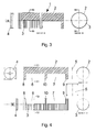
- the in Fig.1 shown in individual parts rotary valve 1 consists of an outer tube segment 2, an inner tube segment 3, an electric drive unit 4 and a closure cover 5.
- the outer tube segment 2 may be made of metal or plastic and is cut out of a tube such that in the region of a first incision 6 and a second incision 7, the tube is bisected in the longitudinal direction, in the region of the two incisions 6, 7 a half tube with a 180 ° sheath as in Fig.1 shown to form.
- Through the two incisions 6, 7 still remain a first Rohrendabêt 8, a second Rohrendab songs 9 and a pipe center portion 10 with a full 360 ° -Ummantelung left.
- the diameter of the inner tube segment 3 is slightly smaller than the diameter of the outer tube segment 2, so that in the further production, the inner tube segment 3 can be pushed into the outer tube segment 2, wherein in the end position of the first tube end 8 of the outer tube segment 2 with the first tube end portion 8 of Inner tube segment 3 overlaps and the tube middle section 10 of the outer tube segment 2 overlaps with the second tube end portion 9 of the inner tube segment 3.
- the electric drive unit 4 is then attached and the other end face of the rotary valve 1 remains open.
- This type of rotary valve 1 is referred to as a large rotary valve 1.
- Fig.2 shows the open position of the large rotary valve 1, wherein the concentrically arranged half-tubes of the outer tube segment 2 and the inner tube segment 3 overlap congruent.
- the rotary valve 1 is now open. If the inner tube segment 3 from the congruent position rotated 180 ° relative to the outer tube segment 2, then the two half-tubes of the outer tube segment 2 and the inner tube segment 3 face each other and the rotary valve 1 is in the closed position, as in Figure 3 shown because the area of the first incision 6 is now closed.
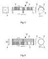
- the in Figure 4 shown in parts rotary valve 12 is referred to as a small rotary valve.
- This small rotary valve is produced in the same way as the large rotary valve 1, but with the difference that the length of the inner tube segment 3 corresponds to the length of the outer tube segment 2.
- the inner tube segment 3 also has two cuts 6, 7 as the outer tube segment 2.
- the electric drive unit 4 and opposite, in contrast to the rotary valve 1, always the closure lid 5 is arranged.
- the small rotary valve 12 is brought from an open position to a closed position, in contrast to the large rotary valve 1, the small rotary valve 12th is closed in the region of the two incisions 6, 7.
- FIG. 7 shows a section through the heat exchanger 11, wherein on one end face of the heat exchanger 11, two large rotary valve 1 and between a small rotary valve 12 are arranged. At the other end face of the heat exchanger 11, no complete large rotary valve 1 but only two outer tube segments 2 as in the large rotary valve 1 are provided. Each outer tube segment 2 is closed at one end face with a closure lid 5. In between there is a small rotary valve 12. Between the rotary valves 12 and the heat exchanger 11, an insulating intermediate plate is provided, which separates the two heat exchanger halves.
- Fig.8 and Fig.9 show the normal heat exchanger operation.
- a first air flow 13 enters into the outer tube segment 2 with respect to the closure lid 5 and flows through the draft of a first plane of the heat exchanger 11 in the large rotary valve 1.
- the inner tube segment 3 of the large rotary valve 1 is rotated so that the inner tube segment 3 and the outer tube segment. 2 are congruent, so that the rotary valve 1 is open and the first air flow 13 can freely pass through the rotary valve 1 with respect to the drive unit 4.
- the second air flow 14 occurs in relation to the drive unit 4 in the inner tube segment 3 of the large rotary valve 1.
- the inner tube segment 3 is rotated so that it is congruent with the outer tube segment 2, so that the rotary valve 1 is opened.
- the second air flow 14 thus flows counter to the first air flow 13 through the draft of a second plane of the heat exchanger 11 and further into the outer tube segment 2 and then exits through the opening with respect to the closure lid 5. This results in an almost complete temperature transfer from the first air stream 13 to the second air stream 14.
- Fig.10 to Fig.12 show the avoidance of temperature transfer from the first air flow 13 to the second air flow 14.
- the two large rotary valves 1 are closed halfway, by the respective inner tube segments 3 are rotated by 180 ° relative to the corresponding outer tube segments 2.
- the first air flow 13 now passes unchanged through the opening in the outer tube segment 2, but can now only pass through the air passages of the first level of the heat exchanger 11 in the outer tube segment 2 and exit through the opening with respect to the drive unit 4.
- the second air duct 14 enters into the outer tube segment 2 of the rotary valve 1 with respect to the drive unit 4 and can only flow through the region of the open incision into the air flows of the second plane of the heat exchanger 11 and exit through the outer tube segment 2 again with respect to the closure lid 5.
- the night-time cooling system can contribute to room cooling without significant energy expenditure.
- the two small rotary valves 12 are closed.
- part of the first air flow 13 can be supplied to the second air flow 14.
- This function is advantageous in an air conditioner when the outside temperature is higher than the desired room temperature and the Peltier heat pump following in the air conditioner in the air flow direction is operating in the cooling mode.
- the second air flow acting 14 exhaust air flow as much outside air via this bypass zulugeben that with the larger air flow volume, the larger amount of heat can be absorbed and carried as exhaust air to the outside becomes.
- the cooling performance on the warm side of the Peltier heat pump improves solely by raising the air flow through a fan.
- FIG. 13 shows how part of the exhaust air flow is supplied to the outside air flow. This is advantageous for receiving the larger amount of heat on the hot side of the Peltier heat pump in the heating mode and is supplied as supply air to the room. Only by increasing the capacity of a fan in the air conditioner so the heating capacity is significantly improved.
- the volume of the first air stream 13 can be optimized for the heat transport as supply air.
- the proportion of exhaust air, which is supplied as a bypass to the air stream 13, is characterized in recirculation mode. Meanwhile, the small rotary valve 12 is closed.
- the heat exchanger according to the invention with air flow directing elements is compact and also allows a compact design of ventilation, heating and air conditioning units. Another advantage is the low air resistance of the air flow control elements and thus the avoidance of flow noise.
Landscapes
- Engineering & Computer Science (AREA)
- Mechanical Engineering (AREA)
- Physics & Mathematics (AREA)
- Thermal Sciences (AREA)
- Chemical & Material Sciences (AREA)
- Combustion & Propulsion (AREA)
- General Engineering & Computer Science (AREA)
- Heat-Exchange Devices With Radiators And Conduit Assemblies (AREA)
- Multiple-Way Valves (AREA)
Abstract
Description
- Die Erfindung bezieht sich auf einen Wärmetauscher mit Luftstromlenkungselementen.
- Ein derartiger Wärmetauscher ist durch das deutsche Gebrauchsmuster 91 10 870.5 bekannt. Der Wärmetauscher wird in einem Klimagerät für ein Kraftfahrzeug verwendet, wobei ein Luftstromlenkungselement in Form einer Luftklappe vorgesehen ist, mit welcher die Frischluftzufuhr und die Warmluftzufuhr gesteuert werden. Durch die Stellung der Luftklappe kann entweder die Frischluftzufuhr oder die Warmluftzufuhr abgesperrt werden oder es kann eine Beimischung der Warmluft zur Frischluft erfolgen. Luftklappen haben den Nachteil, dass ein großer Strömungswiderstand gegeben ist und dass Strömungsgeräusche entstehen. Da die Luftklappe außerhalb des Wärmetauschers angeordnet ist, ist zusätzlich ein großer Platzbedarf erforderlich.
- Die Aufgabe der Erfindung wird somit darin gesehen, den Wärmetauscher der eingangs genannten Art derart weiterzuentwickeln, dass ein kompakter Wärmetauscher entsteht, bei welchem die Luftstromlenkungselemente einen geringen Strömungswiderstand aufweisen und welche kaum wahrnehmbare Geräusche verursachen. Zusätzlich soll dies mit konstruktiv einfachen Mitteln erreicht werden.
- Zur Lösung dieser Aufgabe wird bei einem Wärmetauscher gemäß dem Oberbegriff des Anspruchs 1 erfindungsgemäß vorgeschlagen, dass die Luftstromlenkungselemente integrierte Drehschieber sind, welche an den beiden als Lufteintrittsseite und Luftaustrittsseite wirkenden Stirnseiten des Wärmetauschers angeordnet sind, wobei jeder Drehschieber aus einem Außenrohrsegment und einem gegenüber dem Außenrohrsegment drehbaren Innenrohrsegment besteht.
- Bei dem erfindungsgemäßen Wärmetauscher sind die Drehschieber in dem Wärmetauscher integriert, so dass ein kompakter Wärmetauscher entsteht, welcher wenig Platz beansprucht. Die Drehschieber selbst haben durch ihre rohrförmige Ausbildung einen geringen Strömungswiderstand, so dass bei Betrieb praktisch keine Strömungsgeräusche entstehen. Durch die Stellung des Innenrohrsegments und des Außenrohrsegments zueinander wird die Lenkung der Luftströme bestimmt. Ein derartiger Drehschieber ist konstruktiv einfach herstellbar, da er lediglich aus zwei Rohrelementen aufgebaut ist.
- Um mittels der Rohrsegmente eine offene Stellung und eine geschlossene Stellung des Drehschiebers zu definieren, sieht eine Ausbildung der Erfindung vor, dass das Innenrohrsegment und das Außenrohrsegment je einem in Längsrichtung teilweise halbierten Rohr mit einer 180°-Ummantelung entspricht. Bei einer deckungsgleichen Stellung des Innenrohrsegments und des Außenrohrsegments ist der Drehschieber geöffnet, während bei einer gegenüberstehenden Stellung des Innenrohrsegments zum Außenrohrsegment der Drehschieber geschlossen ist. Vorteilhafterweise ist in der geschlossenen Stellung des Drehschiebers das Innenrohrsegment zum Außenrohrsegment gegenüber der deckungsgleichen Stellung genau um 180° verdreht.
- Bei den in dem Wärmetauscher integrierten Drehschiebern wird zwischen zwei unterschiedlichen Konstruktionen von Drehschiebern unterschieden. Es sind große Drehschieber und kleine Drehschieber vorgesehen. Bei dem großen Drehschieber entspricht die Länge des Innenrohrsegments vorteilhafterweise der Hälfte der Länge des Außenrohrsegments, während bei dem kleinen Drehschieber die Länge des Innenrohrsegments der Länge des Außenrohrsegments entspricht. Bei beiden Arten von Drehschiebern ist das Innenrohrsegment konzentrisch innerhalb des Außenrohrsegmentes angeordnet.
- Je nach Bedarf kann eine unterschiedliche Anzahl der beiden Arten von Drehschiebern innerhalb des Wärmetauschers integriert sein. Zweckmäßigerweise sind an einer Stirnseite des Wärmetauschers drei Drehschieber vorgesehen, wobei zwischen zwei großen Drehschiebern ein kleiner Drehschieber angeordnet ist.
- Die Erfindung wird nachstehend anhand der Zeichnung näher erläutert. Die Zeichnung zeigt ein Ausführungsbeispiel der Erfindung. Hierbei stellen dar:
-
Fig.1 eine Ansicht von Einzelteilen eines großen Drehschiebers, teilweise in Schnittdarstellung, -
Fig.2 einen Längsschnitt durch einen großen Drehschieber gemäßFig.1 in offener Stellung, zusammen mit einem Schnitt entlang der Linie B1-B1, -
Fig.3 einen Längsschnitt durch einen großen Drehschieber gemäßFig.1 in geschlossener Stellung, zusammen mit einem Schnitt entlang der Linie B3-B3, -
Fig.4 eine Ansicht von Einzelteilen eines kleinen Drehschiebers, teilweise in Schnittdarstellung, -
Fig.5 einen Längsschnitt durch einen kleinen Drehschieber gemäßFig.4 in offener Stellung, zusammen mit einem Schnitt, -
Fig.6 einen Längsschnitt durch einen kleinen Drehschieber gemäßFig.4 in geschlossener Stellung, zusammen mit einem Schnitt, -
Fig.7 einen Schnitt durch den erfindungsgemäßen Wärmetauscher mit eingezeichneten Luftströmen und mit den großen Drehschiebern in offener Stellung, -
Fig.8 einen Schnitt entlang der Linie F1-F1 inFig.7 , -
Fig.9 einen Schnitt entlang der Linie E1-E1 inFig.7 , -
Fig.10 einen Schnitt durch den erfindungsgemäßen Wärmetauscher mit eingezeichneten Luftströmen und mit den großen Drehschiebern in geschlossener Stellung, -
Fig.11 einen Schnitt entlang der Linie F2-F2 inFig.10 , -
Fig.12 einen Schnitt entlang der Linie E2-E2 inFig.10 , -
Fig.13 einen Schnitt durch den erfindungsgemäßen Wärmetauscher mit den kleinen Drehschiebern in offener Stellung, -
Fig.14 einen Schnitt entlang der Linie G-G inFig.13 , -
Fig.15 einen Schnitt entlang der Linie H-H inFig.13 und -
Fig.16 einen Schnitt entlang der Linie I-I inFig.13 . - Der in
Fig.1 in Einzelteilen gezeigte Drehschieber 1 besteht aus einem Außenrohrsegment 2, einem Innenrohrsegment 3, einer elektrischen Antriebseinheit 4 und einem Verschlussdeckel 5. Das Außenrohrsegment 2 kann aus Metall oder Kunststoff hergestellt sein und wird aus einem Rohr derart ausgeschnitten, dass im Bereich eines ersten Einschnitts 6 und eines zweiten Einschnitts 7 das Rohr in Längsrichtung halbiert wird, um im Bereich der beiden Einschnitte 6, 7 ein Halbrohr mit einer 180°-Ummantelung wie inFig.1 gezeigt zu bilden. Durch die beiden Einschnitte 6, 7 bleiben noch ein erster Rohrendabschnitt 8, ein zweiter Rohrendabschnitt 9 und ein Rohrmittelabschnitt 10 mit einer vollen 360°-Ummantelung übrig. Diese Rohrabschnitte 8, 9, 10 werden teilweise als Befestigung in dem Wärmetauscher 11, welcher ein Gegenstromwärmetauscher ist, verwendet. In gleicher Weise wird das Innenrohrsegment 3 hergestellt, wobei allerdings die Länge des Innenrohrsegments 3 der Hälfte der Länge des Außenrohrsegments 2 entspricht und somit nur ein erster Einschnitt 6 gemacht wird. Mit einer vollen 360°-Ummantelung bleiben bei dem Innenrohrsegment 3 der erste Rohrendabschnitt 8 und der zweite Rohrendabschnitt 9 übrig. Der Durchmesser des Innenrohrsegments 3 ist etwas kleiner als der Durchmesser des Außenrohrsegments 2, so dass bei der weiteren Fertigung das Innenrohrsegment 3 in das Außenrohrsegment 2 geschoben werden kann, wobei sich in der Endstellung der erste Rohrendabschnitt 8 des Außenrohrsegments 2 mit dem ersten Rohrendabschnitt 8 des Innenrohrsegments 3 überlappt und der Rohrmittelabschnitt 10 des Außenrohrsegments 2 mit dem zweiten Rohrendabschnitt 9 des Innenrohrsegments 3 überlappt. An der einen Stirnseite des Drehschiebers wird dann die elektrische Antriebseinheit 4 angebracht und die andere Stirnseite des Drehschiebers 1 bleibt offen. Dieser Typ des Drehschiebers 1 wird als großer Drehschieber 1 bezeichnet. -
Fig.2 zeigt die offene Stellung des großen Drehschiebers 1, wobei sich die konzentrisch angeordneten Halbrohre des Außenrohrsegments 2 und des Innenrohrsegments 3 deckungsgleich überlappen. Im Bereich des ersten Einschnitts 6 ist der Drehschieber 1 nun offen. Wird das Innenrohrsegment 3 aus der deckungsgleichen Stellung um 180° gegenüber dem Außenrohrsegment 2 gedreht, dann stehen sich die beiden Halbrohre des Außenrohrsegments 2 und des Innenrohrsegments 3 gegenüber und der Drehschieber 1 befindet sich in der geschlossenen Stellung, wie inFig.3 gezeigt, da der Bereich des ersten Einschnitts 6 nun verschlossen ist. - Der in
Fig.4 in Einzelteilen gezeigte Drehschieber 12 wird als kleiner Drehschieber bezeichnet. Dieser kleine Drehschieber wird in gleicher Weise wie der große Drehschieber 1 hergestellt, allerdings mit dem Unterschied, dass die Länge des Innenrohrsegments 3 der Länge des Außenrohrsegments 2 entspricht. Somit weist das Innenrohrsegment 3 ebenfalls zwei Einschnitte 6, 7 wie das Außenrohrsegment 2 auf. An der einen Stirnseite ist bei diesem Drehschieber 12 die elektrische Antriebseinheit 4 und gegenüber, im Gegensatz zum Drehschieber 1, immer der Verschlussdeckel 5 angeordnet. Das Funktionsprinzip ist dasselbe wie bei dem großen Drehschieber 1. Durch Drehung des Innenrohrsegments 3 gegenüber dem Außenrohrsegment 2 um 180° wird der kleine Drehschieber 12 von einer geöffneten Stellung in eine geschlossene Stellung gebracht, wobei im Gegensatz zu dem großen Drehschieber 1 der kleine Drehschieber 12 im Bereich der beiden Einschnitte 6, 7 verschlossen ist. -
Fig.7 zeigt einen Schnitt durch den Wärmetauscher 11, wobei an einer Stirnseite des Wärmetauschers 11 zwei große Drehschieber 1 und dazwischen ein kleiner Drehschieber 12 angeordnet sind. An der anderen Stirnseite des Wärmetauschers 11 sind keine vollständigen großen Drehschieber 1 sondern lediglich zwei Außenrohrsegmente 2 wie bei dem großen Drehschieber 1 vorgesehen. Jedes Außenrohrsegment 2 ist an einer Stirnseite mit einem Verschlussdeckel 5 verschlossen. Dazwischen befindet sich ein kleiner Drehschieber 12. Zwischen den Drehschiebern 12 und dem Wärmetauscher 11 ist je eine isolierende Zwischenplatte vorgesehen, die die beiden Wärmetauscherhälften trennt. -
Fig.8 und Fig.9 zeigen den normalen Wärmetauscherbetrieb. Ein erster Luftstrom 13 tritt gegenüber dem Verschlussdeckel 5 in das Außenrohrsegment 2 ein und strömt durch die Luftzüge einer ersten Ebene des Wärmetauschers 11 in den großen Drehschieber 1. Das Innenrohrsegment 3 des großen Drehschiebers 1 ist so gedreht, dass das Innenrohrsegment 3 und das Außenrohrsegment 2 deckungsgleich sind, so dass der Drehschieber 1 geöffnet ist und der erste Luftstrom 13 ungehindert durch den Drehschieber 1 gegenüber der Antriebseinheit 4 austreten kann. Der zweite Luftstrom 14 tritt gegenüber der Antriebseinheit 4 in das Innenrohrsegment 3 des großen Drehschiebers 1. Das Innenrohrsegment 3 ist so gedreht, dass es deckungsgleich mit dem Außenrohrsegment 2 ist, so dass der Drehschieber 1 geöffnet ist. Der zweite Luftstrom 14 strömt somit entgegen dem ersten Luftstrom 13 durch die Luftzüge einer zweiten Ebene des Wärmetauschers 11 und weiter in das Außenrohrsegment 2 und tritt dann durch die Öffnung gegenüber dem Verschlussdeckel 5 aus. Hierdurch ergibt sich eine fast vollständige Temperaturübertragung von dem ersten Luftstrom 13 zu dem zweiten Luftstrom 14. -
Fig.10 bis Fig.12 zeigen die Vermeidung von Temperaturübertragung von dem ersten Luftstrom 13 zu dem zweiten Luftstrom 14. Die beiden großen Drehschieber 1 sind auf halber Länge geschlossen, indem die jeweiligen Innenrohrsegmente 3 um 180° gegenüber den entsprechenden Außenrohrsegmenten 2 gedreht sind. Der erste Luftstrom 13 tritt nun zwar unverändert durch die Öffnung in das Außenrohrsegment 2 ein, kann jetzt aber nur durch die Luftzüge der ersten Ebene des Wärmetauschers 11 in das Außenrohrsegment 2 streichen und durch die Öffnung gegenüber der Antriebseinheit 4 austreten. Der zweite Luftzug 14 tritt gegenüber der Antriebseinheit 4 in das Außenrohrsegment 2 des Drehschiebers 1 ein und kann nur noch durch den Bereich des offenen Einschnitts in die Luftzüge der zweiten Ebene des Wärmetauschers 11 strömen und durch das Außenrohrsegment 2 gegenüber dem Verschlussdeckel 5 wieder austreten. Es findet kein Wärmeaustausch statt. Diese Funktion ist vorteilhaft, wenn abends die Außentemperatur unter die gewünschte Raumtemperatur absinkt. Dadurch kann die Nachtkühle ohne nennenswerten Energieaufwand zur Raumkühlung beitragen. Für den vorstehend beschriebenen normalen Wärmetauscherbetrieb und den Betrieb zur Vermeidung von Temperaturübertragung von dem ersten Luftstrom 13 zu dem zweiten Luftstrom 14 sind die beiden kleinen Drehschieber 12 geschlossen. - Wenn die beiden kleinen Drehschieber 12 geöffnet sind, dann kann vom ersten Luftstrom 13 ein Teil dem zweiten Luftstrom 14 zugeführt werden. Diese Funktion ist in einem Klimagerät von Vorteil, wenn die Außentemperatur höher ist als die gewünschte Raumtemperatur und die in dem Klimagerät in Luftströmungsrichtung folgende Peltier-Wärmepumpe im Kühlbetrieb arbeitet. Um den höheren Wärmeanteil abzuführen, der jetzt auf der Kaltseite der Peltier-Wärmepumpe entsteht, ist es vorteilhaft, dem als zweiter Luftstrom 14 wirkender Abluftstrom so viel Außenluft über diesen Bypaß beizugeben, dass mit dem größerem Luftstromvolumen die größere Wärmemenge aufgenommen werden kann und als Fortluft ins Freie getragen wird. Dadurch verbessert sich die Kühlleistung auf der Warmseite der Peltier-Wärmepumpe alleine durch Anheben der Luftleistung durch einen Ventilator. Durch Öffnen und Schließen des kleinen Drehschiebers 12 kann die Bypaßmenge stufenlos dem optimalen Bedarf angepasst werden. Währenddessen ist der andere kleine Drehschieber 12 geschlossen. In
Fig.13 ist dargestellt, wie vom Abluftstrom ein Teil dem Außenluftstrom zugeführt wird. Dies ist vorteilhaft zum Aufnehmen der größeren Wärmemenge auf der Warmseite der Peltier-Wärmepumpe im Heizbetrieb und wird als Zuluft dem Raum zugeführt. Nur durch Erhöhen der Förderleistung eines Ventilators im Klimagerät wird so die Heizleistung deutlich verbessert. Durch stufenloses Verstellen des Innenrohrsegments 3 kann das Volumen des ersten Luftstroms 13 für den Wärmetransport als Zuluft optimiert werden. Der Anteil Abluft, der als Bypaß dem Luftstrom 13 zugeführt wird, ist dadurch im Umluftbetrieb. Währenddessen ist der kleine Drehschieber 12 geschlossen. - Der erfindungsgemäße Wärmetauscher mit Luftstromlenkungselementen ist kompakt gebaut und ermöglicht zusätzlich eine kompakte Bauweise von Lüftungs-, Heiz- und Klimageräten. Ein weiterer Vorteil ist der geringe Luftwiderstand der Luftstromlenkungselemente und damit die Vermeidung von Strömungsgeräuschen.
Claims (11)
- Wärmetauscher mit Luftstromlenkungselementen,
dadurch gekennzeichnet,
dass die Luftstromlenkungselemente integrierte Drehschieber (1,12) sind, welche an den beiden als Lufteintrittsseite und Luftaustrittsseite wirkenden Stirnseiten des Wärmetauschers (11) angeordnet sind, wobei jeder Drehschieber (1,12) aus einem Außenrohrsegment (2) und einem gegenüber dem Außenrohrsegment (2) drehbaren Innenrohrsegment (3) besteht. - Wärmetauscher nach Anspruch 1,
dadurch gekennzeichnet,
dass das Innenrohrsegment (3) und das Außenrohrsegment (2) je einem in Längsrichtung teilweise halbierten Rohr mit einer 180°-Ummantelung entsprechen. - Wärmetauscher nach Anspruch 1 oder 2,
dadurch gekennzeichnet,
dass bei einer deckungsgleichen Stellung des Innenrohrsegments (3) und des Außenrohrsegments (2) der Drehschieber (1,12) geöffnet ist. - Wärmetauscher nach einem der vorhergehenden Ansprüche,
dadurch gekennzeichnet,
dass bei einer gegenüberstehenden Stellung des Innenrohrsegments (3) zum Außenrohrsegment (2) der Drehschieber (1,12) geschlossen ist. - Wärmetauscher nach einem der Ansprüche 3 oder 4,
dadurch gekennzeichnet,
dass in geschlossener Stellung des Drehschiebers (1,12) das Innenrohrsegment (3) zum Außenrohrsegment (2) gegenüber der deckungsgleichen Stellung um 180° verdreht ist. - Wärmetauscher nach einem der vorhergehenden Ansprüche,
dadurch gekennzeichnet,
dass das Innenrohrsegment (3) konzentrisch innerhalb des Außenrohrsegments (2) angeordnet ist. - Wärmetauscher nach einem der vorhergehenden Ansprüche,
dadurch gekennzeichnet,
dass die Länge des Innenrohrsegments (3) der Länge des Außenrohrsegments (2) entspricht. - Wärmetauscher nach einem der vorhergehenden Ansprüche 1 bis 6,
dadurch gekennzeichnet,
dass die Länge des Innenrohrsegments (3) der Hälfte der Länge des Außenrohrsegments (2) entspricht. - Wärmetauscher nach einem der vorhergehenden Ansprüche,
dadurch gekennzeichnet,
dass an einer ersten Stirnseite des Wärmetauschers (11) drei Drehschieber (1,12) angeordnet sind. - Wärmetauscher nach Anspruch 9,
dadurch gekennzeichnet,
dass die drei Drehschieber (1,12) zwei große Drehschieber (1) und ein kleiner Drehschieber (12) sind, wobei zwischen den zwei großen Drehschiebern (1) der kleine Drehschieber (12) angeordnet ist. - Wärmetauscher nach einem der vorhergehenden Ansprüche,
dadurch gekennzeichnet,
dass an einer zweiten Stirnseite des Wärmetauschers (11) ein kleiner Drehschieber (12) angeordnet ist.
Applications Claiming Priority (1)
| Application Number | Priority Date | Filing Date | Title |
|---|---|---|---|
| DE202009010548U DE202009010548U1 (de) | 2009-08-04 | 2009-08-04 | Wärmetauscher mit Luftstromlenkungselementen |
Publications (2)
| Publication Number | Publication Date |
|---|---|
| EP2282137A1 true EP2282137A1 (de) | 2011-02-09 |
| EP2282137B1 EP2282137B1 (de) | 2013-05-29 |
Family
ID=41427637
Family Applications (1)
| Application Number | Title | Priority Date | Filing Date |
|---|---|---|---|
| EP10007375.8A Active EP2282137B1 (de) | 2009-08-04 | 2010-07-16 | Wärmetauschereinheit mit Luftstromlenkungselementen |
Country Status (2)
| Country | Link |
|---|---|
| EP (1) | EP2282137B1 (de) |
| DE (1) | DE202009010548U1 (de) |
Citations (3)
| Publication number | Priority date | Publication date | Assignee | Title |
|---|---|---|---|---|
| WO2001069154A1 (en) * | 2000-03-14 | 2001-09-20 | Air-Change Pty Limited | Heat exchanger |
| DE10013689A1 (de) * | 2000-03-21 | 2001-09-27 | Siegenia Frank Kg | Lüftungsvorrichtung |
| WO2006073232A1 (en) * | 2005-01-10 | 2006-07-13 | In Sook Chung | Heat exchanger and heat exchanging ventilator using the same |
Family Cites Families (1)
| Publication number | Priority date | Publication date | Assignee | Title |
|---|---|---|---|---|
| DE9110870U1 (de) | 1990-09-13 | 1991-10-24 | Siemens AG, 8000 München | Heiz- bzw. Klimagerät für ein Kraftfahrzeug |
-
2009
- 2009-08-04 DE DE202009010548U patent/DE202009010548U1/de not_active Expired - Lifetime
-
2010
- 2010-07-16 EP EP10007375.8A patent/EP2282137B1/de active Active
Patent Citations (3)
| Publication number | Priority date | Publication date | Assignee | Title |
|---|---|---|---|---|
| WO2001069154A1 (en) * | 2000-03-14 | 2001-09-20 | Air-Change Pty Limited | Heat exchanger |
| DE10013689A1 (de) * | 2000-03-21 | 2001-09-27 | Siegenia Frank Kg | Lüftungsvorrichtung |
| WO2006073232A1 (en) * | 2005-01-10 | 2006-07-13 | In Sook Chung | Heat exchanger and heat exchanging ventilator using the same |
Also Published As
| Publication number | Publication date |
|---|---|
| EP2282137B1 (de) | 2013-05-29 |
| DE202009010548U1 (de) | 2009-12-17 |
Similar Documents
| Publication | Publication Date | Title |
|---|---|---|
| EP0740617B1 (de) | Heizungs- und/oder klimaeinrichtung | |
| EP0127213B1 (de) | Vorrichtung zum Belüften und Heizen von Innenräumen, insbesondere Wohnräumen | |
| DE102008058817B4 (de) | Luft-Luft-Wärmetauscher | |
| DE4119474C2 (de) | Heiz- oder Klimaanlage für den Fahrgastraum eines Kraftfahrzeuges | |
| DE69016674T2 (de) | Wärmerückgewinnender ventilator. | |
| DE102006050826A1 (de) | Drehschieber mit mehreren Querschnittsverstellgliedern | |
| DE102008021015A1 (de) | Vorrichtung zur Mischung von gasförmigen Medien und zum Absperren eines Querschnitts | |
| DE3017431C2 (de) | Lüftungsvorrichtung für Räume mit zwei getrennten Strömungswegen zur Be- und Entlüftung | |
| EP1526976B2 (de) | Klimagehäuse | |
| DE102017218343A1 (de) | Verfahren zur verteilung von luftventilation in einem fahrzeug | |
| DE19518280A1 (de) | Vorrichtung zur Heizung und/oder Belüftung des Fahrgastraums | |
| DE102010006038B4 (de) | Vorrichtung zur Regelung eines Fluidstroms | |
| DE102010010711A1 (de) | Verfahren und Vorrichtung zum Lüften eines Objekts | |
| DE10240795A1 (de) | Wärmeübertrageranordnung und Heiz-/Kühlkreislauf für eine Klimaanlage eines Fahrzeugs und Verfahren zur Steuerung und/oder Regelung eines Heiz-/Kühlkreislaufes einer Klimaanlage | |
| DE102011008520B4 (de) | Klimaanlage zur Steuerung eines Luftstroms in einer Klimaanlage eines Fahrzeugs | |
| EP4232758A1 (de) | Verschlusseinheit einer lüftungsvorrichtung | |
| EP2282137B1 (de) | Wärmetauschereinheit mit Luftstromlenkungselementen | |
| DE102013102347A1 (de) | Raumlufttechnische Baugruppe | |
| EP2362153B1 (de) | Luftaustauschvorrichtung | |
| DE2020468B2 (de) | Luftseitig geregeltes Klimageraet fuer Vierleitersystem mit eingebautem Ventilator | |
| DE102009024255A1 (de) | Klappenanordnung | |
| DE9110870U1 (de) | Heiz- bzw. Klimagerät für ein Kraftfahrzeug | |
| EP1231088B1 (de) | Mehrkanalige Klimaanlage mit einheitlich leistungsgesteuertem Heizkörper | |
| DE1604125B2 (de) | Luftaufbereitungsanlage | |
| DE3335768A1 (de) | Heiz- und/oder klimaanlage fuer kraftfahrzeuge |
Legal Events
| Date | Code | Title | Description |
|---|---|---|---|
| PUAI | Public reference made under article 153(3) epc to a published international application that has entered the european phase |
Free format text: ORIGINAL CODE: 0009012 |
|
| AK | Designated contracting states |
Kind code of ref document: A1 Designated state(s): AL AT BE BG CH CY CZ DE DK EE ES FI FR GB GR HR HU IE IS IT LI LT LU LV MC MK MT NL NO PL PT RO SE SI SK SM TR |
|
| AX | Request for extension of the european patent |
Extension state: BA ME RS |
|
| 17P | Request for examination filed |
Effective date: 20110721 |
|
| REG | Reference to a national code |
Ref country code: DE Ref legal event code: R079 Ref document number: 502010003407 Country of ref document: DE Free format text: PREVIOUS MAIN CLASS: F24F0012000000 Ipc: B60H0001000000 |
|
| 17Q | First examination report despatched |
Effective date: 20121102 |
|
| GRAP | Despatch of communication of intention to grant a patent |
Free format text: ORIGINAL CODE: EPIDOSNIGR1 |
|
| RIC1 | Information provided on ipc code assigned before grant |
Ipc: B60H 1/00 20060101AFI20121128BHEP |
|
| GRAS | Grant fee paid |
Free format text: ORIGINAL CODE: EPIDOSNIGR3 |
|
| GRAA | (expected) grant |
Free format text: ORIGINAL CODE: 0009210 |
|
| AK | Designated contracting states |
Kind code of ref document: B1 Designated state(s): AL AT BE BG CH CY CZ DE DK EE ES FI FR GB GR HR HU IE IS IT LI LT LU LV MC MK MT NL NO PL PT RO SE SI SK SM TR |
|
| REG | Reference to a national code |
Ref country code: GB Ref legal event code: FG4D Free format text: NOT ENGLISH |
|
| REG | Reference to a national code |
Ref country code: CH Ref legal event code: EP |
|
| REG | Reference to a national code |
Ref country code: AT Ref legal event code: REF Ref document number: 614142 Country of ref document: AT Kind code of ref document: T Effective date: 20130615 |
|
| REG | Reference to a national code |
Ref country code: IE Ref legal event code: FG4D Free format text: LANGUAGE OF EP DOCUMENT: GERMAN |
|
| REG | Reference to a national code |
Ref country code: DE Ref legal event code: R096 Ref document number: 502010003407 Country of ref document: DE Effective date: 20130725 |
|
| REG | Reference to a national code |
Ref country code: LT Ref legal event code: MG4D |
|
| PG25 | Lapsed in a contracting state [announced via postgrant information from national office to epo] |
Ref country code: GR Free format text: LAPSE BECAUSE OF FAILURE TO SUBMIT A TRANSLATION OF THE DESCRIPTION OR TO PAY THE FEE WITHIN THE PRESCRIBED TIME-LIMIT Effective date: 20130830 Ref country code: FI Free format text: LAPSE BECAUSE OF FAILURE TO SUBMIT A TRANSLATION OF THE DESCRIPTION OR TO PAY THE FEE WITHIN THE PRESCRIBED TIME-LIMIT Effective date: 20130529 Ref country code: LT Free format text: LAPSE BECAUSE OF FAILURE TO SUBMIT A TRANSLATION OF THE DESCRIPTION OR TO PAY THE FEE WITHIN THE PRESCRIBED TIME-LIMIT Effective date: 20130529 Ref country code: IS Free format text: LAPSE BECAUSE OF FAILURE TO SUBMIT A TRANSLATION OF THE DESCRIPTION OR TO PAY THE FEE WITHIN THE PRESCRIBED TIME-LIMIT Effective date: 20130929 Ref country code: SI Free format text: LAPSE BECAUSE OF FAILURE TO SUBMIT A TRANSLATION OF THE DESCRIPTION OR TO PAY THE FEE WITHIN THE PRESCRIBED TIME-LIMIT Effective date: 20130529 Ref country code: PT Free format text: LAPSE BECAUSE OF FAILURE TO SUBMIT A TRANSLATION OF THE DESCRIPTION OR TO PAY THE FEE WITHIN THE PRESCRIBED TIME-LIMIT Effective date: 20130930 Ref country code: ES Free format text: LAPSE BECAUSE OF FAILURE TO SUBMIT A TRANSLATION OF THE DESCRIPTION OR TO PAY THE FEE WITHIN THE PRESCRIBED TIME-LIMIT Effective date: 20130909 Ref country code: NO Free format text: LAPSE BECAUSE OF FAILURE TO SUBMIT A TRANSLATION OF THE DESCRIPTION OR TO PAY THE FEE WITHIN THE PRESCRIBED TIME-LIMIT Effective date: 20130829 Ref country code: SE Free format text: LAPSE BECAUSE OF FAILURE TO SUBMIT A TRANSLATION OF THE DESCRIPTION OR TO PAY THE FEE WITHIN THE PRESCRIBED TIME-LIMIT Effective date: 20130529 |
|
| REG | Reference to a national code |
Ref country code: NL Ref legal event code: VDEP Effective date: 20130529 |
|
| PG25 | Lapsed in a contracting state [announced via postgrant information from national office to epo] |
Ref country code: HR Free format text: LAPSE BECAUSE OF FAILURE TO SUBMIT A TRANSLATION OF THE DESCRIPTION OR TO PAY THE FEE WITHIN THE PRESCRIBED TIME-LIMIT Effective date: 20130529 Ref country code: PL Free format text: LAPSE BECAUSE OF FAILURE TO SUBMIT A TRANSLATION OF THE DESCRIPTION OR TO PAY THE FEE WITHIN THE PRESCRIBED TIME-LIMIT Effective date: 20130529 Ref country code: BG Free format text: LAPSE BECAUSE OF FAILURE TO SUBMIT A TRANSLATION OF THE DESCRIPTION OR TO PAY THE FEE WITHIN THE PRESCRIBED TIME-LIMIT Effective date: 20130829 |
|
| PG25 | Lapsed in a contracting state [announced via postgrant information from national office to epo] |
Ref country code: LV Free format text: LAPSE BECAUSE OF FAILURE TO SUBMIT A TRANSLATION OF THE DESCRIPTION OR TO PAY THE FEE WITHIN THE PRESCRIBED TIME-LIMIT Effective date: 20130529 |
|
| BERE | Be: lapsed |
Owner name: BLUM, THEODOR Effective date: 20130731 |
|
| PG25 | Lapsed in a contracting state [announced via postgrant information from national office to epo] |
Ref country code: EE Free format text: LAPSE BECAUSE OF FAILURE TO SUBMIT A TRANSLATION OF THE DESCRIPTION OR TO PAY THE FEE WITHIN THE PRESCRIBED TIME-LIMIT Effective date: 20130529 Ref country code: SK Free format text: LAPSE BECAUSE OF FAILURE TO SUBMIT A TRANSLATION OF THE DESCRIPTION OR TO PAY THE FEE WITHIN THE PRESCRIBED TIME-LIMIT Effective date: 20130529 Ref country code: DK Free format text: LAPSE BECAUSE OF FAILURE TO SUBMIT A TRANSLATION OF THE DESCRIPTION OR TO PAY THE FEE WITHIN THE PRESCRIBED TIME-LIMIT Effective date: 20130529 Ref country code: CZ Free format text: LAPSE BECAUSE OF FAILURE TO SUBMIT A TRANSLATION OF THE DESCRIPTION OR TO PAY THE FEE WITHIN THE PRESCRIBED TIME-LIMIT Effective date: 20130529 |
|
| PG25 | Lapsed in a contracting state [announced via postgrant information from national office to epo] |
Ref country code: MC Free format text: LAPSE BECAUSE OF FAILURE TO SUBMIT A TRANSLATION OF THE DESCRIPTION OR TO PAY THE FEE WITHIN THE PRESCRIBED TIME-LIMIT Effective date: 20130529 Ref country code: NL Free format text: LAPSE BECAUSE OF FAILURE TO SUBMIT A TRANSLATION OF THE DESCRIPTION OR TO PAY THE FEE WITHIN THE PRESCRIBED TIME-LIMIT Effective date: 20130529 Ref country code: IT Free format text: LAPSE BECAUSE OF FAILURE TO SUBMIT A TRANSLATION OF THE DESCRIPTION OR TO PAY THE FEE WITHIN THE PRESCRIBED TIME-LIMIT Effective date: 20130529 Ref country code: RO Free format text: LAPSE BECAUSE OF FAILURE TO SUBMIT A TRANSLATION OF THE DESCRIPTION OR TO PAY THE FEE WITHIN THE PRESCRIBED TIME-LIMIT Effective date: 20130529 |
|
| PLBE | No opposition filed within time limit |
Free format text: ORIGINAL CODE: 0009261 |
|
| STAA | Information on the status of an ep patent application or granted ep patent |
Free format text: STATUS: NO OPPOSITION FILED WITHIN TIME LIMIT |
|
| REG | Reference to a national code |
Ref country code: IE Ref legal event code: MM4A |
|
| PG25 | Lapsed in a contracting state [announced via postgrant information from national office to epo] |
Ref country code: BE Free format text: LAPSE BECAUSE OF NON-PAYMENT OF DUE FEES Effective date: 20130731 |
|
| 26N | No opposition filed |
Effective date: 20140303 |
|
| REG | Reference to a national code |
Ref country code: DE Ref legal event code: R097 Ref document number: 502010003407 Country of ref document: DE Effective date: 20140303 |
|
| PG25 | Lapsed in a contracting state [announced via postgrant information from national office to epo] |
Ref country code: IE Free format text: LAPSE BECAUSE OF NON-PAYMENT OF DUE FEES Effective date: 20130716 |
|
| GBPC | Gb: european patent ceased through non-payment of renewal fee |
Effective date: 20140716 |
|
| PG25 | Lapsed in a contracting state [announced via postgrant information from national office to epo] |
Ref country code: SM Free format text: LAPSE BECAUSE OF FAILURE TO SUBMIT A TRANSLATION OF THE DESCRIPTION OR TO PAY THE FEE WITHIN THE PRESCRIBED TIME-LIMIT Effective date: 20130529 Ref country code: GB Free format text: LAPSE BECAUSE OF NON-PAYMENT OF DUE FEES Effective date: 20140716 |
|
| PG25 | Lapsed in a contracting state [announced via postgrant information from national office to epo] |
Ref country code: CY Free format text: LAPSE BECAUSE OF FAILURE TO SUBMIT A TRANSLATION OF THE DESCRIPTION OR TO PAY THE FEE WITHIN THE PRESCRIBED TIME-LIMIT Effective date: 20130529 Ref country code: MT Free format text: LAPSE BECAUSE OF FAILURE TO SUBMIT A TRANSLATION OF THE DESCRIPTION OR TO PAY THE FEE WITHIN THE PRESCRIBED TIME-LIMIT Effective date: 20130529 Ref country code: TR Free format text: LAPSE BECAUSE OF FAILURE TO SUBMIT A TRANSLATION OF THE DESCRIPTION OR TO PAY THE FEE WITHIN THE PRESCRIBED TIME-LIMIT Effective date: 20130529 |
|
| PG25 | Lapsed in a contracting state [announced via postgrant information from national office to epo] |
Ref country code: LU Free format text: LAPSE BECAUSE OF NON-PAYMENT OF DUE FEES Effective date: 20130716 Ref country code: MK Free format text: LAPSE BECAUSE OF FAILURE TO SUBMIT A TRANSLATION OF THE DESCRIPTION OR TO PAY THE FEE WITHIN THE PRESCRIBED TIME-LIMIT Effective date: 20130529 Ref country code: HU Free format text: LAPSE BECAUSE OF FAILURE TO SUBMIT A TRANSLATION OF THE DESCRIPTION OR TO PAY THE FEE WITHIN THE PRESCRIBED TIME-LIMIT; INVALID AB INITIO Effective date: 20100716 |
|
| REG | Reference to a national code |
Ref country code: FR Ref legal event code: PLFP Year of fee payment: 7 |
|
| REG | Reference to a national code |
Ref country code: FR Ref legal event code: PLFP Year of fee payment: 8 |
|
| REG | Reference to a national code |
Ref country code: DE Ref legal event code: R082 Ref document number: 502010003407 Country of ref document: DE Representative=s name: PATENT- UND RECHTSANWAELTE LOESENBECK, SPECHT,, DE Ref country code: DE Ref legal event code: R082 Ref document number: 502010003407 Country of ref document: DE Representative=s name: LOESENBECK UND KOLLEGEN, DE |
|
| REG | Reference to a national code |
Ref country code: FR Ref legal event code: PLFP Year of fee payment: 9 |
|
| PG25 | Lapsed in a contracting state [announced via postgrant information from national office to epo] |
Ref country code: AL Free format text: LAPSE BECAUSE OF FAILURE TO SUBMIT A TRANSLATION OF THE DESCRIPTION OR TO PAY THE FEE WITHIN THE PRESCRIBED TIME-LIMIT Effective date: 20130529 |
|
| PGFP | Annual fee paid to national office [announced via postgrant information from national office to epo] |
Ref country code: FR Payment date: 20190730 Year of fee payment: 10 |
|
| PGFP | Annual fee paid to national office [announced via postgrant information from national office to epo] |
Ref country code: AT Payment date: 20190731 Year of fee payment: 10 |
|
| PGFP | Annual fee paid to national office [announced via postgrant information from national office to epo] |
Ref country code: CH Payment date: 20190730 Year of fee payment: 10 |
|
| REG | Reference to a national code |
Ref country code: CH Ref legal event code: PL |
|
| REG | Reference to a national code |
Ref country code: AT Ref legal event code: MM01 Ref document number: 614142 Country of ref document: AT Kind code of ref document: T Effective date: 20200716 |
|
| PG25 | Lapsed in a contracting state [announced via postgrant information from national office to epo] |
Ref country code: LI Free format text: LAPSE BECAUSE OF NON-PAYMENT OF DUE FEES Effective date: 20200731 Ref country code: CH Free format text: LAPSE BECAUSE OF NON-PAYMENT OF DUE FEES Effective date: 20200731 Ref country code: FR Free format text: LAPSE BECAUSE OF NON-PAYMENT OF DUE FEES Effective date: 20200731 |
|
| PG25 | Lapsed in a contracting state [announced via postgrant information from national office to epo] |
Ref country code: AT Free format text: LAPSE BECAUSE OF NON-PAYMENT OF DUE FEES Effective date: 20200716 |
|
| REG | Reference to a national code |
Ref country code: DE Ref legal event code: R084 Ref document number: 502010003407 Country of ref document: DE |
|
| PGFP | Annual fee paid to national office [announced via postgrant information from national office to epo] |
Ref country code: DE Payment date: 20260130 Year of fee payment: 16 |