EP2282090A2 - Valve, in particular pressure regulating valve - Google Patents
Valve, in particular pressure regulating valve Download PDFInfo
- Publication number
- EP2282090A2 EP2282090A2 EP20100008045 EP10008045A EP2282090A2 EP 2282090 A2 EP2282090 A2 EP 2282090A2 EP 20100008045 EP20100008045 EP 20100008045 EP 10008045 A EP10008045 A EP 10008045A EP 2282090 A2 EP2282090 A2 EP 2282090A2
- Authority
- EP
- European Patent Office
- Prior art keywords
- control
- valve
- control piece
- plastic
- pin
- Prior art date
- Legal status (The legal status is an assumption and is not a legal conclusion. Google has not performed a legal analysis and makes no representation as to the accuracy of the status listed.)
- Withdrawn
Links
Images


Classifications
-
- F—MECHANICAL ENGINEERING; LIGHTING; HEATING; WEAPONS; BLASTING
- F16—ENGINEERING ELEMENTS AND UNITS; GENERAL MEASURES FOR PRODUCING AND MAINTAINING EFFECTIVE FUNCTIONING OF MACHINES OR INSTALLATIONS; THERMAL INSULATION IN GENERAL
- F16K—VALVES; TAPS; COCKS; ACTUATING-FLOATS; DEVICES FOR VENTING OR AERATING
- F16K31/00—Actuating devices; Operating means; Releasing devices
- F16K31/02—Actuating devices; Operating means; Releasing devices electric; magnetic
- F16K31/06—Actuating devices; Operating means; Releasing devices electric; magnetic using a magnet, e.g. diaphragm valves, cutting off by means of a liquid
- F16K31/0603—Multiple-way valves
- F16K31/0624—Lift valves
- F16K31/0634—Lift valves with fixed seats positioned between movable valve members
Definitions
- the invention relates to an actuatable by an electromagnet valve, in particular pressure control valve, wherein the armature of the electromagnet acts on a control element of the valve and this so, in particular axially offset, that the gap width of a in or on a valve element, such as a valve plate or a Valve sleeve provided gap changed or the gap opens or closes.
- a valve element such as a valve plate or a Valve sleeve provided gap changed or the gap opens or closes.
- the gap between the control element and arranged in the valve sleeve or the valve element valve seat is changed and thus the hydraulic pressure by the force of the electromagnet controlled at the work connection.
- the gap is bounded on the one hand by the valve seat and on the other hand by the boundary surface provided on the control element. Since the position of the control element and therefore the boundary surface is variable, and the distance (gap width) of the gap limiting surfaces changed.
- the control element consists of a made of metal, usually rotated control pin, on which an appropriate sealing surface is integrally worked, which cooperates with the valve seat.
- the electromagnet consists of a coil which can be acted upon by electric current and which surrounds an armature space.
- the axial position can be changed by the energization of the coil. Due to this axial change in position, the gap width changes on the control element, of course, thereby opening or closing of the valve is also possible.
- This object of the invention is achieved by a valve, as described above, wherein it is proposed that the control element from a control pin and a separately prepared, attached to the control pin control piece is formed and the control piece interacts with the gap.
- the invention proposes deliberately a multi-part structure of the control element, since the processing cost can be significantly reduced in particular for the rule. It is now possible to optimize the control to the particular application, for example, depending on operating pressure, medium, which is to be controlled, etc., and for the movement of the control piece always use the same rule pin. It therefore remains at very high lot sizes for standardized control pins, which are connected to appropriately optimized control pieces.
- the gap is delimited on the one hand by the valve seat and on the other hand by the boundary surface arranged on the control element.
- the gap width is defined z. B. over the shortest distance between the valve seat and the boundary surface.
- the sealing surface is part of the boundary surface.
- Rule and control pin are connected to each other in a suitable manner, for their material pairing here offer a variety of variants. It can be provided here, for example, bonds, but it is also possible to use a caulking, welding or other form-fitting or non-positive connection technology according to the invention. Since deliberately a material inequality between the control pin and the control pin is encompassed by the invention, the cost-effective production of a valve according to the invention is accompanied by a higher valve dynamics, if for the rule a lighter design, eg. B. is realized with a material of low density. Due to the building block principle offered here, a pressure control valve according to the invention, when using the same control pin, can also be optimized with respect to its valve dynamics by varying the respective control piece to the respective application.
- the invention includes applications in which rule pin and control are made the same material, but for example, the rule of a sheet material in a punch bend - Or punching lowering process has been obtained, which can be realized extremely inexpensively in a mass production is and then due to the small wall thickness of the rule contributes to a corresponding reduction in mass, but the material equality allows, for example, a welding of the control piece on the rule pin!
- valve plate or valve sleeve is described as an exemplary embodiment of the valve element. As far as a feature has been used only for the feature of the valve sleeve or the valve plate, or as defined here, this does not limit the invention in this area. Instead of the term valve bushing or valve plate is generally also the term valve element set.
- valves in particular pressure control valves, in which the armature acts directly or indirectly on the control element.
- an intermediate piece is provided, which optionally also flying, as well as the control element, is mounted.
- a provision or investment is achieved for example by appropriate return spring or the like.
- the control element in particular the control pin, fixed (and thus for example directly) is connected to the anchor. Both aforementioned variants are part of the invention.
- control piece is also very variable. It is possible that the control piece is disc-shaped, plate-shaped, conical, funnel-shaped or cone-shaped, with the realization possibilities of the regulating piece not being limited to these variants. For example, it is also possible to use ring-disk-like control pieces and so on. Of course, the appropriate choice of the rule on the application and on the design of the valve sleeve, in particular the valve seat why the different types of control are related to the respective application.
- funnel, conical or cone-like control pieces especially in fast-switching valves or rapidly controlling pressure control valves have advantages that they in addition to the mass reduction due to the higher valve dynamics also higher stability against pressure oscillations, due to the conical, conical - or funnel-like configuration. Therefore, then has the rule back an accessible chamber, as shown in the drawings (see reference numeral 22) is shown.
- the conical design further has a streamlined shape, which deflects the medium to be controlled in a suitable manner, following the conical surface.
- the control piece is formed thin-walled.
- the strength of the wall limiting the rule is much smaller than the diameter of the rule pin or its radius.
- the thin-walledness can also be exemplary (and therefore not limiting) with a wall thickness of less than 2 mm, in particular less than 1 mm, preferably less than 5/10 mm or 8/10 mm.
- the right wall thickness results in particular from the scope of the invention. It is clear that a correspondingly small material thickness also contributes to a lower mass and therefore to a corresponding valve dynamics.
- the thin-walled design of the control piece can be used both in discs, washer discs or conical or cone-shaped control pieces.
- This variant of the invention is not limited to the specific choice of material of the rule, the rule is made of metal, for example, light metal, aluminum or non-magnetizable or non-magnetizable metals or steels feasible.
- control piece In addition to a thin-walled design of the control piece, however, the invention also includes variants in which a conical or cone-like control piece, for example of solid material, is formed.
- control piece is characterized by a chamber or the relatively thin-walled boundary wall of the control piece encloses a chamber, the back, the cone tip is averse, accessible.
- the rule is connected with its conical or conical tip with the rule pin, such that the rule pin penetrates the rule and actually the design of the rule in this area is frustoconical, but what in the context of the invention with conical, funnel or cone-like is to be regarded as circumscribed.
- the (outer) boundary wall of the control piece runs at an acute angle to the longitudinal axis of the control pin and it thus forms a chamber which is also filled by the medium which is to be controlled or regulated.
- a circumferential groove or surface recess is provided, which is filled by the material of the control piece.
- the circumferential groove or the surface recess is not only filled by a metallic material of the control piece, the control piece may also be made of plastic, for example, and be arranged in a plastic injection process on the control pin, in which case the (still liquid) plastic the circumferential groove or a corresponding Surface recess fills.
- Control piece or regulating pin can therefore be formed, for example, from plastic, fiber-reinforced plastic, high-temperature-resistant plastic, high-strength plastic or metal, in particular non-magnetic or low-magnetic metal, such as corresponding steels and so on.
- the rule is also formed, for example, alternatively, for example, from a metal foil or a thin-walled metal part, it may alternatively be made of ceramic.
- novel high-temperature polymers having a melting temperature of about 380 ° C and a glass transition temperature of at least 150 ° C make it possible to provide cost-effective high temperature resistant and lightweight control pieces, and thus even more extreme applications of valves according to the invention, especially pressure control valves reliably dominate.
- control pin is guided in a core or is mounted and the core has a, the rule facing increase, which at least partially immersed in the chamber at least during axial withdrawal movement of the control pin.
- the control pin is guided in a core or is mounted and the core has a, the rule facing increase, which at least partially immersed in the chamber at least during axial withdrawal movement of the control pin.
- the conical, funnel-shaped or cone-like, optionally thin-walled realized control piece is "stiffened".
- a high stability against the vibrations of the medium is combined with a high valve dynamics due to the low weight of the control piece.
- the invention nevertheless also includes a solution in which a one-piece variant of the control element is produced, for example, from plastic or metal.
- plastic for example plastic, fiber reinforced plastic, high temperature resistant plastic, high strength plastic, metal, especially un-or low magnetic metal, thin-walled metal, sheet metal or foil or ceramic.
- corresponding steels are used, but it is also possible to use, for example, copper, aluminum or other metals in the context of the invention.
- the aforementioned metal choice refers to all applications of this invention or this application.
- control element of metallic materials, for example by turning or in a suitable method such as drawing and folding. It is also possible in principle that the material equality of control element and control element, the two separately produced elements are welded, for example, and are thus by definition one piece (due to material equality and the same material connection), but still the advantage of the invention was obtained in the production.
- the valve 1 according to the invention is shown schematically in the figures in different variants.
- the valve 1 shown is actuated or controlled by an electromagnet, not shown, but also to the invention.
- an electromagnet consists of an armature movably mounted in an armature space, which acts on the control pin 20.
- the armature space is surrounded by a coil which can be acted upon by electric current and generates a corresponding magnetic field. According to the generated magnetic field of the armature is offset axially, whereby the control pin 20 undergoes an axial displacement.
- control pin 20 is a part of the control element. 2
- the electromagnet would connect above the valve 1, the control pin 20 is stored or guided in the core 30 in a suitable manner.
- the valve 1 shown in the drawing is designed in particular as a pressure control valve.
- the valve 1 comprises a valve sleeve 15, in which a valve seat 11 is provided.
- the valve seat 11 is realized by a carrier 18 with a central penetration opening 17 and a guide cage 16 adjoining therebelow.
- control piece 21 With the double arrow 27, the axial adjustability of the control element 2 is indicated. Due to the conical configuration of the control piece 21, it is clear that the control piece 21 more or less releases the opening 17 provided in the valve seat 11, depending on the axial position (27) of the control piece, that is, enlarges or reduces the gap 10.
- the axial position of the control piece 21 is such that the gap 10 is almost completely closed, so the control piece 21 sits almost in the valve seat 11. This results in a large throttling of the media pressure and thus a corresponding reduction in pressure at the working port 14.
- the medium which is liquid or gaseous, for example, is applied to the pressure port 13.
- control element 2 is formed in two parts, that is, a control pin 20 and one of them separately prepared, optionally consisting of the same or different materials rule piece 21 has.
- a circumferential groove 24 is provided on the control pin 20 at a suitable location, in which, according to the method of connection of control piece 21 on control pin 20, material of Rule 21 penetrates. This makes it possible to realize a positive connection between the control piece 21 and the control pin 20, which is mechanically strong load.
- control piece 21 is not provided at the end of the control pin 20, but there is still a certain projection 26 below the connecting portion 28, which of course includes the circumferential groove 24. With the help of this supernatant 26 more control parts 12 of the valve 1 are driven for different purposes.
- the guide cage 16 connects, which serves to guide the supernatant 26 of the control pin.
- a ball 19 is held in a cage in such a way that it can only be displaced downward by the actuation of the control pin 20 or projection 26 and then releases a corresponding passage. In this case, the ball 19 is loose, that is separated from the control pin 20th
- This sealing surface 25 is part of the outer boundary surface or shell surface of the cone-like or cone-like realized control piece 21.
- a certain area of the boundary wall 23, which is relatively thin, is in the fully closed state of the valve as a sealing surface 25 on the Valve seat 11 and closes the gap 10 completely.
- the material thickness of the thin-walled boundary wall 23 is less than 1.5 mm, preferably less than 1.0 mm, in particular less than 800 ⁇ m. Based on the diameter of the rule pin, the wall thickness is less than 50%, preferably less than 35%, in particular less than 30%.
- Fig. 1 embodiment shown for the control piece 21 consists of a preferably obtained in a forming process Metal part, which is cone-shaped or funnel-like and is placed concentrically on the control pin 20 due to the central opening 29.
- Characteristic of the funnel-like (200) design of the control piece 21 is that a chamber 22 is provided which, if the control pin 20 would not be inserted, opens into the opening 29.
- the chamber 22 is accessible on the side facing away from the valve seat 11 and flows through in a suitable manner by the medium to be controlled.
- control piece 21 has a constant wall thickness. This results when a corresponding control piece is obtained from a metal part in a shaping stamping or punching method. This shape is inexpensive to implement.
- the material of the constriction 201 is pressed or caulked in the subsequent connection process in the circumferential groove 24 of the control pin 20 and so an exact and mechanically good loadable connection produced. Alternatively, an adhesive fills this groove.
- the control piece 21 then widens conically or funnel-like from the constriction 201 and then ends with a ring 202 of constant radius.
- the upper edge of the ring 202 also forms the conclusion of the control piece 21 and limits the chamber 22.
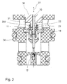
- Fig. 1 shows the variant Fig. 2 a varied control piece 21 and a modified embodiment of the core 30 with a (with respect to the axis of the control pin 20) concentric elevation 31st
- control piece 21 is also funnel-like or cone-like seen from the outside again.
- the functionality of the rule shown here is identical to that of Fig. 1 comparable and equivalent.
- the rule 21 has arisen in a plastic extrusion process, resulting in slightly larger wall thicknesses.
- the wall thickness itself is not the same everywhere, this can be realized by appropriate embodiments of the injection molding tool.
- fiber-reinforced plastic for example, carbon fiber or glass fiber reinforced plastic
- high temperature resistant plastic or high-strength plastic existing rule 21 is also provided on the control pin 20, an annular groove 24 or possibly other surface recesses, creating a positive connection between control pin 20th and Rule 21 is achieved.
- an elevation 31 facing the valve seat 11 is arranged concentrically around the bearing of the pin 20 in the core 30 on the core 30. Regardless of the axial position 27 of the pin 20 (and therefore of the control piece 21), this increase 31 is in the chamber 22 of the control piece 21 a. But there remains a small opening gap (annular) between the elevation 31 and the annular portion 202, through which also the medium to be controlled can flow. By this construction is achieved that there is a higher stability against pressure oscillations.
Landscapes
- Engineering & Computer Science (AREA)
- General Engineering & Computer Science (AREA)
- Mechanical Engineering (AREA)
- Magnetically Actuated Valves (AREA)
Abstract
Description
Die Erfindung betrifft ein durch einen Elektromagneten betätigbares Ventil, insbesondere Druckregelventil, wobei der Anker des Elektromagneten auf ein Regelelement des Ventils wirkt und dieses derart, insbesondere axial versetzt, dass sich die Spaltweite eines in beziehungsweise an einem Ventilelement, wie zum Beispiel einer Ventilplatte oder einer Ventilbuchse vorgesehenen Spaltes verändert beziehungsweise der Spalt sich öffnet oder schließt.The invention relates to an actuatable by an electromagnet valve, in particular pressure control valve, wherein the armature of the electromagnet acts on a control element of the valve and this so, in particular axially offset, that the gap width of a in or on a valve element, such as a valve plate or a Valve sleeve provided gap changed or the gap opens or closes.
Bei von Elektromagneten betätigten Druckregelventilen wird durch die Kraft des Elektromagneten der Spalt zwischen dem Regelelement und dem in der Ventilbuchse oder dem Ventilelement angeordneten Ventilsitz verändert und damit der Hydraulikdruck am Arbeitsanschluss gesteuert. Der Spalt ist begrenzt einerseits von dem Ventilsitz udn andererseits von der am Regelelement vorgesehenen Begrenzungsfläche. Da die Lage des Regelelements und daher der Begrenzungsfläche veränderlich ist, verändert sich auch der Abstand (Spaltweite) der den Spalt begrenzenden Flächen. Das Regelelement besteht dabei aus einem aus Metall gefertigten, üblicherweise gedrehten Regelstift, an dem einstückig eine entsprechede Abdichtfläche angearbeitet ist, die mit dem Ventilsitz zusammenwirkt. Der Elektromagnet besteht aus einer mit elektrischen Strom beaufschlagbaren Spule, welche einen Ankerraum umgibt. In dem Ankerraum ist ein auf das Regelelement wirkender Anker axial beweglich gelagert, dessen axiale Stellung durch die Bestromung der Spule veränderbar ist. Aufgrund dieser axialen Lageveränderung verändert sich die Spaltweite am Regelelement, natürlich ist dadurch auch ein Öffnen oder Schließen des Ventiles ebenfalls möglich.When actuated by solenoid pressure control valves, the gap between the control element and arranged in the valve sleeve or the valve element valve seat is changed and thus the hydraulic pressure by the force of the electromagnet controlled at the work connection. The gap is bounded on the one hand by the valve seat and on the other hand by the boundary surface provided on the control element. Since the position of the control element and therefore the boundary surface is variable, and the distance (gap width) of the gap limiting surfaces changed. The control element consists of a made of metal, usually rotated control pin, on which an appropriate sealing surface is integrally worked, which cooperates with the valve seat. The electromagnet consists of a coil which can be acted upon by electric current and which surrounds an armature space. In the armature space acting on the control element armature is mounted axially movable, the axial position can be changed by the energization of the coil. Due to this axial change in position, the gap width changes on the control element, of course, thereby opening or closing of the valve is also possible.
Die drehtechnische und daher zerspanende Herstellung des Regelelementes ist aufwendig.The rotary technical and therefore machining production of the control element is expensive.
Es ist daher das Ziel der Erfindung ein Ventil vorzuschlagen, welches günstiger herzustellen ist.It is therefore the object of the invention to propose a valve which is cheaper to produce.
Gelöst wird diese erfindungsgemäße Aufgabe durch ein Ventil, wie eingangs beschrieben, wobei vorgeschlagen wird, dass das Regelelement aus einem Regelstift und einem hiervon getrennt hergestellten, auf dem Regelstift befestigten Regelstück gebildet ist und das Regelstück mit dem Spalt zusammenwirkt.This object of the invention is achieved by a valve, as described above, wherein it is proposed that the control element from a control pin and a separately prepared, attached to the control pin control piece is formed and the control piece interacts with the gap.
Die Erfindung schlägt hier bewußt einen mehrteiligen Aufbau des Regelelementes vor, da der Bearbeitungsaufwand insbesondere für das Regelstück dadurch deutlich reduziert werden kann. Es ist nun möglich das Regelstück auf den jeweiligen Anwendungsfall zum Beispiel abhängig von Betriebsdruck, Medium, welches zu steuern ist usw., zu optimieren und für die Bewegung des Regelstückes immer den gleichen Regelstift zu verwenden. Es bleibt daher bei sehr hohen Losgrößen für standardisierte Regelstifte, die mit entsprechend optimierten Regelstücken verbunden werden. Der Spalt wird einerseits vom Ventilsitz und andererseits von der an dem Regelstück angeordneten Begrenzungsfläche begrenzt. Die Spaltweite definiert sich z. B. über den kürzesten Abstand zwischen dem Ventilsitz und der Begrenzungsfläche. Die Abdichtfläche ist dabei Teil der Begrenzungsfläche.The invention proposes deliberately a multi-part structure of the control element, since the processing cost can be significantly reduced in particular for the rule. It is now possible to optimize the control to the particular application, for example, depending on operating pressure, medium, which is to be controlled, etc., and for the movement of the control piece always use the same rule pin. It therefore remains at very high lot sizes for standardized control pins, which are connected to appropriately optimized control pieces. The gap is delimited on the one hand by the valve seat and on the other hand by the boundary surface arranged on the control element. The gap width is defined z. B. over the shortest distance between the valve seat and the boundary surface. The sealing surface is part of the boundary surface.
Regelstück und Regelstift werden dabei in geeigneter Weise miteinander verbunden, für ihre Materialpaarung bieten sich hier die verschiedensten Varianten an. Es können hier zum Beispiel Klebungen vorgesehen sein, es ist aber auch möglich, eine Verstemmung, ein Verschweißen oder eine sonstige formschlüssige oder kraftschlüssige Verbindungstechnik erfindungsgemäß einzusetzen. Da bewußt auch eine Materialungleichheit zwischen dem Regelstift und dem Regelstift von der Erfindung umfasst ist, geht die kostengünstigere Herstellung eines erfindungsgemäßen Ventiles einher mit einer höheren Ventildynamik, wenn nämlich für das Regelstück eine leichtere Bauform, z. B. mit einem Material geringer Dichte realisiert wird. Aufgrund des sich hier anbietenden Baukastenprinzips kann ein erfindungsgemäßes Druckregelventil, bei Verwendung des gleichen Regelstiftes, auch bezüglich seiner Ventildynamik durch Variation des jeweiligen Regelstückes auf die jeweilige Anwendung optimiert werden.Rule and control pin are connected to each other in a suitable manner, for their material pairing here offer a variety of variants. It can be provided here, for example, bonds, but it is also possible to use a caulking, welding or other form-fitting or non-positive connection technology according to the invention. Since deliberately a material inequality between the control pin and the control pin is encompassed by the invention, the cost-effective production of a valve according to the invention is accompanied by a higher valve dynamics, if for the rule a lighter design, eg. B. is realized with a material of low density. Due to the building block principle offered here, a pressure control valve according to the invention, when using the same control pin, can also be optimized with respect to its valve dynamics by varying the respective control piece to the respective application.
Dabei ist die Material- beziehungsweise Massenersparnis nicht nur aufgrund einer entsprechend unterschiedlichen Materialwahl von Regelstift und Regelstück begründet, grundsätzlich umfasst die Erfindung natürlich auch Anwendungen, bei welchen Regelstift und Regelstück materialgleich hergestellt sind, wobei aber zum Beispiel das Regelstück aus einem flächigen Material in einem Stanzbiege- oder Stanzsenkvorgang gewonnen worden ist, welcher in einer Massenfertigung äußerst kostengünstig realisierbar ist und dann aufgrund der geringen Wandstärke des Regelstückes zu einer entsprechenden Massenreduktion beiträgt, die Materialgleichheit lässt aber zum Beispiel ein Verschweißen des Regelstückes auf dem Regelstift zu!The material or mass savings is justified not only due to a correspondingly different choice of material rule pin and control piece, in principle, the invention, of course, includes applications in which rule pin and control are made the same material, but for example, the rule of a sheet material in a punch bend - Or punching lowering process has been obtained, which can be realized extremely inexpensively in a mass production is and then due to the small wall thickness of the rule contributes to a corresponding reduction in mass, but the material equality allows, for example, a welding of the control piece on the rule pin!
In der Anmeldung wird der Begriff Ventilplatte oder Ventilbuchse als beispielhafte Ausgestaltung des Ventilelementes beschrieben. Soweit ein Merkmal nur für das Merkmal der Ventilbuchse oder der Ventilplatte verwendet worden ist, beziehungsweise hier definiert ist, so beschränkt dies die Erfindung in diesem Bereich nicht. Anstelle der Bezeichnung Ventilbuchse oder Ventilplatte ist allgemein auch der Begriff Ventilelement zu setzen.In the application, the term valve plate or valve sleeve is described as an exemplary embodiment of the valve element. As far as a feature has been used only for the feature of the valve sleeve or the valve plate, or as defined here, this does not limit the invention in this area. Instead of the term valve bushing or valve plate is generally also the term valve element set.
Die Erfindung ist in gleicher Weise auch bei Ventilen, insbesondere Druckregelventilen anwendbar, bei welchen der Anker direkt oder indirekt auf das Regelelement wirkt. Bei einer indirekten Anordnung ist zum Beispiel zwischen dem Anker und dem Regelelement ein Zwischenstück vorgesehen, was gegebenenfalls auch fliegend, wie auch das Regelelement, gelagert ist. Eine Rückstellung oder Anlage wird zum Beispiel durch entsprechende Rückstellfeder oder ähnlichem erreicht. Natürlich ist es erfindungsgemäß auch vorgesehen, dass das Regelelement, insbesondere der Regelstift, fest (und somit zum Beispiel direkt) mit dem Anker verbunden ist. Beide vorgenannten Varianten gehören zur Erfindung.The invention is equally applicable to valves, in particular pressure control valves, in which the armature acts directly or indirectly on the control element. In an indirect arrangement, for example, between the armature and the control element, an intermediate piece is provided, which optionally also flying, as well as the control element, is mounted. A provision or investment is achieved for example by appropriate return spring or the like. Of course, it is also provided according to the invention that the control element, in particular the control pin, fixed (and thus for example directly) is connected to the anchor. Both aforementioned variants are part of the invention.
Bezüglich der Ausgestaltung des Regelstückes ist die Erfindung ebenfalls sehr variabel einsetzbar. Es ist möglich, dass das Regelstück scheiben-, teller-, kegel-, trichter- oder konusartig ausgebildet ist, wobei sich die Realisierungsmöglichkeiten des Regelstückes auf diese Varianten nicht beschränkt. So ist es zum Beispiel möglich, dass auch ringscheibenartige Regelstücke und so weiter verwendet werden. Natürlich ist die entsprechende Wahl des Regelstückes auf den Anwendungsfall und auf die Ausgestaltung der Ventilbuchse, insbesondere des Ventilsitzes abzustimmen, weswegen sich die unterschiedlichen Typen von Regelstücken auf die jeweiligen Anwendungsfälle beziehen.With respect to the design of the control piece, the invention is also very variable. It is possible that the control piece is disc-shaped, plate-shaped, conical, funnel-shaped or cone-shaped, with the realization possibilities of the regulating piece not being limited to these variants. For example, it is also possible to use ring-disk-like control pieces and so on. Of course, the appropriate choice of the rule on the application and on the design of the valve sleeve, in particular the valve seat why the different types of control are related to the respective application.
Es ist gefunden worden, dass trichter-, kegel- oder konusartige Regelstücke, gerade bei schnell schaltenden Ventilen beziehungsweise schnell steuernden Druckregelventilen Vorteile aufweisen, die sie neben der durch die Massenreduzierung begründete höhere Ventildynamik auch eine höhere Stabilität gegen Druckschwingungen, aufgrund der kegel-, konus- oder trichterartigen Ausgestaltung aufweisen. Daher besitzt dann das Regelstück rückseitig eine zugängliche Kammer, wie diese auch in den Zeichnungen (siehe Bezugszeichen 22) gezeigt ist.It has been found that funnel, conical or cone-like control pieces, especially in fast-switching valves or rapidly controlling pressure control valves have advantages that they in addition to the mass reduction due to the higher valve dynamics also higher stability against pressure oscillations, due to the conical, conical - or funnel-like configuration. Therefore, then has the rule back an accessible chamber, as shown in the drawings (see reference numeral 22) is shown.
Die konusartige Ausgestaltung weist des Weiteren eine strömungsgünstige Formgebung auf, die das zu steuernde Medium in geeigneter Weise, der Konusmantelfläche folgend, ablenkt. Durch eine solche Formgebung wird auch bei hohen Drücken eine möglichst laminare Strömung beibehalten und Strömungsverluste entsprechend vermieden.The conical design further has a streamlined shape, which deflects the medium to be controlled in a suitable manner, following the conical surface. By means of such shaping, a flow which is as laminar as possible is maintained even at high pressures and flow losses are correspondingly avoided.
In einer bevorzugten Ausgestaltung der Erfindung ist das Regelstück dünnwandig ausgebildet. Die Stärke der das Regelstück begrenzenden Wand ist dabei deutlich geringer wie der Durchmesser des Regelstiftes beziehungsweise dessen Radius. Neben einer relativen Definition des Begriffes "dünnwandig" bezogen auf andere Dimensionen des erfindungsgemäßen Ventils kann die Dünnwandigkeit aber auch beispielhaft (und daher nicht begrenzend) mit einer Wandstärke von weniger als 2 mm, insbesondere weniger als 1 mm, bevorzugt weniger als 5/10 mm oder 8/10 mm beschrieben werden. Die richtige Wandstärke ergibt sich insbesondere aus dem Anwendungsbereich der Erfindung. Es ist klar, dass eine entsprechend geringe Materialdicke auch zu einer geringeren Masse und daher zu einer entsprechenden Ventildynamik beiträgt. Dabei ist zu beachten, dass die dünnwandige Ausgestaltung des Regelstückes sowohl bei Scheiben, Ringscheibenteller oder auch kegel- oder konusartig ausgebildeten Regelstücken einsetzbar ist. Diese erfindungsgemäße Variante ist dabei auch nicht nur auf die spezielle Materialwahl des Regelstückes beschränkt, das Regelstück ist aus Metall, zum Beispiel Leichtmetall, Aluminium oder auch nichtmagnetisierbaren oder unmagnetisierbaren Metallen beziehungsweise Stählen realisierbar.In a preferred embodiment of the invention, the control piece is formed thin-walled. The strength of the wall limiting the rule is much smaller than the diameter of the rule pin or its radius. In addition to a relative definition of the term "thin-walled" with respect to other dimensions of the valve according to the invention, the thin-walledness can also be exemplary (and therefore not limiting) with a wall thickness of less than 2 mm, in particular less than 1 mm, preferably less than 5/10 mm or 8/10 mm. The right wall thickness results in particular from the scope of the invention. It is clear that a correspondingly small material thickness also contributes to a lower mass and therefore to a corresponding valve dynamics. It should be noted that the thin-walled design of the control piece can be used both in discs, washer discs or conical or cone-shaped control pieces. This variant of the invention is not limited to the specific choice of material of the rule, the rule is made of metal, for example, light metal, aluminum or non-magnetizable or non-magnetizable metals or steels feasible.
Neben einer dünnwandigen Ausgestaltung des Regelstückes umfasst die Erfindung aber auch Varianten, bei welchen ein kegel- oder konusartiges Regelstück, zum Beispiel aus Vollmaterial, gebildet ist.In addition to a thin-walled design of the control piece, however, the invention also includes variants in which a conical or cone-like control piece, for example of solid material, is formed.
In einer bevorzugten Variante ist das Regelstück durch eine Kammer gekennzeichnet beziehungsweise die verhältnismäßig dünnwandige Begrenzungswand des Regelstückes umschließt eine Kammer, die rückseitig, der Konusspitze abgeneigt, zugänglich ist. Dabei ist üblicherweise das Regelstück mit seiner Konus- oder Kegelspitze mit dem Regelstift verbunden, derart, dass der Regelstift das Regelstück durchdringt und eigentlich die Ausgestaltung des Regelstückes in diesem Bereich kegelstumpfartig ist, was aber im Sinne der Erfindung mit kegel-, trichter- oder konusartig als umschrieben anzusehen ist. Aufgrund der kegelbeziehungsweise konusartigen Ausgestaltung verläuft die (äußere) Begrenzungswand des Regelstückes in einem spitzen Winkel zur Längsachse des Regelstiftes und es bildet sich so eine Kammer, die auch von dem Medium, welches zu steuern beziehungsweise zu regeln ist, befüllt ist.In a preferred variant, the control piece is characterized by a chamber or the relatively thin-walled boundary wall of the control piece encloses a chamber, the back, the cone tip is averse, accessible. In this case, usually the rule is connected with its conical or conical tip with the rule pin, such that the rule pin penetrates the rule and actually the design of the rule in this area is frustoconical, but what in the context of the invention with conical, funnel or cone-like is to be regarded as circumscribed. Due to the cone-like cone-like configuration, the (outer) boundary wall of the control piece runs at an acute angle to the longitudinal axis of the control pin and it thus forms a chamber which is also filled by the medium which is to be controlled or regulated.
In einer bevorzugten Ausgestaltung der Erfindung ist vorgesehen, dass in dem Verbindungsbereich von Regelstück und Regelstift auf dem Regelstift eine Umfangsnut oder Oberflächenausnehmung vorgesehen ist, die von dem Material des Regelstückes ausgefüllt ist. Durch das Einarbeiten einer entsprechenden Umfangsnut oder einer Oberflächenausnehmung in den Regelstift wird bei dem Verbindungsvorgang des Regelstückes auf dem Regelstift Material eingepresst und so ein formschlüssiger Verbund hergestellt. Dabei wird die Umfangsnut beziehungsweise die Oberflächenausnehmung nicht nur von einem metallischen Werkstoff des Regelstückes ausgefüllt, das Regelstück kann auch zum Beispiel aus Kunststoff bestehen und in einem Kunststoffspritzvorgang auf dem Regelstift angeordnet werden, wobei auch dann der (noch flüssige) Kunststoff die Umfangsnut oder eine entsprechende Oberflächenausnehmung ausfüllt.In a preferred embodiment of the invention it is provided that in the connection region of the control piece and control pin on the control pin a circumferential groove or surface recess is provided, which is filled by the material of the control piece. By incorporating a corresponding circumferential groove or a surface recess in the control pin is pressed in the connection process of the rule on the rule pin material and so produced a positive connection. In this case, the circumferential groove or the surface recess is not only filled by a metallic material of the control piece, the control piece may also be made of plastic, for example, and be arranged in a plastic injection process on the control pin, in which case the (still liquid) plastic the circumferential groove or a corresponding Surface recess fills.
Der grundsätzlich zweiteilige Aufbau des Regelelementes in Regelstift und Regelstück ermöglicht es, dass Regelstift und Regelstück auch aus unterschiedlichen Materialien bestehen, wenngleich die Variante, beide aus gleichen Materialien herzustellen, ebenso zur Erfindung zählt (z. B. Metall mit Metall oder Kunststoff mit Kunststoff). Regelstück beziehungsweise Regelstift können daher zum Beispiel aus Kunststoff, faserverstärktem Kunststoff, hochtemperaturfestem Kunststoff, hochfestem Kunststoff oder Metall, insbesondere un- oder geringmagnetischem Metall, wie entsprechende Stähle und so weiter, gebildet sein. Das Regelstück ist darüber hinaus alternativ zum Beispiel auch aus einer Metallfolie oder einem dünnwandigen Metallteil gebildet, es kann alternativ auch aus Keramik bestehen.The basically two-part construction of the control element in control pin and control piece makes it possible that control pin and control piece also consist of different materials, although the variant, both of the same materials, also belongs to the invention (eg metal with metal or plastic with plastic) , Control piece or regulating pin can therefore be formed, for example, from plastic, fiber-reinforced plastic, high-temperature-resistant plastic, high-strength plastic or metal, in particular non-magnetic or low-magnetic metal, such as corresponding steels and so on. The rule is also formed, for example, alternatively, for example, from a metal foil or a thin-walled metal part, it may alternatively be made of ceramic.
Gerade die Verwendung von neuartigen Hochtemperaturpolymeren mit einer Schmelztemperatur von über 380°C und einer Glasübergangstemperatur von mindestens 150°C erlauben es, kostengünstige hochtemperaturfeste und leichte Regelstücke zur Verfügung zu stellen, und somit auch noch extremere Anwendungsbereiche von erfindungsgemäßen Ventilen, insbesondere Druckregelventilen, zuverlässig zu beherrschen.Especially the use of novel high-temperature polymers having a melting temperature of about 380 ° C and a glass transition temperature of at least 150 ° C make it possible to provide cost-effective high temperature resistant and lightweight control pieces, and thus even more extreme applications of valves according to the invention, especially pressure control valves reliably dominate.
In einer bevorzugten Variante der Erfindung ist vorgesehen, dass der Regelstift in einem dem Kern geführt beziehungsweise gelagert ist und der Kern eine, dem Regelstück zugewandte Erhöhung aufweist, welche zumindest bei axialer Rückzugsbewegung des Regelstiftes zumindest teilweise in die Kammer eintaucht. In diesem Ausführungsbeispiel, wie es auch in der Zeichnung gezeigt ist (vergleiche
Die Erfindung umfasst gleichwohl aber auch eine Lösung, bei welcher eine einstückige Variante des Regelelementes zum Beispiel aus Kunststoff oder Metall gefertigt wird. Als Material für die einstückige Ausführung des Regelelementes kommen dabei alle Materialien, die in dieser Anmeldung beschrieben sind, in Frage, also zum Beispiel Kunststoff, faserverstärkter Kunststoff, hochtemperaturfester Kunststoff, hochfester Kunststoff, Metall, insbesondere un- oder geringmagnetisches Metall, dünnwandiges Metall, Blech oder Folie beziehungsweise Keramik. Allgemein finden hierbei zum Beispiel entsprechende Stähle Verwendung, es ist aber auch möglich, zum Beispiel Kupfer, Aluminium oder andere Metalle, im Sinne der Erfindung einzusetzen. Die vorgenannte Metallwahl bezieht sich dabei auf alle Anwendungsfälle dieser Erfindung beziehungsweise dieser Anmeldung.However, the invention nevertheless also includes a solution in which a one-piece variant of the control element is produced, for example, from plastic or metal. As a material for the one-piece design of the control element while all the materials described in this application come into question, ie for example plastic, fiber reinforced plastic, high temperature resistant plastic, high strength plastic, metal, especially un-or low magnetic metal, thin-walled metal, sheet metal or foil or ceramic. In general, for example, corresponding steels are used, but it is also possible to use, for example, copper, aluminum or other metals in the context of the invention. The aforementioned metal choice refers to all applications of this invention or this application.
Es ist dabei auch möglich, ein einstückiges Regelelement aus metallischen Werkstoffen, zum Beispiel durch Drehen oder im geeigneten Verfahren wie zum Beispiel Ziehen und Falten herzustellen. Es ist auch grundsätzlich möglich, dass bei Materialgleichheit von Regelelement und Regelstück die beiden getrennt hergestellten Elemente hernach zum Beispiel verschweißt werden und so definitionsgemäß einstückig sind (aufgrund Materialgleichheit und der materialgleichen Verbindung), aber trotzdem der erfindungsgemäße Vorteil bei der Herstellung erhalten wurde.It is also possible to produce a one-piece control element of metallic materials, for example by turning or in a suitable method such as drawing and folding. It is also possible in principle that the material equality of control element and control element, the two separately produced elements are welded, for example, and are thus by definition one piece (due to material equality and the same material connection), but still the advantage of the invention was obtained in the production.
In der Zeichnung ist die Erfindung insbesondere in einem Ausführungsbeispiel schematisch dargestellt. Es zeigen:
- Fig. 1, 2 und 3
- je in einer Schnittdarstellung verschiedene Varianten des erfin- dungsgemäßen Ventils.
- Fig. 1, 2 and 3
- each in a sectional view different variants of the inventive valve.
In den Figuren sind gleiche oder einander entsprechende Elemente jeweils mit den gleichen Bezugszeichen bezeichnet und werden daher, sofern nicht zweckmäßig, nicht erneut beschrieben.In the figures, the same or corresponding elements are denoted by the same reference numerals and therefore, if not appropriate, will not be described again.
Das erfindungsgemäße Ventil 1 ist in den Figuren in verschiedenen Varianten schematisch dargestellt. Das dargestellte Ventil 1 wird durch einen nicht dargestellten Elektromagneten, der aber ebenfalls zur Erfindung zählt, betätigt beziehungsweise gesteuert. Üblicherweise besteht ein Elektromagnet aus einem in einem Ankerraum beweglich gelagerten Anker, der auf den Regelstift 20 wirkt. Der Ankerraum ist umgeben von einer mit elektrischen Strom beaufschlagbaren Spule, die ein entsprechendes Magnetfeld erzeugt. Entsprechend des erzeugten Magnetfeldes wird der Anker axial versetzt, wodurch auch der Regelstift 20 eine axiale Versetzung erfährt.The
Dabei ist der Regelstift 20 ein Teil des Regelelementes 2.In this case, the
Der Elektromagnet würde sich oberhalb des Ventiles 1 anschließen, der Regelstift 20 ist in dem Kern 30 in geeigneter Weise gelagert beziehungsweise geführt.The electromagnet would connect above the
Das in der Zeichnung gezeigte Ventil 1 ist insbesondere als Druckregelventil ausgebildet. Dabei umfasst das Ventil 1 eine Ventilbuchse 15, in welcher ein Ventilsitz 11 vorgesehen ist. In dem hier gezeigten Ausführungsbeispiel ist der Ventilsitz 11 realisiert durch einen Träger 18 mit zentrischer Durchdringungsöffnung 17 und sich darunter anschließenden Führungskäfig 16.The
Mit dem Doppelpfeil 27 ist die axiale Verstellbarkeit des Regelelementes 2 angedeutet. Aufgrund der konischen Ausgestaltung des Regelstückes 21 wird klar, dass das Regelstück 21 die in dem Ventilsitz 11 vorgesehene Öffnung 17 je nach axialer Stellung (27) des Regelstückes mehr oder weniger freigibt, das heißt, den Spalt 10 vergrößert oder verkleinert.With the
In den in den
Ein wesentlicher Bestandteil der Erfindung ist, dass das Regelelement 2 zweiteilig ausgebildet ist, also einen Regelstift 20 und ein davon getrennt hergestelltes, gegebenenfalls aus gleichen oder unterschiedlichen Materialien bestehendes Regelstück 21 aufweist. Für eine exakte aber auch mechanisch stabile Verbindung ist auf dem Regelstift 20 an geeigneter Stelle eine Umfangsnut 24 vorgesehen, in die, entsprechend dem Verbindungsverfahren von Regelstück 21 auf Regelstift 20, Material des Regelstückes 21 eindringt. Hierdurch ist es möglich, einen formschlüssigen Verbund zwischen dem Regelstück 21 und dem Regelstift 20 zu realisieren, der mechanisch stark belastbar ist.An essential component of the invention is that the
Wie in den Zeichnungen dargestellt, ist das Regelstück 21 nicht am Ende des Regelstiftes 20 vorgesehen, sondern es besteht noch ein gewisser Überstand 26 unterhalb des Verbindungsbereiches 28, der natürlich die Umfangsnut 24 umfasst. Mit Hilfe dieses Überstandes 26 werden weitere Regelteile 12 des Ventiles 1 für verschiedene Zwecke angesteuert. Unterhalb des Trägers 18 schließt sich der Führungskäfig 16 an, der für eine Führung des Überstandes 26 des Regelstiftes dient. In dem hier gezeigten Ausführungsbeispiel ist zum Beispiel eine Kugel 19 in einem Käfig derart gehalten, dass es durch die Betätigung des Regelstiftes 20 beziehungsweise Überstandes 26 nur nach unten verschoben werden kann und dann einen entsprechenden Durchlass freigibt. Dabei ist die Kugel 19 lose, also getrennt von dem Regelstift 20.As shown in the drawings, the
Das Regelstück 21 besitzt eine Abdichtfläche 25. Diese Abdichtfläche 25 ist Teil der äußeren Begrenzungsfläche beziehungsweise Manteloberfläche des konusartig oder kegelartig realisierten Regelstückes 21. Ein gewisser Bereich der Begrenzungswand 23, die verhältnismäßig dünnwandig ist, liegt im komplett geschlossenen Zustand des Ventils als Abdichtfläche 25 auf dem Ventilsitz 11 auf und verschließt den Spalt 10 völlig. Dabei beträgt die Materialstärke der dünnwandigen Begrenzungswand 23 weniger als 1,5 mm, bevorzugt weniger als 1,0 mm, insbesondere weniger als 800 µm. Bezogen auf den Durchmesser des Regelstiftes ist die Wandstärke weniger als 50%, bevorzugt weniger als 35%, insbesondere weniger als 30%.This sealing
Das in
Dabei ist die Kammer 22 auf der dem Ventilsitz 11 abgewandten Seite zugänglich und in geeigneter Weise von dem zu steuernden Medium durchströmt.In this case, the
Es ist gut zu erkennen, dass die Ausgestaltung des Regelstückes 21 nach
Das Regelstück 21 weitet sich dann von der Engstelle 201 nach oben konus- oder trichterartig aus und schließt dann mit einem Ring 202 mit konstantem Radius ab. Die Oberkante des Ringes 202 bildet auch den Abschluss des Regelstückes 21 und begrenzt die Kammer 22.The
Im Gegensatz zu dem Vorschlag nach
Die in
In dem hier gezeigten Ausführungsbeispiel ist an dem Kern 30 eine, dem Ventilsitz 11 zugewandte Erhöhung 31 konzentrisch um die Lagerung des Stiftes 20 in dem Kern 30 angeordnet. Unabhängig von der axialen Stellung 27 des Stiftes 20 (und daher des Regelstückes 21), steht diese Erhöhung 31 in die Kammer 22 des Regelstückes 21 ein. Dabei bleibt aber ein kleiner Öffnungsspalt (ringförmig) zwischen der Erhöhung 31 und dem ringartigen Abschnitt 202, durch welchen auch das zu steuernde Medium strömen kann. Durch diese Konstruktion wird erreicht, dass eine höhere Stabilität gegen Druckschwingungen besteht.In the exemplary embodiment shown here, an
Der Vorschlag nach
Die jetzt mit der Anmeldung und später eingereichten Ansprüche sind Versuche zur Formulierung ohne Präjudiz für die Erzielung weitergehenden Schutzes.The claims now filed with the application and later are attempts to formulate without prejudice to the attainment of further protection.
Sollte sich hier bei näherer Prüfung, insbesondere auch des einschlägigen Standes der Technik, ergeben, daß das eine oder andere Merkmal für das Ziel der Erfindung zwar günstig, nicht aber entscheidend wichtig ist, so wird selbstverständlich schon jetzt eine Formulierung angestrebt, die ein solches Merkmal, insbesondere im Hauptanspruch, nicht mehr aufweist.If, on closer examination, in particular also of the relevant prior art, it appears that one or the other feature is beneficial for the purpose of the invention, but not of decisive importance, it is of course already desired to formulate such a feature , in particular in the main claim, no longer having.
Es ist weiter zu beachten, daß die in den verschiedenen Ausführungsformen beschriebenen und in den Figuren gezeigten Ausgestaltungen und Varianten der Erfindung beliebig untereinander kombinierbar sind. Dabei sind einzelne oder mehrere Merkmale beliebig gegeneinander austauschbar. Diese Merkmalskombinationen sind ebenso mit offenbart.It should further be noted that the embodiments and variants of the invention described in the various embodiments and shown in the figures can be combined with one another as desired. Here, one or more features are arbitrarily interchangeable. These feature combinations are also disclosed with.
Die in den abhängigen Ansprüchen angeführten Rückbeziehungen weisen auf die weitere Ausbildung des Gegenstandes des Hauptanspruches durch die Merkmale des jeweiligen Unteranspruches hin. Jedoch sind diese nicht als ein Verzicht auf die Erzielung eines selbständigen, gegenständlichen Schutzes für die Merkmale der rückbezogenen Unteransprüche zu verstehen.The references cited in the dependent claims indicate the further development of the subject matter of the main claim by the features of the respective subclaim. However, these are not to be understood as a waiver of obtaining independent, objective protection for the features of the dependent claims.
Merkmale, die bislang nur in der Beschreibung offenbart wurden, können im Laufe des Verfahrens als von erfindungswesentlicher Bedeutung, zum Beispiel zur Abgrenzung vom Stand der Technik beansprucht werden.Features that have hitherto been disclosed only in the description may be claimed in the course of the method as of essential importance to the invention, for example to distinguish from the prior art.
Merkmale, die nur in der Beschreibung offenbart wurden, oder auch Einzelmerkmale aus Ansprüchen, die eine Mehrzahl von Merkmalen umfassen, können jederzeit zur Abgrenzung vom Stande der Technik in den ersten Anspruch übernommen werden, und zwar auch dann, wenn solche Merkmale im Zusammenhang mit anderen Merkmalen erwähnt wurden beziehungsweise im Zusammenhang mit anderen Merkmalen besonders günstige Ergebnisse erreichen.Features which have been disclosed only in the description, or also individual features of claims comprising a plurality of features, may at any time be included in the first claim for distinction from the prior art, even if such features are associated with others Characteristics were mentioned or achieve particularly favorable results in connection with other features.
Claims (14)
Applications Claiming Priority (1)
| Application Number | Priority Date | Filing Date | Title |
|---|---|---|---|
| DE102009035902 | 2009-08-03 |
Publications (2)
| Publication Number | Publication Date |
|---|---|
| EP2282090A2 true EP2282090A2 (en) | 2011-02-09 |
| EP2282090A3 EP2282090A3 (en) | 2013-11-20 |
Family
ID=42830711
Family Applications (1)
| Application Number | Title | Priority Date | Filing Date |
|---|---|---|---|
| EP20100008045 Withdrawn EP2282090A3 (en) | 2009-08-03 | 2010-08-02 | Valve, in particular pressure regulating valve |
Country Status (3)
| Country | Link |
|---|---|
| US (1) | US9103462B2 (en) |
| EP (1) | EP2282090A3 (en) |
| DE (1) | DE102010033032A1 (en) |
Families Citing this family (2)
| Publication number | Priority date | Publication date | Assignee | Title |
|---|---|---|---|---|
| DE102013107390B4 (en) * | 2013-07-12 | 2023-06-07 | Svm Schultz Verwaltungs-Gmbh & Co. Kg | Pressure control valve with control element |
| DE102013220877A1 (en) * | 2013-10-15 | 2015-04-16 | Continental Automotive Gmbh | Valve |
Family Cites Families (13)
| Publication number | Priority date | Publication date | Assignee | Title |
|---|---|---|---|---|
| US788536A (en) * | 1903-03-14 | 1905-05-02 | John Patrick O Donnell | Pneumatic railway signaling system and electropneumatic valve therefor. |
| US2283903A (en) * | 1940-04-29 | 1942-05-26 | Honeywell Regulator Co | Valve |
| US2521308A (en) * | 1945-12-22 | 1950-09-05 | Louis M Porter | Vent structure for incubators |
| US2612188A (en) * | 1947-04-11 | 1952-09-30 | Mcquay Norris Mfg Co | Solenoid-operated gas valve |
| US3955795A (en) * | 1973-11-15 | 1976-05-11 | Refreshment Machinery Incorporated | Valve |
| US4304258A (en) * | 1979-10-15 | 1981-12-08 | The Garrett Corporation | Solenoid valve assembly |
| US5526837A (en) * | 1994-12-01 | 1996-06-18 | Robertshaw Controls Company | Solenoid controlled one-way valve |
| DE10023329A1 (en) * | 2000-05-12 | 2001-11-15 | Bosch Gmbh Robert | Valve has housing with inlet and outlet ducts, lifting rod opening into actuator, connecting pipe and valve element. |
| DE10023582A1 (en) * | 2000-05-13 | 2001-11-15 | Bosch Gmbh Robert | Valve has chamber with inlet and outlet ducts, lifting rod, actuator, valve element, and valve seating |
| DE10351504A1 (en) * | 2003-11-05 | 2005-06-02 | Robert Bosch Gmbh | Electromagnetic pressure control valve for force flow has a magnetic part with an electrically triggered coil, a coil core, a sliding armature and a valve part |
| DE102005059433A1 (en) * | 2005-12-13 | 2007-06-14 | Robert Bosch Gmbh | Electromagnetic pressure control valve for use in automatic drive of motor vehicle, has transmission unit receiving anchor of magnet part and guided into bearing body that is made of plastic material and that is embedded into pole core |
| DE102007035472A1 (en) * | 2007-07-26 | 2009-01-29 | Svm Schultz Verwaltungs-Gmbh & Co. Kg | Valve |
| DE102009004803A1 (en) * | 2008-01-17 | 2009-07-23 | Eto Magnetic Gmbh | Electromagnetically actuated valve device |
-
2010
- 2010-08-02 DE DE102010033032A patent/DE102010033032A1/en not_active Withdrawn
- 2010-08-02 EP EP20100008045 patent/EP2282090A3/en not_active Withdrawn
- 2010-08-03 US US12/805,507 patent/US9103462B2/en active Active
Non-Patent Citations (1)
| Title |
|---|
| None |
Also Published As
| Publication number | Publication date |
|---|---|
| US9103462B2 (en) | 2015-08-11 |
| DE102010033032A1 (en) | 2011-02-10 |
| US20110042596A1 (en) | 2011-02-24 |
| EP2282090A3 (en) | 2013-11-20 |
Similar Documents
| Publication | Publication Date | Title |
|---|---|---|
| EP2308064B1 (en) | Solenoid arrangement and valve arrangement | |
| EP3206214B1 (en) | Electromagnetic device, and driver assistance device | |
| DE102012106134A1 (en) | Valve | |
| EP2759749A1 (en) | Electromagnetic fluid valve | |
| DE102005023547A1 (en) | Electrically controllable valve | |
| EP2405167A2 (en) | Electromagnetic valve for a combustion engine | |
| DE102008043798A1 (en) | Fuel metering unit for a fuel pump | |
| EP3358233B1 (en) | Valve, in particular spool valve | |
| AT510989B1 (en) | FLOW CONTROL DEVICE | |
| EP3446013B1 (en) | Electromagnetically operable valve device | |
| EP2282090A2 (en) | Valve, in particular pressure regulating valve | |
| EP2853792B2 (en) | Device for regulating the flow of a fluid | |
| EP2299458B1 (en) | Electromagnet | |
| DE102007035472A1 (en) | Valve | |
| DE102013107390B4 (en) | Pressure control valve with control element | |
| DE102007006871B4 (en) | Ball seat valve with funnel-shaped expanding valve seat body | |
| EP1734541A2 (en) | Electromagnet with control cone | |
| WO2013056958A1 (en) | Method for producing a magnetic separation for a solenoid valve | |
| WO2016058773A1 (en) | Fuel injection valve | |
| EP3312853A1 (en) | Electromagnet | |
| EP4031786A1 (en) | Solenoid valve for a motor vehicle and method for producing a movement unit from an armature and a valve unit for a solenoid valve of this kind | |
| DE102013107389B4 (en) | pressure control valve | |
| EP3545185B1 (en) | Gas dosing valve | |
| DE10321154A1 (en) | Valve | |
| WO2020020836A1 (en) | Valve |
Legal Events
| Date | Code | Title | Description |
|---|---|---|---|
| PUAI | Public reference made under article 153(3) epc to a published international application that has entered the european phase |
Free format text: ORIGINAL CODE: 0009012 |
|
| AK | Designated contracting states |
Kind code of ref document: A2 Designated state(s): AL AT BE BG CH CY CZ DE DK EE ES FI FR GB GR HR HU IE IS IT LI LT LU LV MC MK MT NL NO PL PT RO SE SI SK SM TR |
|
| AX | Request for extension of the european patent |
Extension state: BA ME RS |
|
| PUAL | Search report despatched |
Free format text: ORIGINAL CODE: 0009013 |
|
| AK | Designated contracting states |
Kind code of ref document: A3 Designated state(s): AL AT BE BG CH CY CZ DE DK EE ES FI FR GB GR HR HU IE IS IT LI LT LU LV MC MK MT NL NO PL PT RO SE SI SK SM TR |
|
| AX | Request for extension of the european patent |
Extension state: BA ME RS |
|
| RIC1 | Information provided on ipc code assigned before grant |
Ipc: F16K 31/06 20060101AFI20131011BHEP |
|
| STAA | Information on the status of an ep patent application or granted ep patent |
Free format text: STATUS: THE APPLICATION IS DEEMED TO BE WITHDRAWN |
|
| 18D | Application deemed to be withdrawn |
Effective date: 20140521 |