EP2282063A1 - Ensemble formé d'un support-moteur et d'une bague de réception de ce dernier - Google Patents
Ensemble formé d'un support-moteur et d'une bague de réception de ce dernier Download PDFInfo
- Publication number
- EP2282063A1 EP2282063A1 EP10167380A EP10167380A EP2282063A1 EP 2282063 A1 EP2282063 A1 EP 2282063A1 EP 10167380 A EP10167380 A EP 10167380A EP 10167380 A EP10167380 A EP 10167380A EP 2282063 A1 EP2282063 A1 EP 2282063A1
- Authority
- EP
- European Patent Office
- Prior art keywords
- motor
- assembly
- ring
- motor support
- volute
- Prior art date
- Legal status (The legal status is an assumption and is not a legal conclusion. Google has not performed a legal analysis and makes no representation as to the accuracy of the status listed.)
- Granted
Links
Images


Classifications
-
- F—MECHANICAL ENGINEERING; LIGHTING; HEATING; WEAPONS; BLASTING
- F04—POSITIVE - DISPLACEMENT MACHINES FOR LIQUIDS; PUMPS FOR LIQUIDS OR ELASTIC FLUIDS
- F04D—NON-POSITIVE-DISPLACEMENT PUMPS
- F04D25/00—Pumping installations or systems
- F04D25/02—Units comprising pumps and their driving means
- F04D25/08—Units comprising pumps and their driving means the working fluid being air, e.g. for ventilation
-
- F—MECHANICAL ENGINEERING; LIGHTING; HEATING; WEAPONS; BLASTING
- F04—POSITIVE - DISPLACEMENT MACHINES FOR LIQUIDS; PUMPS FOR LIQUIDS OR ELASTIC FLUIDS
- F04D—NON-POSITIVE-DISPLACEMENT PUMPS
- F04D29/00—Details, component parts, or accessories
- F04D29/08—Sealings
- F04D29/083—Sealings especially adapted for elastic fluid pumps
-
- F—MECHANICAL ENGINEERING; LIGHTING; HEATING; WEAPONS; BLASTING
- F04—POSITIVE - DISPLACEMENT MACHINES FOR LIQUIDS; PUMPS FOR LIQUIDS OR ELASTIC FLUIDS
- F04D—NON-POSITIVE-DISPLACEMENT PUMPS
- F04D29/00—Details, component parts, or accessories
- F04D29/60—Mounting; Assembling; Disassembling
- F04D29/601—Mounting; Assembling; Disassembling specially adapted for elastic fluid pumps
-
- F—MECHANICAL ENGINEERING; LIGHTING; HEATING; WEAPONS; BLASTING
- F04—POSITIVE - DISPLACEMENT MACHINES FOR LIQUIDS; PUMPS FOR LIQUIDS OR ELASTIC FLUIDS
- F04D—NON-POSITIVE-DISPLACEMENT PUMPS
- F04D29/00—Details, component parts, or accessories
- F04D29/60—Mounting; Assembling; Disassembling
- F04D29/64—Mounting; Assembling; Disassembling of axial pumps
- F04D29/644—Mounting; Assembling; Disassembling of axial pumps especially adapted for elastic fluid pumps
- F04D29/646—Mounting or removal of fans
-
- F—MECHANICAL ENGINEERING; LIGHTING; HEATING; WEAPONS; BLASTING
- F01—MACHINES OR ENGINES IN GENERAL; ENGINE PLANTS IN GENERAL; STEAM ENGINES
- F01N—GAS-FLOW SILENCERS OR EXHAUST APPARATUS FOR MACHINES OR ENGINES IN GENERAL; GAS-FLOW SILENCERS OR EXHAUST APPARATUS FOR INTERNAL-COMBUSTION ENGINES
- F01N2470/00—Structure or shape of exhaust gas passages, pipes or tubes
- F01N2470/02—Tubes being perforated
Definitions
- the invention is in the field of ventilation, heating and / or air conditioning equipment equipping a motor vehicle. It relates to an assembly formed of a motor support and a receiving ring of the motor support. It also relates to a motor-fan unit consisting of the engine mount, the engine and a turbine rotated by the engine. It also relates to a volute provided with such a ring. It also relates to a blower comprising such a fan motor group and such a volute. Finally, it relates to a method of assembly and disassembly of such a set.
- a motor vehicle is commonly equipped with a ventilation, heating and / or air conditioning system to modify the aerothermal parameters of the air contained inside the passenger compartment of the vehicle. This modification is obtained from the delivery of an air flow inside the passenger compartment.
- the installation consists mainly of a housing that is made of plastic and is housed under a dashboard of the vehicle. The installation is provided with at least one inlet of the flow of air inside the housing and at least one outlet of the air flow out of the housing to the passenger compartment.
- the installation houses a blower to generate the flow of air and circulate it from the intake mouth to the delivery port.
- the blower includes a volute on which is reported a motor-fan unit.
- the latter consists mainly of a turbine, a motor adapted to move the turbine inside the volute and a motor support.
- the engine support consists of a part made of plastic on which the motor carrying the turbine is fixed. The setting in motion of the turbine allows the generation of the flow of air.
- the volute consists of an enclosure provided with an air inlet through which the flow of air is admitted inside the enclosure and an air outlet through which the air flow is evacuated outside the enclosure.
- the enclosure comprises an air intake wall through which the air inlet is formed, an air outlet wall through which the air outlet is arranged and a motor group receiving wall. -fan.
- the receiving wall is provided with a window which is closed by the motor-fan unit when the latter is attached to the volute.
- the intake wall and the receiving wall are opposite to each other and are connected to each other through the exhaust wall. The latter takes for example the form of a snail or a spiral.
- the engine-support and the volute are provided with cooperating fixing members by interlocking.
- the motor-fan unit is inserted inside the volute through the air inlet until the motor support abuts against the volute, then the cooperating members are nested with each other, in particular following a quarter-turn made by the motor-fan unit inside the volute.
- the motor-fan unit is inserted inside the volute through the window until the motor support comes into position. stop against the volute, then the cooperating members are nested with each other.
- a disassembly operation of the motor-fan unit and the volute comprises the same steps as the mounting operation but performed in opposite directions.
- the assembly and disassembly comprise movements of the motor-fan unit which are carried out in the same direction but in opposite directions. These displacements finally constitute a round trip of the motor-fan unit.
- Such modalities are binding for lack of flexibility and the obligation to have to assemble and disassemble the blower exclusively according to one or other of the proposed choices. Indeed, during a maintenance operation requiring disassembly of the motor-fan unit on the volute, it is necessary to find a free space through which the motor-fan unit was approached when installed on the volute. However, this space is frequently congested after assembly of the motor-fan unit, in particular by the steering column of the vehicle. This results in multiple manipulations to disassemble the motor-fan unit which is time consuming and detrimental.
- a first object of the present invention is to propose an assembly formed of a motor support intended to receive a motor, and of a receiving ring of the motor support, this assembly constituting a pulsator of an installation of ventilation, heating and / or air conditioning, the assembly being arranged to allow a diverse choice of mounting option and disassembly of a motor-fan unit, which includes the engine mount, on a volute provided with such Ring.
- Another object of the present invention is to provide a motor-fan unit comprising such a motor support.
- Another purpose is to propose a volute equipped with such a ring.
- Another purpose is to propose a blower comprising said volute adapted to receive such a motor-fan unit.
- a last goal is to propose a method of mounting and / or disassembly of such a motor-fan unit on the volute.
- the assembly of the present invention is a constituent assembly of a blower of a ventilation, heating and / or air conditioning installation.
- the assembly consists of a motor support for receiving a motor and a ring for receiving the motor support.
- the motor support is provided with at least one flexible sealing lip adapted to deform during a passage of the motor support through the ring.
- the motor support is advantageously of a diameter D which is less than a diameter D ' of the ring.
- the flexible sealing lip is preferably formed on an outer face of a ring that includes the motor support.
- the flexible sealing lip is in particular formed at the edge of the outer face.
- the flexible sealing lip is preferably reported by overmolding on the crown.
- the flexible sealing lip is for example made of an elastomer type material.
- the outer face is advantageously provided with a first interlocking member intended to cooperate with a second interlocking member formed on an inner face of the ring.
- the first interlocking member preferably comprises a groove formed along a radial plane P of the ring.
- the groove advantageously comprises at least one orifice intended to allow the passage of a constituent finger of the second interlocking member.
- the groove preferably comprises two orifices which are opposed to one another with respect to a point of symmetry of the groove and which are formed inside the radial plane P.
- the groove advantageously comprises a housing for receiving said finger.
- the groove is defined in particular by two borders which are symmetrical to one another with respect to the radial plane P.
- At least one edge is provided with at least one first stop intended to come into contact with at least one second stop formed on the inner face of the ring.
- a motor-fan unit of the present invention comprises a motor, a turbine and such a motor support.
- a volute of the present invention is provided with such a ring.
- a blower of the present invention is a blower of a ventilation system, heating and / or air conditioning which includes such a volute and such a motor-fan unit.
- a method of assembly and disassembly of such an assembly is mainly characterized in that the method comprises a mounting phase and a disassembly phase which are performed in the same direction and in the same direction.
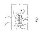
- a motor vehicle is equipped with a ventilation, heating and / or air conditioning installation 1 for modifying the aerothermal parameters of the air contained inside the passenger compartment of a motor vehicle.
- the installation 1 consists mainly of a plastic housing 2 which is arranged under a dashboard of the vehicle.
- the housing 2 is provided with at least one air intake opening 3 through which an air flow 4 enters the interior of the housing 2.
- the housing 2 is also provided with at least one delivery port air 5 through which the air flow 4 is discharged from the housing 2 to the passenger compartment of the vehicle.
- the latter houses a blower 6, such as a radial blower.
- the blower 6 comprises a volute 7 inside which at least one turbine 8 is rotated by an electric motor 9.
- the turbine 8 is for example a squirrel cage turbine, regardless of open bowl or closed bowl .
- the volute 7 consists of an enclosure which is made of plastic and which is provided with an air inlet 10 and an air outlet 11. Inside the volute 7, the flow of 4 air flows from the air inlet 10 to the air outlet 11 from the start of movement of the turbine 8 by the motor 9. The enclosure is sealed so that the air flow 4 s' flows from the air inlet 10 to the air outlet 11 without loss.
- the motor 9 and the turbine 8 are connected to each other via an axis of rotation 12 that the motor 9 comprises.
- a motor support 13 receives the motor 9, in particular by interlocking or by any other means. similar assembly technique.
- the motor support 13 is made of plastic.
- the turbine 8, the motor 9 and the motor support 13 together form a motor-fan unit 14 which is attached to the volute 7 via the motor support 13.
- the volute 7 is provided with a ring 41 for receiving the motor support 13.
- the ring 41 is for example a ring attached to the volute 7, in particular by interlocking or overmolding.
- the ring 41 and the volute 7 can be made from different respective materials.
- the ring 41 is for example still constituting the volute 7 forming with the latter a one-piece assembly made of a single material.
- the motor support 13 and the ring 41 constitute an assembly 13, 41 which allows a mechanical connection between the volute 7 and the motor-fan unit 14.
- the assembly 13, 41 forms a unit which allows the attachment of the motor support 13 and the ring 41 with each other, and thus the assembly of the volute 7 and the motor-fan unit 14 to form the blower 6.
- the volute 7 defines an internal volume 15 which houses the motor-fan unit 14 when the blower 6 is assembled.
- the internal volume 15 is more particularly delimited by an intake wall 16 through which the air inlet 10 is formed and a discharge wall 17 through which the air outlet 11 is formed.
- intake 16 is disposed vis-à-vis a receiving wall 18 on which is reported the engine support 13.
- the axis of rotation 12 of the turbine 8 extends substantially perpendicular to the inlet wall 16 and the receiving wall 18.
- the provisions of the present invention make it possible to relate the motor-fan unit 14 to the ring 41 either indiscriminately or from the inside of the volute 7 ( fig.2 ), or from outside the volute 7 ( fig.3 ).
- the provisions of the present invention also make it possible to separate the motor-fan unit 14 from the ring 41, either from the inside of the volute 7 ( fig.4 ), or from outside the volute 7 ( fig.5 ).
- the provisions of the present invention nevertheless make it possible to give the volute 7 a perfect seal, in the sense that the air flow 4 flows inside the volute 7 only from the air inlet 10. towards the air outlet 11.
- the motor-fan unit 14 is capable of being admitted inside the internal volume 15 via the air inlet 10, until the motor support 13 comes to close a window 19 arranged through the receiving wall 18.
- the approach of the motor-fan unit 14 is symbolized by the dotted arrow.
- the motor-fan unit 14 is capable of being admitted inside the internal volume 15 via the window 19, until the motor support 13 comes to close the window 19.
- motor-fan group 14 is again symbolized by the dotted arrow.
- the provisions of the present invention make it possible to remove the motor-fan unit 14 from the volute 7 either indiscriminately or internally. the volute 7, or from outside the volute 7.
- the motor-fan unit 14 can be removed via the air inlet 10. The movement of the motor-fan unit 14 is further symbolized by the dotted arrow.
- the motor-fan unit 14 can be removed via the window 19, the displacement of the motor-fan unit 14 is always symbolized by the dotted arrow.
- the motor support 13 has a diameter D which is smaller to a diameter D ' of the ring 41 and to a diameter D " of the window 19. More particularly, the diameter D' of the ring 41 is equivalent to the diameter D" of the window 19, and the ring 41 is arranged around the window 19 and participates in the delimitation of the latter.
- the motor support 13 is provided with at least one flexible sealing lip 20 which is able to deform during a passage of the motor support 13 through the window 19, and through the ring 41, as illustrated on the fig.6 and fig.7 .
- the flexible sealing lip 20 is able to retract so as not to constitute an obstacle during the passage of the motor support 13 through the ring 41, while ensuring a perfect seal once the engine mount 13 attached to the volute 7.
- the retraction of the flexible sealing lip 20 is obtained from a rocker of the latter around an anchoring point 21 of the flexible sealing lip 20 on the engine support 13.
- the flexible sealing lip 20 bears against an outer rim 22 of the window 19.
- This position of the flexible sealing lip 20 is for example due at an approach of the motor-fan unit 14 from the outside of the volute 7 (as shown in FIG. fig.3 ) until an inner face 23 of the flexible sealing lip 20 bears against the outer flange 22.
- This position of the flexible sealing lip 20 is also for example due to a retraction of the flexible lip 20 when approaching the motor-fan unit 14 from the inside of the volute 7 (as shown in FIG. fig.7 ).
- the flexible sealing lips 20 are two in number and are formed on an outer face 24 of a ring 25 that includes the motor support 13.
- the ring 25 has an axis of symmetry A which is parallel to the axis 12 of rotation of the turbine 8, in the assembly position of the motor-fan unit 14 on the volute 7.
- the flexible sealing lips 20 are when they formed inside respective plans of extension P1 , P2 which are perpendicular to the axis of symmetry A , in the assembly position of the motor-fan unit 14 on the volute 7.
- the flexible sealing lips 20 are more particularly formed on the edge of the outer face 24 and are reported by overmolding on the ring 25.
- the flexible sealing lips 20 are in particular made of an elastomer type material, such as styrene. ethylene-butylene-styrene, known as "SEBS".
- the flexible sealing lips 20 provide a sealing function of the volute 7 but do not participate in any positioning of the motor-fan unit 14 vis-à-vis the volute 7, which avoids any constraints related to a double positioning and finally reinforces the durability of the blower 6.
- the blower 6 comprises a fixing device 26,27 of the motor-blower unit 14 on the volute 7.
- Said device 26,27 comprises at least a first interlocking member 26 formed on the outer face 24 of the ring 25 and the less a second interlocking member 27 formed on an inner face 28 of the ring 41.
- the latter is preferably shaped as a circular ring 41 which has an axis of symmetry A ' .
- the first interlocking member 26 comprises a groove 30 formed in a radial plane P of the ring 25, the radial plane P being parallel to the respective extension planes P1 , P2 of the flexible sealing lips 20.
- the groove 30 comprises two orifices 31 which are formed in the radial plane P.
- the orifices 31 are opposed to each other with respect to a point of symmetry 42 of the groove 30.
- the orifices 31 are intended to allow the passage of a finger 32 constituting the second interlocking member 27, visible on the fig.13 .
- the finger 32 consists of a bulge formed on a plate 43 constituting the second interlocking member 27.
- the finger 32 is conformation complementary to a housing 33 that includes the groove 30 at its point of symmetry 32.
- the housing 33 is intended to receive said finger 32, in the assembly position of the blower 6. This establishment of the finger 32 inside the housing 33 is for example made from a quarter-turn movement performed by the ring 25 inside the ring 41, this quarter-turn movement being performed along the radial plane P.
- the fact that the groove 30 comprises two opposite orifices 31 allows the insertion of the finger 32 inside the groove 30 to the housing 33 either from a movement in the clockwise direction 34 or from a movement in the trigonometric direction 35.
- the groove 30 is delimited by two edges 36 which are symmetrical to one another with respect to the radial plane P.
- the borders 36 are for example arranged in an arc whose convex faces 37 vis-à-vis delimit the groove 30, so that the first interlocking member 26 is generally shaped as "X".
- the borders 36 comprise ends 39 which constitute first stops intended to come into contact with second stops 40 formed on either side of the second interlocking member 27.
- the second stops 40 are two in number and are disposed of. on either side of a general extension plane P ' of the second interlocking member 27. The latter is in particular arranged in "I" formed inside the general extension plane P' .
- each second stop 40 is provided at the same distance D1 of the general extension plane P '.
- This distance D1 is equivalent to a distance D1 ' corresponding to a gap between the groove 30 and the ends 39 of a border 36.
- the second stops 40 are arranged in sliding ramps arranged parallel to the general extension plane P' of such so that the ends 39 of a border 36 slide along a second stop 40 until the finger 32 slides inside the groove 30 to be finally placed inside the housing 33.
- the distribution on either side of the general extension plane P ' of the second stops 40 makes it possible to associate with the first nesting member 26 the first stop 40 which is best placed according to the approach of the motor support being made of a side of the general extension plane P ' or on the other side of the general extension plane P' , in other words from the inside of the 7 or the outside of the volute 7.
- the first stop 40 best placed is that which allows an alignment of the groove 30 and the finger 32 in the same plane.
- the two second stops 40 are easily accessible regardless of the direction of approach of the motor-fan unit 14 to the volute 7, the two second stops 40 are arranged on either side of the finger 32 relative to a transverse plane. P " orthogonal to the general extension plane P ' and comprising the finger 32. More particularly, the two second stops 40 are each spaced apart from the second interlocking member 26 by a distance E taken in the general extension plane P' These arrangements allow the fitting of the finger 32 inside the housing 33 either from the movement in the clockwise direction 34 or from the movement in the trigonometric direction 35, from a suitable choice of second stop. 40.
- a step of approaching the motor support 13 in which the axes of symmetry A , A ' of the ring 25 and the ring 41 are superimposed on one another.
Landscapes
- Engineering & Computer Science (AREA)
- Mechanical Engineering (AREA)
- General Engineering & Computer Science (AREA)
- Structures Of Non-Positive Displacement Pumps (AREA)
- Air-Conditioning For Vehicles (AREA)
Abstract
Description
- L'invention est du domaine des installations de ventilation, de chauffage et/ou de climatisation équipant un véhicule automobile. Elle a pour objet un ensemble formé d'un support-moteur et d'une bague de réception du support-moteur. Elle a aussi pour objet un groupe moto-ventilateur constitué du support-moteur, du moteur et d'une turbine mise en rotation par le moteur. Elle a encore pour objet une volute pourvue d'une telle bague. Elle a aussi pour objet un pulseur comprenant un tel groupe moto-ventilateur et une telle volute. Elle a enfin pour objet un procédé d'assemblage et de désassemblage d'un tel ensemble.
- Un véhicule automobile est couramment équipé d'une installation de ventilation, de chauffage et/ou de climatisation pour modifier les paramètres aérothermiques de l'air contenu à l'intérieur de l'habitacle du véhicule. Cette modification est obtenue à partir de la délivrance d'un flux d'air à l'intérieur de l'habitacle. L'installation est principalement constituée d'un boîtier qui est réalisé en matière plastique et qui est logé sous une planche de bord du véhicule. L'installation est pourvue d'au moins une bouche d'admission du flux d'air à l'intérieur du boîtier et d'au moins une bouche de délivrance du flux d'air hors du boîtier vers l'habitacle. L'installation loge un pulseur pour générer le flux d'air et le faire circuler depuis la bouche d'admission vers la bouche de délivrance.
- Le pulseur comprend une volute sur laquelle est rapporté un groupe moto-ventilateur. Ce dernier est principalement constitué d'une turbine, d'un moteur apte à mettre en mouvement la turbine à l'intérieur de la volute et d'un support-moteur. Le support-moteur est constitué d'une pièce réalisée en matière plastique sur laquelle est fixé le moteur porteur de la turbine. La mise en mouvement de la turbine permet la génération du flux d'air.
- La volute est constituée d'une enceinte pourvue d'une entrée d'air à travers laquelle le flux d'air est admis à l'intérieur de l'enceinte et d'une sortie d'air à travers laquelle le flux d'air est évacué hors de l'enceinte. L'enceinte comporte une paroi d'admission d'air à travers laquelle est ménagée l'entrée d'air, une paroi d'évacuation d'air à travers laquelle est ménagée la sortie d'air et une paroi de réception du groupe moto-ventilateur. La paroi de réception est pourvue d'une fenêtre qui est obturée par le groupe moto-ventilateur lorsque ce dernier est rapporté sur la volute. De manière courante, la paroi d'admission et la paroi de réception sont opposées l'une à l'autre et sont reliées l'une à l'autre par l'intermédiaire de la paroi d'évacuation. Cette dernière prend par exemple la forme d'un escargot ou d'une spirale.
- Pour permettre un assemblage du groupe moto-ventilateur et de la volute entre eux, le support-moteur et la volute sont pourvus d'organes coopérants de fixation par emboîtement.
- Les concepteurs de tels pulseurs font habituellement le choix préalable de permettre un montage du groupe moto-ventilateur soit par l'intérieur de la volute, soit par l'extérieur de cette dernière.
- Dans le premier cas, le groupe moto-ventilateur est inséré à l'intérieur de la volute par l'intermédiaire de l'entrée d'air jusqu'à ce que le support-moteur vienne en butée contre la volute, puis les organes coopérants sont emboîtés l'un avec l'autre, notamment suite à un quart-de-tour effectué par le groupe moto-ventilateur à l'intérieur de la volute.
- Dans le deuxième cas, le groupe moto-ventilateur est inséré à l'intérieur de la volute par l'intermédiaire de la fenêtre jusqu'à ce que le support-moteur vienne en butée contre la volute, puis les organes coopérants sont emboîtés l'un avec l'autre.
- Dans les deux cas précités, une opération de démontage du groupe moto-ventilateur et de la volute comprend les mêmes étapes que l'opération de montage mais réalisées en sens inverse. Autrement dit, le montage et le démontage comprennent des déplacements du groupe moto-ventilateur qui sont effectués selon une même direction mais en des sens opposés. Ces déplacements constituent finalement un aller-retour du groupe moto-ventilateur.
- De telles modalités s'avèrent contraignantes par manque de flexibilité et par obligation d'avoir à monter et à démonter le pulseur exclusivement selon l'un ou l'autre des choix proposés. En effet, lors d'une opération de maintenance nécessitant le démontage du groupe moto-ventilateur sur la volute, il est nécessaire de trouver libre un espace à travers lequel le groupe moto-ventilateur a été approché lors de son installation sur la volute. Or cet espace est fréquemment encombré après le montage du groupe moto-ventilateur, notamment par la colonne de direction du véhicule. Il en résulte de multiples manipulations pour démonter le groupe moto-ventilateur ce qui est consommateur de temps et préjudiciable. Par ailleurs, il est souhaité par les concepteurs de tels pulseurs que ces derniers soient adaptés à des véhicules présentant indifféremment une conduite à droite ou une conduite à gauche, c'est-à-dire dont la colonne de direction est susceptible d'être disposée soit en vis-à-vis de la fenêtre, soit en vis-à-vis de l'entrée d'air. Il en découle finalement une impossibilité d'utiliser un tel pulseur dans le cadre des contraintes susvisées.
- Un premier but de la présente invention est de proposer un ensemble formé d'un support-moteur destiné à recevoir un moteur, et d'une bague de réception du support-moteur, cet ensemble étant constitutif d'un pulseur d'une installation de ventilation, de chauffage et/ou de climatisation, l'ensemble étant agencé pour permettre un choix diversifié d'option de montage et de démontage d'un groupe moto-ventilateur, qui comprend le support moteur, sur une volute pourvue d'une telle bague. Un autre but de la présente invention est de proposer un groupe moto-ventilateur comprenant un tel support-moteur. Un autre but est de proposer une volute équipée d'une telle bague. Un autre but est de proposer un pulseur comprenant ladite volute apte à recevoir un tel groupe moto-ventilateur. Un dernier but est de proposer un procédé de montage et/ou de démontage d'un tel groupe moto-ventilateur sur la volute.
- L'ensemble de la présente invention est un ensemble constitutif d'un pulseur d'une installation de ventilation, de chauffage et/ou de climatisation. L'ensemble est formé d'un support-moteur destiné à recevoir un moteur et d'une bague destiné à recevoir le support-moteur. Le support-moteur est pourvu d'au moins une lèvre souple d'étanchéité apte à se déformer lors d'un passage du support-moteur à travers la bague.
- Le support-moteur est avantageusement d'un diamètre D qui est inférieur à un diamètre D' de la bague.
- La lèvre souple d'étanchéité est préférentiellement ménagée sur une face externe d'une couronne que comporte le support-moteur.
- La lèvre souple d'étanchéité est notamment ménagée en bordure de la face externe.
- La lèvre souple d'étanchéité est préférentiellement rapportée par surmoulage sur la couronne.
- La lèvre souple d'étanchéité est par exemple réalisée en un matériau de type élastomère.
- La face externe est avantageusement pourvue d'un premier organe d'emboîtement destiné à coopérer avec un deuxième organe d'emboitement ménagé sur une face interne de la bague.
- Le premier organe d'emboîtement comporte préférentiellement une gorge ménagée selon un plan radial P de la couronne.
- La gorge comprend avantageusement au moins un orifice destiné à permettre le passage d'un doigt constitutif du deuxième organe d'emboîtement.
- La gorge comprend préférentiellement deux orifices qui sont opposés l'un à l'autre par rapport à un point de symétrie de la gorge et qui sont ménagés à l'intérieur du plan radial P.
- La gorge comporte avantageusement un logement de réception dudit doigt.
- La gorge est notamment délimitée par deux bordures qui sont symétriques l'une de l'autre par rapport au plan radial P.
- De préférence, au moins une bordure est pourvue d'au moins une première butée destinée à venir en contact contre au moins une deuxième butée ménagée sur la face interne de la bague.
- Un groupe moto-ventilateur de la présente invention comprend un moteur, une turbine et un tel support-moteur.
- Une volute de la présente invention est pourvue d'une telle bague.
- Un pulseur de la présente invention est un pulseur d'une installation de ventilation, de chauffage et/ou de climatisation qui comprend une telle volute et un tel groupe moto-ventilateur.
- Un procédé d'assemblage et de désassemblage d'un tel ensemble est principalement caractérisé en ce que le procédé comporte une phase de montage et une phase de démontage qui sont effectuées dans une même direction et dans un même sens.
- La présente invention sera mieux comprise à la lecture de la description qui va en être faite d'exemples de réalisation, en relation avec les figures des planches annexées, dans lesquelles :
- La
fig.1 est une vue schématique en coupe d'une installation de ventilation, de chauffage et/ou de climatisation logeant un pulseur selon la présente invention. - Les
fig.2 et fig.3 sont des vues schématiques d'étape d'un procédé de montage d'un groupe moto-ventilateur et d'une volute constitutifs du pulseur illustré sur la figure précédente. - Les
fig.4 et fig.5 sont des vues schématiques d'étape d'un procédé de démontage d'un groupe moto-ventilateur et d'une volute constitutifs du pulseur illustré sur lafig.1 . - Les
fig.6 à fig.9 sont des vues schématiques partielles et en coupe d'un support-moteur et de la volute constitutifs du pulseur illustré sur lafig.1 . - La
fig.10 est une vue schématique en perspective du support-moteur représenté sur lesfig.6 à fig.9 . - La
fig.11 est une vue en perspective d'un ensemble selon la présente invention qui est formé du support-moteur illustré sur lafig.10 et d'une bague de réception du support-moteur. - La
fig.12 est une vue schématique d'un premier organe d'emboitement équipant le support-moteur représenté sur lafig.10 . - La
fig.13 est une vue schématique d'un deuxième organe d'emboitement équipant la bague représentée sur lafig.11 . - Les
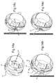
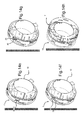
fig.14a à fig.14h sont des illustrations schématiques d'étape de montage/démontage du support-moteur sur la bague. - Sur la
fig.1 , un véhicule automobile est équipé d'une installation 1 de ventilation, de chauffage et/ou de climatisation pour modifier les paramètres aérothermiques de l'air contenu à l'intérieur de l'habitacle d'un véhicule automobile. L'installation 1 est principalement constituée d'un boîtier 2 en matière plastique qui est disposé sous une planche de bord du véhicule. Le boîtier 2 est muni d'au moins une bouche d'admission d'air 3 à travers laquelle un flux d'air 4 pénètre à l'intérieur du boîtier 2. Le boîtier 2 est également pourvu d'au moins une bouche de délivrance d'air 5 à travers laquelle le flux d'air 4 est évacué hors du boîtier 2 vers l'habitacle du véhicule. - Pour générer et faire circuler le flux d'air 4 à l'intérieur du boîtier 2, ce dernier loge un pulseur 6, tel qu'un pulseur radial. Le pulseur 6 comprend une volute 7 à l'intérieur de laquelle au moins une turbine 8 est mise en rotation par un moteur électrique 9. La turbine 8 est par exemple une turbine à cage d'écureuil, indifféremment à bol ouvert ou à bol fermé. La volute 7 est constituée d'une enceinte qui est réalisée en matière plastique et qui est pourvue d'une entrée d'air 10 et d'une sortie d'air 11. A l'intérieur de la volute 7, le flux d'air 4 circule depuis l'entrée d'air 10 vers la sortie d'air 11 à partir de la mise en mouvement de la turbine 8 par le moteur 9. L'enceinte est étanche de sorte que le flux d'air 4 s'écoule depuis l'entrée d'air 10 jusqu'à la sortie d'air 11 sans déperdition.
- Le moteur 9 et la turbine 8 sont reliés l'un à l'autre par l'intermédiaire d'un axe de rotation 12 que comporte le moteur 9. Un support-moteur 13 reçoit le moteur 9, notamment par emboîtement ou par toute autre technique d'assemblage analogue. Le support-moteur 13 est réalisé en matière plastique. La turbine 8, le moteur 9 et le support-moteur 13 forment conjointement un groupe moto-ventilateur 14 qui est rapporté sur la volute 7 par l'intermédiaire du support-moteur 13.
- Plus particulièrement, la volute 7 est pourvue d'une bague 41 de réception du support-moteur 13. La bague 41 est par exemple une bague rapportée sur la volute 7, notamment par emboîtement, voire par surmoulage. Dans ce cas-là, la bague 41 et la volute 7 sont susceptibles d'être réalisées à partir de matériaux respectifs distincts. La bague 41 est par exemple encore constitutive de la volute 7 en formant avec cette dernière un ensemble monobloc réalisé en un matériau unique.
- Le support-moteur 13 et la bague 41 constituent un ensemble 13,41 qui permet une liaison mécanique entre la volute 7 et le groupe moto-ventilateur 14. L'ensemble 13,41 forme un tout qui permet la fixation du support-moteur 13 et de la bague 41 l'un avec l'autre, et donc l'assemblage de la volute 7 et du groupe moto-ventilateur 14 pour former le pulseur 6.
- La volute 7 délimite un volume interne 15 qui loge le groupe moto-ventilateur 14 lorsque le pulseur 6 est assemblé. Le volume interne 15 est plus particulièrement délimité par une paroi d'admission 16 à travers laquelle est ménagée l'entrée d'air 10 et une paroi d'évacuation 17 à travers laquelle est ménagée la sortie d'air 11. La paroi d'admission 16 est disposée en vis-à-vis d'une paroi de réception 18 sur laquelle est rapportée le support-moteur 13. En position d'assemblage du pulseur 6, l'axe de rotation 12 de la turbine 8 s'étend sensiblement perpendiculairement à la paroi d'admission 16 et la paroi de réception 18.
- Lors de l'assemblage du pulseur 6, les éléments constitutifs du groupe moto-ventilateur 14 sont assemblés entre eux, puis sont rapportés ensemble sur la bague 41. En cas de dysfonctionnement de la turbine 8 et/ou du moteur 9, il est souhaitable de pouvoir désolidariser aisément et rapidement le groupe moto-ventilateur défectueux 14 de la bague 41 et de le remplacer par un groupe moto-ventilateur de rechange 14.
- Les dispositions de la présente invention permettent de rapporter le groupe moto-ventilateur 14 sur la bague 41 indifféremment soit par l'intérieur de la volute 7 (
fig.2 ), soit par l'extérieur de la volute 7 (fig.3 ). Les dispositions de la présente invention permettent aussi de désolidariser le groupe moto-ventilateur 14 de la bague 41, soit par l'intérieur de la volute 7 (fig.4 ), soit par l'extérieur de la volute 7 (fig.5 ). Enfin les dispositions de la présente invention permettent néanmoins de conférer à la volute 7 une étanchéité parfaite, dans le sens où le flux d'air 4 ne s'écoule à l'intérieur de la volute 7 que depuis l'entrée d'air 10 vers la sortie d'air 11. - Ainsi, tel qu'illustré sur la
figure 2 , le groupe moto-ventilateur 14 est susceptible d'être admis à l'intérieur du volume interne 15 par l'intermédiaire de l'entrée d'air 10, jusqu'à ce que le support-moteur 13 vienne obturer une fenêtre 19 ménagée à travers la paroi de réception 18. L'approche du groupe moto-ventilateur 14 est symbolisée par la flèche pointillée. - Ainsi encore, et tel qu'illustré sur la
figure 3 , le groupe moto-ventilateur 14 est susceptible d'être admis à l'intérieur du volume interne 15 par l'intermédiaire de la fenêtre 19, jusqu'à ce que le support-moteur 13 vienne obturer la fenêtre 19. L'approche du groupe moto-ventilateur 14 est à nouveau symbolisée par la flèche pointillée. - Lors d'une éventuelle opération de maintenance nécessitant la désolidarisation du groupe moto-ventilateur 14 et de la bague 41, les dispositions de la présente invention permettent d'ôter le groupe moto-ventilateur 14 de la volute 7 indifféremment soit par l'intérieur de la volute 7, soit par l'extérieur de la volute 7. Ainsi, tel qu'illustré sur la
figure 4 , le groupe moto-ventilateur 14 est susceptible d'être retiré par l'intermédiaire de l'entrée d'air 10. Le mouvement du groupe moto-ventilateur 14 est encore symbolisé par la flèche pointillée. - Selon une autre possibilité offerte par la présente invention, et tel qu'illustré sur la
figure 5 , le groupe moto-ventilateur 14 est susceptible d'être retiré par l'intermédiaire de la fenêtre 19, le déplacement du groupe moto-ventilateur 14 étant toujours symbolisé par la flèche pointillée. - A cet effet, et dans le cas fréquent où le support moteur 13 est globalement circulaire, où la bague 41 est conformée en un anneau circulaire, et où la fenêtre 19 est également circulaire, le support-moteur 13 présente un diamètre D qui est inférieur à un diamètre D' de la bague 41 ainsi qu'à un diamètre D" de la fenêtre 19. Plus particulièrement, le diamètre D' de la bague 41 est équivalent au diamètre D" de la fenêtre 19, et la bague 41 est ménagée au pourtour de la fenêtre 19 et participe de la délimitation de cette dernière.
- Ces résultats avantageux sont atteints par le fait que le support-moteur 13 est pourvu d'au moins une lèvre souple d'étanchéité 20 qui est apte à se déformer lors d'un passage du support-moteur 13 à travers la fenêtre 19, et à travers la bague 41, tel qu'illustré sur les
fig.6 et fig.7 . Plus précisément, la lèvre souple d'étanchéité 20 est à même de s'escamoter pour ne pas constituer un obstacle lors du passage du support-moteur 13 à travers la bague 41, tout en assurant une étanchéité parfaite une fois le support-moteur 13 rapporté sur la volute 7. L'escamotage de la lèvre souple d'étanchéité 20 est obtenu à partir d'une bascule de cette dernière autour d'un point d'ancrage 21 de la lèvre souple d'étanchéité 20 sur le support-moteur 13. - Sur la
fig.8 , en position de fixation du groupe moto-ventilateur 14 sur la volute 7, la lèvre souple d'étanchéité 20 vient en appui contre un rebord externe 22 de la fenêtre 19. Cette position de la lèvre souple d'étanchéité 20 est par exemple due à une approche du groupe moto-ventilateur 14 par l'extérieur de la volute 7 (tel qu'illustré sur lafig.3 ) jusqu'à ce qu'une face intérieure 23 de la lèvre souple d'étanchéité 20 vienne en appui contre le rebord externe 22. Cette position de la lèvre souple d'étanchéité 20 est aussi par exemple due à un escamotage de la lèvre souple d'étanchéité 20 lors d'une approche du groupe moto-ventilateur 14 par l'intérieur de la volute 7 (tel qu'illustré sur lafig.7 ). - A partir de la position de fixation du groupe moto-ventilateur 14 sur la volute 7 illustré sur la
fig.8 , il est possible de démonter le groupe moto-ventilateur 14 par exemple par l'intérieur de la volute 7, tel qu'illustré sur lafig.6 . - A partir de la position de fixation du groupe moto-ventilateur 14 sur la volute 7 illustré sur la
fig.8 , il est aussi possible de démonter le groupe moto-ventilateur 14 par exemple par l'extérieur de la volute 7, tel qu'illustré sur lafig.9 , le déplacement du groupe moto-ventilateur 14 étant symbolisé par la flèche pointillée. - Sur la
fig.10 , les lèvres souples d'étanchéité 20 sont au nombre de deux et sont ménagées sur une face externe 24 d'une couronne 25 que comporte le support-moteur 13. La couronne 25 comporte un axe de symétrie A qui est parallèle à l'axe de rotation 12 de la turbine 8, en position d'assemblage du groupe moto-ventilateur 14 sur la volute 7. Les lèvres souples d'étanchéité 20 sont quand à elles ménagées à l'intérieur de plans respectifs d'extension P1, P2 qui sont perpendiculaires à l'axe de symétrie A, en position d'assemblage du groupe moto-ventilateur 14 sur la volute 7. - Les lèvres souples d'étanchéité 20 sont plus particulièrement ménagées en bordure de la face externe 24 et sont rapportées par surmoulage sur la couronne 25. Les lèvres souples d'étanchéité 20 sont notamment réalisées en un matériau de type élastomère, tel que du styrène-éthylène-butylène-styrène, connu sous l'appellation « SEBS ».
- Il découle de l'ensemble de ces dispositions que les lèvres souples d'étanchéité 20 assurent une fonction d'étanchéité de la volute 7 mais ne participent en rien d'un quelconque positionnement du groupe moto-ventilateur 14 vis-à-vis de la volute 7, ce qui évite toutes contraintes liées à un double positionnement et finalement conforte la pérennité du pulseur 6.
- Sur la
fig.11 , le pulseur 6 comporte un dispositif de fixation 26,27 du groupe moto-ventilateur 14 sur la volute 7. Ledit dispositif 26,27 comprend au moins un premier organe d'emboîtement 26 ménagé sur la face externe 24 de la couronne 25 et au moins un deuxième organe d'emboîtement 27 ménagé sur une face interne 28 de la bague 41. Cette dernière est préférentiellement conformée en une bague circulaire 41 qui comporte un axe de symétrie A'. Lors de l'assemblage du groupe moto-ventilateur 14 sur la volute 7, les axes de symétrie A, A' de la couronne 25 et de la bague 41 sont superposés l'un à l'autre, de telle sorte que la face interne 28 et la face externe 24 sont placées en contact étroit l'une contre l'autre, le premier organe d'emboîtement 26 étant disposé en vis-à-vis du deuxième organe d'emboîtement 27. - Sur la
fig.12 , le premier organe d'emboîtement 26 comporte une gorge 30 ménagée selon un plan radial P de la couronne 25, le plan radial P étant parallèle aux plans respectifs d'extension P1, P2 des lèvres souples d'étanchéité 20. La gorge 30 comprend deux orifices 31 qui sont ménagés dans le plan radial P. Les orifices 31 sont opposés l'un à l'autre par rapport à un point de symétrie 42 de la gorge 30. Les orifices 31 sont destinés à permettre le passage d'un doigt 32 constitutif du deuxième organe d'emboîtement 27, visible sur lafig.13 . Le doigt 32 est constitué d'un renflement ménagé sur une platine 43 constitutive du deuxième organe d'emboîtement 27. Le doigt 32 est de conformation complémentaire à un logement 33 que comporte la gorge 30 en son point de symétrie 32. Le logement 33 est destiné à recevoir ledit doigt 32, en position d'assemblage du pulseur 6. Cette mise en place du doigt 32 à l'intérieur du logement 33 est par exemple effectué à partir d'un mouvement de type quart-de-tour effectué par la couronne 25 à l'intérieur de la bague 41, ce mouvement de quart-de-tour étant effectué selon le plan radial P. - Le fait que la gorge 30 comprenne deux orifices opposés 31 permet l'insertion du doigt 32 à l'intérieur de la gorge 30 jusqu'au logement 33 soit à partir d'un mouvement dans le sens horaire 34, soit à partir d'un mouvement dans le sens trigonométrique 35. La gorge 30 est délimitée par deux bordures 36 qui sont symétriques l'une de l'autre par rapport au plan radial P. Les bordures 36 sont par exemple agencées en arc de cercle dont des faces convexes 37 en vis-à-vis délimitent la gorge 30, de telle sorte que le premier organe d'emboitement 26 est globalement conformé en « X ». Les bordures 36 comportent des extrémités 39 qui constituent des premières butées destinées à venir en contact contre des deuxièmes butées 40 ménagées de part et d'autre du deuxième organe d'emboîtement 27. Les deuxièmes butées 40 sont au nombre de deux et sont disposées de part et d'autre d'un plan d'extension général P' du deuxième organe d'emboîtement 27. Ce dernier est notamment agencé en « I » ménagé à l'intérieur du plan d'extension général P'.
- Plus particulièrement, chaque deuxième butée 40 est ménagée à une même distance D1 du plan d'extension général P'. Cette distance D1 est équivalente à une distance D1' correspondant à un écart entre la gorge 30 et les extrémités 39 d'une bordure 36. Les deuxièmes butées 40 sont agencées en rampes de glissement ménagées parallèlement au plan d'extension général P' de telle sorte que les extrémités 39 d'une bordure 36 glissent le long d'une deuxième butée 40 jusqu'à ce que le doigt 32 coulisse à l'intérieur de la gorge 30 pour être finalement placé à l'intérieur du logement 33. La répartition de part et d'autre du plan d'extension général P' des deuxièmes butées 40 permet d'associer au premier organe d'emboitement 26 la première butée 40 la mieux placée selon que l'approche du support-moteur se fait d'un côté du plan d'extension général P' ou de l'autre côté du plan d'extension général P', autrement dit de l'intérieur de la volute 7 ou de l'extérieur de la volute 7. La première butée 40 la mieux placée est celle qui permet un alignement de la gorge 30 et du doigt 32 dans un même plan.
- Pour que les deux deuxièmes butées 40 soient aisément accessibles quelque soit le sens d'approche du groupe moto-ventilateur 14 vers la volute 7, les deux deuxièmes butées 40 sont disposées de part et d'autre du doigt 32 par rapport à un plan transverse P" orthogonal au plan d'extension général P' et comportant le doigt 32. Plus particulièrement, les deux deuxièmes butées 40 sont chacune espacées du deuxième organe d'emboîtement 26 d'un écart E pris dans le plan d'extension général P'. Ces dispositions permettent la mise en place du doigt 32 à l'intérieur du logement 33 soit à partir du mouvement dans le sens horaire 34, soit à partir du mouvement dans le sens trigonométrique 35, à partir d'un choix approprié de deuxième butée 40.
- Sur la
fig.14a , est représentée une étape d'approche du support-moteur 13 dans laquelle les axes de symétrie A, A' de la couronne 25 et de la bague 41 sont superposés l'un à l'autre. - Sur la
fig.14b , est représentée une étape d'entrée du support-moteur 13 dans laquelle la face interne 28 et la face externe 24 sont placées en vis-à-vis l'une de l'autre. Lors de cette étape, la lèvre souple d'étanchéité 20 est apte à se déformer au contact des deuxièmes butées 40 et du deuxième organe d'emboitement 27. - Sur la
fig.14c , est représentée une étape de mise en contact des premières extrémités 39 du premier organe d'emboitement 26 contre une deuxième butée 40. - Sur la
fig.14d , est représentée une étape d'engagement du deuxième organe d'emboitement 27 à l'intérieur de la gorge 30. - Sur la
fig.14e , est représentée une étape de verrouillage du support-moteur 13 sur la bague 41 à partir d'un placement du doigt 32 à l'intérieur du logement 33. - Sur la
fig.14f , est représentée une étape de déverrouillage du support-moteur 13 et de la bague 41 à partir d'un placement du doigt 32 hors du logement 33. - Sur la
fig.14g , est représentée une étape de glissement des premières butées 39 le long de la deuxième butée 40. - Sur la
fig.14h , est représentée une étape de désengagement du support-moteur 13 hors de la bague 41.
Claims (17)
- Ensemble (13,41) constitutif d'un pulseur (6) d'une installation (1) de ventilation, de chauffage et/ou de climatisation, l'ensemble (13,41) étant formé d'un support-moteur (13) destiné à recevoir un moteur (9) et d'une bague (41) destiné à recevoir le support-moteur (13), caractérisé en ce que le support-moteur (13) est pourvu d'au moins une lèvre souple d'étanchéité (20) apte à se déformer lors d'un passage du support-moteur (13) à travers la bague (41).
- Ensemble (13,41) selon la revendication 1, caractérisé en ce que le support-moteur (13) est d'un diamètre D qui est inférieur à un diamètre D' de la bague (41).
- Ensemble (13,41) selon l'une quelconque des revendications précédentes, caractérisé en ce que la lèvre souple d'étanchéité (20) est ménagée sur une face externe (24) d'une couronne (25) que comporte le support-moteur (13).
- Ensemble (13,41) selon la revendication 3, caractérisé en ce que la lèvre souple d'étanchéité (20) est ménagée en bordure de la face externe (24).
- Ensemble (13,41) selon l'une quelconque des revendications 3 et 4, caractérisé en ce que la lèvre souple d'étanchéité (20) est rapportée par surmoulage sur la couronne (25).
- Ensemble (13,41) selon l'une quelconque des revendications précédentes, caractérisé en ce que la lèvre souple d'étanchéité (20) est réalisée en un matériau de type élastomère.
- Ensemble (13,41) selon l'une quelconque des revendications 3 à 6, caractérisé en ce que la face externe (24) est pourvue d'un premier organe d'emboîtement (26) destiné à coopérer avec un deuxième organe d'emboitement (27) ménagé sur une face interne (28) de la bague (41).
- Ensemble (13,41) selon la revendication 7, caractérisé en ce que le premier organe d'emboîtement (26) comporte une gorge (30) ménagée selon un plan radial P de la couronne (25).
- Ensemble (13,41) selon la revendication 8, caractérisé en ce que la gorge (30) comprend au moins un orifice (31) destiné à permettre le passage d'un doigt (32) constitutif du deuxième organe d'emboîtement (27).
- Ensemble (13,41) selon la revendication 9, caractérisé en ce que la gorge (30) comprend deux orifices (31) qui sont opposés l'un à l'autre par rapport à un point de symétrie (42) de la gorge (30) et qui sont ménagés à l'intérieur du plan radial P.
- Ensemble (13,41) selon l'une quelconque des revendications 8 à 10, caractérisé en ce que la gorge (30) comporte un logement (33) de réception dudit doigt (32).
- Ensemble (13,41) selon l'une quelconque des revendications 8 à 11, caractérisé en ce que la gorge (30) est délimitée par deux bordures (36) qui sont symétriques l'une de l'autre par rapport au plan radial P.
- Ensemble (13,41) selon la revendication 12, caractérisé en ce qu'au moins une bordure (36) est pourvue d'au moins une première butée (39) destinée à venir en contact contre au moins une deuxième butée (40) ménagée sur la face interne (28) de la bague (41).
- Groupe moto-ventilateur (14) comprenant un moteur (9), une turbine (8) et un support-moteur (13) caractérisé en ce que le support-moteur (13) est pourvu d'au moins une lèvre souple d'étanchéité (20) apte à se déformer lors d'un passage du support-moteur (13) à travers une bague (41).
- Volute pourvue d'une bague (41) de réception d'un support-moteur (13) équipant un groupe moto-ventilateur (14) selon la revendication 14.
- Pulseur (6) d'une installation (1) de ventilation, de chauffage et/ou de climatisation comprenant une volute (7) selon la revendication 15 et un groupe moto-ventilateur (14) selon la revendication 14.
- Procédé d'assemblage et de désassemblage d'un ensemble (13,41) selon l'une quelconque des revendications 1 à 13, caractérisé en ce que le procédé comporte une phase de montage et une phase de démontage qui sont effectuées dans une même direction et dans un même sens.
Applications Claiming Priority (1)
| Application Number | Priority Date | Filing Date | Title |
|---|---|---|---|
| FR0903254A FR2947591B1 (fr) | 2009-07-02 | 2009-07-02 | Ensemble forme d'un support-moteur et d'une bague de reception de ce dernier |
Publications (2)
| Publication Number | Publication Date |
|---|---|
| EP2282063A1 true EP2282063A1 (fr) | 2011-02-09 |
| EP2282063B1 EP2282063B1 (fr) | 2020-09-02 |
Family
ID=41528780
Family Applications (1)
| Application Number | Title | Priority Date | Filing Date |
|---|---|---|---|
| EP10167380.4A Active EP2282063B1 (fr) | 2009-07-02 | 2010-06-25 | Ensemble formé d'un support-moteur et d'une bague de réception de ce dernier |
Country Status (4)
| Country | Link |
|---|---|
| EP (1) | EP2282063B1 (fr) |
| JP (1) | JP5829011B2 (fr) |
| CN (1) | CN102019837B (fr) |
| FR (1) | FR2947591B1 (fr) |
Families Citing this family (4)
| Publication number | Priority date | Publication date | Assignee | Title |
|---|---|---|---|---|
| DE102012109546A1 (de) * | 2012-10-08 | 2014-04-10 | Ebm-Papst Mulfingen Gmbh & Co. Kg | "Wandring für einen Axialventilator" |
| CN103723029A (zh) * | 2013-12-31 | 2014-04-16 | 天津清源电动车辆有限责任公司 | 一种在电动汽车中连接电动水泵与车身架的装置 |
| FR3078019A1 (fr) * | 2018-02-19 | 2019-08-23 | Valeo Systemes Thermiques | Dispositif de chauffage, ventilation et/ou climatisation et groupe moto-ventilateur pour vehicule automobile |
| DE102018119596A1 (de) * | 2018-08-13 | 2020-02-13 | Stiebel Eltron Gmbh & Co. Kg | Lagerungsvorrichtung eines Lüftungssystems und Lüftungssystem |
Citations (4)
| Publication number | Priority date | Publication date | Assignee | Title |
|---|---|---|---|---|
| DE8712505U1 (de) * | 1987-09-16 | 1987-12-03 | Ashauer, Ernst, Dipl.-Ing., 6940 Weinheim | Dachlukenanordnung für Wohnwagen, Wohnmobile od.dgl. |
| DE9016496U1 (de) * | 1990-12-05 | 1991-03-14 | Behr GmbH & Co, 7000 Stuttgart | Axiallüfter |
| EP1865207A2 (fr) * | 2006-06-05 | 2007-12-12 | Deere & Company | Carénage de ventilateur |
| EP2078864A1 (fr) * | 2008-01-11 | 2009-07-15 | MAICO ELEKTROAPPARATE-FABRIK GmbH | Ventilateur à tube |
Family Cites Families (6)
| Publication number | Priority date | Publication date | Assignee | Title |
|---|---|---|---|---|
| JPS58128916A (ja) * | 1982-01-28 | 1983-08-01 | Nissan Motor Co Ltd | ブロワモ−タの取付構造 |
| JPS58149674U (ja) * | 1982-04-01 | 1983-10-07 | 旭有機材工業株式会社 | かんがい用弁 |
| JP3489221B2 (ja) * | 1994-10-31 | 2004-01-19 | 株式会社デンソー | 車両用空気調和装置 |
| US6386845B1 (en) * | 1999-08-24 | 2002-05-14 | Paul Bedard | Air blower apparatus |
| JP2001309601A (ja) * | 2000-04-25 | 2001-11-02 | Asmo Co Ltd | モータホルダ |
| ITBO20040743A1 (it) * | 2004-11-30 | 2005-02-28 | Spal Srl | Impianto di ventilazione, in particolare per autoveicoli |
-
2009
- 2009-07-02 FR FR0903254A patent/FR2947591B1/fr not_active Expired - Fee Related
-
2010
- 2010-06-25 EP EP10167380.4A patent/EP2282063B1/fr active Active
- 2010-07-02 JP JP2010151655A patent/JP5829011B2/ja not_active Expired - Fee Related
- 2010-07-02 CN CN201010511653.8A patent/CN102019837B/zh active Active
Patent Citations (4)
| Publication number | Priority date | Publication date | Assignee | Title |
|---|---|---|---|---|
| DE8712505U1 (de) * | 1987-09-16 | 1987-12-03 | Ashauer, Ernst, Dipl.-Ing., 6940 Weinheim | Dachlukenanordnung für Wohnwagen, Wohnmobile od.dgl. |
| DE9016496U1 (de) * | 1990-12-05 | 1991-03-14 | Behr GmbH & Co, 7000 Stuttgart | Axiallüfter |
| EP1865207A2 (fr) * | 2006-06-05 | 2007-12-12 | Deere & Company | Carénage de ventilateur |
| EP2078864A1 (fr) * | 2008-01-11 | 2009-07-15 | MAICO ELEKTROAPPARATE-FABRIK GmbH | Ventilateur à tube |
Also Published As
| Publication number | Publication date |
|---|---|
| CN102019837B (zh) | 2015-07-22 |
| JP2011011739A (ja) | 2011-01-20 |
| FR2947591B1 (fr) | 2011-07-22 |
| CN102019837A (zh) | 2011-04-20 |
| FR2947591A1 (fr) | 2011-01-07 |
| EP2282063B1 (fr) | 2020-09-02 |
| JP5829011B2 (ja) | 2015-12-09 |
Similar Documents
| Publication | Publication Date | Title |
|---|---|---|
| EP2947328B1 (fr) | Micro-soufflante à étanchéité améliorée pour ventilateur médical et son procédé d'assemblage | |
| FR2983262A1 (fr) | Support-moteur a manchon de refroidissement amorti et groupe moto-ventilateur integrant un tel support-moteur | |
| FR2961749A1 (fr) | Dispositif de reception d'un moteur de pulseur d'une installation de ventilation d'un vehicule | |
| EP2282063B1 (fr) | Ensemble formé d'un support-moteur et d'une bague de réception de ce dernier | |
| FR3004700A1 (fr) | Nacelle pour turboreacteur d’aeronef a levre avant etendue | |
| CA2664034A1 (fr) | Structure d'entree d'air deposable pour nacelle de turboreacteur | |
| EP2456053A1 (fr) | Dispositif de support-moteur, en particulier pour un groupe moto-ventilateur | |
| WO2014006305A1 (fr) | Climatiseur, notamment pour véhicule automobile | |
| EP3736156B1 (fr) | Dispositif d'aération pour un véhicule, procédé de montage associé | |
| EP2586119B1 (fr) | Support moteur a dispositif de limitation de mouvements | |
| EP1595771A2 (fr) | Clapet d'obturation pour boíte à eau de véhicule automobile et boíte à eau correspondante | |
| WO2018002560A1 (fr) | Agencement pour la fixation d'une bielle de volet d'inversion de poussée sur une structure interne fixe d'une nacelle de turboréacteur et procédé de montage/démontage associé | |
| FR3063777A1 (fr) | Agencement de rouet a double etage pour un turbocompresseur centrifuge a double etage | |
| EP3159225A1 (fr) | Dispositif de connexion pour balai d'essuie-glace | |
| EP3991277B1 (fr) | Support de moteur pour dispositif de chauffage, de ventilation et/ou de climatisation pour véhicule automobile | |
| WO2013120704A1 (fr) | Dispositif de fixation d'un actionneur sur une paroi, notamment une paroi d'une installation de chauffage, ventilation et/ou climatisation | |
| EP4051909B1 (fr) | Support de moteur et dispositif de chauffage, de ventilation et/ou de climatisation pour véhicule automobile | |
| EP0522953B1 (fr) | Moto-pulseur d'air | |
| FR2915531A1 (fr) | Element filtrant pour un filtre a air d'un moteur a combustion interne | |
| CA2024388A1 (fr) | Moto-pulseur d'air perfectionne et procede pour son assemblage | |
| EP3170707B1 (fr) | Capuchon equipant un connecteur pour un balai d'essuyage d'un vehicule automobile | |
| EP1690708B1 (fr) | Aérateur pour véhicule comprenant des ailettes portées par un corps cylindrique rotatif | |
| EP1749682A1 (fr) | Aérateur, notamment pour automobile, comprenant des ailettes de réglage pivotantes montées sur un corps rotatif | |
| EP1690709B1 (fr) | Aérateur à ailettes pivotantes et à ailettes rotatives pour véhicules, notamment pour automobile | |
| EP1714689B1 (fr) | Elément filtrant, système de filtration comprenant un tel élément filtrant et procédé de fabrication d'un tel système de filtration |
Legal Events
| Date | Code | Title | Description |
|---|---|---|---|
| PUAI | Public reference made under article 153(3) epc to a published international application that has entered the european phase |
Free format text: ORIGINAL CODE: 0009012 |
|
| AK | Designated contracting states |
Kind code of ref document: A1 Designated state(s): AL AT BE BG CH CY CZ DE DK EE ES FI FR GB GR HR HU IE IS IT LI LT LU LV MC MK MT NL NO PL PT RO SE SI SK SM TR |
|
| AX | Request for extension of the european patent |
Extension state: BA ME RS |
|
| 17P | Request for examination filed |
Effective date: 20110729 |
|
| STAA | Information on the status of an ep patent application or granted ep patent |
Free format text: STATUS: EXAMINATION IS IN PROGRESS |
|
| 17Q | First examination report despatched |
Effective date: 20170209 |
|
| GRAP | Despatch of communication of intention to grant a patent |
Free format text: ORIGINAL CODE: EPIDOSNIGR1 |
|
| STAA | Information on the status of an ep patent application or granted ep patent |
Free format text: STATUS: GRANT OF PATENT IS INTENDED |
|
| INTG | Intention to grant announced |
Effective date: 20200408 |
|
| GRAS | Grant fee paid |
Free format text: ORIGINAL CODE: EPIDOSNIGR3 |
|
| GRAA | (expected) grant |
Free format text: ORIGINAL CODE: 0009210 |
|
| STAA | Information on the status of an ep patent application or granted ep patent |
Free format text: STATUS: THE PATENT HAS BEEN GRANTED |
|
| AK | Designated contracting states |
Kind code of ref document: B1 Designated state(s): AL AT BE BG CH CY CZ DE DK EE ES FI FR GB GR HR HU IE IS IT LI LT LU LV MC MK MT NL NO PL PT RO SE SI SK SM TR |
|
| REG | Reference to a national code |
Ref country code: GB Ref legal event code: FG4D Free format text: NOT ENGLISH |
|
| REG | Reference to a national code |
Ref country code: AT Ref legal event code: REF Ref document number: 1309126 Country of ref document: AT Kind code of ref document: T Effective date: 20200915 Ref country code: CH Ref legal event code: EP |
|
| REG | Reference to a national code |
Ref country code: DE Ref legal event code: R096 Ref document number: 602010065319 Country of ref document: DE |
|
| REG | Reference to a national code |
Ref country code: IE Ref legal event code: FG4D Free format text: LANGUAGE OF EP DOCUMENT: FRENCH |
|
| REG | Reference to a national code |
Ref country code: LT Ref legal event code: MG4D |
|
| PG25 | Lapsed in a contracting state [announced via postgrant information from national office to epo] |
Ref country code: FI Free format text: LAPSE BECAUSE OF FAILURE TO SUBMIT A TRANSLATION OF THE DESCRIPTION OR TO PAY THE FEE WITHIN THE PRESCRIBED TIME-LIMIT Effective date: 20200902 Ref country code: LT Free format text: LAPSE BECAUSE OF FAILURE TO SUBMIT A TRANSLATION OF THE DESCRIPTION OR TO PAY THE FEE WITHIN THE PRESCRIBED TIME-LIMIT Effective date: 20200902 Ref country code: BG Free format text: LAPSE BECAUSE OF FAILURE TO SUBMIT A TRANSLATION OF THE DESCRIPTION OR TO PAY THE FEE WITHIN THE PRESCRIBED TIME-LIMIT Effective date: 20201202 Ref country code: GR Free format text: LAPSE BECAUSE OF FAILURE TO SUBMIT A TRANSLATION OF THE DESCRIPTION OR TO PAY THE FEE WITHIN THE PRESCRIBED TIME-LIMIT Effective date: 20201203 Ref country code: NO Free format text: LAPSE BECAUSE OF FAILURE TO SUBMIT A TRANSLATION OF THE DESCRIPTION OR TO PAY THE FEE WITHIN THE PRESCRIBED TIME-LIMIT Effective date: 20201202 Ref country code: HR Free format text: LAPSE BECAUSE OF FAILURE TO SUBMIT A TRANSLATION OF THE DESCRIPTION OR TO PAY THE FEE WITHIN THE PRESCRIBED TIME-LIMIT Effective date: 20200902 Ref country code: SE Free format text: LAPSE BECAUSE OF FAILURE TO SUBMIT A TRANSLATION OF THE DESCRIPTION OR TO PAY THE FEE WITHIN THE PRESCRIBED TIME-LIMIT Effective date: 20200902 |
|
| REG | Reference to a national code |
Ref country code: NL Ref legal event code: MP Effective date: 20200902 |
|
| REG | Reference to a national code |
Ref country code: AT Ref legal event code: MK05 Ref document number: 1309126 Country of ref document: AT Kind code of ref document: T Effective date: 20200902 |
|
| PG25 | Lapsed in a contracting state [announced via postgrant information from national office to epo] |
Ref country code: LV Free format text: LAPSE BECAUSE OF FAILURE TO SUBMIT A TRANSLATION OF THE DESCRIPTION OR TO PAY THE FEE WITHIN THE PRESCRIBED TIME-LIMIT Effective date: 20200902 Ref country code: PL Free format text: LAPSE BECAUSE OF FAILURE TO SUBMIT A TRANSLATION OF THE DESCRIPTION OR TO PAY THE FEE WITHIN THE PRESCRIBED TIME-LIMIT Effective date: 20200902 |
|
| PG25 | Lapsed in a contracting state [announced via postgrant information from national office to epo] |
Ref country code: SM Free format text: LAPSE BECAUSE OF FAILURE TO SUBMIT A TRANSLATION OF THE DESCRIPTION OR TO PAY THE FEE WITHIN THE PRESCRIBED TIME-LIMIT Effective date: 20200902 Ref country code: RO Free format text: LAPSE BECAUSE OF FAILURE TO SUBMIT A TRANSLATION OF THE DESCRIPTION OR TO PAY THE FEE WITHIN THE PRESCRIBED TIME-LIMIT Effective date: 20200902 Ref country code: NL Free format text: LAPSE BECAUSE OF FAILURE TO SUBMIT A TRANSLATION OF THE DESCRIPTION OR TO PAY THE FEE WITHIN THE PRESCRIBED TIME-LIMIT Effective date: 20200902 Ref country code: PT Free format text: LAPSE BECAUSE OF FAILURE TO SUBMIT A TRANSLATION OF THE DESCRIPTION OR TO PAY THE FEE WITHIN THE PRESCRIBED TIME-LIMIT Effective date: 20210104 Ref country code: EE Free format text: LAPSE BECAUSE OF FAILURE TO SUBMIT A TRANSLATION OF THE DESCRIPTION OR TO PAY THE FEE WITHIN THE PRESCRIBED TIME-LIMIT Effective date: 20200902 Ref country code: CZ Free format text: LAPSE BECAUSE OF FAILURE TO SUBMIT A TRANSLATION OF THE DESCRIPTION OR TO PAY THE FEE WITHIN THE PRESCRIBED TIME-LIMIT Effective date: 20200902 |
|
| PG25 | Lapsed in a contracting state [announced via postgrant information from national office to epo] |
Ref country code: IS Free format text: LAPSE BECAUSE OF FAILURE TO SUBMIT A TRANSLATION OF THE DESCRIPTION OR TO PAY THE FEE WITHIN THE PRESCRIBED TIME-LIMIT Effective date: 20210102 Ref country code: ES Free format text: LAPSE BECAUSE OF FAILURE TO SUBMIT A TRANSLATION OF THE DESCRIPTION OR TO PAY THE FEE WITHIN THE PRESCRIBED TIME-LIMIT Effective date: 20200902 Ref country code: AL Free format text: LAPSE BECAUSE OF FAILURE TO SUBMIT A TRANSLATION OF THE DESCRIPTION OR TO PAY THE FEE WITHIN THE PRESCRIBED TIME-LIMIT Effective date: 20200902 Ref country code: AT Free format text: LAPSE BECAUSE OF FAILURE TO SUBMIT A TRANSLATION OF THE DESCRIPTION OR TO PAY THE FEE WITHIN THE PRESCRIBED TIME-LIMIT Effective date: 20200902 |
|
| REG | Reference to a national code |
Ref country code: DE Ref legal event code: R097 Ref document number: 602010065319 Country of ref document: DE |
|
| PG25 | Lapsed in a contracting state [announced via postgrant information from national office to epo] |
Ref country code: SK Free format text: LAPSE BECAUSE OF FAILURE TO SUBMIT A TRANSLATION OF THE DESCRIPTION OR TO PAY THE FEE WITHIN THE PRESCRIBED TIME-LIMIT Effective date: 20200902 |
|
| PLBE | No opposition filed within time limit |
Free format text: ORIGINAL CODE: 0009261 |
|
| STAA | Information on the status of an ep patent application or granted ep patent |
Free format text: STATUS: NO OPPOSITION FILED WITHIN TIME LIMIT |
|
| 26N | No opposition filed |
Effective date: 20210603 |
|
| PG25 | Lapsed in a contracting state [announced via postgrant information from national office to epo] |
Ref country code: SI Free format text: LAPSE BECAUSE OF FAILURE TO SUBMIT A TRANSLATION OF THE DESCRIPTION OR TO PAY THE FEE WITHIN THE PRESCRIBED TIME-LIMIT Effective date: 20200902 Ref country code: DK Free format text: LAPSE BECAUSE OF FAILURE TO SUBMIT A TRANSLATION OF THE DESCRIPTION OR TO PAY THE FEE WITHIN THE PRESCRIBED TIME-LIMIT Effective date: 20200902 |
|
| PG25 | Lapsed in a contracting state [announced via postgrant information from national office to epo] |
Ref country code: IT Free format text: LAPSE BECAUSE OF FAILURE TO SUBMIT A TRANSLATION OF THE DESCRIPTION OR TO PAY THE FEE WITHIN THE PRESCRIBED TIME-LIMIT Effective date: 20200902 |
|
| PG25 | Lapsed in a contracting state [announced via postgrant information from national office to epo] |
Ref country code: MC Free format text: LAPSE BECAUSE OF FAILURE TO SUBMIT A TRANSLATION OF THE DESCRIPTION OR TO PAY THE FEE WITHIN THE PRESCRIBED TIME-LIMIT Effective date: 20200902 |
|
| REG | Reference to a national code |
Ref country code: CH Ref legal event code: PL |
|
| GBPC | Gb: european patent ceased through non-payment of renewal fee |
Effective date: 20210625 |
|
| REG | Reference to a national code |
Ref country code: BE Ref legal event code: MM Effective date: 20210630 |
|
| PG25 | Lapsed in a contracting state [announced via postgrant information from national office to epo] |
Ref country code: LU Free format text: LAPSE BECAUSE OF NON-PAYMENT OF DUE FEES Effective date: 20210625 |
|
| PG25 | Lapsed in a contracting state [announced via postgrant information from national office to epo] |
Ref country code: LI Free format text: LAPSE BECAUSE OF NON-PAYMENT OF DUE FEES Effective date: 20210630 Ref country code: IE Free format text: LAPSE BECAUSE OF NON-PAYMENT OF DUE FEES Effective date: 20210625 Ref country code: GB Free format text: LAPSE BECAUSE OF NON-PAYMENT OF DUE FEES Effective date: 20210625 Ref country code: CH Free format text: LAPSE BECAUSE OF NON-PAYMENT OF DUE FEES Effective date: 20210630 |
|
| PG25 | Lapsed in a contracting state [announced via postgrant information from national office to epo] |
Ref country code: BE Free format text: LAPSE BECAUSE OF NON-PAYMENT OF DUE FEES Effective date: 20210630 |
|
| PG25 | Lapsed in a contracting state [announced via postgrant information from national office to epo] |
Ref country code: HU Free format text: LAPSE BECAUSE OF FAILURE TO SUBMIT A TRANSLATION OF THE DESCRIPTION OR TO PAY THE FEE WITHIN THE PRESCRIBED TIME-LIMIT; INVALID AB INITIO Effective date: 20100625 Ref country code: CY Free format text: LAPSE BECAUSE OF FAILURE TO SUBMIT A TRANSLATION OF THE DESCRIPTION OR TO PAY THE FEE WITHIN THE PRESCRIBED TIME-LIMIT Effective date: 20200902 |
|
| P01 | Opt-out of the competence of the unified patent court (upc) registered |
Effective date: 20230528 |
|
| PG25 | Lapsed in a contracting state [announced via postgrant information from national office to epo] |
Ref country code: MK Free format text: LAPSE BECAUSE OF FAILURE TO SUBMIT A TRANSLATION OF THE DESCRIPTION OR TO PAY THE FEE WITHIN THE PRESCRIBED TIME-LIMIT Effective date: 20200902 |
|
| PG25 | Lapsed in a contracting state [announced via postgrant information from national office to epo] |
Ref country code: MT Free format text: LAPSE BECAUSE OF FAILURE TO SUBMIT A TRANSLATION OF THE DESCRIPTION OR TO PAY THE FEE WITHIN THE PRESCRIBED TIME-LIMIT Effective date: 20200902 |
|
| PGFP | Annual fee paid to national office [announced via postgrant information from national office to epo] |
Ref country code: DE Payment date: 20250617 Year of fee payment: 16 |
|
| PGFP | Annual fee paid to national office [announced via postgrant information from national office to epo] |
Ref country code: FR Payment date: 20250630 Year of fee payment: 16 |
|
| PG25 | Lapsed in a contracting state [announced via postgrant information from national office to epo] |
Ref country code: TR Free format text: LAPSE BECAUSE OF FAILURE TO SUBMIT A TRANSLATION OF THE DESCRIPTION OR TO PAY THE FEE WITHIN THE PRESCRIBED TIME-LIMIT Effective date: 20200902 |