EP2282029A1 - Self-propelled machine - Google Patents
Self-propelled machine Download PDFInfo
- Publication number
- EP2282029A1 EP2282029A1 EP09008470A EP09008470A EP2282029A1 EP 2282029 A1 EP2282029 A1 EP 2282029A1 EP 09008470 A EP09008470 A EP 09008470A EP 09008470 A EP09008470 A EP 09008470A EP 2282029 A1 EP2282029 A1 EP 2282029A1
- Authority
- EP
- European Patent Office
- Prior art keywords
- hydraulic medium
- hydraulic
- cooling
- operating temperature
- self
- Prior art date
- Legal status (The legal status is an assumption and is not a legal conclusion. Google has not performed a legal analysis and makes no representation as to the accuracy of the status listed.)
- Granted
Links
Images

Classifications
-
- F—MECHANICAL ENGINEERING; LIGHTING; HEATING; WEAPONS; BLASTING
- F01—MACHINES OR ENGINES IN GENERAL; ENGINE PLANTS IN GENERAL; STEAM ENGINES
- F01P—COOLING OF MACHINES OR ENGINES IN GENERAL; COOLING OF INTERNAL-COMBUSTION ENGINES
- F01P7/00—Controlling of coolant flow
- F01P7/02—Controlling of coolant flow the coolant being cooling-air
- F01P7/04—Controlling of coolant flow the coolant being cooling-air by varying pump speed, e.g. by changing pump-drive gear ratio
- F01P7/044—Controlling of coolant flow the coolant being cooling-air by varying pump speed, e.g. by changing pump-drive gear ratio using hydraulic drives
-
- E—FIXED CONSTRUCTIONS
- E02—HYDRAULIC ENGINEERING; FOUNDATIONS; SOIL SHIFTING
- E02F—DREDGING; SOIL-SHIFTING
- E02F9/00—Component parts of dredgers or soil-shifting machines, not restricted to one of the kinds covered by groups E02F3/00 - E02F7/00
- E02F9/20—Drives; Control devices
- E02F9/22—Hydraulic or pneumatic drives
- E02F9/226—Safety arrangements, e.g. hydraulic driven fans, preventing cavitation, leakage, overheating
-
- E—FIXED CONSTRUCTIONS
- E01—CONSTRUCTION OF ROADS, RAILWAYS, OR BRIDGES
- E01C—CONSTRUCTION OF, OR SURFACES FOR, ROADS, SPORTS GROUNDS, OR THE LIKE; MACHINES OR AUXILIARY TOOLS FOR CONSTRUCTION OR REPAIR
- E01C19/00—Machines, tools or auxiliary devices for preparing or distributing paving materials, for working the placed materials, or for forming, consolidating, or finishing the paving
- E01C19/48—Machines, tools or auxiliary devices for preparing or distributing paving materials, for working the placed materials, or for forming, consolidating, or finishing the paving for laying-down the materials and consolidating them, or finishing the surface, e.g. slip forms therefor, forming kerbs or gutters in a continuous operation in situ
-
- F—MECHANICAL ENGINEERING; LIGHTING; HEATING; WEAPONS; BLASTING
- F15—FLUID-PRESSURE ACTUATORS; HYDRAULICS OR PNEUMATICS IN GENERAL
- F15B—SYSTEMS ACTING BY MEANS OF FLUIDS IN GENERAL; FLUID-PRESSURE ACTUATORS, e.g. SERVOMOTORS; DETAILS OF FLUID-PRESSURE SYSTEMS, NOT OTHERWISE PROVIDED FOR
- F15B21/00—Common features of fluid actuator systems; Fluid-pressure actuator systems or details thereof, not covered by any other group of this subclass
- F15B21/04—Special measures taken in connection with the properties of the fluid
- F15B21/042—Controlling the temperature of the fluid
- F15B21/0423—Cooling
-
- F—MECHANICAL ENGINEERING; LIGHTING; HEATING; WEAPONS; BLASTING
- F15—FLUID-PRESSURE ACTUATORS; HYDRAULICS OR PNEUMATICS IN GENERAL
- F15B—SYSTEMS ACTING BY MEANS OF FLUIDS IN GENERAL; FLUID-PRESSURE ACTUATORS, e.g. SERVOMOTORS; DETAILS OF FLUID-PRESSURE SYSTEMS, NOT OTHERWISE PROVIDED FOR
- F15B21/00—Common features of fluid actuator systems; Fluid-pressure actuator systems or details thereof, not covered by any other group of this subclass
- F15B21/04—Special measures taken in connection with the properties of the fluid
- F15B21/042—Controlling the temperature of the fluid
- F15B21/0427—Heating
-
- F—MECHANICAL ENGINEERING; LIGHTING; HEATING; WEAPONS; BLASTING
- F15—FLUID-PRESSURE ACTUATORS; HYDRAULICS OR PNEUMATICS IN GENERAL
- F15B—SYSTEMS ACTING BY MEANS OF FLUIDS IN GENERAL; FLUID-PRESSURE ACTUATORS, e.g. SERVOMOTORS; DETAILS OF FLUID-PRESSURE SYSTEMS, NOT OTHERWISE PROVIDED FOR
- F15B2211/00—Circuits for servomotor systems
- F15B2211/60—Circuit components or control therefor
- F15B2211/66—Temperature control methods
Definitions
- the invention relates to a self-propelled machine according to the preamble of claim 1.
- a drive concept for functional and working components has prevailed, in which the internal combustion engine acts as a primary drive source, the functional and working components, however, exclusively or almost exclusively by hydraulic means, for example by means of hydrostatic drive units operated.
- the paver builds on a planum of the paving material at least one ceiling layer with varying working width, levels and compacts this.
- a feeder holds a sufficiently large stock of the paving material ready and loads the paver so that the paver can work continuously.
- the feeder and the following paver drive at low installation speed on the surface, eg up to approx. 20 m / min. When transporting to another construction site, a transport speed of up to 20 km / h is common for both machines.
- the pumping losses must be compensated by the internal combustion engine, which, for example, runs in normal operation with a rated power of 160 kW at approximately 2000 rpm as the primary drive source. These pumping losses significantly degrade the energy efficiency or energy balance of the self-propelled machine, and offer significant potential for saving primary energy, such as diesel, per year relative to the average operating hours of such a machine.
- a large Mehrfeldkühlerals cooling device for the engine cooling water of the engine, the hydraulic medium, and in this case, the charge air of eg charged diesel engine, which ensures even at full load and high outside temperatures up to 50 ° C always optimal engine operating temperature and 100% engine performance.
- the cooling device has at least one fan, which is operated, for example, depending on the engine speed.
- the cooling device is traditionally designed for the internal combustion engine.
- the hydraulic medium cooling area of the cooling device must be designed so that even under extreme working conditions overheating of the hydraulic medium is reliably avoided, but the cooling control takes place in view of the optimum operating temperature of the internal combustion engine, the hydraulic medium via e.g. more than 95% of the operating time is so cooled that the operating temperature of the hydraulic medium does not exceed approx. 40 ° C. Dictated by the viscosity behavior of the hydraulic medium above the operating temperature, this necessitates a waste of a significant part of the nominal engine power actually applied for processing the paving material, for example to compensate for pumping losses of the hydraulic medium.
- the invention has for its object to provide a self-propelled machine for processing bituminous and / or concrete paving material whose internal combustion engine despite the special requirements due to the difficult processability of the paving materials with improved energy balance and energy efficiency is operable, significantly saves fuel, and the environment spares.
- the hydraulic medium operating temperature setting and control device Thanks to the hydraulic medium operating temperature setting and control device, the operating temperature of the hydraulic medium is increased as quickly as possible and then controlled within an operating temperature range in which the additional load of the internal combustion engine is minimized by, for example, pumping losses of the hydraulic medium.
- this may be the case when at high outside temperatures, low humidity and adverse processing conditions of the paving material and difficult ground and driving conditions, the machine breaks down because of the need to wait for the delivery of fresh paving material, the engine is operated at idle and the Engine cooling capacity is down regulated.
- the hydraulic medium operating temperature setting and regulating device then regulates eg with maximum efficiency to reliably prevent overheating of the hydraulic medium.
- a considerable amount of fuel can thus be saved over the operating time of the machine in normal operation per year.
- This improvement in the energy efficiency of the internal combustion engine goes hand in hand with optimized operation of the pumps and hydrostatic drive units and rapid response at all times in the hydraulic circuit.
- a loss of power and consumption optimized internal combustion engine can be used without loss in the processing of the installation material.
- the hydraulic medium operating temperature adjusting and regulating device is independent of the engine cooling control system because it is connected to at least one hydraulic medium temperature sensor and / or hydraulic load state information device in the hydraulic circuit and the ambient environment.
- the cooling capacity for the hydraulic medium drastically reduce or completely shut down to achieve optimum viscosity for the hydraulic medium.
- the regulation of the operating temperature sensitively responds to momentary or temporary unfavorable hydraulic load situations or ambient climate situations to optimally set and maintain the operating temperature of the hydraulic medium, although then possibly the engine cooling control system responds differently.
- the hydraulic medium operating temperature adjusting and regulating device has a programming and / or setting section for each hydraulic medium operating temperature which is considered optimum so that the hydraulic medium is only cooled to maintain its optimum viscosity, independently how the engine cooling control system works.
- a selector device for an operating temperature of about 75 ° C to be set for the hydraulic medium to be heated preferably in the programming and / or setting section, a selector device for an operating temperature of about 75 ° C to be set for the hydraulic medium to be heated, and an operating temperature range to be maintained of from about 75 ° C to 80 ° C, preferably to about just under 90 ° C, provided.
- this operating temperature of the hydraulic medium and this operating temperature range which is kept in normal operation, the viscosity can be further reduced and optimized, to minimize the additional load on the internal combustion engine from operating the hydraulic system and save even more fuel.
- At least one hydraulic medium heating device is provided.
- This can be connected to and operated by the hydraulic medium operating temperature setting and regulating device, but can alternatively or independently thereof be operated, for example, with a timer or operator-controlled.
- the heater not only allows the hydraulic medium to be brought to the optimum operating temperature as quickly as possible, but also to maintain the optimum operating temperature range in normal operation, should the desired elevated operating temperature not be adjustable or stable by minimizing or disabling the cooling power alone.
- the hydraulic medium heater is provided at or in the reservoir of the hydraulic medium, although the heater could be located at any suitable location of the at least one hydraulic circuit.
- a maximum amount of the hydraulic medium is stored, e.g. about 400 liters, under a relatively moderate return pressure, so that the heater operates efficiently and can be made less pressure resistant.
- the hydraulic medium heating device is operated with the cooling liquid of the internal combustion engine and / or electrically via a generator driven by the internal combustion engine and / or with waste heat at least of the internal combustion engine.
- This concept also contributes to the improvement of the energy efficiency of the internal combustion engine, because this heat energy is available anyway, and for example, from the cooling liquid or the waste heat with little extra effort is removable and would otherwise be discharged into the environment anyway.
- the cooling device has a combination cooler (eg a multi-field cooler or a set of separate individual coolers).
- the combination cooler is associated with a cooling liquid and the hydraulic medium cooling area commonly associated fan, which, preferably, proportional to the speed of the Internal combustion engine can be driven.
- an adjustable air flow shielding or deflecting device may be provided in the air flow path from the fan to the hydraulic medium cooling area, which, preferably, with the hydraulic medium operating temperature setting and control device is in Verstellitati.
- the cooling capacity for the coolant for the hydraulic fluid should become too high to set and maintain the desired elevated operating temperature, the cooling capacity is reduced only for the cooling range of the hydraulic medium via the shielding or deflection until the desired operating temperature of the hydraulic medium is reached .
- the effect of the shielding or deflection device can then be canceled or regulated accordingly. This does not affect the respectively required cooling capacity, for example for the cooling water of the internal combustion engine, or its intake air, or charge air.
- the hydraulic medium cooling region of the cooling device has a separate blower which can be controlled independently of the blower for the cooling liquid cooling region.
- the cooling of the hydraulic medium is independent of the engine cooling, for example, the cooling liquid of the internal combustion engine, only with regard to adjust the desired hydraulic medium operating temperature as quickly as possible and then to keep in the desired raised range.
- a hydraulic medium cooler separated from the cooling liquid cooling region is provided as the hydraulic medium cooling region.
- This at least one cooler may be associated with a speed-controllable and / or demand-dependent on and off blower, which, preferably, is connected to the hydraulic medium operating temperature setting and control device. Otherwise, the separate arrangement of the hydraulic medium cooler otherwise avoids, for example, unavoidable heating or cooling situations for the hydraulic medium radiator, which could occur in close spatial proximity between the cooling liquid cooling area and the hydraulic medium cooling area.
- this concept may be advantageous to the machine to accommodate the tight spaces in the cooling fluid cooling area, and / or to improve the weight distribution in the machine.
- the fan at least for the hydraulic medium-cooling region, a hydraulic or electric drive motor.
- the power output and regulation of the drive motor can be adjusted or regulated independently of the speed of the internal combustion engine.
- a circulation pump controllable by the hydraulic medium operating temperature adjusting and regulating device is expediently provided in the hydraulic medium cooling region or preferably adjacent thereto, preferably in a shorting section of the hydraulic circuit or hydraulic circuits provided between the reservoir and the hydraulic medium cooling region.
- the delivery rate of the hydraulic medium can be varied via the circulation pump, depending on the cooling demand, in order to intensify or minimize the cooling.
- At least one signal generator for the actual hydraulic medium temperature and / or hydraulic and / or thermal load situations of at least one selected pump and / or a selected hydrostatic drive unit is provided and connected as a control variable generator to the hydraulic medium operating temperature setting and control device.
- a pump and / or a hydrostatic drive unit is expediently selected, which is extremely efficient or can be expected in the extreme hydraulic operating situations, so that the hydraulic medium operating temperature setting and control device is quickly informed of a critical condition and can regulate accordingly ,
- a computerized main controller of the machine may be configured as a signal generator for at least the hydraulic and / or thermal load situations for at least one selected pump and / or a selected hydrostatic drive unit.
- the main controller may be informed of the loading requirements of the pump and / or the hydrostatic drive unit, for example, because certain operating conditions are set, and so can timely or even preliminarily inform the hydraulic medium operating temperature setting and / or regulating device in order to reliably and preclude overshooting of the operating temperature of the hydraulic medium.
- Another operating situation by which the main controller can inform the control device is an expected stop of operation, for example at the end of work or a waiting phase for a new supply of paving material, for which the operator has made appropriate preparations at the main control, and for example already the hydrostatic drive units and Internal combustion engine are down regulated. Since the hydraulic medium operating temperature setting and control device is then informed in good time about this future operating state, the hydraulic medium can optionally be cooled again particularly intensively in order to counteract an overshooting of the operating temperature of the hydraulic medium from the beginning of this operating pause.
- a machine for processing bituminous or concrete paving material using an internal combustion engine especially a diesel engine, operated as a primary drive source for at least one hydraulic system with pumps and hydrostatic drive units so that to improve the energy efficiency of the internal combustion engine during operation or from operating recording of Engine, the hydraulic medium regardless of the load condition of the engine and the engine cooling control depending on the hydraulic load state in the at least one hydraulic circuit and depending on the ambient climate as quickly as possible brought to a raised operating temperature of at least about 60 ° C and then in an operating temperature range above about 60 ° C is controlled in order to waste with the optimal low viscosity of the hydraulic medium as little compensation power of the engine and save as much fuel.
- Fig. 1 shows as an example of a self-propelled machine F a paver for processing bituminous and / or concrete paving material in the production of ceiling layers, for example, from traffic areas or the like.
- the machine F has a chassis 32 with a chassis 33 (alternatively a crawler undercarriage) in the embodiment shown, and an internal combustion engine M, e.g. a diesel engine, as a prime mover on.
- the machine has a variety of functional and working components, which are mainly hydraulically operated and powered by the engine M with drive power.
- a material bunker 36 On the chassis 32 is a material bunker 36, from which extends in the chassis 32, a longitudinal conveyor 37 to the rear chassis end, where a transverse distribution device 38 with a height adjustment 47 and a drive 39 are arranged.
- a screed 34 is articulated, the angle of attack adjustable by leveling cylinder 41 and by hydraulic cylinders 42 can be raised.
- Adjusting cylinders 46, hydraulically operated tamper 44 and hydraulically operated, optional pressure bars 45 are provided in the screed.
- bunker 36 bunker wall adjusting cylinder 41 are provided.
- the internal combustion engine M is associated with a cooling device K, e.g. with a multi-field cooler and a blower, which, for example, is driven in proportion to the speed of the internal combustion engine M.
- the above-mentioned functional and working components of the machine F are operated for processing the paving material by means of hydrostatic drive units or cylinders.
- at least one hydraulic circuit H Fig. 2, 3rd
- the various pumps are driven, for example via a pump distributor gearbox from the internal combustion engine.
- a generator that provides electrical power available for electric consumers, such as heaters in the longitudinal conveyor 37, for the tamper 44, the pressure bars 45 and unspecified highlighted screed 34 of the screed 34 is driven by the engine M, a generator that provides electrical power available.
- a hydraulic circuit (s) including connecting pipes and connecting hoses)
- a reservoir for a hydraulic medium (hydraulic oil) is provided, which may have a capacity of several 100 liters.
- the cooling device K is designed such that the cooling liquid of the internal combustion engine, optionally its intake air or charge air, and also the hydraulic medium are cooled, wherein a cooling control system is provided which primarily the cooling liquid of the internal combustion engine M treated so that the internal combustion engine in normal operation (for example, rated speed about 2000 rpm with a nominal power of about 160 kW) always has optimum operating temperature.
- the hydraulic medium as soon as possible reaches an operating temperature of at least about 60 ° C, preferably between about 75 ° C and 80 ° C or slightly more, and a hydraulic medium operating temperature range of, for example, 75 ° C to 80 ° C in normal operation and independent of ambient climate conditions be complied with is according to Fig. 2 in the machine F, a hydraulic medium operating temperature adjusting and regulating device R is provided which, preferably, independently of the cooling control system S for the cooling liquid of the internal combustion engine M controls the operating temperature of the hydraulic medium.
- Fig. 2 is associated with the internal combustion engine M, for example a diesel engine, a multi-field radiator or a radiator set 1 of a plurality of radiators, in the embodiment shown, a cooling area 1 a for the intake air or charge air, a cooling area 1 b for the cooling liquid of the internal combustion engine M, and a cooling area 1c for the hydraulic medium, and to which a common fan 2 is associated with a drive motor 3, which is controlled by the cooling control system S with respect to the optimum operating temperature of the engine M. 4, the power supply to the drive motor 3 is indicated.
- the drive motor 3 can be fed, for example, from the hydraulic system, or electrically via the generator G driven by the engine M, or directly or indirectly via the crankshaft of the internal combustion engine M.
- a pump distributor gearbox 5 flanged at the outputs of which a plurality of hydraulic pumps 6 are mounted, which are hydraulically connected via connecting lines or pressure hoses with various hydrostatic drive units 7, 8, 9, 10 for the basis Fig. 1 explained working and functional components of the machine are connected.
- a common return line 11 to a hydraulic medium reservoir 12, usually a large-volume metal container, on the example, valve components 13 may be attached.
- the reservoir 12 may be connected via a line 14 to the cooling area 1c.
- the return line 11 may also be connected to the cooling area 1c.
- a bypass 15 may be provided, in which a thermostatic valve 16 or controllable by the control device R valve 16 may be included for the hydraulic medium flow.
- the internal combustion engine M is mounted on a motor console 17, which is mounted on motor bearings 18 on abutments 19 of the chassis 32 of the machine F vibration isolation.
- the generator G which is for example driven (not shown) by the pump distributor gear 5, may be mounted on the engine console 17.
- At least one heating device 20 may be provided for the hydraulic circuit or all hydraulic circuits H of the hydraulic system, for example in the return line 11, or in or at the reservoir 12, or at another suitable location in the machine F.
- the heating device 20 will be described in US Pat Fig. 2 For example, operated by a controllable by the control device R controller 21 from the generator G electrically.
- the heating device 20 could use the cooling water and / or waste heat at least of the internal combustion engine M.
- a temperature sensor 22 for the operating temperature of the hydraulic medium is arranged and connected to the control device R.
- a temperature sensor 22 may also be located on or in the reservoir 12, or in or at the cooling area 1c.
- a preferably computerized main control CU of the machine F may also be connected to (or associated with) the control device R, and e.g. in real time or preparatory information i7 e.g. to the hydraulic load state of the selected hydrostatic drive unit 7 provide.
- the hydraulic medium operating temperature setting and regulating device R has a programming and / or setting section P at which, for example, the desired operating temperature of the hydraulic medium can be set and monitored, and, if appropriate, a selection device W, at which a hydraulic medium operating temperature of at least about 60 ° C, preferably even about 75 ° C, adjustable, to which the hydraulic medium after commissioning is to be brought as quickly as possible, and an operating temperature range in normal operation of at least about 60 ° C.
- preferably about 75 ° C to 80 ° C, or preferably even up to almost 90 ° C can be adjusted, within which the operating temperature of the hydraulic medium is to be maintained during normal operation of the machine during processing of the paving material, regardless of how the cooling control system S the Cooling at least the cooling liquid for the internal combustion engine M regulates.
- a circulation pump 29 may be used.
- the cooling areas 1 a, 1 b, 1 c commonly associated blower 2 in Fig. 1 is expediently provided in the air flow path from the fan 2 to the cooling area 1c for the hydraulic medium at least one shielding or deflecting device 30, with which the cooling power generated by the blower 2 can be regulated individually for the cooling area 1c, for example via an actuator 31, of the control device R is actuated, or else, not shown, by at least one thermostat or other temperature sensor in the hydraulic circuit.
- the shielding or deflecting device 30 could include flaps, fins, or other airflow controlling elements.
- the operating temperature of the hydraulic medium in the hydraulic circuit H is independent of the control intervention of the cooling control system S at least for the cooling liquid of the internal combustion engine M depending on hydraulic load situations in the hydraulic circuit, especially on the hydraulic pumps 6 and / or the hydrostatic drive units.
- Fig. 3 illustrates a detail variant in which the cooling area 1c for the hydraulic medium is structurally separated from the cooling areas 1a and 1b of the cooling device 1.
- the cooling area 1c is formed by a separate hydraulic medium cooler 24, for example, to the return line 11 and the connecting line 14 to the reservoir 12 is connected, and an independent fan 2a is associated with its own drive motor 3a and a separate drive power supply 4a.
- the fan 2a may be operated via the control device R, as shown, or is thermostatically controlled only or depending on the measurement result of a temperature sensor in the hydraulic circuit H.
- the drive motor 3a may be either a hydraulic motor or an electric motor or is (not shown) from the crankshaft driven by the internal combustion engine, for example via a switchable clutch.
- the radiator 24 may be placed in the cooling device K, or at a suitable position in the engine F.
- cooling fins 25 may be provided and another blower 26 may be provided with a drive motor 27, which is also controlled for example by the control device R to additionally cool the hydraulic medium in the reservoir 12 as needed.
- the heating device 20 is arranged on or in the reservoir 12 in order to achieve as quickly as possible, for example, the desired operating temperature of at least about 60 ° C or more, or to keep the desired operating temperature range of above 60 ° C reliably, the In addition to heat hydraulic medium.
- the diagram in Fig. 4 shows for a common hydraulic medium (hydraulic oil of specification HLP 46 according to DIN 51524, Part 2), the behavior of the applied on the vertical axis kinematic viscosity KV above the operating temperature T.
- the kinematic viscosity is at an operating temperature of about 60 ° C, only half of kinematic viscosity at an operating temperature of about 40 ° C and substantially less than one tenth of the viscosity at about 0 ° C. In an operating temperature range between 75 ° C and about 80 ° C, the viscosity is only about half the viscosity at 60 ° C.
- This viscosity behavior of the specified hydraulic medium (other common hydraulic media for machines for processing paving material show a similar behavior of the kinematic viscosity over the operating temperature) is in the machine F of FIGS. 1 to 3 , and also the machine F in Fig. 5 used to improve the energy efficiency of the internal combustion engine and fuel by adjusting the relatively high operating temperature of at least about 60 ° C and maintaining an operating temperature range above about 60 ° C to save, in which the hydraulic medium is cooled and / or heated independently of the engine cooling individually.
- Fig. 4 illustrates as a built-in material processing machine F a feeder used to load, for example, the paver of Fig. 1 with paving material in front of the road paver drives on the subgrade, intermittently supplied from trucks or continuously via a conveyor with the paving material, and the paver always enough paving material in the bunker 36 fills so that the paver can continuously produce a ceiling layer.
- a feeder used to load, for example, the paver of Fig. 1 with paving material in front of the road paver drives on the subgrade, intermittently supplied from trucks or continuously via a conveyor with the paving material, and the paver always enough paving material in the bunker 36 fills so that the paver can continuously produce a ceiling layer.
- the in Fig. 5 shown feeder has on its chassis 32, the chassis 33, such as a crawler undercarriage, with at least one drive 43, and a very large bunker 36.
- the feeder is self-propelled and contains, as the primary drive source, the liquid-cooled internal combustion engine M, eg a diesel engine, with the cooling device K at least for the coolant.
- a hydraulically operated transverse conveyor 48 may be arranged, from which an ascending hydraulically operated longitudinal conveyor 49 extends rearwardly upwards, which has a hydraulically adjustable discharge end 52.
- the conveying device 49 may have a further hydraulic device 50.
- the feeder as the installation material processing machine F includes, for example, hydrostatic drive units for the traction drives 43, the cross conveyor 48, not shown Bunkerverstellwandzylinder, the device 50 and the discharge end 51, for the internal combustion engine M drives corresponding hydraulic pumps in at least one hydraulic circuit.
- the cooling device K can according to Fig. 2 or Fig.
- ⁇ 3 be adapted to adjust the hydraulic medium in the hydraulic circuit, regardless of the cooling of the cooling liquid of the internal combustion engine M depending on hydraulic load situations and the ambient climate to a hydraulic medium operating temperature of at least about 60 ° C and in a hydraulic medium operating temperature range of about about 60 ° C, preferably between 75 ° C and 80 ° C, in order to optimize the response in the hydraulic circuit, to reduce the viscosity of the hydraulic medium, and to reduce the fuel consumption of the internal combustion engine, which drive the feeder more efficiently and the hydraulic working and functional components more efficiently can operate.
Landscapes
- Engineering & Computer Science (AREA)
- General Engineering & Computer Science (AREA)
- Civil Engineering (AREA)
- Mechanical Engineering (AREA)
- Combustion & Propulsion (AREA)
- Mining & Mineral Resources (AREA)
- Chemical & Material Sciences (AREA)
- Structural Engineering (AREA)
- Road Paving Machines (AREA)
- Cooling, Air Intake And Gas Exhaust, And Fuel Tank Arrangements In Propulsion Units (AREA)
- Control Of Temperature (AREA)
- Fluid-Pressure Circuits (AREA)
- Control Of Position, Course, Altitude, Or Attitude Of Moving Bodies (AREA)
- Forklifts And Lifting Vehicles (AREA)
- Preliminary Treatment Of Fibers (AREA)
Abstract
Description
Die Erfindung betrifft eine selbstfahrende Maschine gemäß Oberbegriff des Anspruchs 1.The invention relates to a self-propelled machine according to the preamble of
Für solche Maschinen, insbesondere Straßenfertiger und Beschicker, hat sich ein Antriebskonzept für Funktions- und Arbeitskomponenten durchgesetzt, bei welchem der Verbrennungsmotor als Primärantriebsquelle fungiert, die Funktions- und Arbeitskomponenten jedoch ausschließlich oder fast ausschließlich auf hydraulischem Weg, z.B. mittels hydrostatischer Antriebseinheiten, betrieben werden. Der Straßenfertiger baut auf einem Planum aus dem Einbaumaterial wenigstens eine Deckenschicht mit variierender Arbeitsbreite ein, ebnet und verdichtet diese. Ein Beschicker hält eine ausreichend große Vorratsmenge des Einbaumaterials bereit und beschickt den Straßenfertiger so, dass der Straßenfertiger kontinuierlich arbeiten kann. Dabei fahren der Beschicker und der nachfolgende Straßenfertiger mit niedriger Einbaufahrgeschwindigkeit auf dem Planum, z.B. bis etwa 20 m/min. Bei Transportfahrt zu einer anderen Baustelle ist für beide Maschinen eine Transportgeschwindigkeit bis etwa 20 km/h üblich. Aus der Verarbeitung von heißem bituminösem Einbaumaterial oder Beton-Einbaumaterial resultieren sehr spezielle Anforderungen an das Hydrauliksystem und den Verbrennungsmotor, bedingt beispielsweise durch die Materialkonsistenz, dessen Klebrigkeit, dessen Verarbeitungstemperatur, dessen Schleppwiderstand beim Einbau auf dem Planum oder Förderwiderstand beim Beschicken, und auch aus dem baustellenabhängig variierenden Fahrwiderstand gepaart mit klimatischen Einflüssen, so dass zumindest einige hydrostatische Antriebseinheiten extrem leistungsstark, schnell ansprechend und für Dauerbetrieb ausgelegt und im Betrieb gleichzeitig individuell geregelt werden müssen. Dies erfordert starke Hydraulikpumpen, teilweise lange hydraulische Wege zwischen den Hydraulikpumpen und den hydrostatischen Antriebseinheiten, und dabei die Berücksichtigung hoher Sicherheits- und Umweltstandards. Einen Straßenfertiger oder Beschicker mit einem Gesamtgewicht von rund 20 Tonnen enthält im Hydraulikkreis ein erhebliches Volumen Hydraulikmedium, beispielsweise bis zu 400 Liter, oder mehr. Für solche Maschinen übliche Hydraulikmedien (beispielsweise Spezifikation: HLP 46 nach DIN 51524 Teil 2) haben ein Verhalten der kinematischen Viskosität über der Temperatur, bei dem mit zunehmender Temperatur die Viskosität stark degressiv zunächst bis etwa 60°C abnimmt, und um etwa 100°C sehr niedrig bleibt. Temperaturen von etwa 100°C sind jedoch für Dichtungen und Schläuche im Hydraulikkreis solcher selbstfahrenden Maschinen kritisch. Bei etwa 60°C ist die Viskosität nur halb so hoch wie bei 40°C, und ist nur etwa ein Zehntel der Viskosität bei etwa 0°C. Zwischen etwa 75°C bis 80°C ist die Viskosität sogar nur etwa ein Fünftel der Viskosität bei 40°C. Je geringer nun die Viskosität des Hydraulikmediums ist, um so niedriger werden die Pumpverluste und um so feinfühliger sprechen die hydrostatischen Antriebseinheiten und Pumpen an, und um so effizienter arbeiten diese. Die Pumpverluste muss der als Primärantriebsquelle dienende Verbrennungsmotor kompensieren, der beispielsweise im Normalbetrieb mit einer Nennleistung von 160 kW bei etwa 2000 U/min läuft. Diese Pumpverluste verschlechtern die Energieeffizienz oder Energiebilanz der selbstfahrenden Maschine erheblich, und bieten bezogen auf die durchschnittlichen Betriebsstunden einer solchen Maschine pro Jahr ein erhebliches Potential zur Einsparung von Primärenergie, wie Dieseltreibstoff.For such machines, especially road pavers and feeders, a drive concept for functional and working components has prevailed, in which the internal combustion engine acts as a primary drive source, the functional and working components, however, exclusively or almost exclusively by hydraulic means, for example by means of hydrostatic drive units operated. The paver builds on a planum of the paving material at least one ceiling layer with varying working width, levels and compacts this. A feeder holds a sufficiently large stock of the paving material ready and loads the paver so that the paver can work continuously. The feeder and the following paver drive at low installation speed on the surface, eg up to approx. 20 m / min. When transporting to another construction site, a transport speed of up to 20 km / h is common for both machines. The processing of hot bituminous paving material or concrete paving material results in very specific requirements for the hydraulic system and the internal combustion engine, for example due to the material consistency, its tackiness, its processing temperature, drag resistance when installed on the planum or flow resistance during charging, and also from the Depending on the construction site, varying driving resistance coupled with climatic influences, so that at least some hydrostatic drive units have to be designed extremely powerfully, quickly responding and for continuous operation and at the same time individually controlled during operation. This requires strong hydraulic pumps, sometimes long hydraulic paths between the hydraulic pumps and the hydrostatic drive units, and the consideration of high safety and environmental standards. A road paver or feeder with a total weight of around 20 tons contains a considerable volume of hydraulic medium in the hydraulic circuit, for example up to 400 liters or more. For such machines usual hydraulic media (for example specification:
Wie beispielsweise aus dem Prospekt "SUPER 1603-1" der Firma Joseph Vögele AG, 68146 Mannheim, DE, Seiten 4, 5, bekannt, ist ein großer Mehrfeldkühlerals Kühlvorrichtung für das Motorkühlwasser des Verbrennungsmotors, das Hydraulikmedium, und in diesem Fall auch die Ladeluft des z.B. aufgeladenen Dieselmotors vorgesehen, mit dem selbst bei Volllastbetrieb und hohen Außentemperaturen bis zu 50°C immer optimale Motorbetriebs-Temperatur und 100 %ige Motorleistung sichergestellt sind. Die Kühlvorrichtung weist zumindest ein Gebläse auf, das beispielsweise abhängig von der Motordrehzahl betrieben wird. Die Kühlvorrichtung ist traditionell für den Verbrennungsmotor ausgelegt. Da der Hydraulikmedium-Kühlbereich der Kühlvorrichtung so ausgelegt sein muss, dass selbst unter extremen Arbeitsbedingungen eine Überhitzung des Hydraulikmediums zuverlässig vermieden wird, die Kühlregelung aber im Hinblick auf die optimale Betriebstemperatur des Verbrennungsmotors erfolgt, wird das Hydraulikmedium über z.B. mehr als 95 % der Betriebsdauer so gekühlt, dass die Betriebstemperatur des Hydraulikmediums ca. 40°C nicht überschreitet. Diktiert durch das Viskositätsverhalten des Hydraulikmediums über der Betriebstemperatur bedingt dies zum Kompensieren beispielsweise von Pumpverlusten des Hydraulikmediums eine Vergeudung eines signifikanten Teils der eigentlich für die Verarbeitung des Einbaumaterials aufgebrachten Motornennleistung.As is known, for example, from the brochure "SUPER 1603-1" from Joseph Vögele AG, 68146 Mannheim, DE,
Aus der Praxis ist es in solchen Maschinen ferner bekannt, für das Hydraulikmedium einen eigenen Kühler mit einem durch einen Hydromotor mit einer Ein-Aus-Regelung angetriebenen Gebläse vorzusehen. Auch bei diesem bekannten Konzept überschreitet die Betriebstemperatur des Hydraulikmediums 35°C bis 40°C nicht, weil der Bedeutung der Viskosität des Hydraulikmediums für die Energiebilanz oder Energieeffizienz des Verbrennungsmotors für solche selbstfahrende Maschinen zum Verarbeiten von bituminösem oder Beton-Einbaumaterial bisher aus übertriebenem Sicherheitsdenken keine Bedeutung zugemessen wird. Andererseits nehmen Bestrebungen zu, auch mit solchen Maschinen die Umwelt zu schonen (globale Erwärmung, Reduktion von CO2 und NOx-Emissionen, Einsparung nicht erneuerbarer Energieträger).In practice, it is also known in such machines to provide the hydraulic medium with its own radiator with a blower driven by a hydraulic motor with an on-off control. Also in this known concept, the operating temperature of the hydraulic medium does not exceed 35 ° C to 40 ° C, because of the importance of the viscosity of the hydraulic medium for the energy balance or energy efficiency of the internal combustion engine For such self-propelled machines for processing bituminous or concrete paving material so far no importance is attached to excessive safety concerns. On the other hand, efforts are increasing to protect the environment even with such machines (global warming, reduction of CO 2 and NO x emissions, saving of non-renewable energy sources).
Der Erfindung liegt die Aufgabe zugrunde, eine selbstfahrende Maschine zum Verarbeiten von bituminösem und/oder Beton-Einbaumaterial anzugeben, deren Verbrennungsmotor trotz der speziellen Anforderungen aufgrund der schwierigen Verarbeitbarkeit der Einbaumaterialien mit verbesserter Energiebilanz bzw. Energieeffizienz betreibbar ist, nennenswert Brennstoff spart, und die Umwelt schont.The invention has for its object to provide a self-propelled machine for processing bituminous and / or concrete paving material whose internal combustion engine despite the special requirements due to the difficult processability of the paving materials with improved energy balance and energy efficiency is operable, significantly saves fuel, and the environment spares.
Die gestellte Aufgabe wird mit den Merkmalen des Anspruchs 1 gelöst.The stated object is achieved with the features of
Dank der Hydraulikmedium-Betriebstemperatur-Einstell- und -Regelvorrichtung wird die Betriebstemperatur des Hydraulikmediums so rasch wie möglich gesteigert und dann innerhalb eines Betriebstemperaturbereiches geregelt, bei dem die zusätzliche Belastung des Verbrennungsmotors durch beispielsweise Pumpverluste des Hydraulikmediums minimiert wird. Dies bedeutet zwar eine bewusste Abkehr von dem konventionellen Konzept, beispielsweise aus Gründen der Betriebssicherheit die Betriebstemperatur des Hydraulikmediums extrem niedrig zu halten, erhöht andererseits aber das Risiko für die Betriebssicherheit faktisch überhaupt nicht, da die Hydraulikmedium-Betriebstemperatur-Einstell- und - Regelvorrichtung den gewählten Betriebstemperaturbereich zuverlässig einhält und die Kühlleistung abhängig vom hydraulischen Belastungszustand und dem Umgebungsklima dann maximiert, wenn eine Tendenz zum Übersteigen des tolerierbaren Betriebstemperaturbereiches entstehen sollte. Beispielsweise kann dies der Fall sein, wenn bei hohen Außentemperaturen, niedriger Luftfeuchtigkeit und ungünstigen Verarbeitungskonditionen des Einbaumaterials und schwierigen Boden- und Fahrverhältnissen die Maschine eine Betriebspause macht, weil auf die Anlieferung frischen Einbaumaterials gewartet werden muss, wobei der Verbrennungsmotor im Leerlauf betrieben wird und die Motor-Kühlleistung herabgeregelt wird. Die Hydraulikmedium-Betriebstemperatur-Einstell- und -Regelvorrichtung regelt dann z.B. mit maximaler Leistungsfähigkeit, um eine Überhitzung des Hydraulikmediums zuverlässig zu vermeiden. Insgesamt lässt sich so über die Einsatzzeit der Maschine im Normalbetrieb pro Jahr eine erhebliche Menge an Brennstoff einsparen. Diese Verbesserung der Energieeffizienz des Verbrennungsmotors geht einher mit optimiertem Arbeiten der Pumpen und hydrostatischen Antriebseinheiten und einem jederzeitigen raschen Ansprechverhalten im Hydraulikkreis. Gegebenenfalls kann ohne Einbusse bei der Verarbeitung des Einbaumaterials ein leistungsschwächerer und verbrauchsoptimierter Verbrennungsmotor verwendet werden.Thanks to the hydraulic medium operating temperature setting and control device, the operating temperature of the hydraulic medium is increased as quickly as possible and then controlled within an operating temperature range in which the additional load of the internal combustion engine is minimized by, for example, pumping losses of the hydraulic medium. Although this means a deliberate departure from the conventional concept of keeping the operating temperature of the hydraulic medium extremely low, for reasons of operational safety, on the other hand, the risk for operational safety does not actually increase at all, since the hydraulic medium operating temperature setting and control device is the one selected Reliably maintains the operating temperature range and maximizes the cooling capacity depending on the hydraulic load condition and the ambient climate when there should be a tendency to exceed the tolerable operating temperature range. For example, this may be the case when at high outside temperatures, low humidity and adverse processing conditions of the paving material and difficult ground and driving conditions, the machine breaks down because of the need to wait for the delivery of fresh paving material, the engine is operated at idle and the Engine cooling capacity is down regulated. The hydraulic medium operating temperature setting and regulating device then regulates eg with maximum efficiency to reliably prevent overheating of the hydraulic medium. Overall, a considerable amount of fuel can thus be saved over the operating time of the machine in normal operation per year. This improvement in the energy efficiency of the internal combustion engine goes hand in hand with optimized operation of the pumps and hydrostatic drive units and rapid response at all times in the hydraulic circuit. Optionally, a loss of power and consumption optimized internal combustion engine can be used without loss in the processing of the installation material.
Bei einer zweckmäßigen Ausführungsform ist die Hydraulikmedium-Betriebstemperatur-Einstell- und -Regelvorrichtung unabhängig vom Motor-Kühlregelsystem, da sie an wenigstens einen Hydraulikmedium-Temperatursensor und/oder Informationsgeber für den hydraulischen Belastungszustand im Hydraulikkreis und das Umgebungsklima angeschlossen ist. Auf diese Weise lässt sich beispielsweise bei kalten Umgebungstemperaturen im Normalbetrieb bei mit der Nenndrehzahl laufendem Verbrennungsmotor und maximaler Kühlleistung für die Kühlflüssigkeit die Kühlleistung für das Hydraulikmedium drastisch reduzieren oder vollständig abschalten, um für das Hydraulikmedium eine optimale Viskosität zu erzielen. Umgekehrt wird mit der Regelung der Betriebstemperatur feinfühlig auf momentane oder vorübergehende ungünstige hydraulische Belastungssituationen oder Umgebungsklimasituationen reagiert, um die Betriebstemperatur des Hydraulikmediums optimal einzustellen und zu halten, obwohl dann gegebenenfalls das Motor-Kühlregelsystem anders anspricht. Der Mehraufwand für das Hydraulikmedium-Betriebstemperatur-Einstell- und -Regelvorrichtung und zu deren Betrieb erforderlicher Temperatursensoren und/oder Informationsgeber ist im Hinblick auf das hohe Einsparungspotential an Brennstoff für den Verbrennungsmotor vernachlässigbar, ohne die Betriebssicherheit unter den aus der Verarbeitung des Einbaumaterials resultierenden, schwierigen Anforderungen an das Hydrauliksystem zu gefährden. Es lassen sich pro Jahr mehrere Tonnen Brennstoff einsparen.In an expedient embodiment, the hydraulic medium operating temperature adjusting and regulating device is independent of the engine cooling control system because it is connected to at least one hydraulic medium temperature sensor and / or hydraulic load state information device in the hydraulic circuit and the ambient environment. In this way, for example, at cold ambient temperatures in normal operation running at the rated speed engine and maximum cooling capacity for the cooling liquid, the cooling capacity for the hydraulic medium drastically reduce or completely shut down to achieve optimum viscosity for the hydraulic medium. Conversely, the regulation of the operating temperature sensitively responds to momentary or temporary unfavorable hydraulic load situations or ambient climate situations to optimally set and maintain the operating temperature of the hydraulic medium, although then possibly the engine cooling control system responds differently. The extra expense for the hydraulic medium operating temperature setting and regulating device and its operation required temperature sensors and / or information transmitter is negligible in view of the high potential savings of fuel for the internal combustion engine, without the reliability under the resulting from the processing of the paving material, difficult Requirements for the hydraulic system to endanger. It can save several tons of fuel per year.
Bei einer zweckmäßigen Ausführungsform weist die Hydraulikmedium-Betriebstemperatur-Einstell- und -Regelvorrichtung eine Programmier- und/oder Setzsektion für die jeweils als optimal angesehene Hydraulikmedium-Betriebstemperatur auf, damit das Hydraulikmedium nur so gekühlt wird, dass es seine optimale Viskosität hält, unabhängig davon, wie das Motor-Kühlregelsystem arbeitet.In an expedient embodiment, the hydraulic medium operating temperature adjusting and regulating device has a programming and / or setting section for each hydraulic medium operating temperature which is considered optimum so that the hydraulic medium is only cooled to maintain its optimum viscosity, independently how the engine cooling control system works.
Bei einer speziellen Ausführungsform ist, vorzugsweise in der Programmier- und/oder Setzsektion, eine Auswahlvorrichtung für eine für das aufzuwärmende Hydraulikmedium einzustellende Betriebstemperatur von etwa 75°C, und einen zu haltenden Betriebstemperaturbereich von etwa 75°C bis 80°C, vorzugsweise bis etwa knapp 90°C, vorgesehen. Mit dieser Betriebstemperatur des Hydraulikmediums und diesem Betriebstemperaturbereich, der im Normalbetrieb gehalten wird, lässt sich die Viskosität noch weiter verringern und optimieren, um die Zusatzbelastung für den Verbrennungsmotor aus dem Betrieb des Hydrauliksystems zu minimieren und noch mehr Brennstoff einzusparen.In a specific embodiment, preferably in the programming and / or setting section, a selector device for an operating temperature of about 75 ° C to be set for the hydraulic medium to be heated, and an operating temperature range to be maintained of from about 75 ° C to 80 ° C, preferably to about just under 90 ° C, provided. With this operating temperature of the hydraulic medium and this operating temperature range, which is kept in normal operation, the viscosity can be further reduced and optimized, to minimize the additional load on the internal combustion engine from operating the hydraulic system and save even more fuel.
Da es unter ungünstigen Umgebungsklimakonditionen, z.B. bei niedrigen Außentemperaturen und dgl. oder geringer Verarbeitungsrate eines sehr leicht zu verarbeitenden Einbaumaterials, z.B. für eine dünne Deckenschicht, gegebenenfalls nicht ausreicht, das Hydraulikmedium nur so wenig zu kühlen wie möglich, um eine optimal niedrige Viskosität zu erzielen, ist bei einer weiteren Ausführungsform im Hydraulikkreis sogar wenigstens eine Hydraulikmedium-Heizeinrichtung vorgesehen. Diese kann an die Hydraulikmedium-Betriebstemperatur-Einstell- und -Regelvorrichtung angeschlossen und über diese betrieben werden, kann alternativ aber auch unabhängig davon beispielsweise mit einer Zeitschaltung oder bedienergeführt betrieben werden. Die Heizeinrichtung ermöglicht es nicht nur, das Hydraulikmedium so rasch wie möglich auf die optimale Betriebstemperatur zu bringen, sondern auch den optimalen Betriebstemperaturbereich im Normalbetrieb zu halten, falls die gewünschte angehobene Betriebstemperatur nicht allein durch Minimieren oder Abschalten der Kühlleistung einstellbar bzw. haltbar sein sollte.Since, under unfavorable ambient climate conditions, e.g. at low outdoor temperatures and the like, or low processing rate of a built-in material that is very easy to process, e.g. for a thin top layer, possibly not sufficient to cool the hydraulic medium as little as possible to achieve an optimally low viscosity, in a further embodiment in the hydraulic circuit even at least one hydraulic medium heating device is provided. This can be connected to and operated by the hydraulic medium operating temperature setting and regulating device, but can alternatively or independently thereof be operated, for example, with a timer or operator-controlled. The heater not only allows the hydraulic medium to be brought to the optimum operating temperature as quickly as possible, but also to maintain the optimum operating temperature range in normal operation, should the desired elevated operating temperature not be adjustable or stable by minimizing or disabling the cooling power alone.
Bei einer zweckmäßigen Ausführungsform ist die Hydraulikmedium-Heizeinrichtung am oder im Reservoir des Hydraulikmediums vorgesehen, obwohl die Heizeinrichtung an jeder geeigneten Stelle des wenigstens einen Hydraulikkreises angeordnet werden könnte. Im Reservoir ist üblicherweise eine maximale Menge des Hydraulikmediums gespeichert, z.B. etwa 400 Liter, und zwar unter relativ moderatem Rücklaufdruck, so dass die Heizeinrichtung effizient arbeitet und wenig druckfest ausgebildet werden kann.In an expedient embodiment, the hydraulic medium heater is provided at or in the reservoir of the hydraulic medium, although the heater could be located at any suitable location of the at least one hydraulic circuit. In the reservoir, usually a maximum amount of the hydraulic medium is stored, e.g. about 400 liters, under a relatively moderate return pressure, so that the heater operates efficiently and can be made less pressure resistant.
Bei einer zweckmäßigen umweltschonenden Ausführungsform wird die Hydraulikmedium-Heizeinrichtung mit der Kühlflüssigkeit des Verbrennungsmotors und/oder elektrisch über einen vom Verbrennungsmotor getriebenen Generator und/oder mit Abwärme zumindest des Verbrennungsmotors betrieben. Dieses Konzept trägt ebenfalls zur Verbesserung der Energieeffizienz des Verbrennungsmotors bei, weil diese Heizenergie ohnedies verfügbar ist, und beispielsweise aus der Kühlflüssigkeit oder der Abwärme mit geringem Mehraufwand abnehmbar ist und andernfalls ohnedies in die Umgebung abgegeben würde.In an expedient environmentally friendly embodiment, the hydraulic medium heating device is operated with the cooling liquid of the internal combustion engine and / or electrically via a generator driven by the internal combustion engine and / or with waste heat at least of the internal combustion engine. This concept also contributes to the improvement of the energy efficiency of the internal combustion engine, because this heat energy is available anyway, and for example, from the cooling liquid or the waste heat with little extra effort is removable and would otherwise be discharged into the environment anyway.
In einer zweckmäßigen Ausführungsform weist die Kühlvorrichtung einen Kombinationskühler (z.B. einen Mehrfeldkühler oder einen Satz getrennter Einzelkühler) auf. Dem Kombinationskühler ist ein dem Kühlflüssigkeits- und dem Hydraulikmedium-Kühlbereich gemeinsam zugeordnetes Gebläse zugeordnet, das, vorzugsweise, proportional zur Drehzahl des Verbrennungsmotors antreibbar sein kann. Um die Kühlleistung für das Hydraulikmedium unabhängig von der Motor-Kühlleistung regeln zu können, kann im Luftströmungsweg vom Gebläse zu dem Hydraulikmedium-Kühlbereich eine verstellbare Luftstrom-Abschirm- oder -Umlenkeinrichtung vorgesehen sein, die, vorzugsweise, mit der Hydraulikmedium-Betriebstemperatur-Einstell- und -Regelvorrichtung in Verstellverbindung ist. Sobald die Kühlleistung für die Kühlflüssigkeit für das Hydraulikmedium zu hoch werden sollte, um die gewünschte angehobene Betriebstemperatur einstellen und halten zu können, wird die Kühlleistung nur für den Kühlbereich des Hydraulikmediums über die Abschirm- oder Umlenkeinrichtung reduziert, bis die gewünschte Betriebstemperatur des Hydraulikmediums erreicht ist. Zum Einhalten des gewünschten Betriebstemperaturbereiches des Hydraulikmediums kann dann die Wirkung der Abschirm- oder Umlenkeinrichtung aufgehoben oder entsprechend geregelt werden. Dies beeinflusst die jeweils erforderliche Kühlleistung beispielsweise für das Kühlwasser des Verbrennungsmotors, oder dessen Ansaugluft, oder Ladeluft, nicht.In an expedient embodiment, the cooling device has a combination cooler (eg a multi-field cooler or a set of separate individual coolers). The combination cooler is associated with a cooling liquid and the hydraulic medium cooling area commonly associated fan, which, preferably, proportional to the speed of the Internal combustion engine can be driven. In order to be able to control the cooling capacity for the hydraulic medium independently of the engine cooling capacity, an adjustable air flow shielding or deflecting device may be provided in the air flow path from the fan to the hydraulic medium cooling area, which, preferably, with the hydraulic medium operating temperature setting and control device is in Verstellverbindung. As soon as the cooling capacity for the coolant for the hydraulic fluid should become too high to set and maintain the desired elevated operating temperature, the cooling capacity is reduced only for the cooling range of the hydraulic medium via the shielding or deflection until the desired operating temperature of the hydraulic medium is reached , In order to maintain the desired operating temperature range of the hydraulic medium, the effect of the shielding or deflection device can then be canceled or regulated accordingly. This does not affect the respectively required cooling capacity, for example for the cooling water of the internal combustion engine, or its intake air, or charge air.
Bei einer anderen Ausführungsform weist der Hydraulikmedium-Kühlbereich der Kühlvorrichtung ein separates und unabhängig vom Gebläse für den Kühlflüssigkeits-Kühlbereich regelbares Gebläse auf. Auch hierbei erfolgt die Kühlung des Hydraulikmediums unabhängig von der Motor-Kühlung, beispielsweise der Kühlflüssigkeit des Verbrennungsmotors, nur im Hinblick darauf, die gewünschte Hydraulikmedium-Betriebstemperatur so rasch wie möglich einzustellen und dann in dem gewünschten angehobenen Bereich zu halten.In another embodiment, the hydraulic medium cooling region of the cooling device has a separate blower which can be controlled independently of the blower for the cooling liquid cooling region. Again, the cooling of the hydraulic medium is independent of the engine cooling, for example, the cooling liquid of the internal combustion engine, only with regard to adjust the desired hydraulic medium operating temperature as quickly as possible and then to keep in the desired raised range.
Bei einer weiteren Ausführungsform ist sogar ein vom Kühlflüssigkeits-Kühlbereich separierter Hydraulikmedium-Kühler als der Hydraulikmedium-Kühlbereich vorgesehen. Diesem wenigstens einen Kühler kann ein drehzahlregelbares und/oder bedarfsabhängig ein- und ausschaltbares Gebläse zugeordnet sein, das, vorzugsweise, mit der Hydraulikmedium-Betriebstemperatur-Einstell- und -Regelvorrichtung verbunden ist. Die separate Anordnung des Hydraulikmedium-Kühlers vermeidet andernfalls beispielsweise unvermeidbare Aufheizungs- oder Abkühlungssituationen für den Hydraulikmedium-Kühler, die bei räumlich enger Nachbarschaft zwischen dem Kühlflüssigkeits-Kühlbereich und dem Hydraulikmedium-Kühlbereich auftreten könnten. Außerdem ist dieses Konzept unter Umständen für die Maschine von Vorteil, um ohnedies beengten Platzverhältnissen beim Kühlflüssigkeits-Kühlbereich Rechnung zu tragen, und/oder die Gewichtsverteilung in der Maschine zu verbessern.In another embodiment, even a hydraulic medium cooler separated from the cooling liquid cooling region is provided as the hydraulic medium cooling region. This at least one cooler may be associated with a speed-controllable and / or demand-dependent on and off blower, which, preferably, is connected to the hydraulic medium operating temperature setting and control device. Otherwise, the separate arrangement of the hydraulic medium cooler otherwise avoids, for example, unavoidable heating or cooling situations for the hydraulic medium radiator, which could occur in close spatial proximity between the cooling liquid cooling area and the hydraulic medium cooling area. In addition, this concept may be advantageous to the machine to accommodate the tight spaces in the cooling fluid cooling area, and / or to improve the weight distribution in the machine.
Bei einer zweckmäßigen Ausführungsform weist das Gebläse, zumindest für den Hydraulikmedium-Kühlbereich, einen hydraulischen oder elektrischen Antriebsmotor auf. Die Leistungsabgabe und Regelung des Antriebsmotors lässt sich hierbei unabhängig von der Drehzahl des Verbrennungsmotors einstellen oder regeln.In an expedient embodiment, the fan, at least for the hydraulic medium-cooling region, a hydraulic or electric drive motor. The power output and regulation of the drive motor can be adjusted or regulated independently of the speed of the internal combustion engine.
Zur Regelung des optimalen Hydraulikmedium-Betriebstemperaturbereiches oder zum raschen Einstellen der gewünschten Hydraulikmedium-Betriebstemperatur unabhängig von der Motor-Kühlung kann es zweckmäßig sein, im Hydraulikkreis in einem den Hydraulikmedium-Kühlbereich umgehenden Bypass ein Thermostatventil oder ein von der Hydraulikmedium-Betriebstemperatur-Einstell- und -Regelvorrichtung betätigbares Ventil anzuordnen, und über den Bypass den Hydraulikmedium-Kühlbereich zumindest nach Aufnahme des Normalbetriebes der Maschine bei kaltem Hydraulikmedium vollständig zu umgehen, z.B. auch bei Betrieb einer Heizeinrichtung zum rascheren Aufheizen des Hydraulikmediums im Hydraulikkreis oder in den Hydraulikkreisen.To control the optimum hydraulic medium operating temperature range or for quickly setting the desired hydraulic medium operating temperature independent of the engine cooling, it may be appropriate in the hydraulic circuit in a bypass the hydraulic medium cooling area bypass a thermostatic valve or one of the hydraulic medium operating temperature setting and To arrange-operable control valve, and bypass the hydraulic medium-cooling area completely at least after receiving the normal operation of the machine with cold hydraulic medium over the bypass, eg even when operating a heater for faster heating of the hydraulic medium in the hydraulic circuit or in the hydraulic circuits.
Zweckmäßig wird in dem Hydraulikmedium-Kühlbereich oder angrenzend an diesen eine durch die Hydraulikmedium-Betriebstemperatur-Einstell- und -Regelvorrichtung steuerbare Zirkulationspumpe vorgesehen, vorzugsweise in einem zwischen dem Reservoir und dem Hydraulikmedium-Kühlbereich vorgesehenen Kurzschlussabschnitt des Hydraulikkreises oder der Hydraulikkreise. Über die Zirkulationspumpe kann beispielsweise kühlbedarfsabhängig die Förderrate des Hydraulikmediums variiert werden, um die Kühlung zu intensivieren oder zu minimieren.A circulation pump controllable by the hydraulic medium operating temperature adjusting and regulating device is expediently provided in the hydraulic medium cooling region or preferably adjacent thereto, preferably in a shorting section of the hydraulic circuit or hydraulic circuits provided between the reservoir and the hydraulic medium cooling region. By way of example, the delivery rate of the hydraulic medium can be varied via the circulation pump, depending on the cooling demand, in order to intensify or minimize the cooling.
Bei einer zweckmäßigen Ausführungsform ist wenigstens ein Signalgeber für die Hydraulikmedium-Isttemperatur und/oder hydraulische und/oder thermische Lastsituationen zumindest einer ausgewählten Pumpe und/oder einer ausgewählten hydrostatischen Antriebseinheit vorgesehen und als Regelführungsgrößengeber an die Hydraulikmedium-Betriebstemperatur-Einstell- und -Regelvorrichtung angeschlossen. Hierbei wird zweckmäßig eine Pumpe und/oder eine hydrostatische Antriebseinheit ausgewählt, die extrem leistungsfähig ist oder bei der extreme hydraulische Betriebssituationen erwartet werden können, so dass die Hydraulikmedium-Betriebstemperatur-Einstell- und -Regelvorrichtung rasch über einen kritischen Zustand informiert wird und entsprechend regeln kann.In an expedient embodiment, at least one signal generator for the actual hydraulic medium temperature and / or hydraulic and / or thermal load situations of at least one selected pump and / or a selected hydrostatic drive unit is provided and connected as a control variable generator to the hydraulic medium operating temperature setting and control device. In this case, a pump and / or a hydrostatic drive unit is expediently selected, which is extremely efficient or can be expected in the extreme hydraulic operating situations, so that the hydraulic medium operating temperature setting and control device is quickly informed of a critical condition and can regulate accordingly ,
Bei einer anderen Ausführungsform kann eine computerisierte Hauptsteuerung der Maschine als Signalgeber für zumindest die hydraulischen und/oder thermischen Lastsituationen für wenigstens eine ausgewählte Pumpe und/oder eine ausgewählte hydrostatische Antriebseinheit ausgebildet sein. Die Hauptsteuerung ist nämlich gegebenenfalls über die Belastungsanforderungen der Pumpe und/oder der hydrostatischen Antriebseinheit informiert, beispielsweise weil bestimmte Betriebskonditionen eingestellt sind, und kann so die Hydraulikmedium-Betriebstemperatur-Einstell- und/oder -Regelvorrichtung zeitgerecht oder sogar vorbereitend informieren, um ein Überschießen der Betriebstemperatur des Hydraulikmediums zuverlässig und vorbereitend auszuschließen. Eine andere Betriebssituation, über die die Hauptsteuerung die Regelvorrichtung informieren kann, ist ein erwarteter Betriebsstopp, beispielsweise am Arbeitsende oder eine Wartephase auf eine neue Lieferung an Einbaumaterial, wofür an der Hauptsteuerung vom Bediener entsprechende Vorbereitungen getroffen wurden, und beispielsweise bereits die hydrostatischen Antriebseinheiten und der Verbrennungsmotor herabgeregelt werden. Da die Hydraulikmedium-Betriebstemperatur-Einstell- und -Regelvorrichtung dann frühzeitig über diesen zukünftigen Betriebszustand informiert wird, kann gegebenenfalls das Hydraulikmedium nochmals besonders intensiv gekühlt werden, um einem Überschießen der Betriebstemperatur des Hydraulikmediums ab Beginn dieser Betriebspause entgegenzuwirken.In another embodiment, a computerized main controller of the machine may be configured as a signal generator for at least the hydraulic and / or thermal load situations for at least one selected pump and / or a selected hydrostatic drive unit. Namely, the main controller may be informed of the loading requirements of the pump and / or the hydrostatic drive unit, for example, because certain operating conditions are set, and so can timely or even preliminarily inform the hydraulic medium operating temperature setting and / or regulating device in order to reliably and preclude overshooting of the operating temperature of the hydraulic medium. Another operating situation by which the main controller can inform the control device is an expected stop of operation, for example at the end of work or a waiting phase for a new supply of paving material, for which the operator has made appropriate preparations at the main control, and for example already the hydrostatic drive units and Internal combustion engine are down regulated. Since the hydraulic medium operating temperature setting and control device is then informed in good time about this future operating state, the hydraulic medium can optionally be cooled again particularly intensively in order to counteract an overshooting of the operating temperature of the hydraulic medium from the beginning of this operating pause.
Grundsätzlich wird erfindungsgemäß eine Maschine zum Verarbeiten von bituminösem oder Beton-Einbaumaterial unter Nutzen eines Verbrennungsmotors, speziell eines Dieselmotors, als Primärantriebsquelle für wenigstens ein Hydrauliksystem mit Pumpen und hydrostatischen Antriebseinheiten so betrieben, dass zur Verbesserung der Energieeffizienz des Verbrennungsmotors im Betrieb bzw. ab Betriebsaufnahme der Maschine das Hydraulikmedium unabhängig von der Lastkondition des Verbrennungsmotors und der Motor-Kühlregelung abhängig vom hydraulischen Belastungszustand in dem wenigstens einen Hydraulikkreis und abhängig vom Umgebungsklima möglichst schnell auf eine angehobene Betriebstemperatur von mindestens etwa 60°C gebracht und dann in einem Betriebstemperatur-Bereich von oberhalb etwa 60°C geregelt wird, um mit der optimal niedrigen Viskosität des Hydraulikmediums möglichst wenig Kompensationsleistung des Verbrennungsmotors zu vergeuden und möglichst viel Brennstoff einzusparen.Basically, according to the invention, a machine for processing bituminous or concrete paving material using an internal combustion engine, especially a diesel engine, operated as a primary drive source for at least one hydraulic system with pumps and hydrostatic drive units so that to improve the energy efficiency of the internal combustion engine during operation or from operating recording of Engine, the hydraulic medium regardless of the load condition of the engine and the engine cooling control depending on the hydraulic load state in the at least one hydraulic circuit and depending on the ambient climate as quickly as possible brought to a raised operating temperature of at least about 60 ° C and then in an operating temperature range above about 60 ° C is controlled in order to waste with the optimal low viscosity of the hydraulic medium as little compensation power of the engine and save as much fuel.
Ausführungsformen des Erfindungsgegenstandes werden anhand der Zeichnungen erläutert. Es zeigen:
- Fig. 1
- eine schematische Seitenansicht einer selbstfahrenden Maschine zum Verar- beiten von Einbaumaterial, und zwar eines Straßenfertigers,
- Fig. 2
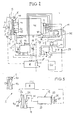
- ein schematisches Blockschaltbild eines hydraulischen Antriebskonzeptes der Maschine,
- Fig. 3
- eine Detailvariante zu
Fig. 2 , - Fig. 4
- ein Schaubild der kinematischen Viskosität eines Hydraulikmediums über der Betriebstemperatur, und
- Fig. 5
- eine schematische Seitenansicht einer anderen Maschine zum Verarbeiten von Einbaumaterial, nämlich eines Beschickers.
- Fig. 1
- 1 is a schematic side view of a self-propelled machine for processing paving material, namely a paver,
- Fig. 2
- a schematic block diagram of a hydraulic drive concept of the machine,
- Fig. 3
- a detail variant too
Fig. 2 . - Fig. 4
- a graph of the kinematic viscosity of a hydraulic medium above the operating temperature, and
- Fig. 5
- a schematic side view of another machine for processing paving material, namely a feeder.
Die Maschine F weist ein Chassis 32 mit einem in der gezeigten Ausführungsform Räder aufweisenden Fahrwerk 33 (alternativ ein Raupenfahrwerk) und einen Verbrennungsmotor M, z.B. einen Dieselmotor, als Primärantriebsquelle auf. Die Maschine besitzt eine Vielzahl Funktions- und Arbeitskomponenten, die überwiegend hydraulisch betrieben und von dem Verbrennungsmotor M mit Antriebsleistung versorgt werden. Auf dem Chassis 32 befindet sich ein Materialbunker 36, von dem sich im Chassis 32 eine Längsfördervorrichtung 37 zum hinteren Chassisende erstreckt, wo eine Querverteileinrichtung 38 mit einer Höhenverstellung 47 und einem Antrieb 39 angeordnet sind. Am Chassis 32 ist eine Einbaubohle 34 angelenkt, deren Anstellwinkel durch Nivellierzylinder 41 einstellbar und die durch Hydraulikzylinder 42 anhebbar ist. In der Einbaubohle sind Verstellzylinder 46, hydraulisch betriebene Tamper 44 und hydraulisch betriebene, optionale Pressleisten 45 vorgesehen. Für den Bunker 36 sind Bunkerwand-Verstellzylinder 41 vorgesehen. Dem Verbrennungsmotor M ist eine Kühlvorrichtung K zugeordnet, z.B. mit einem Mehrfeldkühler und einem Gebläse, das, beispielsweise, proportional zur Drehzahl des Verbrennungsmotors M angetrieben wird.The machine F has a
Die vorerwähnten Funktions- und Arbeitskomponenten der Maschine F werden zum Verarbeiten des Einbaumaterials mittels hydrostatischer Antriebseinheiten oder Zylinder betrieben. Hierfür ist wenigstens ein Hydraulikkreis H (
Damit das Hydraulikmedium möglichst rasch eine Betriebstemperatur von mindestens etwa 60°C, vorzugsweise zwischen etwa 75°C und 80°C oder geringfügig mehr, erreicht, und ein Hydraulikmedium-Betriebstemperaturbereich von beispielsweise 75°C bis 80°C im Normalbetrieb und unabhängig von Umgebungsklimakonditionen eingehalten werden, ist gemäß
In
An den Verbrennungsmotor M ist in
Der Verbrennungsmotor M ist auf einer Motorkonsole 17 angebracht, die über Motorlager 18 auf Widerlagern 19 des Chassis 32 der Maschine F schwingungsisoliert gelagert ist. Der Generator G, der beispielsweise (nicht gezeigt) vom Pumpenverteilergetriebe 5 aus angetrieben wird, kann auf der Motorkonsole 17 gelagert sein.The internal combustion engine M is mounted on a
In der gezeigten Ausführungsform in
An zumindest einer ausgewählten, oder an mehreren oder allen hydrostatischen Antriebseinheiten 7 bis 10 (bzw. den Pumpen 6) oder an anderen geeigneten Stellen des Hydraulikkreises H ist ein Temperatursensor 22 für die Betriebstemperatur des Hydraulikmediums (oder ein Sensor für den hydraulischen Belastungszustand) angeordnet und mit der Regelvorrichtung R verbunden. Ein solcher Temperatursensor 22 kann sich auch am oder im Reservoir 12 befinden, oder im oder beim Kühlbereich 1c. Ferner ist wenigstens ein Informationsgeber 23, z.B. ein Temperatur- und/oder Feuchtigkeitssensor, vorgesehen und an die Regelvorrichtung R angeschlossen, der das Umgebungsklima detektiert. Eine vorzugsweise computerisierte Hauptsteuerung CU der Maschine F kann ebenfalls an die Regelvorrichtung R angeschlossen (oder mit dieser vereinigt) sein und z.B. in Echtzeit oder vorbereitend Informationen i7 z.B. zum hydraulischen Belastungszustand der ausgewählten hydrostatischen Antriebseinheit 7 bereitstellen.On at least one selected, or on several or all hydrostatic drive units 7 to 10 (or the pump 6) or other suitable locations of the hydraulic circuit H, a
Die Hydraulikmedium-Betriebstemperatur-Einstell- und -Regelvorrichtung R weist eine Programmier- und/oder Setzsektion P auf, an der beispielsweise die gewünschte Betriebstemperatur des Hydraulikmediums eingestellt und überwacht werden kann, und, zweckmäßig, eine Auswahlvorrichtung W, an der eine Hydraulikmedium-Betriebstemperatur von mindestens etwa 60°C, vorzugsweise sogar etwa 75°C, einstellbar ist, auf die das Hydraulikmedium nach Betriebsaufnahme möglichst schnell gebracht werden soll, und ein Betriebstemperaturbereich im Normalbetrieb von mindestens etwa 60°C, vorzugsweise etwa 75°C bis 80°C, oder vorzugsweise sogar bis knapp 90°C, eingestellt werden kann, innerhalb dessen die Betriebstemperatur des Hydraulikmediums im Normalbetrieb der Maschine beim Verarbeiten des Einbaumaterials gehalten werden soll, unabhängig davon, wie das Kühlregelsystem S die Kühlung zumindest der Kühlflüssigkeit für den Verbrennungsmotor M regelt.The hydraulic medium operating temperature setting and regulating device R has a programming and / or setting section P at which, for example, the desired operating temperature of the hydraulic medium can be set and monitored, and, if appropriate, a selection device W, at which a hydraulic medium operating temperature of at least about 60 ° C, preferably even about 75 ° C, adjustable, to which the hydraulic medium after commissioning is to be brought as quickly as possible, and an operating temperature range in normal operation of at least about 60 ° C. , preferably about 75 ° C to 80 ° C, or preferably even up to almost 90 ° C, can be adjusted, within which the operating temperature of the hydraulic medium is to be maintained during normal operation of the machine during processing of the paving material, regardless of how the cooling control system S the Cooling at least the cooling liquid for the internal combustion engine M regulates.
In einem Kurzschlusskreis 28, beispielsweise zwischen dem Kühlbereich 1c und dem Reservoir 12 oder dem Hydraulikkreis H kann eine Zirkulationspumpe 29 eingesetzt sein.In a
Wegen des den Kühlbereichen 1a, 1b, 1c gemeinsam zugeordneten Gebläses 2 in
Im Betrieb der Maschine F und bei laufendem Verbrennungsmotor M wird die Betriebstemperatur des Hydraulikmediums im Hydraulikkreis H unabhängig vom Regeleingriff des Kühlregelsystems S zumindest für die Kühlflüssigkeit des Verbrennungsmotors M abhängig von hydraulischen Belastungssituationen im Hydraulikkreis, speziell an den Hydraulikpumpen 6 und/oder den hydrostatischen Antriebseinheiten 7 bis 10, vorzugsweise an einer ausgewählten Pumpe oder Antriebseinheit, von der z.B. die größte Antriebsleistung verbraucht werden oder bei der die stärksten Variationen auftreten, auf eine hinsichtlich der Viskosität des Hydraulikmediums optimale Betriebstemperatur von mindestens etwa 60°C gebracht, und dann in einem hinsichtlich der Viskosität optimalen Betriebstemperaturbereich von oberhalb etwa 60°C gehalten, um ein rasches Ansprechen der Hydraulikpumpen 6 und/oder hydrostatischen Antriebseinheiten 7 bis 10 zu gewährleisten, und Pumpverluste im Hydraulikkreis H zu minimieren, die der Verbrennungsmotor M mit zusätzlichem Brennstoffverbrauch kompensieren muss.During operation of the engine F and with the internal combustion engine M, the operating temperature of the hydraulic medium in the hydraulic circuit H is independent of the control intervention of the cooling control system S at least for the cooling liquid of the internal combustion engine M depending on hydraulic load situations in the hydraulic circuit, especially on the hydraulic pumps 6 and / or the hydrostatic drive units. 7 to 10, preferably at a selected pump or drive unit from which, for example, the largest drive power is consumed or in which the strongest variations occur, brought to an optimum in terms of viscosity of the hydraulic medium operating temperature of at least about 60 ° C, and then in a respect Viscosity optimum operating temperature range of above about 60 ° C held to ensure a rapid response of the hydraulic pumps 6 and / or hydrostatic drive units 7 to 10, and to minimize pumping losses in the hydraulic circuit H, the de r Compensate combustion engine M with additional fuel consumption.
Als weitere Detailvariante ist in
Das Schaubild in
Der in
Claims (15)
Priority Applications (6)
| Application Number | Priority Date | Filing Date | Title |
|---|---|---|---|
| DE502009000490T DE502009000490D1 (en) | 2009-06-29 | 2009-06-29 | Self-propelled machine |
| EP09008470.8A EP2282029B2 (en) | 2009-06-29 | 2009-06-29 | Self-propelled machine |
| AT09008470T ATE503092T1 (en) | 2009-06-29 | 2009-06-29 | SELF-PROPELLED MACHINE |
| US12/821,925 US20100326067A1 (en) | 2009-06-29 | 2010-06-23 | Self-propelled machine |
| CN2010102202512A CN101936211B (en) | 2009-06-29 | 2010-06-29 | Self-propelled machine |
| CN2010202491912U CN201794654U (en) | 2009-06-29 | 2010-06-29 | Self-driving machine |
Applications Claiming Priority (1)
| Application Number | Priority Date | Filing Date | Title |
|---|---|---|---|
| EP09008470.8A EP2282029B2 (en) | 2009-06-29 | 2009-06-29 | Self-propelled machine |
Publications (3)
| Publication Number | Publication Date |
|---|---|
| EP2282029A1 true EP2282029A1 (en) | 2011-02-09 |
| EP2282029B1 EP2282029B1 (en) | 2011-03-23 |
| EP2282029B2 EP2282029B2 (en) | 2022-04-20 |
Family
ID=41697972
Family Applications (1)
| Application Number | Title | Priority Date | Filing Date |
|---|---|---|---|
| EP09008470.8A Active EP2282029B2 (en) | 2009-06-29 | 2009-06-29 | Self-propelled machine |
Country Status (5)
| Country | Link |
|---|---|
| US (1) | US20100326067A1 (en) |
| EP (1) | EP2282029B2 (en) |
| CN (2) | CN201794654U (en) |
| AT (1) | ATE503092T1 (en) |
| DE (1) | DE502009000490D1 (en) |
Cited By (1)
| Publication number | Priority date | Publication date | Assignee | Title |
|---|---|---|---|---|
| DE102022111963A1 (en) | 2022-05-12 | 2023-11-16 | Dynapac Gmbh | Road construction machine |
Families Citing this family (13)
| Publication number | Priority date | Publication date | Assignee | Title |
|---|---|---|---|---|
| ATE503092T1 (en) * | 2009-06-29 | 2011-04-15 | Voegele Ag J | SELF-PROPELLED MACHINE |
| PL2530273T3 (en) * | 2011-06-01 | 2020-11-16 | Joseph Vögele AG | Construction machine with automatic ventilator rotation speed regulator |
| EP2578888B1 (en) | 2011-10-07 | 2018-12-05 | Joseph Vögele AG | Construction machine with automatic ventilator rotation speed regulator |
| CN103233947A (en) * | 2012-01-08 | 2013-08-07 | 钱荣华 | Method for cooling hydraulic oil of underground coal mine loader digger and other equipment |
| EP2672008B1 (en) * | 2012-06-05 | 2018-01-10 | Joseph Vögele AG | Road finisher and method for incorporating mixed goods with a road finisher |
| JP6009480B2 (en) * | 2014-03-06 | 2016-10-19 | 日立建機株式会社 | Cooling fan control device for construction machinery |
| US9382675B2 (en) | 2014-06-16 | 2016-07-05 | Caterpillar Paving Products Inc. | Electric powered systems for paving machines |
| WO2016056603A1 (en) * | 2014-10-10 | 2016-04-14 | 住友建機株式会社 | Asphalt finisher |
| CN104500716A (en) * | 2014-12-30 | 2015-04-08 | 戴纳派克(中国)压实摊铺设备有限公司 | Gear oil cooling system and pavement construction machine with same |
| EP3075909B1 (en) * | 2015-03-30 | 2017-09-06 | Joseph Vögele AG | Road construction machine with network for data transmission and use of a portion of a power line |
| EP3091125B1 (en) | 2015-05-06 | 2017-07-12 | Joseph Vögele AG | Construction machine with a lifting device for a feeding process and method of adjusting a tailgate |
| CN107407304B (en) * | 2015-05-26 | 2019-02-19 | 日立建机株式会社 | The engineering machinery and its pre-heating mean for having preheating unit |
| CN110725741A (en) * | 2019-10-15 | 2020-01-24 | 吉林大学 | Vehicle dual-cycle cooling system combined in parallel |
Citations (6)
| Publication number | Priority date | Publication date | Assignee | Title |
|---|---|---|---|---|
| US4785915A (en) | 1987-06-19 | 1988-11-22 | Westinghouse Electric Corp. | Elevator system monitoring cold oil |
| DE4439454A1 (en) | 1994-11-04 | 1996-05-09 | Man Takraf Foerdertechnik Gmbh | System for preheating of hydraulic circuits |
| US6076488A (en) | 1997-03-17 | 2000-06-20 | Shin Caterpillar Mitsubishi Ltd. | Cooling device for a construction machine |
| WO2006046902A1 (en) | 2004-10-27 | 2006-05-04 | Atlas Copco Rock Drills Ab | A drill rig and a method for controlling a fan therei |
| EP1741893A1 (en) | 2005-07-06 | 2007-01-10 | Kobelco Construction Machinery Co., Ltd. | Controlling system for cooling fan |
| EP1870576A1 (en) | 2005-04-07 | 2007-12-26 | Hitachi Construction Machinery Co., Ltd. | Cooling device for construction machine |
Family Cites Families (22)
| Publication number | Priority date | Publication date | Assignee | Title |
|---|---|---|---|---|
| US2306379A (en) * | 1930-03-12 | 1942-12-29 | Oscar Christianson | Hydraulic power system |
| FR1295419A (en) † | 1961-04-21 | 1962-06-08 | Richier Sa | Self-regulating cooler |
| GB988177A (en) * | 1962-03-09 | 1965-04-07 | Council Scient Ind Res | Improvements in hydraulic power transmission systems |
| DE2150710A1 (en) † | 1971-10-12 | 1973-04-19 | Gewerk Eisenhuette Westfalia | DEVICE FOR HEATING THE PRESSURE FLUID, IN PARTICULAR FLAME RESISTANT HYDRAULIC FLUIDS, FOR HYDRAULIC OPERATING SYSTEMS ETC. |
| GB1396778A (en) † | 1972-03-28 | 1975-06-04 | Af Hydraulics | Fluid supply systems |
| DE2502792C2 (en) † | 1975-01-24 | 1986-01-02 | Robert Bosch Gmbh, 7000 Stuttgart | Device for heating the hydraulic fluid of a hydrostatic circuit |
| US4811561A (en) * | 1986-04-08 | 1989-03-14 | Vickers, Incorporated | Power transmission |
| DE19634503B4 (en) † | 1996-08-26 | 2006-01-19 | Joseph Voegele Ag | pavers |
| US6378951B1 (en) † | 1997-07-23 | 2002-04-30 | Hydroacoustics, Inc. | Vibratory pavement breaker |
| SE509903C2 (en) † | 1998-02-27 | 1999-03-22 | Volvo Wheel Loaders Ab | Cooling and heating systems |
| US6195989B1 (en) † | 1999-05-04 | 2001-03-06 | Caterpillar Inc. | Power control system for a machine |
| US6463891B2 (en) † | 1999-12-17 | 2002-10-15 | Caterpillar Inc. | Twin fan control system and method |
| US6354089B1 (en) † | 2000-03-08 | 2002-03-12 | Case Corporation | Apparatus and method for cooling multiple fluids on a work vehicle |
| US6314950B1 (en) * | 2000-12-01 | 2001-11-13 | Caterpillar Inc. | Intake air temperature control system |
| US6845614B2 (en) * | 2001-01-05 | 2005-01-25 | Ingersoll-Rand Company | Hydraulic valve system |
| US6772714B2 (en) * | 2001-08-16 | 2004-08-10 | Deere & Company | Electronic fan control |
| JP3952972B2 (en) † | 2003-03-07 | 2007-08-01 | コベルコ建機株式会社 | Construction machine cooling system |
| CA2501917A1 (en) * | 2004-03-23 | 2005-09-23 | Hydra-Fab Fluid Power Inc. | Electro-hydraulic fan drive cooling and steering system for vehicle |
| DE102004038896A1 (en) † | 2004-08-11 | 2006-02-23 | Keller Grundbau Gmbh | Base plate pre-arrangement method, involves passing base plate through drill hole having smaller diameter, where deep floor plastering with larger diameter takes place under base plate |
| KR101021252B1 (en) * | 2005-12-27 | 2011-03-11 | 히다치 겡키 가부시키 가이샤 | Pump control device for hydraulic working machine, pump control method, and construction machine |
| DE202007005860U1 (en) † | 2007-04-21 | 2008-08-21 | Liebherr-Werk Bischofshofen Ges.M.B.H. | cooler system |
| ATE503092T1 (en) * | 2009-06-29 | 2011-04-15 | Voegele Ag J | SELF-PROPELLED MACHINE |
-
2009
- 2009-06-29 AT AT09008470T patent/ATE503092T1/en active
- 2009-06-29 EP EP09008470.8A patent/EP2282029B2/en active Active
- 2009-06-29 DE DE502009000490T patent/DE502009000490D1/en active Active
-
2010
- 2010-06-23 US US12/821,925 patent/US20100326067A1/en not_active Abandoned
- 2010-06-29 CN CN2010202491912U patent/CN201794654U/en not_active Expired - Lifetime
- 2010-06-29 CN CN2010102202512A patent/CN101936211B/en active Active
Patent Citations (6)
| Publication number | Priority date | Publication date | Assignee | Title |
|---|---|---|---|---|
| US4785915A (en) | 1987-06-19 | 1988-11-22 | Westinghouse Electric Corp. | Elevator system monitoring cold oil |
| DE4439454A1 (en) | 1994-11-04 | 1996-05-09 | Man Takraf Foerdertechnik Gmbh | System for preheating of hydraulic circuits |
| US6076488A (en) | 1997-03-17 | 2000-06-20 | Shin Caterpillar Mitsubishi Ltd. | Cooling device for a construction machine |
| WO2006046902A1 (en) | 2004-10-27 | 2006-05-04 | Atlas Copco Rock Drills Ab | A drill rig and a method for controlling a fan therei |
| EP1870576A1 (en) | 2005-04-07 | 2007-12-26 | Hitachi Construction Machinery Co., Ltd. | Cooling device for construction machine |
| EP1741893A1 (en) | 2005-07-06 | 2007-01-10 | Kobelco Construction Machinery Co., Ltd. | Controlling system for cooling fan |
Cited By (1)
| Publication number | Priority date | Publication date | Assignee | Title |
|---|---|---|---|---|
| DE102022111963A1 (en) | 2022-05-12 | 2023-11-16 | Dynapac Gmbh | Road construction machine |
Also Published As
| Publication number | Publication date |
|---|---|
| US20100326067A1 (en) | 2010-12-30 |
| EP2282029B2 (en) | 2022-04-20 |
| CN101936211B (en) | 2013-03-13 |
| ATE503092T1 (en) | 2011-04-15 |
| EP2282029B1 (en) | 2011-03-23 |
| CN201794654U (en) | 2011-04-13 |
| DE502009000490D1 (en) | 2011-05-05 |
| CN101936211A (en) | 2011-01-05 |
Similar Documents
| Publication | Publication Date | Title |
|---|---|---|
| EP2282029B1 (en) | Self-propelled machine | |
| EP2256248B2 (en) | Road finisher | |
| DE4327261C1 (en) | Coolant circuit | |
| EP2333157B1 (en) | Method for regulating the output of a road finisher or feeder and road finisher or feeder | |
| DE69834891T2 (en) | Cooling system for the internal combustion engine of a locomotive | |
| EP2420621B1 (en) | Paver and method for operating a paver | |
| DE3024209A1 (en) | Liq. cooling system for automobile engine with electronic control - regulating circulation pump or variable selective blocking element and by=pass line | |
| DE102007005391A1 (en) | Radiator arrangement for a drive train of a motor vehicle | |
| DE10334501A1 (en) | Vehicle internal combustion engine cooling system with variable speed water pump | |
| DE60025722T2 (en) | CONSTRUCTION MACHINE | |
| DE102014008749A1 (en) | BOTTOM MILLING MACHINE WITH COOLING SYSTEM, COOLING SYSTEM AND METHOD FOR COOLING A FLOOR MILLING MACHINE | |
| DE102005035121A1 (en) | Heating and air conditioning device operating method for e.g. passenger car, involves temporarily throttling coolant flow-rate in heating path, so that minimum heating criterion characterizing minimum heat potential is fulfillable | |
| EP2565334B1 (en) | Construction machine with oil-cooled generator | |
| DE102008011235A1 (en) | Temperature control system for fuel cells and method for controlling the temperature of fuel cells | |
| CN105556134A (en) | Implement carrier with improved control of hydraulic fluid supply | |
| EP0931209B1 (en) | Drive unit with a thermally regulated water pump | |
| EP2821551B1 (en) | Construction machine with heatable bearing structures | |
| DE102010051663A1 (en) | implement | |
| EP2333158B2 (en) | Road finisher | |
| DE102014106253A1 (en) | Heat exchanger assembly for a drive unit of a agricultural machine | |
| EP3418451B1 (en) | Tool with hydraulic drive for civil engineering work | |
| EP2774789A1 (en) | Heating device for a mobile working machine | |
| AT397375B (en) | SYSTEM FOR WARMING AN AIRCRAFT DEFROSTING LIQUID AND MOVING A DEFROSTING DEVICE | |
| DE102016015674A1 (en) | Paver. Control unit and method for operating a road paver | |
| DE3813669A1 (en) | Heat-pump installation |
Legal Events
| Date | Code | Title | Description |
|---|---|---|---|
| GRAP | Despatch of communication of intention to grant a patent |
Free format text: ORIGINAL CODE: EPIDOSNIGR1 |
|
| GRAS | Grant fee paid |
Free format text: ORIGINAL CODE: EPIDOSNIGR3 |
|
| PUAI | Public reference made under article 153(3) epc to a published international application that has entered the european phase |
Free format text: ORIGINAL CODE: 0009012 |
|
| 17P | Request for examination filed |
Effective date: 20100506 |
|
| AK | Designated contracting states |
Kind code of ref document: A1 Designated state(s): AT BE BG CH CY CZ DE DK EE ES FI FR GB GR HR HU IE IS IT LI LT LU LV MC MK MT NL NO PL PT RO SE SI SK TR |
|
| GRAA | (expected) grant |
Free format text: ORIGINAL CODE: 0009210 |
|
| STAA | Information on the status of an ep patent application or granted ep patent |
Free format text: STATUS: THE PATENT HAS BEEN GRANTED |
|
| AK | Designated contracting states |
Kind code of ref document: B1 Designated state(s): AT BE BG CH CY CZ DE DK EE ES FI FR GB GR HR HU IE IS IT LI LT LU LV MC MK MT NL NO PL PT RO SE SI SK TR |
|
| REG | Reference to a national code |
Ref country code: GB Ref legal event code: FG4D Free format text: NOT ENGLISH |
|
| RAP2 | Party data changed (patent owner data changed or rights of a patent transferred) |
Owner name: JOSEPH VOEGELE AG |
|
| REG | Reference to a national code |
Ref country code: CH Ref legal event code: EP |
|
| REG | Reference to a national code |
Ref country code: IE Ref legal event code: FG4D |
|
| REF | Corresponds to: |
Ref document number: 502009000490 Country of ref document: DE Date of ref document: 20110505 Kind code of ref document: P |
|
| REG | Reference to a national code |
Ref country code: DE Ref legal event code: R096 Ref document number: 502009000490 Country of ref document: DE Effective date: 20110505 |
|
| REG | Reference to a national code |
Ref country code: DE Ref legal event code: R081 Ref document number: 502009000490 Country of ref document: DE Owner name: JOSEPH VOEGELE AG, DE Free format text: FORMER OWNER: JOSEPH VOEGELE AG, 68163 MANNHEIM, DE Effective date: 20110329 |
|
| REG | Reference to a national code |
Ref country code: NL Ref legal event code: VDEP Effective date: 20110323 |
|
| PG25 | Lapsed in a contracting state [announced via postgrant information from national office to epo] |
Ref country code: SE Free format text: LAPSE BECAUSE OF FAILURE TO SUBMIT A TRANSLATION OF THE DESCRIPTION OR TO PAY THE FEE WITHIN THE PRESCRIBED TIME-LIMIT Effective date: 20110323 Ref country code: HR Free format text: LAPSE BECAUSE OF FAILURE TO SUBMIT A TRANSLATION OF THE DESCRIPTION OR TO PAY THE FEE WITHIN THE PRESCRIBED TIME-LIMIT Effective date: 20110323 Ref country code: LT Free format text: LAPSE BECAUSE OF FAILURE TO SUBMIT A TRANSLATION OF THE DESCRIPTION OR TO PAY THE FEE WITHIN THE PRESCRIBED TIME-LIMIT Effective date: 20110323 Ref country code: GR Free format text: LAPSE BECAUSE OF FAILURE TO SUBMIT A TRANSLATION OF THE DESCRIPTION OR TO PAY THE FEE WITHIN THE PRESCRIBED TIME-LIMIT Effective date: 20110624 Ref country code: LV Free format text: LAPSE BECAUSE OF FAILURE TO SUBMIT A TRANSLATION OF THE DESCRIPTION OR TO PAY THE FEE WITHIN THE PRESCRIBED TIME-LIMIT Effective date: 20110323 |
|
| LTIE | Lt: invalidation of european patent or patent extension |
Effective date: 20110323 |
|
| PG25 | Lapsed in a contracting state [announced via postgrant information from national office to epo] |
Ref country code: FI Free format text: LAPSE BECAUSE OF FAILURE TO SUBMIT A TRANSLATION OF THE DESCRIPTION OR TO PAY THE FEE WITHIN THE PRESCRIBED TIME-LIMIT Effective date: 20110323 Ref country code: NO Free format text: LAPSE BECAUSE OF FAILURE TO SUBMIT A TRANSLATION OF THE DESCRIPTION OR TO PAY THE FEE WITHIN THE PRESCRIBED TIME-LIMIT Effective date: 20110623 Ref country code: BG Free format text: LAPSE BECAUSE OF FAILURE TO SUBMIT A TRANSLATION OF THE DESCRIPTION OR TO PAY THE FEE WITHIN THE PRESCRIBED TIME-LIMIT Effective date: 20110623 Ref country code: SI Free format text: LAPSE BECAUSE OF FAILURE TO SUBMIT A TRANSLATION OF THE DESCRIPTION OR TO PAY THE FEE WITHIN THE PRESCRIBED TIME-LIMIT Effective date: 20110323 Ref country code: CY Free format text: LAPSE BECAUSE OF FAILURE TO SUBMIT A TRANSLATION OF THE DESCRIPTION OR TO PAY THE FEE WITHIN THE PRESCRIBED TIME-LIMIT Effective date: 20110323 |
|
| RAP2 | Party data changed (patent owner data changed or rights of a patent transferred) |
Owner name: JOSEPH VOEGELE AG |
|
| REG | Reference to a national code |
Ref country code: IE Ref legal event code: FD4D |
|
| PG25 | Lapsed in a contracting state [announced via postgrant information from national office to epo] |
Ref country code: PT Free format text: LAPSE BECAUSE OF FAILURE TO SUBMIT A TRANSLATION OF THE DESCRIPTION OR TO PAY THE FEE WITHIN THE PRESCRIBED TIME-LIMIT Effective date: 20110725 Ref country code: EE Free format text: LAPSE BECAUSE OF FAILURE TO SUBMIT A TRANSLATION OF THE DESCRIPTION OR TO PAY THE FEE WITHIN THE PRESCRIBED TIME-LIMIT Effective date: 20110323 |
|
| PG25 | Lapsed in a contracting state [announced via postgrant information from national office to epo] |
Ref country code: SK Free format text: LAPSE BECAUSE OF FAILURE TO SUBMIT A TRANSLATION OF THE DESCRIPTION OR TO PAY THE FEE WITHIN THE PRESCRIBED TIME-LIMIT Effective date: 20110323 Ref country code: ES Free format text: LAPSE BECAUSE OF FAILURE TO SUBMIT A TRANSLATION OF THE DESCRIPTION OR TO PAY THE FEE WITHIN THE PRESCRIBED TIME-LIMIT Effective date: 20110704 Ref country code: CZ Free format text: LAPSE BECAUSE OF FAILURE TO SUBMIT A TRANSLATION OF THE DESCRIPTION OR TO PAY THE FEE WITHIN THE PRESCRIBED TIME-LIMIT Effective date: 20110323 Ref country code: IS Free format text: LAPSE BECAUSE OF FAILURE TO SUBMIT A TRANSLATION OF THE DESCRIPTION OR TO PAY THE FEE WITHIN THE PRESCRIBED TIME-LIMIT Effective date: 20110723 |
|
| PLBI | Opposition filed |
Free format text: ORIGINAL CODE: 0009260 |
|
| PG25 | Lapsed in a contracting state [announced via postgrant information from national office to epo] |
Ref country code: NL Free format text: LAPSE BECAUSE OF FAILURE TO SUBMIT A TRANSLATION OF THE DESCRIPTION OR TO PAY THE FEE WITHIN THE PRESCRIBED TIME-LIMIT Effective date: 20110323 Ref country code: MT Free format text: LAPSE BECAUSE OF FAILURE TO SUBMIT A TRANSLATION OF THE DESCRIPTION OR TO PAY THE FEE WITHIN THE PRESCRIBED TIME-LIMIT Effective date: 20110323 |
|
| PLAB | Opposition data, opponent's data or that of the opponent's representative modified |
Free format text: ORIGINAL CODE: 0009299OPPO |
|
| BERE | Be: lapsed |
Owner name: JOSEPH VOGELE A.G. Effective date: 20110630 |
|
| 26 | Opposition filed |
Opponent name: BOMAC GMBH Effective date: 20111219 |
|
| PLAX | Notice of opposition and request to file observation + time limit sent |
Free format text: ORIGINAL CODE: EPIDOSNOBS2 |
|
| PG25 | Lapsed in a contracting state [announced via postgrant information from national office to epo] |
Ref country code: IE Free format text: LAPSE BECAUSE OF FAILURE TO SUBMIT A TRANSLATION OF THE DESCRIPTION OR TO PAY THE FEE WITHIN THE PRESCRIBED TIME-LIMIT Effective date: 20110323 |
|
| R26 | Opposition filed (corrected) |
Opponent name: BOMAG GMBH Effective date: 20111219 |
|
| PG25 | Lapsed in a contracting state [announced via postgrant information from national office to epo] |
Ref country code: PL Free format text: LAPSE BECAUSE OF FAILURE TO SUBMIT A TRANSLATION OF THE DESCRIPTION OR TO PAY THE FEE WITHIN THE PRESCRIBED TIME-LIMIT Effective date: 20110323 |
|
| REG | Reference to a national code |
Ref country code: DE Ref legal event code: R026 Ref document number: 502009000490 Country of ref document: DE Effective date: 20111219 |
|
| PG25 | Lapsed in a contracting state [announced via postgrant information from national office to epo] |
Ref country code: BE Free format text: LAPSE BECAUSE OF NON-PAYMENT OF DUE FEES Effective date: 20110630 |
|
| PLBB | Reply of patent proprietor to notice(s) of opposition received |
Free format text: ORIGINAL CODE: EPIDOSNOBS3 |
|
| PG25 | Lapsed in a contracting state [announced via postgrant information from national office to epo] |
Ref country code: MK Free format text: LAPSE BECAUSE OF FAILURE TO SUBMIT A TRANSLATION OF THE DESCRIPTION OR TO PAY THE FEE WITHIN THE PRESCRIBED TIME-LIMIT Effective date: 20110323 |
|
| PG25 | Lapsed in a contracting state [announced via postgrant information from national office to epo] |
Ref country code: MC Free format text: LAPSE BECAUSE OF NON-PAYMENT OF DUE FEES Effective date: 20110630 |
|
| PG25 | Lapsed in a contracting state [announced via postgrant information from national office to epo] |
Ref country code: LU Free format text: LAPSE BECAUSE OF NON-PAYMENT OF DUE FEES Effective date: 20110629 |
|
| PG25 | Lapsed in a contracting state [announced via postgrant information from national office to epo] |
Ref country code: TR Free format text: LAPSE BECAUSE OF FAILURE TO SUBMIT A TRANSLATION OF THE DESCRIPTION OR TO PAY THE FEE WITHIN THE PRESCRIBED TIME-LIMIT Effective date: 20110323 |
|
| PG25 | Lapsed in a contracting state [announced via postgrant information from national office to epo] |
Ref country code: HU Free format text: LAPSE BECAUSE OF FAILURE TO SUBMIT A TRANSLATION OF THE DESCRIPTION OR TO PAY THE FEE WITHIN THE PRESCRIBED TIME-LIMIT Effective date: 20110323 |
|
| REG | Reference to a national code |
Ref country code: CH Ref legal event code: PL |
|
| PG25 | Lapsed in a contracting state [announced via postgrant information from national office to epo] |
Ref country code: LI Free format text: LAPSE BECAUSE OF NON-PAYMENT OF DUE FEES Effective date: 20130630 Ref country code: CH Free format text: LAPSE BECAUSE OF NON-PAYMENT OF DUE FEES Effective date: 20130630 |
|
| PG25 | Lapsed in a contracting state [announced via postgrant information from national office to epo] |
Ref country code: RO Free format text: LAPSE BECAUSE OF FAILURE TO SUBMIT A TRANSLATION OF THE DESCRIPTION OR TO PAY THE FEE WITHIN THE PRESCRIBED TIME-LIMIT Effective date: 20110323 |
|
| REG | Reference to a national code |
Ref country code: AT Ref legal event code: MM01 Ref document number: 503092 Country of ref document: AT Kind code of ref document: T Effective date: 20140629 |
|
| PG25 | Lapsed in a contracting state [announced via postgrant information from national office to epo] |
Ref country code: AT Free format text: LAPSE BECAUSE OF NON-PAYMENT OF DUE FEES Effective date: 20140629 |
|
| APBM | Appeal reference recorded |
Free format text: ORIGINAL CODE: EPIDOSNREFNO |
|
| APBP | Date of receipt of notice of appeal recorded |
Free format text: ORIGINAL CODE: EPIDOSNNOA2O |
|
| APAH | Appeal reference modified |
Free format text: ORIGINAL CODE: EPIDOSCREFNO |
|
| APBQ | Date of receipt of statement of grounds of appeal recorded |
Free format text: ORIGINAL CODE: EPIDOSNNOA3O |
|
| REG | Reference to a national code |
Ref country code: FR Ref legal event code: PLFP Year of fee payment: 8 |
|
| REG | Reference to a national code |
Ref country code: FR Ref legal event code: PLFP Year of fee payment: 9 |
|
| REG | Reference to a national code |
Ref country code: FR Ref legal event code: PLFP Year of fee payment: 10 |
|
| APBU | Appeal procedure closed |
Free format text: ORIGINAL CODE: EPIDOSNNOA9O |
|
| PLAY | Examination report in opposition despatched + time limit |
Free format text: ORIGINAL CODE: EPIDOSNORE2 |
|
| PLBC | Reply to examination report in opposition received |
Free format text: ORIGINAL CODE: EPIDOSNORE3 |
|
| PLAB | Opposition data, opponent's data or that of the opponent's representative modified |
Free format text: ORIGINAL CODE: 0009299OPPO |
|
| R26 | Opposition filed (corrected) |
Opponent name: BOMAG GMBH Effective date: 20111219 |
|
| PUAH | Patent maintained in amended form |
Free format text: ORIGINAL CODE: 0009272 |
|
| STAA | Information on the status of an ep patent application or granted ep patent |
Free format text: STATUS: PATENT MAINTAINED AS AMENDED |
|
| 27A | Patent maintained in amended form |
Effective date: 20220420 |
|
| AK | Designated contracting states |
Kind code of ref document: B2 Designated state(s): AT BE BG CH CY CZ DE DK EE ES FI FR GB GR HR HU IE IS IT LI LT LU LV MC MK MT NL NO PL PT RO SE SI SK TR |
|
| REG | Reference to a national code |
Ref country code: DE Ref legal event code: R102 Ref document number: 502009000490 Country of ref document: DE |
|
| P01 | Opt-out of the competence of the unified patent court (upc) registered |
Effective date: 20230524 |
|
| PGFP | Annual fee paid to national office [announced via postgrant information from national office to epo] |
Ref country code: FR Payment date: 20230620 Year of fee payment: 15 Ref country code: DE Payment date: 20230629 Year of fee payment: 15 |
|
| PGFP | Annual fee paid to national office [announced via postgrant information from national office to epo] |
Ref country code: IT Payment date: 20230629 Year of fee payment: 15 Ref country code: GB Payment date: 20230619 Year of fee payment: 15 |