EP2281442A1 - Planting pots and multi-compartment tray having self-orienting configuration - Google Patents
Planting pots and multi-compartment tray having self-orienting configuration Download PDFInfo
- Publication number
- EP2281442A1 EP2281442A1 EP10012789A EP10012789A EP2281442A1 EP 2281442 A1 EP2281442 A1 EP 2281442A1 EP 10012789 A EP10012789 A EP 10012789A EP 10012789 A EP10012789 A EP 10012789A EP 2281442 A1 EP2281442 A1 EP 2281442A1
- Authority
- EP
- European Patent Office
- Prior art keywords
- pot
- tray
- compartment
- alignment
- pots
- Prior art date
- Legal status (The legal status is an assumption and is not a legal conclusion. Google has not performed a legal analysis and makes no representation as to the accuracy of the status listed.)
- Granted
Links
Images



Classifications
-
- A—HUMAN NECESSITIES
- A01—AGRICULTURE; FORESTRY; ANIMAL HUSBANDRY; HUNTING; TRAPPING; FISHING
- A01G—HORTICULTURE; CULTIVATION OF VEGETABLES, FLOWERS, RICE, FRUIT, VINES, HOPS OR SEAWEED; FORESTRY; WATERING
- A01G9/00—Cultivation in receptacles, forcing-frames or greenhouses; Edging for beds, lawn or the like
- A01G9/02—Receptacles, e.g. flower-pots or boxes; Glasses for cultivating flowers
-
- A—HUMAN NECESSITIES
- A01—AGRICULTURE; FORESTRY; ANIMAL HUSBANDRY; HUNTING; TRAPPING; FISHING
- A01G—HORTICULTURE; CULTIVATION OF VEGETABLES, FLOWERS, RICE, FRUIT, VINES, HOPS OR SEAWEED; FORESTRY; WATERING
- A01G9/00—Cultivation in receptacles, forcing-frames or greenhouses; Edging for beds, lawn or the like
- A01G9/006—Plant receptacles specially adapted as labels or label holders
-
- A—HUMAN NECESSITIES
- A01—AGRICULTURE; FORESTRY; ANIMAL HUSBANDRY; HUNTING; TRAPPING; FISHING
- A01G—HORTICULTURE; CULTIVATION OF VEGETABLES, FLOWERS, RICE, FRUIT, VINES, HOPS OR SEAWEED; FORESTRY; WATERING
- A01G9/00—Cultivation in receptacles, forcing-frames or greenhouses; Edging for beds, lawn or the like
- A01G9/02—Receptacles, e.g. flower-pots or boxes; Glasses for cultivating flowers
- A01G9/021—Pots formed in one piece; Materials used therefor
-
- A—HUMAN NECESSITIES
- A01—AGRICULTURE; FORESTRY; ANIMAL HUSBANDRY; HUNTING; TRAPPING; FISHING
- A01G—HORTICULTURE; CULTIVATION OF VEGETABLES, FLOWERS, RICE, FRUIT, VINES, HOPS OR SEAWEED; FORESTRY; WATERING
- A01G9/00—Cultivation in receptacles, forcing-frames or greenhouses; Edging for beds, lawn or the like
- A01G9/04—Flower-pot saucers
- A01G9/045—Trays for receiving multiple pots
Definitions
- the present invention relates to planting pots and a multi-compartment tray for holding same. More specifically, the present invention relates to planting pots and a multi-compartment tray having matching self-orienting configurations for aligning and locking the pots into position in the tray and for automatically orienting tags and other indicia in a uniform direction.
- Planting pots come in a variety of designs and configurations. Such pots are frequently used to plant flowers, vines, small shrubbery, and other types of plants. Often, planting pots include apertures located on the bottom portion thereof to allow drainage of water from soil packed into the pot and to allow aeration. Additionally, planting pots are often manufactured of lightweight, plastic materials that are suitable for temporary use by garden centers, gardeners, and the like.
- indicia e.g., logos or advertisements
- a multi-compartment tray and planting pots having a self-orienting configuration that automatically aligns and orients the pots when same are placed within the compartments of the tray.
- the present invention relates to planting pots and a multi-compartment tray, both having a self-orienting configuration for urging the pots into proper alignment when same are placed within the compartments of the tray.
- Each of the pots comprises an upper portion, a body portion, and a bottom portion.
- the bottom portion includes a center portion and a plurality of alignment recesses disposed radially about the center portion.
- Each of the plurality of alignment recesses include angled surfaces for coacting with the angled surfaces on the tray for urging the pot into a desired orientation when the pot is placed on the tray.
- a plurality of apertures are provided on the bottom portion for allowing drainage of water from soil in the pot and for providing aeration.
- Rails may be provided on the bottom portion for maintaining the pot a distance above the tray to allow water to drain from the apertures when the pot is positioned on the tray.
- the upper portion includes a plurality of slots that allow optional identification tags to be inserted therein for identifying the type of plant in the pot.
- the identification tags if provided, are oriented in a uniform direction when the pots are aligned on the tray.
- a multi-compartment tray for holding a plurality of planting pots.
- Each compartment of the tray includes an upper portion, a bottom portion, and a compartment wall therebetween.
- the bottom portion of each compartment includes a plurality of alignment protrusions disposed radially about a central portion.
- the alignment protrusions include angled surfaces that co-act with the angled surfaces of the alignment recesses of the pot to urge the pot into a desired orientation when the pot is placed in the compartment.
- a plurality of bevels located near the upper portion provide room for allowing insertion of the optional identification tags into the slots of the pots when the pots are positioned in the tray.
- the present invention relates to planting pots and a multi-compartment tray, each having a self-orienting configuration for urging the pots into proper alignment when same are placed within the compartments of the tray.
- the planting pots include angled recesses disposed radially about the bottom portion of the pots.
- the compartments of the tray include angled protrusions disposed radially about the bottom portion of the compartment. The angled recesses of the pot engage with the angled protrusions of the compartment when the pot is placed in the compartment to urge the pot into proper alignment.
- One or more slots may be included along an upper portion of each pot for allowing optional identification tags to be inserted thereinto. The identification tags, if included, are positioned by the self-orienting configuration of the pots and tray to face in a desired direction.
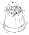
- FIG. 1 is an isometric view of a planting pot, generally indicated at 10, according to the present invention.
- the pot 10 comprises a body portion 20, an upper portion 30, and a bottom portion 40, forming a pot of a conventional shape as is known in the art.
- the upper portion 30 is connected to the body portion 20 by a shoulder 32, and includes a rim 36 connected to the shoulder 32.
- the upper portion 30 could include one or more slots 34 extending through the shoulder 32 for allowing identification tags to be inserted therethrough for identifying the type of plant contained in pot 10. Any number of slots and identification tags can be provided.
- the bottom portion 40 comprises a number of features that allow the pot 10 to be self-oriented when placed in a storage tray, such as the multi-compartment tray of the present invention discussed herein.
- a central portion 42 is disposed on the bottom portion 40, about which a plurality of alignment recesses 44 are disposed radially on the bottom portion 40 of the pot.
- the alignment recesses 44 are generally triangular in shape, and include angled and radial surfaces that co-act with alignment protrusions of the multi-compartment tray of the present invention to urge the pot 10 to rotate into proper alignment.
- a plurality of bevels 46 are provided near the circumference of the bottom portion 46 and include drainage apertures 48 to ensure proper drainage of water and other liquids from the pot 10 and to provide aeration of soil contained within the pot 10. Additionally, the apertures 48 are disposed about the flat surfaces of the bottom portion 40. Any configuration of the bevels 46 and drainage apertures 48 are considered within the scope of the present invention.
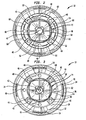
- FIG. 2 is a bottom view of the planting pot 10 of the present invention.
- the bottom portion 40 of the pot 10 includes a plurality of alignment recesses 44 disposed radially about the central portion 42 that co-act with alignment protrusions on the tray to urge the pot 10 to into proper alignment.
- Each of the alignment recesses 40 include angled surfaces 52 and 54, in addition to a radial surface 50, that are joined at edges to form a tapered or generally triangular configuration. Second radial surfaces 56 join the edges of the alignment recesses 44 to the circumference of the central portion 42.
- the weight of the pot 10 causes the surfaces 50, 52, and 54 to slide against the alignment protrusions, imparting a rotational force on the pot 10 as the pot moves downward. This rotational force urges the pot 10 into proper alignment, thus self-orienting the pot 10 when it is placed in the tray.
- a plurality of rails 60 can be provided on the bottom portion 40 to suspend the bottom portion 40 of the pot 10 a desired distance above a surface (e.g., above the bottom of a tray container). This prevents the apertures 48 of the pot 10 from being blocked, allowing drainage and aeration when the pot is in place.
- the rails 60 could be of any desired height and configuration.
- FIG. 3 is a top view of the planting pot 10 of the present invention.
- the body portion 20 of the pot 10 defines a cavity wherein soil and plants can be potted, as with conventional pots.
- the view of the bottom portion includes the same features as shown in the bottom view of FIG. 2 , though a recess shown in FIG. 2 is a protrusion in FIG. 3 .
- a plurality of protrusions 74 are formed by angled surfaces 64 and 66, and radial surface 62.
- the angled surfaces 64 and 66 and radial surface 62 are joined at edges to define generally triangular-shaped protrusions.
- the shoulder 32 of the pot 10 may include one or more slots 34 for allowing identification tags to be inserted therein.
- the identification tags can rest against the rim 36 of the pot 10 after insertion into the slots 34, allowing viewing from desired angles.
- tags are inserted into one or more desired slots 34, and when the pots are positioned in a multi-compartment tray and are self-oriented, the tags are automatically positioned to face in a uniform direction. This obviates the need to individually position each pot to face the tags in the same direction.
- indicia included on the sides of the pots such as artwork, text, logos, or other indicia, are automatically configured to face in a uniform direction, without requiring human intervention.
- FIG. 4 is a cross-sectional view of the planting pot of the present invention, taken along the line 4-4 of FIG. 1 .
- the entire pot 10 is preferably formed in a single, unitary construction of plastic typically utilized to manufacture conventional planting pots.
- the alignment recesses 44 can be formed using any suitable manufacturing process, such as molding. Any material can be utilized to form the planting pots and multi-compartment tray of the present invention, including, but not limited to, plastic or other polymeric material.
- FIG. 5 is an isometric view of the multi-compartment tray of the present invention, indicated generally at 100.
- the tray 100 comprises a plurality of compartments 110 for storing pots, such as the planting pot 10 of the present invention.
- the compartments 110 each comprise a body portion 120 and a bottom portion 140 having angled protrusions for aligning planting pots inserted in the compartments 110, as will hereinafter be discussed in greater detail.
- eight compartments 110 are provided on tray 100, but of course, any number of compartments could be provided.
- one or more carrying handles could be provided on the tray 100 to assist with lifting and transporting a plurality of pots.
- a plurality of trays 100 could be stacked on top of one another for storage.
- FIG. 6 is a partial isometric cross-sectional view showing one of the compartments 110 of the multi-compartment tray 100 in greater detail.
- the bottom portion 140 of the compartment 110 includes a center portion 142, about which a plurality of alignment protrusions 144 are disposed radially.
- Each of the alignment protrusions 144 includes angled surfaces 152 and 154, and radial surface 150, joined at edges to form a tapered protrusion.
- the bottom portion of a planting pot such as the bottom portion 40 of the planting pot 10 shown in FIGS. 1-4 and described earlier, is positioned against the alignment protrusions 144 when the pot 10 is inserted into the compartment 110.
- the pot 10 can be urged to orient in a desired direction by altering the angle at which the pot 10 falls into the compartment 110 of the tray 100.
- the pot 10 can be urged to self-orient to the right (e.g., twist to the right upon placement into the tray) if the pot 10 is dropped into the compartment 110 at an angle with reference to the normal of the tray 100.
- the pot 10 can be urged to self-orient to the left if the pot 10 is dropped into the compartment 110 at a different angle with reference to the normal of the tray 100.
- a channel 156 could optionally be provided to retain fluid drained from the pots inserted into the compartments. It is conceivable that one or more apertures could be provided on the channel 156 for allowing excess fluid to drain from both the pots and the compartments.
- the top portion 130 of the compartments 110 include a shoulder 132 upon which the shoulder 32 of the pot 10 can rest when placed in the compartment 110.
- the shoulder 132 and the upper part of the body portion 120 include bevels 138 for providing room for accommodating one or more identification tags inserted into the slots 34 of the pot 10 when the pot 10 is positioned in the compartment 110.
- the tags are self-oriented to face a uniform direction when the pot 10 is oriented by the alignment protrusions 144 and alignment recesses 44. This obviates the need for manually rotating the pots to face the tags in a uniform direction, and makes possible the automated (e.g., via an automated device in a conveyor line) placement of a plurality of pots into the tray 100.
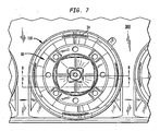
- FIG. 7 is a top view of the pot 10 of the present invention, positioned in a compartment 110 of the multi-compartment tray 100.
- the plurality of alignment recesses of the pot 10 co-act with the plurality of alignment protrusions of the compartment 110 to urge the pot 10 into proper alignment.
- one or more identification tags provided in the slots 34 are automatically configured to face in a uniform direction, without requiring human intervention to achieve such alignment. This results in a decrease in the amount of human labor required when assembling pots into trays, thereby reducing the costs associated with such labor.
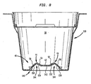
- FIG. 8 is a cross-sectional view of the planting pot and compartment of FIG. 7 , taken along the line 8-8.
- the alignment recesses 44 of the bottom surface 40 pot 10 co-act and mate with the alignment protrusions 144 of the bottom surface 140 of the compartment 110 to urge the pot 10 into proper alignment.
- the angled surfaces 52 and 54 of the recesses 44 in addition to the radial surfaces 50, slide against the angled surfaces 152 and 154 and radial surfaces 150 of the compartment 110 to urge the pot 10 into alignment when same is placed within the compartment 110.
- the central portion 42 of the pot 10 is centered above the central portion 142 of the compartment 110.
- FIG. 9 is a cross-sectional view of the planting pot and compartment of FIG. 7 , taken along the line 9-9. In this view, only a single alignment recess 44 and protrusion 144 is shown in cross-section. As can be seen, the angled surfaces 52 and 54 of the recess 44 co-act with the angled surfaces 152 and 154 of the recess 144 to urge the pot 10 into proper alignment when the pot 10 is placed in the compartment 110 of the multi-compartment tray of the present invention.
Landscapes
- Life Sciences & Earth Sciences (AREA)
- Environmental Sciences (AREA)
- Cultivation Receptacles Or Flower-Pots, Or Pots For Seedlings (AREA)
- Walking Sticks, Umbrellas, And Fans (AREA)
- Farming Of Fish And Shellfish (AREA)
Abstract
Description
- The present invention relates to planting pots and a multi-compartment tray for holding same. More specifically, the present invention relates to planting pots and a multi-compartment tray having matching self-orienting configurations for aligning and locking the pots into position in the tray and for automatically orienting tags and other indicia in a uniform direction.
- Planting pots come in a variety of designs and configurations. Such pots are frequently used to plant flowers, vines, small shrubbery, and other types of plants. Often, planting pots include apertures located on the bottom portion thereof to allow drainage of water from soil packed into the pot and to allow aeration. Additionally, planting pots are often manufactured of lightweight, plastic materials that are suitable for temporary use by garden centers, gardeners, and the like.
- It is known to provide trays for allowing a plurality of planting pots to be stored therein and carried thereby. Such trays allow a plurality of pots to be conveniently transported from one location to another, and also allow for plants of similar types to be grouped together. Further, pot trays are often used in combination with identification tags attached to portions of the pots to allow for quick grouping and identification of plants.
- A particular problem with existing planting pots, and trays used therewith, is that the pots are not capable of being automatically aligned and oriented when placed in trays. For example, when pots are provided with identification tags and are placed in the trays, one must manually shift the pots to orient same so that the identification tags are all facing in a desired direction. Moreover, even if identification tags are not used with the pots, existing pots require manual adjustment to properly orient the pots within the storage compartments of trays. Further, if indicia (e.g., logos or advertisements) are included on the pots, the pots must be manually configured to orient the indicia in a uniform direction and/or to improve visibility of same.
- Accordingly, what would be desirable, but has not heretofore been provided, is a multi-compartment tray and planting pots having a self-orienting configuration that automatically aligns and orients the pots when same are placed within the compartments of the tray.
- The present invention relates to planting pots and a multi-compartment tray, both having a self-orienting configuration for urging the pots into proper alignment when same are placed within the compartments of the tray. Each of the pots comprises an upper portion, a body portion, and a bottom portion. The bottom portion includes a center portion and a plurality of alignment recesses disposed radially about the center portion. Each of the plurality of alignment recesses include angled surfaces for coacting with the angled surfaces on the tray for urging the pot into a desired orientation when the pot is placed on the tray. A plurality of apertures are provided on the bottom portion for allowing drainage of water from soil in the pot and for providing aeration. Rails may be provided on the bottom portion for maintaining the pot a distance above the tray to allow water to drain from the apertures when the pot is positioned on the tray. The upper portion includes a plurality of slots that allow optional identification tags to be inserted therein for identifying the type of plant in the pot. The identification tags, if provided, are oriented in a uniform direction when the pots are aligned on the tray.
- A multi-compartment tray is provided for holding a plurality of planting pots. Each compartment of the tray includes an upper portion, a bottom portion, and a compartment wall therebetween. The bottom portion of each compartment includes a plurality of alignment protrusions disposed radially about a central portion. The alignment protrusions include angled surfaces that co-act with the angled surfaces of the alignment recesses of the pot to urge the pot into a desired orientation when the pot is placed in the compartment. A plurality of bevels located near the upper portion provide room for allowing insertion of the optional identification tags into the slots of the pots when the pots are positioned in the tray.
- These and other important objects and features of the invention will be apparent from the following Detailed Description of the Invention, taken in connection with the accompanying drawings, in which:
-
FIG. 1 is an isometric view of a planting pot according to the present invention. -
FIG. 2 is a bottom view of the planting pot ofFIG. 1 . -
FIG. 3 is a top view of the planting pot ofFIG. 1 . -
FIG. 4 is a cross-sectional view of the planting pot of the present invention, taken along the line 4-4 ofFIG. 1 . -
FIG. 5 is an isometric view of the multi-compartment tray of the present invention. -
FIG. 6 is a partial isometric cross-sectional view showing one of the compartments of the multi-compartment tray ofFIG. 5 in greater detail. -
FIG. 7 is a top view of the planting pot of the present invention positioned in a compartment of the multi-compartment tray. -
FIG. 8 is a cross-sectional view of the planting pot and compartment ofFIG. 7 , taken along the line 8-8. -
FIG. 9 is a cross-sectional view of the planting pot and compartment ofFIG. 7 , taken along the line 9-9. - The present invention relates to planting pots and a multi-compartment tray, each having a self-orienting configuration for urging the pots into proper alignment when same are placed within the compartments of the tray. The planting pots include angled recesses disposed radially about the bottom portion of the pots. The compartments of the tray include angled protrusions disposed radially about the bottom portion of the compartment. The angled recesses of the pot engage with the angled protrusions of the compartment when the pot is placed in the compartment to urge the pot into proper alignment. One or more slots may be included along an upper portion of each pot for allowing optional identification tags to be inserted thereinto. The identification tags, if included, are positioned by the self-orienting configuration of the pots and tray to face in a desired direction.
- Referring now to the drawings,
FIG. 1 is an isometric view of a planting pot, generally indicated at 10, according to the present invention. Thepot 10 comprises abody portion 20, anupper portion 30, and abottom portion 40, forming a pot of a conventional shape as is known in the art. Theupper portion 30 is connected to thebody portion 20 by ashoulder 32, and includes arim 36 connected to theshoulder 32. Theupper portion 30 could include one ormore slots 34 extending through theshoulder 32 for allowing identification tags to be inserted therethrough for identifying the type of plant contained inpot 10. Any number of slots and identification tags can be provided. - The
bottom portion 40 comprises a number of features that allow thepot 10 to be self-oriented when placed in a storage tray, such as the multi-compartment tray of the present invention discussed herein. Acentral portion 42 is disposed on thebottom portion 40, about which a plurality ofalignment recesses 44 are disposed radially on thebottom portion 40 of the pot. As will be discussed in greater detail below with reference toFIGS. 2-4, thealignment recesses 44 are generally triangular in shape, and include angled and radial surfaces that co-act with alignment protrusions of the multi-compartment tray of the present invention to urge thepot 10 to rotate into proper alignment. A plurality ofbevels 46 are provided near the circumference of thebottom portion 46 and includedrainage apertures 48 to ensure proper drainage of water and other liquids from thepot 10 and to provide aeration of soil contained within thepot 10. Additionally, theapertures 48 are disposed about the flat surfaces of thebottom portion 40. Any configuration of thebevels 46 anddrainage apertures 48 are considered within the scope of the present invention. -
FIG. 2 is a bottom view of the plantingpot 10 of the present invention. As mentioned previously, thebottom portion 40 of thepot 10 includes a plurality ofalignment recesses 44 disposed radially about thecentral portion 42 that co-act with alignment protrusions on the tray to urge thepot 10 to into proper alignment. Each of thealignment recesses 40 includeangled surfaces radial surface 50, that are joined at edges to form a tapered or generally triangular configuration. Secondradial surfaces 56 join the edges of thealignment recesses 44 to the circumference of thecentral portion 42. When thepot 10 is positioned in a compartment of a tray having alignment protrusions matching thealignment recesses 44, if the pot is not perfectly aligned, the weight of the pot 10 (or its contents) causes thesurfaces pot 10 as the pot moves downward. This rotational force urges thepot 10 into proper alignment, thus self-orienting thepot 10 when it is placed in the tray. - Optionally, a plurality of
rails 60 can be provided on thebottom portion 40 to suspend thebottom portion 40 of the pot 10 a desired distance above a surface (e.g., above the bottom of a tray container). This prevents theapertures 48 of thepot 10 from being blocked, allowing drainage and aeration when the pot is in place. Therails 60 could be of any desired height and configuration. -
FIG. 3 is a top view of the plantingpot 10 of the present invention. Thebody portion 20 of thepot 10 defines a cavity wherein soil and plants can be potted, as with conventional pots. The view of the bottom portion includes the same features as shown in the bottom view ofFIG. 2 , though a recess shown inFIG. 2 is a protrusion inFIG. 3 . Thus, a plurality ofprotrusions 74 are formed byangled surfaces radial surface 62. The angled surfaces 64 and 66 andradial surface 62 are joined at edges to define generally triangular-shaped protrusions. - The
shoulder 32 of thepot 10 may include one ormore slots 34 for allowing identification tags to be inserted therein. The identification tags can rest against therim 36 of thepot 10 after insertion into theslots 34, allowing viewing from desired angles. Preferably, when a plurality of pots are provided, tags are inserted into one or more desiredslots 34, and when the pots are positioned in a multi-compartment tray and are self-oriented, the tags are automatically positioned to face in a uniform direction. This obviates the need to individually position each pot to face the tags in the same direction. Additionally, indicia included on the sides of the pots, such as artwork, text, logos, or other indicia, are automatically configured to face in a uniform direction, without requiring human intervention. -
FIG. 4 is a cross-sectional view of the planting pot of the present invention, taken along the line 4-4 ofFIG. 1 . Theentire pot 10 is preferably formed in a single, unitary construction of plastic typically utilized to manufacture conventional planting pots. The alignment recesses 44 can be formed using any suitable manufacturing process, such as molding. Any material can be utilized to form the planting pots and multi-compartment tray of the present invention, including, but not limited to, plastic or other polymeric material. -
FIG. 5 is an isometric view of the multi-compartment tray of the present invention, indicated generally at 100. Thetray 100 comprises a plurality ofcompartments 110 for storing pots, such as the plantingpot 10 of the present invention. Thecompartments 110 each comprise abody portion 120 and abottom portion 140 having angled protrusions for aligning planting pots inserted in thecompartments 110, as will hereinafter be discussed in greater detail. As shown inFIG. 5 , eightcompartments 110 are provided ontray 100, but of course, any number of compartments could be provided. Optionally, one or more carrying handles could be provided on thetray 100 to assist with lifting and transporting a plurality of pots. Further, a plurality oftrays 100 could be stacked on top of one another for storage. -
FIG. 6 is a partial isometric cross-sectional view showing one of thecompartments 110 of themulti-compartment tray 100 in greater detail. Thebottom portion 140 of thecompartment 110 includes acenter portion 142, about which a plurality ofalignment protrusions 144 are disposed radially. Each of thealignment protrusions 144 includesangled surfaces radial surface 150, joined at edges to form a tapered protrusion. In operation, the bottom portion of a planting pot, such as thebottom portion 40 of the plantingpot 10 shown inFIGS. 1-4 and described earlier, is positioned against thealignment protrusions 144 when thepot 10 is inserted into thecompartment 110. If alignment is not perfect, gravitational force causes the surfaces of the alignment recesses 44 of thepot 10 to slide against the surfaces of thealignment protrusion 144. The sliding action of therecesses 44 against theprotrusions 144 imparts a rotational force against thepot 10, causing same to rotate as therecesses 44 slide down theprotrusions 144. The rotational force urges thepot 10 into alignment, thus self-orienting thepot 10. - The
pot 10 can be urged to orient in a desired direction by altering the angle at which thepot 10 falls into thecompartment 110 of thetray 100. For example, thepot 10 can be urged to self-orient to the right (e.g., twist to the right upon placement into the tray) if thepot 10 is dropped into thecompartment 110 at an angle with reference to the normal of thetray 100. Further, thepot 10 can be urged to self-orient to the left if thepot 10 is dropped into thecompartment 110 at a different angle with reference to the normal of thetray 100. - A
channel 156 could optionally be provided to retain fluid drained from the pots inserted into the compartments. It is conceivable that one or more apertures could be provided on thechannel 156 for allowing excess fluid to drain from both the pots and the compartments. Thetop portion 130 of thecompartments 110 include ashoulder 132 upon which theshoulder 32 of thepot 10 can rest when placed in thecompartment 110. Preferably, theshoulder 132 and the upper part of thebody portion 120 includebevels 138 for providing room for accommodating one or more identification tags inserted into theslots 34 of thepot 10 when thepot 10 is positioned in thecompartment 110. Importantly, when identification tags are utilized with present invention, the tags are self-oriented to face a uniform direction when thepot 10 is oriented by thealignment protrusions 144 and alignment recesses 44. This obviates the need for manually rotating the pots to face the tags in a uniform direction, and makes possible the automated (e.g., via an automated device in a conveyor line) placement of a plurality of pots into thetray 100. -
FIG. 7 is a top view of thepot 10 of the present invention, positioned in acompartment 110 of themulti-compartment tray 100. The plurality of alignment recesses of thepot 10 co-act with the plurality of alignment protrusions of thecompartment 110 to urge thepot 10 into proper alignment. By urging the pot into alignment, one or more identification tags provided in theslots 34 are automatically configured to face in a uniform direction, without requiring human intervention to achieve such alignment. This results in a decrease in the amount of human labor required when assembling pots into trays, thereby reducing the costs associated with such labor. -
FIG. 8 is a cross-sectional view of the planting pot and compartment ofFIG. 7 , taken along the line 8-8. The alignment recesses 44 of thebottom surface 40pot 10 co-act and mate with thealignment protrusions 144 of thebottom surface 140 of thecompartment 110 to urge thepot 10 into proper alignment. The angled surfaces 52 and 54 of therecesses 44, in addition to the radial surfaces 50, slide against theangled surfaces radial surfaces 150 of thecompartment 110 to urge thepot 10 into alignment when same is placed within thecompartment 110. Thecentral portion 42 of thepot 10 is centered above thecentral portion 142 of thecompartment 110. -
FIG. 9 is a cross-sectional view of the planting pot and compartment ofFIG. 7 , taken along the line 9-9. In this view, only asingle alignment recess 44 andprotrusion 144 is shown in cross-section. As can be seen, theangled surfaces recess 44 co-act with theangled surfaces recess 144 to urge thepot 10 into proper alignment when thepot 10 is placed in thecompartment 110 of the multi-compartment tray of the present invention. - Having thus described the invention in detail, it is to be understood that the foregoing description is not intended to limit the spirit and scope thereof. What is desired to be protected by Letters Patent is set forth in the appended claims.
Claims (15)
- A method for orienting a planting pot comprising:positioning a planting pot, having one or more alignment recesses on a bottom portion of the pot, above a compartment of a tray, the tray having a plurality of compartments, each compartment having one or more alignment protrusions on a bottom portion of the compartment;releasing the pot; andallowing the pot to move in a downward direction such that the weight of the pot causes the one or more alignment recesses to contact and slide along the one or more alignment protrusions along a horizontal direction and a vertical direction to orient the pot into the tray.
- The method of Claim 1, wherein the planting pot has indicia on at least one side and step of allowing the pot to move in a downward direction orients the indicia to face in a desired direction.
- The method of Claim 1, wherein the planting pot has a tag slot on at least one side and step of allowing the pot to move in a downward direction orients the tag slot to face in a desired direction.
- The method of Claim 3, wherein the pot is urged into alignment when the pot is positioned in the compartment.
- The method of Claim 4, wherein the step of positioning the pot in a compartment of a tray comprises placing the pot in the compartment without having to align the one or more alignment recesses with the one or more alignment protrusions.
- The method of Claim 5, further comprising the step of inserting an identification tag into the tag slot of a shoulder of the pot.
- The method of Claim 6, wherein the identification tag is automatically oriented when the pot is urged into a desired configuration.
- The method of Claim 1, wherein the one or more alignment protrusions are disposed radially on a bottom portion of the compartment, and the one or more protrusions include first and second sloped surfaces.
- The method of Claim 8, wherein the pot is oriented in a generally forward facing direction in the tray.
- The method of Claim 1, wherein the step of positioning the pot comprises positioning a forward face of the pot in misalignment with a forward face of the tray, the misalignment being less than 45 degrees out of alignment, the one or more recesses and the one or more protrusions sliding along each other in a horizontal and vertical direction to orient the pot in the tray.
- The method of Claim 1, wherein the one or more recesses includes first and second angled surfaces joined at a radially oriented upper end.
- The method of Claim 11, wherein the one or more alignment protrusions includes first and second angled surfaces joined at a radially oriented upper end.
- The method of Claim 12, wherein the step of allowing the pot to move in a downward direction comprises allowing the pot to move in a downward direction such that the weight of the pot causes the angled surfaces of the one or more alignment recesses of the pot to contact and slide along the angled surfaces of the one or more alignment protrusions of the tray to align the pot in a desired direction with respect to the tray.
- The method of Claim 13, wherein the step of allowing the angled surfaces of the one or more alignment recesses of the pot to contact and slide along the angled surfaces of the one or more alignment protrusions of the tray comprises allowing the weight of the pot to cause the angled surfaces of the one or more alignment recesses to slide against the angled surfaces of the one or more alignment protrusions along a horizontal direction and a vertical direction to align the pot in a desired direction with respect to the tray.
- The method of Claim 2, wherein the planting pot has a tag slot on at least one side and step of allowing the pot to move in a downward direction orients the tag slot to face in a desired direction with respect to the tray.
Applications Claiming Priority (2)
| Application Number | Priority Date | Filing Date | Title |
|---|---|---|---|
| US10/423,476 US7454864B2 (en) | 2003-04-25 | 2003-04-25 | Planting pots and multi-compartment tray having self-orienting configuration |
| EP03786851A EP1622445B1 (en) | 2003-04-25 | 2003-11-19 | Planting pots and multi-compartment tray having self-orienting configuration |
Related Parent Applications (2)
| Application Number | Title | Priority Date | Filing Date |
|---|---|---|---|
| EP03786851.0 Division | 2003-11-19 | ||
| EP03786851A Division EP1622445B1 (en) | 2003-04-25 | 2003-11-19 | Planting pots and multi-compartment tray having self-orienting configuration |
Publications (2)
| Publication Number | Publication Date |
|---|---|
| EP2281442A1 true EP2281442A1 (en) | 2011-02-09 |
| EP2281442B1 EP2281442B1 (en) | 2012-09-26 |
Family
ID=33299131
Family Applications (2)
| Application Number | Title | Priority Date | Filing Date |
|---|---|---|---|
| EP10012789A Expired - Lifetime EP2281442B1 (en) | 2003-04-25 | 2003-11-19 | Planting pots and multi-compartment tray having self-orienting configuration |
| EP03786851A Expired - Lifetime EP1622445B1 (en) | 2003-04-25 | 2003-11-19 | Planting pots and multi-compartment tray having self-orienting configuration |
Family Applications After (1)
| Application Number | Title | Priority Date | Filing Date |
|---|---|---|---|
| EP03786851A Expired - Lifetime EP1622445B1 (en) | 2003-04-25 | 2003-11-19 | Planting pots and multi-compartment tray having self-orienting configuration |
Country Status (9)
| Country | Link |
|---|---|
| US (4) | US7454864B2 (en) |
| EP (2) | EP2281442B1 (en) |
| JP (2) | JP2006524488A (en) |
| AT (1) | ATE495662T1 (en) |
| AU (1) | AU2003295650B2 (en) |
| DE (1) | DE60335831D1 (en) |
| DK (2) | DK1622445T3 (en) |
| ES (2) | ES2359971T3 (en) |
| WO (1) | WO2004095905A2 (en) |
Cited By (3)
| Publication number | Priority date | Publication date | Assignee | Title |
|---|---|---|---|---|
| WO2022058987A1 (en) * | 2020-09-21 | 2022-03-24 | Nuova Pasquini & Bini S.P.A. | Flower pot |
| IT202200013051A1 (en) * | 2022-06-21 | 2023-12-21 | Nuova Pasquini & Bini S P A | CONTAINER FOR FLORISTRY |
| IT202200013042A1 (en) * | 2022-06-21 | 2023-12-21 | Nuova Pasquini & Bini S P A | CONTAINER FOR FLORISTRY |
Families Citing this family (48)
| Publication number | Priority date | Publication date | Assignee | Title |
|---|---|---|---|---|
| US7454864B2 (en) | 2003-04-25 | 2008-11-25 | Smith Thomas J | Planting pots and multi-compartment tray having self-orienting configuration |
| US7681357B2 (en) * | 2005-01-25 | 2010-03-23 | Dyas Drew C | Apparatuses and systems for growing nursery stock |
| WO2007044011A1 (en) * | 2005-10-13 | 2007-04-19 | Burgess & Burgess. Inc. | Modular bucket system for displaying fresh cut flowers |
| US7624536B2 (en) * | 2006-04-27 | 2009-12-01 | Landmark Plastic Corporation | Container with plant identification tag slot |
| GB2453094B (en) * | 2006-07-03 | 2011-02-16 | John Rodney Keats | Stackable plant pot |
| ITPD20060422A1 (en) * | 2006-11-14 | 2008-05-15 | Luca Stragapede | CONTAINER STRUCTURE INHIBITOR TO INHIBIT INSULATION PROLIFERATION IN A LIQUID BODY, AN INHIBITABLE INHIBITOR DEVICE IN A CONTAINMENT BODY AND METHOD OF ASSEMBLING SUCH A DEVICE SUCH AS A CONTAINMENT BODY TO MAKE T |
| US10412902B2 (en) * | 2007-03-19 | 2019-09-17 | A To Z Van Wingerden And Associates, Llc | Planter, planting and method of growing plants |
| US20080263943A1 (en) * | 2007-04-27 | 2008-10-30 | Werner Sperzel | Coordinated Flat Talkers and Plant Tags and Method of Communicating Pertinent Plant Criteria |
| DE202007014037U1 (en) * | 2007-10-08 | 2009-03-19 | Pöppelmann Holding GmbH & Co. KG | Plant pot made of plastic |
| US20090241417A1 (en) * | 2008-03-29 | 2009-10-01 | Smith Thomas J | Open Bottomed Planting Pot with Releaseable Bottom Cover |
| US20110056131A1 (en) * | 2008-04-18 | 2011-03-10 | Smith Thomas J | Self-orientating plant pot and tray system |
| US20090260285A1 (en) * | 2008-04-18 | 2009-10-22 | Smith Thomas J | Self-orientating plant pot and tray system |
| USD598809S1 (en) | 2008-04-18 | 2009-08-25 | Smith Thomas J | Plant pots and tray combination |
| DE202008008356U1 (en) * | 2008-06-24 | 2009-11-12 | Pöppelmann Holding GmbH & Co. KG | Pflanztopf |
| USD606422S1 (en) * | 2008-08-05 | 2009-12-22 | Poeppelmann Holding Gmbh & Co. Kg | Tray with multiple separate spaces for plant pots |
| EP2490521B1 (en) * | 2009-10-20 | 2020-06-17 | Jørn Hansen | Self-watering system for a potted plant |
| USD624846S1 (en) * | 2009-11-02 | 2010-10-05 | Poeppelmann Holding Gmbh & Co. Kg | Tray with multiple separate spaces for plants |
| US8627599B2 (en) | 2010-09-22 | 2014-01-14 | Costa Farms, LLC | Planting pot display system |
| DE202010015471U1 (en) * | 2010-11-17 | 2012-02-20 | Pöppelmann Holding GmbH & Co. KG | Pot display for plant pots |
| USD666524S1 (en) * | 2010-12-17 | 2012-09-04 | Kaneya Co., Ltd | Plant pot |
| NL2006366C2 (en) * | 2011-03-10 | 2012-09-11 | Dorp Cdp B V Van | HOLDER FOR PLANT POTS. |
| NL2008780C2 (en) * | 2012-05-09 | 2013-11-12 | Voskamp Vollebregt Holding B V | PLANT POT WITH RAISED BOTTOM. |
| US20130318872A1 (en) | 2012-06-01 | 2013-12-05 | Patentstar B.V. | Plant pot assembly |
| EP2668841B1 (en) | 2012-06-01 | 2016-06-22 | Patentstar BV | Plant pot and carrier assembly |
| ES2473715B1 (en) * | 2012-08-30 | 2015-04-13 | Carlos FERRANDO GARCÍA | CRASH HELMET |
| CA151290S (en) | 2012-12-07 | 2014-04-02 | Patentstar B V | Plant pot |
| US9338948B2 (en) | 2012-12-18 | 2016-05-17 | East Jordan Plastics, Inc. | Plant pot holder tray |
| CA2903070C (en) * | 2013-03-04 | 2021-02-16 | Poppin Pods Australia Pty Ltd | Living plant display and storage system, apparatus and method |
| USD745429S1 (en) * | 2013-07-18 | 2015-12-15 | Patrick John Morris | Planter |
| USD745428S1 (en) * | 2013-07-18 | 2015-12-15 | Patrick John Morris | Planter |
| NL2011918C2 (en) * | 2013-12-09 | 2015-06-11 | Houdstermij Modiform B V | Plant tray, assembly of a tray and at least one plant pot, method for assembling an assembly, and method for handling plant pots. |
| USD787148S1 (en) | 2014-07-08 | 2017-05-16 | Poppelmann Holding Gmbh & Co. Kg | Forklift-tray |
| US10076085B2 (en) | 2015-01-26 | 2018-09-18 | Plantlogic LLC | Stackable pots for plants |
| CN104584941A (en) * | 2015-03-01 | 2015-05-06 | 李志峰 | Cultivator for raising flower seedlings |
| DE202015103641U1 (en) * | 2015-07-10 | 2016-10-11 | Pöppelmann Holding GmbH & Co. KG | Pflanzentray |
| US11083144B2 (en) * | 2015-10-30 | 2021-08-10 | Syngenta Participations Ag | Plant container and tray system |
| PE20171148A1 (en) * | 2016-01-27 | 2017-08-14 | Plantlogic LLC | DRAINAGE CAPTURE POTS FOR PLANTS |
| CA2972783C (en) * | 2016-07-10 | 2025-12-23 | The Hc Companies, Inc. | Horticultural container with tag slot |
| USD827486S1 (en) * | 2016-07-10 | 2018-09-04 | The Hc Companies, Inc. | Tag slot |
| CA3202721A1 (en) | 2017-03-16 | 2018-09-16 | East Jordan Plastics, Inc. | Planting pot and tray system and method |
| USD813719S1 (en) * | 2017-03-22 | 2018-03-27 | The Hc Companies, Inc. | Planter |
| DE202018000954U1 (en) * | 2018-02-22 | 2019-05-23 | Pöppelmann Holding GmbH & Co. KG | Pflanzentray |
| US11343975B2 (en) * | 2018-10-30 | 2022-05-31 | Thomsen Sas | Pot for culturing an epiphyte and epiphyte potted therein |
| USD909907S1 (en) * | 2019-08-23 | 2021-02-09 | Xiao Dan Liu | Flower pot |
| US11083145B1 (en) | 2020-11-21 | 2021-08-10 | Richard J Eisen | Planter system |
| USD927350S1 (en) * | 2020-12-03 | 2021-08-10 | Danjing Zhan | Nursery pot |
| WO2026069220A1 (en) * | 2024-09-27 | 2026-04-02 | Nuova Pasquini & Bini S.P.A. | Container for growing raspberry |
| US20260114383A1 (en) * | 2024-10-25 | 2026-04-30 | Lucy A. Mitchell | Planter transport tray having removal means |
Citations (4)
| Publication number | Priority date | Publication date | Assignee | Title |
|---|---|---|---|---|
| US3965616A (en) * | 1974-12-30 | 1976-06-29 | Ridgeway John C | Lockable vegetation pot and saucer |
| US5022183A (en) * | 1989-07-31 | 1991-06-11 | Kord Products Limited | Flower pot carrying tray with restraining means for plural pots |
| FR2698921A1 (en) * | 1992-12-09 | 1994-06-10 | Soparco Sa | Assembly fixture for orienting two parts to be assembled with view to automation of operation - includes two complementary conical forms one male and other female which are engaged male inside female part to ensure correct orientation every time |
| EP0842599A1 (en) * | 1996-11-14 | 1998-05-20 | Bernard Grigi | Horticultural container |
Family Cites Families (113)
| Publication number | Priority date | Publication date | Assignee | Title |
|---|---|---|---|---|
| CA104670A (en) | 1907-01-02 | 1907-04-16 | Oscar Geisel | Automobile agricultural vehicle |
| CA111697A (en) | 1907-04-08 | 1908-05-05 | The Royden Marble Machinery Company | Marble moulding machine |
| US1057877A (en) | 1912-08-27 | 1913-04-01 | John Morton Peeples | Seed-tester. |
| US1391353A (en) | 1920-08-21 | 1921-09-20 | Russell D Wells | Flowerpot or other vessel |
| US1606523A (en) | 1924-05-05 | 1926-11-09 | Clark E Gardner | Potted-bulb package |
| US1850369A (en) * | 1930-03-21 | 1932-03-22 | P L Andrews Corp | Bottle label and pocket member |
| US1904788A (en) | 1932-06-08 | 1933-04-18 | Thomas Young Nurseries Inc | Display of cut flowers |
| US2661574A (en) | 1950-11-28 | 1953-12-08 | Alexander S Ritter | Potted plant package |
| US2700847A (en) | 1951-05-03 | 1955-02-01 | Eugene L Brasol | Flowerpot |
| US3142133A (en) * | 1962-01-22 | 1964-07-28 | Ralph P Brooks | Planter |
| DE2113499A1 (en) * | 1971-03-19 | 1972-09-21 | Guenter Noethen | Flower pot grid |
| US3762097A (en) | 1971-03-30 | 1973-10-02 | J Gallo | Carrier with retaining rollers |
| US3852912A (en) | 1972-09-01 | 1974-12-10 | K Diller | Shipping and carrying container for pots |
| US3866351A (en) * | 1973-05-25 | 1975-02-18 | Green Island International Inc | Potted plant display devices |
| US3896587A (en) * | 1973-06-25 | 1975-07-29 | Charles J Insalaco | Nursery pot having improved drainage |
| BE814369A (en) | 1974-04-30 | 1974-08-16 | PACKAGING FOR FLOWER PIECES. | |
| US4528774A (en) | 1974-09-06 | 1985-07-16 | Vivian A. Skaife | Plant and seed growing system |
| USD243112S (en) * | 1974-11-11 | 1977-01-18 | Ronald John Gross | Plant container |
| US4057931A (en) | 1974-11-20 | 1977-11-15 | National Polymers, Inc. | Stackable flower pot |
| US3951259A (en) * | 1975-03-12 | 1976-04-20 | Anchor Hocking Corporation | Package for tumblers and the like |
| JPS51115145A (en) | 1975-03-27 | 1976-10-09 | Koukin Riyuu | Clock study toy |
| US4050579A (en) * | 1976-11-01 | 1977-09-27 | Arenco Machine Company, Inc. | Package for orienting a plurality of articles |
| US4160342A (en) | 1977-07-01 | 1979-07-10 | Canaird Sales Ltd. | Pots for growing plants |
| US4173097A (en) * | 1977-09-14 | 1979-11-06 | Staby George L | Container with raised indentations for aeration and drainage |
| US4167080A (en) | 1977-11-11 | 1979-09-11 | Mickelson Richard C | Planter having self-indexing drain dish |
| USD255410S (en) | 1979-05-03 | 1980-06-17 | Dart Industries Inc. | Planter or the like |
| US4407092A (en) | 1979-07-20 | 1983-10-04 | Ware R Louis | Hydroponic assembly and wafer for use therein |
| US4296569A (en) * | 1979-10-22 | 1981-10-27 | Illinois Tool Works Inc. | Nestable and stackable transplanting system |
| FR2467540A1 (en) | 1979-10-19 | 1981-04-30 | Illinois Tool Works | PLANTATION DEVICE AND SYSTEM FOR CULTIVATION OF PLANTS TO BE REPLACED |
| US4242834A (en) * | 1979-10-19 | 1981-01-06 | Illinois Tool Works Inc. | Nestable and stackable transplanting system |
| US4315382A (en) | 1979-11-26 | 1982-02-16 | Phillips Petroleum Co. | Plant container |
| GB2069804B (en) * | 1980-02-26 | 1983-06-02 | Bohill A | Plant pot holder |
| JPS58146447A (en) | 1982-02-25 | 1983-09-01 | Sakai Chem Ind Co Ltd | Catalyst regeneration method |
| US4495725A (en) | 1984-03-12 | 1985-01-29 | Talbott Gene B | Seed germinating apparatus and method |
| US4618069A (en) * | 1984-03-21 | 1986-10-21 | Paul Quong | Shipping-and-storage container |
| US4567981A (en) | 1984-08-10 | 1986-02-04 | Cda Industries Inc. | Display packaging system |
| JPS61148161U (en) | 1985-03-05 | 1986-09-12 | ||
| US4700837A (en) * | 1985-11-15 | 1987-10-20 | International Container Systems, Inc. | Universal bottle case |
| US4658542A (en) | 1986-02-24 | 1987-04-21 | Holmberg Douglas A | Portable growing system |
| USD305738S (en) | 1986-05-02 | 1990-01-30 | The Coca-Cola Company | Tier sheet for a display module |
| US4759451A (en) | 1986-06-25 | 1988-07-26 | Rehrig-Pacific Company, Inc. | Multi-level-stacking/nesting tray |
| US4739581A (en) * | 1986-12-12 | 1988-04-26 | Jarvis Eugene R | Flower pot |
| US4911300A (en) | 1987-07-27 | 1990-03-27 | Ralph Colonna | Container packaging system |
| JPS6474743A (en) | 1987-09-17 | 1989-03-20 | Fujitsu Ltd | Device and process for manufacturing semiconductor device |
| US4928841A (en) * | 1988-05-13 | 1990-05-29 | Scepter Manufacturing Company Limited | Bottle tray |
| US4887388A (en) * | 1988-10-19 | 1989-12-19 | Waltel Jr Joseph | Irrigation system for commercial plant cultivation |
| US4941572A (en) | 1989-05-24 | 1990-07-17 | Jetram Sales, Inc. | Method and package for fresh cut flower arrangements and plants |
| US4962855A (en) * | 1989-05-25 | 1990-10-16 | T. O. Plastics, Inc. | System for loading thin-walled plastic flower pots onto a loading tray |
| FR2649582B1 (en) | 1989-07-17 | 1991-10-18 | Redoute Catalogue Sa | PACKAGING FOR Potted Plants |
| USD323415S (en) | 1989-07-17 | 1992-01-21 | Iverson Perennial Gardens, Inc. | Tray for plant pots or the like |
| USD322707S (en) | 1989-07-17 | 1991-12-24 | Iverson Perennial Gardens, Inc. | Tray for plant pots or the like |
| USD323416S (en) | 1989-07-17 | 1992-01-21 | Iverson Perennial Gardens, Inc. | Tray for plant pots or the like |
| US5117581A (en) | 1990-12-04 | 1992-06-02 | State Of Oregon Acting By And Through The Oregon State Board Of Higher Education On Behalf Of Oregon State Universities | Pallet system for container-grown plants |
| GB2263052B (en) | 1991-05-10 | 1994-06-22 | Cookson Plantpak Ltd | Multi-cell plant containers |
| US5141149A (en) | 1991-08-05 | 1992-08-25 | Fulton J Scott | Multiple use plant shipping and display container |
| US5180052A (en) * | 1991-09-06 | 1993-01-19 | Chesapeake Display And Packaging Company | Display tray |
| NZ244509A (en) * | 1991-09-30 | 1996-01-26 | David Victor Hawthorne | Plant pot with special shape to encourage structurally sound root formations |
| WO1993019446A1 (en) | 1992-03-25 | 1993-09-30 | Design Development Group Pty. Ltd. | Plant id tag and pot |
| JPH05308853A (en) | 1992-05-08 | 1993-11-22 | Fukukyu Hen | Stacking type cultivation container |
| US5315786A (en) | 1992-05-14 | 1994-05-31 | Thomas Smith | Planting tray |
| JP3063407B2 (en) | 1992-08-06 | 2000-07-12 | ヤマハ株式会社 | Drive circuit for inductive load |
| US5797495A (en) | 1993-01-12 | 1998-08-25 | Lerrick; Andrew J. | Serving tray |
| JP2520253Y2 (en) | 1993-02-01 | 1996-12-11 | 日本たばこ産業株式会社 | Plant cultivation container |
| JPH077372A (en) | 1993-04-21 | 1995-01-10 | Clarion Co Ltd | Surface acoustic wave convolver |
| USD349615S (en) | 1993-07-06 | 1994-08-16 | Mclaughlin Delvin D | Module used to form a holding tray for floral delivery |
| US5353930A (en) * | 1993-08-06 | 1994-10-11 | Carr Metal Products, Inc. | Vacuum-formed enclosure with vacuum-formed apertures |
| US5644867A (en) * | 1993-08-10 | 1997-07-08 | Gay; G. Thomas | Planter box |
| JP2702390B2 (en) * | 1993-10-22 | 1998-01-21 | 兼弥産業株式会社 | Flowerpot tray |
| NL9500175A (en) | 1995-02-01 | 1996-09-02 | Synprodo Hortiproducts Bv | Flowerpot. |
| JPH0920366A (en) | 1995-07-04 | 1997-01-21 | Fumiomi Taki | Container for transporting plant |
| US5649386A (en) | 1995-09-25 | 1997-07-22 | Valley View Specialties Co., | Pot for plants and associated support |
| USD381600S (en) | 1995-10-05 | 1997-07-29 | Hanig & Company Inc. | Mini greenhouse |
| SE9600391L (en) * | 1996-02-02 | 1997-05-20 | Lars Erik Trygg | Carrier plate for handling and exposing bottles and together with this useful bottle |
| US6526693B2 (en) * | 1996-10-16 | 2003-03-04 | Insta-Bed Floral Systems, Inc. | Renewable in ground planting apparatus and methods of making and using same |
| US5953859A (en) * | 1996-10-16 | 1999-09-21 | Insta-Bed Floral Systems | Rechargeable live planter assembly and method of use thereof |
| US6085460A (en) * | 1996-12-06 | 2000-07-11 | Jackson; Bryan | System for holding plant containers |
| JPH10178919A (en) | 1996-12-24 | 1998-07-07 | Yoichi Kimura | Nursery pot housing case |
| US5860526A (en) | 1997-08-14 | 1999-01-19 | Performance Labs, Inc. | Apparatus and method for retaining a cylindrical shaped product or container within a shadow carton so that the front label on the product or container does not rotate out of view |
| DE19801141A1 (en) * | 1998-01-14 | 1999-07-15 | Erich Lehmann | Device for cultivating plants |
| USD409946S (en) | 1998-05-27 | 1999-05-18 | Itml Incorporated | Plant pot |
| USD419483S (en) | 1998-10-30 | 2000-01-25 | Lee Valley Tools Ltd. | Seed starter unit |
| US6199319B1 (en) * | 1999-02-23 | 2001-03-13 | Nursery Supplies, Inc. | Container and tag assembly |
| US6134832A (en) | 1999-04-27 | 2000-10-24 | Landmark Plastic Corporation | Nest and stack plant pot |
| US6381901B1 (en) | 1999-11-08 | 2002-05-07 | Herbthyme Farms, Inc. | Combination display assembly and living plant package and method of packaging same |
| JP3587107B2 (en) | 1999-11-17 | 2004-11-10 | 順次 秋本 | Transfer tray for nursery pot |
| US6378723B1 (en) | 2000-02-05 | 2002-04-30 | J. P. Casey | Container having bottom lug for radial positioning and bottom mold therefor |
| US6296120B1 (en) * | 2000-02-07 | 2001-10-02 | Wegman's Food Markets, Inc. | Multiple pastry box |
| US20030209552A1 (en) | 2000-03-06 | 2003-11-13 | David Leibner | Container for receiving and holding tips |
| USD452150S1 (en) | 2000-04-18 | 2001-12-18 | H.P. Bulmer Limited | Container |
| JP3436738B2 (en) | 2000-05-22 | 2003-08-18 | アンドウケミカル株式会社 | Nursery pot |
| US6269964B1 (en) * | 2000-05-31 | 2001-08-07 | Ronald L. Turner, Jr. | Food container |
| CA2416457C (en) | 2000-07-18 | 2008-04-01 | Donald J. Mischo | Modular green roof including panels with complimentary edge systems |
| AUPR170200A0 (en) * | 2000-11-28 | 2000-12-21 | Layt, Todd Anthony | Improvements in plant growing containers and growing plants |
| US20020066227A1 (en) * | 2000-12-01 | 2002-06-06 | Caren Wood-Phillips | Method and tray for propagating and planting collections of flowers or plants |
| WO2002058455A1 (en) | 2001-01-24 | 2002-08-01 | Tagawa Greenhouses, Inc. | Plant growing system to maximize transplant yield |
| USD460590S1 (en) | 2001-02-09 | 2002-07-16 | Edwyn Hodge | Storage bin for recyclables |
| USD453309S1 (en) | 2001-05-18 | 2002-02-05 | Greenleaf Nursery, Llc. | Seedling pot carrier tray |
| AU2002312480A1 (en) | 2001-06-08 | 2002-12-23 | Tagawa Greenhouses, Inc. | Operational system for transplanting growing plants |
| US6536361B1 (en) | 2001-10-10 | 2003-03-25 | Tung-Yuan Wu | Combinable planting plate |
| US6510653B1 (en) | 2001-12-14 | 2003-01-28 | Enviroworks, Inc. | Flower pot assembly with universal tray |
| US6918206B2 (en) | 2002-07-02 | 2005-07-19 | Richard J. Schuck | Floating island planting system |
| US6634306B1 (en) | 2002-07-30 | 2003-10-21 | Frank W. Faulring | Method and apparatus for transplanting |
| US6851221B2 (en) * | 2002-08-29 | 2005-02-08 | Versascapes, L.L.C. | Flats and tray systems for plant borders and methods for using same |
| US20040111967A1 (en) | 2002-10-28 | 2004-06-17 | Raap William R. | Preformed container for growing flowering plant bulbs |
| USD502669S1 (en) * | 2003-04-25 | 2005-03-08 | Thomas J. Smith | Combination planting pot and a multi-compartment tray |
| US7454864B2 (en) | 2003-04-25 | 2008-11-25 | Smith Thomas J | Planting pots and multi-compartment tray having self-orienting configuration |
| US20050257425A1 (en) | 2004-05-05 | 2005-11-24 | Wetering Jack V D | Bulb planting method |
| US7320197B2 (en) | 2005-07-25 | 2008-01-22 | Brian Meyer | Floating garden device |
| US7685770B2 (en) | 2006-12-27 | 2010-03-30 | Ivy Acres, Inc. | Biodegradable planters |
| US20080276530A1 (en) | 2007-05-10 | 2008-11-13 | Grzegorz Trabka To Ball Horticultural Company | Multi-pot container |
| US20090241417A1 (en) | 2008-03-29 | 2009-10-01 | Smith Thomas J | Open Bottomed Planting Pot with Releaseable Bottom Cover |
| USD598809S1 (en) | 2008-04-18 | 2009-08-25 | Smith Thomas J | Plant pots and tray combination |
| US20090260285A1 (en) | 2008-04-18 | 2009-10-22 | Smith Thomas J | Self-orientating plant pot and tray system |
-
2003
- 2003-04-25 US US10/423,476 patent/US7454864B2/en not_active Expired - Lifetime
- 2003-11-19 DE DE60335831T patent/DE60335831D1/en not_active Expired - Lifetime
- 2003-11-19 EP EP10012789A patent/EP2281442B1/en not_active Expired - Lifetime
- 2003-11-19 DK DK03786851.0T patent/DK1622445T3/en active
- 2003-11-19 AT AT03786851T patent/ATE495662T1/en not_active IP Right Cessation
- 2003-11-19 DK DK10012789T patent/DK2281442T3/en active
- 2003-11-19 WO PCT/US2003/036972 patent/WO2004095905A2/en not_active Ceased
- 2003-11-19 EP EP03786851A patent/EP1622445B1/en not_active Expired - Lifetime
- 2003-11-19 AU AU2003295650A patent/AU2003295650B2/en not_active Ceased
- 2003-11-19 ES ES03786851T patent/ES2359971T3/en not_active Expired - Lifetime
- 2003-11-19 JP JP2004571472A patent/JP2006524488A/en active Pending
- 2003-11-19 ES ES10012789T patent/ES2401001T3/en not_active Expired - Lifetime
-
2008
- 2008-02-07 JP JP2008028124A patent/JP4649647B2/en not_active Expired - Fee Related
- 2008-07-25 US US12/179,876 patent/US7673416B2/en not_active Expired - Lifetime
- 2008-07-25 US US12/179,827 patent/US7673417B2/en not_active Expired - Lifetime
-
2010
- 2010-03-05 US US12/718,416 patent/US7818918B2/en not_active Expired - Lifetime
Patent Citations (4)
| Publication number | Priority date | Publication date | Assignee | Title |
|---|---|---|---|---|
| US3965616A (en) * | 1974-12-30 | 1976-06-29 | Ridgeway John C | Lockable vegetation pot and saucer |
| US5022183A (en) * | 1989-07-31 | 1991-06-11 | Kord Products Limited | Flower pot carrying tray with restraining means for plural pots |
| FR2698921A1 (en) * | 1992-12-09 | 1994-06-10 | Soparco Sa | Assembly fixture for orienting two parts to be assembled with view to automation of operation - includes two complementary conical forms one male and other female which are engaged male inside female part to ensure correct orientation every time |
| EP0842599A1 (en) * | 1996-11-14 | 1998-05-20 | Bernard Grigi | Horticultural container |
Cited By (3)
| Publication number | Priority date | Publication date | Assignee | Title |
|---|---|---|---|---|
| WO2022058987A1 (en) * | 2020-09-21 | 2022-03-24 | Nuova Pasquini & Bini S.P.A. | Flower pot |
| IT202200013051A1 (en) * | 2022-06-21 | 2023-12-21 | Nuova Pasquini & Bini S P A | CONTAINER FOR FLORISTRY |
| IT202200013042A1 (en) * | 2022-06-21 | 2023-12-21 | Nuova Pasquini & Bini S P A | CONTAINER FOR FLORISTRY |
Also Published As
| Publication number | Publication date |
|---|---|
| ES2359971T3 (en) | 2011-05-30 |
| AU2003295650A8 (en) | 2004-11-23 |
| US20100154303A1 (en) | 2010-06-24 |
| US7673417B2 (en) | 2010-03-09 |
| US7673416B2 (en) | 2010-03-09 |
| JP4649647B2 (en) | 2011-03-16 |
| DK1622445T3 (en) | 2011-05-16 |
| US20080276531A1 (en) | 2008-11-13 |
| AU2003295650B2 (en) | 2010-09-02 |
| US7818918B2 (en) | 2010-10-26 |
| US20040211118A1 (en) | 2004-10-28 |
| US20080276528A1 (en) | 2008-11-13 |
| EP1622445A4 (en) | 2008-02-13 |
| DK2281442T3 (en) | 2013-01-21 |
| WO2004095905A3 (en) | 2005-03-10 |
| US7454864B2 (en) | 2008-11-25 |
| EP1622445B1 (en) | 2011-01-19 |
| DE60335831D1 (en) | 2011-03-03 |
| EP1622445A2 (en) | 2006-02-08 |
| ATE495662T1 (en) | 2011-02-15 |
| WO2004095905A2 (en) | 2004-11-11 |
| AU2003295650A1 (en) | 2004-11-23 |
| EP2281442B1 (en) | 2012-09-26 |
| ES2401001T3 (en) | 2013-04-16 |
| JP2006524488A (en) | 2006-11-02 |
| JP2008178414A (en) | 2008-08-07 |
Similar Documents
| Publication | Publication Date | Title |
|---|---|---|
| EP2281442B1 (en) | Planting pots and multi-compartment tray having self-orienting configuration | |
| US11564360B2 (en) | Planting pot and tray system and method | |
| US7845114B2 (en) | Interconnectable plant tray | |
| US20080276530A1 (en) | Multi-pot container | |
| US20190269080A1 (en) | Hydroponic Tower Compatible Plant Container | |
| US6202569B1 (en) | Stackable pallet system | |
| EP2572571B1 (en) | A rooting plug, a tray and a method | |
| US20080022591A1 (en) | Plant pot with nesting plates | |
| KR102513891B1 (en) | Transport box for delivery and cultivation of pocket pots | |
| CA2310171A1 (en) | Plug tray | |
| EP3367780B1 (en) | Plant container and tray system | |
| EP2880970B1 (en) | Plant tray, assembly of a tray and at least one plant pot, method for assembling an assembly, and method for handling plant pots | |
| US20040251703A1 (en) | Carrier for plant starter pots | |
| EP1004235A2 (en) | Improved tray for plant pots | |
| NL194256C (en) | Breeding plate, especially for strawberry plants. | |
| NL2026808B1 (en) | Growing Tray | |
| NO780661L (en) | PLANT SYSTEM DEVICE. | |
| WO1996003857A1 (en) | Container for growing plants | |
| JPS6047617A (en) | Method and apparatus for culturing plant such as turf | |
| JPH0618291U (en) | Container for transporting potted plants |
Legal Events
| Date | Code | Title | Description |
|---|---|---|---|
| PUAI | Public reference made under article 153(3) epc to a published international application that has entered the european phase |
Free format text: ORIGINAL CODE: 0009012 |
|
| AC | Divisional application: reference to earlier application |
Ref document number: 1622445 Country of ref document: EP Kind code of ref document: P |
|
| AK | Designated contracting states |
Kind code of ref document: A1 Designated state(s): AT BE BG CH CY CZ DE DK EE ES FI FR GB GR HU IE IT LI LU MC NL PT RO SE SI SK TR |
|
| 17P | Request for examination filed |
Effective date: 20110809 |
|
| GRAP | Despatch of communication of intention to grant a patent |
Free format text: ORIGINAL CODE: EPIDOSNIGR1 |
|
| RIC1 | Information provided on ipc code assigned before grant |
Ipc: A01G 9/10 20060101AFI20120322BHEP Ipc: A01G 9/04 20060101ALI20120322BHEP Ipc: A01G 9/02 20060101ALI20120322BHEP |
|
| GRAS | Grant fee paid |
Free format text: ORIGINAL CODE: EPIDOSNIGR3 |
|
| GRAA | (expected) grant |
Free format text: ORIGINAL CODE: 0009210 |
|
| AC | Divisional application: reference to earlier application |
Ref document number: 1622445 Country of ref document: EP Kind code of ref document: P |
|
| AK | Designated contracting states |
Kind code of ref document: B1 Designated state(s): AT BE BG CH CY CZ DE DK EE ES FI FR GB GR HU IE IT LI LU MC NL PT RO SE SI SK TR |
|
| REG | Reference to a national code |
Ref country code: GB Ref legal event code: FG4D |
|
| REG | Reference to a national code |
Ref country code: CH Ref legal event code: EP |
|
| REG | Reference to a national code |
Ref country code: AT Ref legal event code: REF Ref document number: 576567 Country of ref document: AT Kind code of ref document: T Effective date: 20121015 |
|
| REG | Reference to a national code |
Ref country code: IE Ref legal event code: FG4D |
|
| REG | Reference to a national code |
Ref country code: DE Ref legal event code: R096 Ref document number: 60342228 Country of ref document: DE Effective date: 20121122 |
|
| REG | Reference to a national code |
Ref country code: SE Ref legal event code: TRGR |
|
| REG | Reference to a national code |
Ref country code: DK Ref legal event code: T3 |
|
| PG25 | Lapsed in a contracting state [announced via postgrant information from national office to epo] |
Ref country code: FI Free format text: LAPSE BECAUSE OF FAILURE TO SUBMIT A TRANSLATION OF THE DESCRIPTION OR TO PAY THE FEE WITHIN THE PRESCRIBED TIME-LIMIT Effective date: 20120926 |
|
| REG | Reference to a national code |
Ref country code: NL Ref legal event code: T3 |
|
| REG | Reference to a national code |
Ref country code: AT Ref legal event code: MK05 Ref document number: 576567 Country of ref document: AT Kind code of ref document: T Effective date: 20120926 |
|
| PG25 | Lapsed in a contracting state [announced via postgrant information from national office to epo] |
Ref country code: GR Free format text: LAPSE BECAUSE OF FAILURE TO SUBMIT A TRANSLATION OF THE DESCRIPTION OR TO PAY THE FEE WITHIN THE PRESCRIBED TIME-LIMIT Effective date: 20121227 Ref country code: SI Free format text: LAPSE BECAUSE OF FAILURE TO SUBMIT A TRANSLATION OF THE DESCRIPTION OR TO PAY THE FEE WITHIN THE PRESCRIBED TIME-LIMIT Effective date: 20120926 |
|
| REG | Reference to a national code |
Ref country code: ES Ref legal event code: FG2A Ref document number: 2401001 Country of ref document: ES Kind code of ref document: T3 Effective date: 20130416 |
|
| PG25 | Lapsed in a contracting state [announced via postgrant information from national office to epo] |
Ref country code: RO Free format text: LAPSE BECAUSE OF FAILURE TO SUBMIT A TRANSLATION OF THE DESCRIPTION OR TO PAY THE FEE WITHIN THE PRESCRIBED TIME-LIMIT Effective date: 20120926 Ref country code: EE Free format text: LAPSE BECAUSE OF FAILURE TO SUBMIT A TRANSLATION OF THE DESCRIPTION OR TO PAY THE FEE WITHIN THE PRESCRIBED TIME-LIMIT Effective date: 20120926 Ref country code: BE Free format text: LAPSE BECAUSE OF FAILURE TO SUBMIT A TRANSLATION OF THE DESCRIPTION OR TO PAY THE FEE WITHIN THE PRESCRIBED TIME-LIMIT Effective date: 20120926 Ref country code: CZ Free format text: LAPSE BECAUSE OF FAILURE TO SUBMIT A TRANSLATION OF THE DESCRIPTION OR TO PAY THE FEE WITHIN THE PRESCRIBED TIME-LIMIT Effective date: 20120926 |
|
| PG25 | Lapsed in a contracting state [announced via postgrant information from national office to epo] |
Ref country code: PT Free format text: LAPSE BECAUSE OF FAILURE TO SUBMIT A TRANSLATION OF THE DESCRIPTION OR TO PAY THE FEE WITHIN THE PRESCRIBED TIME-LIMIT Effective date: 20130128 Ref country code: SK Free format text: LAPSE BECAUSE OF FAILURE TO SUBMIT A TRANSLATION OF THE DESCRIPTION OR TO PAY THE FEE WITHIN THE PRESCRIBED TIME-LIMIT Effective date: 20120926 |
|
| PG25 | Lapsed in a contracting state [announced via postgrant information from national office to epo] |
Ref country code: AT Free format text: LAPSE BECAUSE OF FAILURE TO SUBMIT A TRANSLATION OF THE DESCRIPTION OR TO PAY THE FEE WITHIN THE PRESCRIBED TIME-LIMIT Effective date: 20120926 |
|
| REG | Reference to a national code |
Ref country code: CH Ref legal event code: PL |
|
| PG25 | Lapsed in a contracting state [announced via postgrant information from national office to epo] |
Ref country code: CH Free format text: LAPSE BECAUSE OF NON-PAYMENT OF DUE FEES Effective date: 20121130 Ref country code: BG Free format text: LAPSE BECAUSE OF FAILURE TO SUBMIT A TRANSLATION OF THE DESCRIPTION OR TO PAY THE FEE WITHIN THE PRESCRIBED TIME-LIMIT Effective date: 20121226 Ref country code: LI Free format text: LAPSE BECAUSE OF NON-PAYMENT OF DUE FEES Effective date: 20121130 |
|
| PLBE | No opposition filed within time limit |
Free format text: ORIGINAL CODE: 0009261 |
|
| STAA | Information on the status of an ep patent application or granted ep patent |
Free format text: STATUS: NO OPPOSITION FILED WITHIN TIME LIMIT |
|
| REG | Reference to a national code |
Ref country code: IE Ref legal event code: MM4A |
|
| 26N | No opposition filed |
Effective date: 20130627 |
|
| REG | Reference to a national code |
Ref country code: DE Ref legal event code: R097 Ref document number: 60342228 Country of ref document: DE Effective date: 20130627 |
|
| PG25 | Lapsed in a contracting state [announced via postgrant information from national office to epo] |
Ref country code: IE Free format text: LAPSE BECAUSE OF NON-PAYMENT OF DUE FEES Effective date: 20121119 |
|
| PG25 | Lapsed in a contracting state [announced via postgrant information from national office to epo] |
Ref country code: CY Free format text: LAPSE BECAUSE OF FAILURE TO SUBMIT A TRANSLATION OF THE DESCRIPTION OR TO PAY THE FEE WITHIN THE PRESCRIBED TIME-LIMIT Effective date: 20120926 |
|
| PG25 | Lapsed in a contracting state [announced via postgrant information from national office to epo] |
Ref country code: TR Free format text: LAPSE BECAUSE OF FAILURE TO SUBMIT A TRANSLATION OF THE DESCRIPTION OR TO PAY THE FEE WITHIN THE PRESCRIBED TIME-LIMIT Effective date: 20120926 Ref country code: MC Free format text: LAPSE BECAUSE OF NON-PAYMENT OF DUE FEES Effective date: 20121130 |
|
| PG25 | Lapsed in a contracting state [announced via postgrant information from national office to epo] |
Ref country code: LU Free format text: LAPSE BECAUSE OF NON-PAYMENT OF DUE FEES Effective date: 20121119 |
|
| PG25 | Lapsed in a contracting state [announced via postgrant information from national office to epo] |
Ref country code: HU Free format text: LAPSE BECAUSE OF FAILURE TO SUBMIT A TRANSLATION OF THE DESCRIPTION OR TO PAY THE FEE WITHIN THE PRESCRIBED TIME-LIMIT Effective date: 20031119 |
|
| REG | Reference to a national code |
Ref country code: FR Ref legal event code: PLFP Year of fee payment: 13 |
|
| REG | Reference to a national code |
Ref country code: FR Ref legal event code: PLFP Year of fee payment: 14 |
|
| REG | Reference to a national code |
Ref country code: FR Ref legal event code: PLFP Year of fee payment: 15 |
|
| REG | Reference to a national code |
Ref country code: DE Ref legal event code: R079 Ref document number: 60342228 Country of ref document: DE Free format text: PREVIOUS MAIN CLASS: A01G0009100000 Ipc: A01G0009029000 |
|
| PGFP | Annual fee paid to national office [announced via postgrant information from national office to epo] |
Ref country code: NL Payment date: 20181126 Year of fee payment: 16 |
|
| PGFP | Annual fee paid to national office [announced via postgrant information from national office to epo] |
Ref country code: DK Payment date: 20181128 Year of fee payment: 16 Ref country code: DE Payment date: 20181128 Year of fee payment: 16 Ref country code: SE Payment date: 20181128 Year of fee payment: 16 |
|
| PGFP | Annual fee paid to national office [announced via postgrant information from national office to epo] |
Ref country code: FR Payment date: 20181127 Year of fee payment: 16 Ref country code: GB Payment date: 20181127 Year of fee payment: 16 Ref country code: ES Payment date: 20181203 Year of fee payment: 16 Ref country code: IT Payment date: 20181123 Year of fee payment: 16 |
|
| REG | Reference to a national code |
Ref country code: DE Ref legal event code: R119 Ref document number: 60342228 Country of ref document: DE |
|
| REG | Reference to a national code |
Ref country code: DK Ref legal event code: EBP Effective date: 20191130 |
|
| REG | Reference to a national code |
Ref country code: SE Ref legal event code: EUG |
|
| REG | Reference to a national code |
Ref country code: NL Ref legal event code: MM Effective date: 20191201 |
|
| PG25 | Lapsed in a contracting state [announced via postgrant information from national office to epo] |
Ref country code: SE Free format text: LAPSE BECAUSE OF NON-PAYMENT OF DUE FEES Effective date: 20191120 |
|
| GBPC | Gb: european patent ceased through non-payment of renewal fee |
Effective date: 20191119 |
|
| PG25 | Lapsed in a contracting state [announced via postgrant information from national office to epo] |
Ref country code: NL Free format text: LAPSE BECAUSE OF NON-PAYMENT OF DUE FEES Effective date: 20191201 |
|
| PG25 | Lapsed in a contracting state [announced via postgrant information from national office to epo] |
Ref country code: GB Free format text: LAPSE BECAUSE OF NON-PAYMENT OF DUE FEES Effective date: 20191119 Ref country code: DK Free format text: LAPSE BECAUSE OF NON-PAYMENT OF DUE FEES Effective date: 20191130 Ref country code: DE Free format text: LAPSE BECAUSE OF NON-PAYMENT OF DUE FEES Effective date: 20200603 Ref country code: FR Free format text: LAPSE BECAUSE OF NON-PAYMENT OF DUE FEES Effective date: 20191130 Ref country code: IT Free format text: LAPSE BECAUSE OF NON-PAYMENT OF DUE FEES Effective date: 20191119 |
|
| REG | Reference to a national code |
Ref country code: ES Ref legal event code: FD2A Effective date: 20210527 |
|
| PG25 | Lapsed in a contracting state [announced via postgrant information from national office to epo] |
Ref country code: ES Free format text: LAPSE BECAUSE OF NON-PAYMENT OF DUE FEES Effective date: 20191120 |