EP2280638B1 - A substrate layer adapted to carry sensors, actuators or electrical components - Google Patents
A substrate layer adapted to carry sensors, actuators or electrical components Download PDFInfo
- Publication number
- EP2280638B1 EP2280638B1 EP09750237.1A EP09750237A EP2280638B1 EP 2280638 B1 EP2280638 B1 EP 2280638B1 EP 09750237 A EP09750237 A EP 09750237A EP 2280638 B1 EP2280638 B1 EP 2280638B1
- Authority
- EP
- European Patent Office
- Prior art keywords
- layer structure
- substrate
- layer
- slits
- flexible
- Prior art date
- Legal status (The legal status is an assumption and is not a legal conclusion. Google has not performed a legal analysis and makes no representation as to the accuracy of the status listed.)
- Active
Links
Images


Classifications
-
- G—PHYSICS
- G01—MEASURING; TESTING
- G01K—MEASURING TEMPERATURE; MEASURING QUANTITY OF HEAT; THERMALLY-SENSITIVE ELEMENTS NOT OTHERWISE PROVIDED FOR
- G01K1/00—Details of thermometers not specially adapted for particular types of thermometer
- G01K1/16—Special arrangements for conducting heat from the object to the sensitive element
- G01K1/165—Special arrangements for conducting heat from the object to the sensitive element for application in zero heat flux sensors
-
- A—HUMAN NECESSITIES
- A61—MEDICAL OR VETERINARY SCIENCE; HYGIENE
- A61B—DIAGNOSIS; SURGERY; IDENTIFICATION
- A61B5/00—Measuring for diagnostic purposes; Identification of persons
- A61B5/01—Measuring temperature of body parts ; Diagnostic temperature sensing, e.g. for malignant or inflamed tissue
-
- G—PHYSICS
- G01—MEASURING; TESTING
- G01K—MEASURING TEMPERATURE; MEASURING QUANTITY OF HEAT; THERMALLY-SENSITIVE ELEMENTS NOT OTHERWISE PROVIDED FOR
- G01K13/00—Thermometers specially adapted for specific purposes
- G01K13/20—Clinical contact thermometers for use with humans or animals
-
- A—HUMAN NECESSITIES
- A61—MEDICAL OR VETERINARY SCIENCE; HYGIENE
- A61B—DIAGNOSIS; SURGERY; IDENTIFICATION
- A61B2562/00—Details of sensors; Constructional details of sensor housings or probes; Accessories for sensors
- A61B2562/02—Details of sensors specially adapted for in-vivo measurements
- A61B2562/0271—Thermal or temperature sensors
- A61B2562/0276—Thermal or temperature sensors comprising a thermosensitive compound
-
- A—HUMAN NECESSITIES
- A61—MEDICAL OR VETERINARY SCIENCE; HYGIENE
- A61B—DIAGNOSIS; SURGERY; IDENTIFICATION
- A61B2562/00—Details of sensors; Constructional details of sensor housings or probes; Accessories for sensors
- A61B2562/16—Details of sensor housings or probes; Details of structural supports for sensors
- A61B2562/164—Details of sensor housings or probes; Details of structural supports for sensors the sensor is mounted in or on a conformable substrate or carrier
-
- A—HUMAN NECESSITIES
- A61—MEDICAL OR VETERINARY SCIENCE; HYGIENE
- A61B—DIAGNOSIS; SURGERY; IDENTIFICATION
- A61B5/00—Measuring for diagnostic purposes; Identification of persons
- A61B5/68—Arrangements of detecting, measuring or recording means, e.g. sensors, in relation to patient
-
- Y—GENERAL TAGGING OF NEW TECHNOLOGICAL DEVELOPMENTS; GENERAL TAGGING OF CROSS-SECTIONAL TECHNOLOGIES SPANNING OVER SEVERAL SECTIONS OF THE IPC; TECHNICAL SUBJECTS COVERED BY FORMER USPC CROSS-REFERENCE ART COLLECTIONS [XRACs] AND DIGESTS
- Y10—TECHNICAL SUBJECTS COVERED BY FORMER USPC
- Y10T—TECHNICAL SUBJECTS COVERED BY FORMER US CLASSIFICATION
- Y10T29/00—Metal working
- Y10T29/49—Method of mechanical manufacture
- Y10T29/49002—Electrical device making
- Y10T29/49117—Conductor or circuit manufacturing
- Y10T29/49124—On flat or curved insulated base, e.g., printed circuit, etc.
- Y10T29/4913—Assembling to base an electrical component, e.g., capacitor, etc.
-
- Y—GENERAL TAGGING OF NEW TECHNOLOGICAL DEVELOPMENTS; GENERAL TAGGING OF CROSS-SECTIONAL TECHNOLOGIES SPANNING OVER SEVERAL SECTIONS OF THE IPC; TECHNICAL SUBJECTS COVERED BY FORMER USPC CROSS-REFERENCE ART COLLECTIONS [XRACs] AND DIGESTS
- Y10—TECHNICAL SUBJECTS COVERED BY FORMER USPC
- Y10T—TECHNICAL SUBJECTS COVERED BY FORMER US CLASSIFICATION
- Y10T428/00—Stock material or miscellaneous articles
- Y10T428/24—Structurally defined web or sheet [e.g., overall dimension, etc.]
- Y10T428/24273—Structurally defined web or sheet [e.g., overall dimension, etc.] including aperture
- Y10T428/24298—Noncircular aperture [e.g., slit, diamond, rectangular, etc.]
- Y10T428/24314—Slit or elongated
Landscapes
- Health & Medical Sciences (AREA)
- Life Sciences & Earth Sciences (AREA)
- Physics & Mathematics (AREA)
- General Physics & Mathematics (AREA)
- Engineering & Computer Science (AREA)
- Animal Behavior & Ethology (AREA)
- Biomedical Technology (AREA)
- Heart & Thoracic Surgery (AREA)
- Medical Informatics (AREA)
- Molecular Biology (AREA)
- Surgery (AREA)
- Pathology (AREA)
- General Health & Medical Sciences (AREA)
- Public Health (AREA)
- Veterinary Medicine (AREA)
- Biophysics (AREA)
- Measuring And Recording Apparatus For Diagnosis (AREA)
- Structure Of Printed Boards (AREA)
- Testing Or Calibration Of Command Recording Devices (AREA)
- Measuring Pulse, Heart Rate, Blood Pressure Or Blood Flow (AREA)
Description
- The present invention substrate layer structure adapted to carry sensors, actuators or electronic components and adapted to be attached to a surface of a human or animal body or biological species.
- Many different medical applications require that patients carry medical sensors on a daily basis. An example of such medical sensors is body temperature sensors, which can either be based on invasive body temperature sensors (arterial line catheters, esophageal / rectal probes, etc.) or non-invasive sensors which are attached to the surface of the subject being monitored.
- Experience shows that one of the most importance factors for the patients carrying such non-invasive medical sensors is that they are flexible & stretchable as needed for both high-quality reliable attachment to the body and for ensuring high measurement accuracy and reliability with respect to measurement artifacts. This is definitely the case in case of temperature sensors as they require well-defined stable thermal contact between the skin and the sensor for proper operation. Typically, sensor curvature radius of a few cm (exact curvature is dependent on patient-specific geometry of the sensor placement location) needs to be achievable in case of the temperature sensor that is normally placed on the forehead. Even smaller curvatures of sub-cm scale might be needed when the sensor has to be placed at other locations on the body. In most cases, medical sensors need to be placed either on an ellipsoid-like object or in an ellipsoid-like depression. Therefore, it is not sufficient for the sensors to be able to bend in one direction; they also need to be stretchable.
- The use of industry standard manufacturing processes is essential for achieving high yield, high reliability and low manufacturing cost of products. That is especially important in the considered case of consumable medical sensors, where both low cost and high reliability have high priority. Unfortunately, neither standard printed circuit board (PCB) materials nor standard flex-foil materials (e.g. polyimide film) satisfy the requirement of stretchability: PCB substrates are rigid (i.e. neither stretchable nor flexible), and flex-foil substrates are flexible but not stretchable. That makes them ill-suited for the considered class of body-worn anatomically conformal sensors.
- The use of alternative substrates (e.g. textiles or rubber sheets) can also be in principle considered, but the corresponding manufacturing processed cannot yet compete with the PCB and flex-foil processed in terms of yield, product reliability and cost. Therefore, it is very much preferred to use the industry-standard PCB or flex-foil (e.g. polyimide) substrates.
-
US2007/0167859A1 discloses a flexible electrode array with a substrate that includes a plurality of cuts or perforations through or in the substrate that are located along the outside perimeter of each printed electrode. The flexible electrode array is placed on a patient's back, whereby each electrode adheres to the skin of the patient's back. As the patient moves into different positions, the printed electrodes are operative to move with respect to each other in response to the patient's back muscles stretching or contracting. Additional parallel perforations or slits in the substrate are grouped into a plurality of sets which extend along the entire length of the substrate. These parallel perforations enable the substrate to stretch in one or more directions with the movement of the patient's back. Along with the perforations around the individual electrodes, these parallel perforations further enable the flexible electrode array to stretch or flex responsive to movement of back muscles without individual electrodes being pulled away from their original positions on the patient's back. -
US2004/0133092A1 discloses a capacitive sensor with a flexible substrate with slits that are cut through the substrate between the fingers of an interdigitated capacitor. The capacitive sensor may be wrapped around a blood vessel and attached appropriately. The slits allow the individual fingers of the capacitor to move as the blood vessel expands and contracts. As the fingers separate from each other or come close to each other, the overall capacitance of the structure changes. -
GB2276326A -
US2004/0030258A1 discloses a flexible, conformable, sensor assembly including an electrode array for recording of EEG signals from a pre-term or neonatal infant in intensive care. An array of skin electrodes is fixed beneath a support surface comprised of a flexible and preferably also soft non-conductive material so that the relative position of each electrode to others is predefined in relation to the most likely site of an underlying lesion. The substrate is made of a soft material which is flexible and which can bend, between electrodes at least, in one plane. Waistings in the substrate are intended to permit more twisting of the base, simulating distortion in more than one plane, than would otherwise be possible. -
US 2007/0206655 A1 discloses a temperature sensor. - The object of the present invention is to overcome the above mentioned drawbacks by providing a flexible & stretchable substrate layer that is suitable to carry various electronic devices and thus forming flexible & stretchable medical device/sensor assembly, while at the same time making use of the proven industry-standard substrate materials and manufacturing processes.
- According to one aspect the present invention relates to a sensor assembly adapted to be attached to a surface of a human or animal body or biological species and adapted to measure a core body temperature according to claim 1. The geometry formed by the one or more slits can therefore be adapted to the usage condition of the substrate layer structure. Thus, if e.g. the implementation required that the stretchability is only one dimensional, the geometry may be made of multiple of parallel slits, if the geometry required is two dimensional in the plane of the layer structure, the geometry may be a formed by parallel S-shaped slits, and if the implementation requires that the stretchability is three dimensional a single slit that forms a spiral may be used. Accordingly, a highly advanced "stretchable electronic" circuit/sensor is provided.
- In one embodiment, the substrate layer structure is made of an industry-standard printed circuit (PCB) board material.
such PCB material is polyimide film, FR-2 (Phenolic cotton paper), FR-3 (Cotton paper and epoxy), FR-4 (Woven glass and epoxy), FR-5 (Woven glass and epoxy), FR-6 (Matte glass and polyester), G-10 (Woven glass and epoxy), CEM-1 (Cotton paper and epoxy), CEM-2 (Cotton paper and epoxy), CEM-3 (Woven glass and epoxy), CEM-4 (Woven glass and epoxy), CEM-5 (Woven glass and polyester), teflon, ceramic material. - The one or more slits and thus the patterned structure of pre-fixed geometry is formed by cutting the slits into the surface of the substrate layer structure.
- Thus, the desired level of stretchability and flexibility is achieved by forming slits in the substrate, for example, a spiral-shaped slit can be used to let the substrate stretch in the out-of-plane direction, e.g. in order to fit onto an elliptical or a conical object. Also, the so-called 'nested' slits can be exploited as to split the substrate layer structure into a number of sub-planes that allows e.g. pulling one of the spirals to the top while pulling the other spiral to the bottom. An object can be then placed in between the spirals. For example, a finger or an arm can be placed in between the spirals if the sensing principle requires the electronic components to be beneficially placed from both sides of the object being measured (e.g. a finger or an arm). Alternatively, 'nested' slits like 'dual-spiral' can be used for creating 'sandwich-like' multi-plane substrates wherein different planes are separated from each other by a certain material. In the case of the core body temperature sensor, a well-defined thermally insulating layer can be included in between the 'sandwich planes' in order to allow thermal flux measurement on the out-of-plane direction. The flexibility of the overall system is maintained if the insulation layer is chosen to be flexible and stretchable as well. It should be noted that the same 'sandwich' could be also achieved by using a number of separate substrates.
- In one embodiment, the substrate layer structure is a sandwiched like structure formed by two or more of the PCB patterned structures.
- Accordingly, a multilayer structures are obtained, which is often required for medical sensors such as temperature sensor, e.g. a temperature sensor so-called zero flux type that consist of two or more temperature sensitive elements separated by a single layer (or more) of thermal insulation. Also, the each of the PCB patterned structures may be fit into another device. Depending on the application, the multilayer structures may be separated by an insulating material, e.g. in case the substrate layer structure is adapted to be used as a temperature sensor, or by non-insulating (or semi-conducting) material.
- In one embodiment, the sensor assembly further comprises a patterned structure of pre-fixed geometry formed by:
- one or more substantially parallel straight lined slits, or
- one or more substantially parallel S-shaped slits, or
- a slit forming a cam-like structure, or
- a combination of a at least one S-shaped slit and at least one slit forming cam-like structure, or
- a combination of two or more of the above.
- Accordingly, the orientation of the stretchability may be fully controlled by varying the geometry of the slit(s). As mentioned previously, parallel slits as an example provide increased stretchability in one direction; S-shaped slits provide stretchability in two dimensions as well as the spiral shaped slit etc.
- In one embodiment, the electronic device is electrical components, or circuitry, or both.
- It should be noted that the cut/slits may be performed right before or after placing the said electronic device or components, or electro-mechanical, or electro-chemical sensors. Making the slits as such is a standard and well known procedure as 'carving out' of the individual devices from the common substrate sheet (typical device size is in the order of a few cm, while the substrates are normally some 30cm by 60cm in size-depending on the manufacturing equipment and manufacturer preferences).
- The present invention relates to a sensor assembly comprising said substrate layer structure and electronic device or components, or electro-mechanical, or electro-chemical sensors, or a combination thereof attached or integrated into the substrate layer structure.
- The aspects of the present invention may each be combined with any of the other aspects. These and other aspects of the invention will be apparent from and elucidated with reference to the embodiments described hereinafter.
- Embodiments of the invention will be described, by way of example only, with reference to the drawings, in which
-
Figures 1-7 show seven different embodiment of substrates layer structure adapted to carry electronic device and adapted to be attached to a surface of a human or animal body or biological species, and -
Figure 8 shows one example of a temperature sensor assembly benefitting from using such substrates layer structure. - The use of industry standard manufacturing processes is important for achieving high yield, high reliability and low manufacturing cost of products. That is especially important in the considered case of consumable medical sensors, where both low cost and high reliability have high priority.
- When a device consists of a multiplicity of interconnected electrical components, rigid printed circuit boards (PCBs) or flexible foils used as substrate (flex-foils) are widely used in manufacturing to hold the components and to provide the required electrical interconnect between them. Such conducting layers are typically made of thin copper foil. Often, PCB factories use prepregs (short for preimpregnated), which are a combination of glass fiber mat, nonwoven material and resin. Copper foil and prepreg are typically laminated together with epoxy resin. Well known prepreg materials used in the PCB industry are FR-2 (Phenolic cotton paper), FR-3 (Cotton paper and epoxy), FR-4 (Woven glass and epoxy), FR-5 (Woven glass and epoxy), FR-6 (Matte glass and polyester), G-10 (Woven glass and epoxy), CEM-1 (Cotton paper and epoxy), CEM-2 (Cotton paper and epoxy), CEM-3 (Woven glass and epoxy), CEM-4 (Woven glass and epoxy), CEM-5 (Woven glass and polyester). Other widely used materials are polyimide, teflon and some ceramics. The use of alternative substrates such as textiles or rubber sheets can also be in principle considered, but the corresponding manufacturing processed cannot yet compete with the PCB and flex-foil processed in terms of yield, product reliability and cost. Therefore, it is preferred to use PCB or flex-foil substrates.
- As discussed previously, flexibility and stretchability are very important in case of physiological sensors that need good anatomical fit with the body surface for proper operation. This is definitely the case with temperature sensors. For example, sensor curvature radius of a few cm (exact curvature is patient-specific) needs to be achievable in case of the forehead temperature sensor. Even smaller curvatures of sub-cm scale might be needed when the sensor has to be placed at location on the body like in the pocket behind the ear, in the arm pit, in the nose cavity, in the ear, in between the fingers or tows, or any other desired location on the body.
- It should be noted that in both cases described above, the sensors need to be placed either on an ellipsoid-like object or in an ellipsoid-like depression. Therefore, it is not sufficient for the sensors to be able to bend in one direction; they also need to be stretchable.
- Unfortunately, neither standard PCB materials nor standard flex-foil materials (e.g. polyimide film) satisfy the requirement of stretchability: PCB substrates are rigid (i.e. neither stretchable nor flexible), and flex-foil substrates are flexible but not stretchable. That makes them ill-suited for the considered class of body-worn anatomically conformal sensors.
-
Figures 1-7 show seven different embodiment of substrates layer structure adapted to carry electronic device and adapted to be attached to a surface of a human or animal body or biological species. The surface of the flexible substrate layer structures comprises a patterned structure of pre-fixed geometry, which may be formed by one or more slits, or by cutting out a pre-fixed geometry forming thus a so-called pre-fixed "nested" geometry (e.g. a spiral), where the geometry is selected such that the stretchability of the substrate layer structure becomes adapted to the geometry of the body surface under it. - The slits may be produced by well known methods such as simply by cutting into the substrate layer, or via standard etching methods, or by any other means that are available to the person skilled in the art. Further, the stretchability by be further controlled by varying the depth of the slits, but the depth typically extends only partially into the substrate layers, but the depth may just as well extend throughout the substrates layer, depending on the applications.
-
Figure 1 shows asubstrate layer structure 100 where the patterned structure consists of substantially straight lines which provides an improved flexibility in x-direction (see the coordinate system). As depicted, the slits are formed by etching/cutting the slits into the substrate layer structure which may be a rigid printed circuit board (PCB), or a flexible foil, or a deformable material. The electronic device or devices, e.g. temperature sensitive element, may then be attached, soldered, mounted, to the patterned structure, e.g. at theslits 101, or at thelayer structure 100. In a particular embodiment, temperature-sensitive elements (e.g. thermistors) can be mounted in between the slits. Such a sensor can be useful for measuring a multitude of temperatures e.g. on a finger or an arm near or at a joint. -
Figure 2 shows asubstrate layer structure 100 where the patterned structure consists of substantially parallel S-shaped slits. Thus, in addition to the improved flexibility in x-direction a simultaneous flexibility in the y-direction is achieved, thus leading to improved "stretchability". Again, the electronic device or devices may be attached to the patterned structure, e.g. at the S-shapedslits 201, or at thelayer structure 100. -
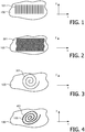
Figure 3 shows asubstrate layer structure 100 where the patterned structure consists of asingle slit 301 having spiral shape. Such a spiral cut causes high flexibility in both x-y-directions, especially the inner tip of the spiral. Additionally, such a spiral shaped structure provides significant stretchability in the z-direction (out-of-plane direction), e.g. in order to fit onto an elliptical or a conical object. -
Figure 4 shows a dual-spiral or "nested" slits 401 that are placed onto thesubstrate layer structure 100 and thus form atop layer 401. The use of such dual-spiral slit allows as an example an easy implementation of two layer sensor structures that are extremely flexible and self-aligned. Such a structure can be very useful in creating multi-layer structures, e.g. so-called zero heat flux type (or related) sensors (seeFig. 8 ) that consist of two or more temperature sensitive elements (thermistors, thermocouples, etc.) separated by a layer of thermal insulation, where the core body temperature is estimated by combining the multiplicity of the temperature readings. In particular, the difference between the temperatures on the opposite sides of the insulation layer (that is proportional to the heat flux from the measured body and the ambient) is being used in the estimation. In some embodiments the heat flux from the body to the ambient can be optionally modulated by the use of heating elements, evaporators, layers of variable effective thermal conductance and alike in order to increase the estimation accuracy. Thus, the use of "nested" slits allows low-cost manufacturing of multi-layer structures from a single substrate sheet and additionally simplifies the problem of aligning the different layers. -
Figures 5-7 show three embodiments of slits forming cam-likes structures. InFig. 5 thestructures substrate layer structure 100 and thus allow two-layer sensor structures that are flexible and stretchable in x-y-directions, i.e. the electronic device(s) can be placed into eachrespective structure -
Figure 6 shows a "nested" cam-like structure where the structures are put on that top of thesubstrate layer structure 100.Figure 6 shows a combination of cam-like and S-shape slits -
Figure 8 shows one example of a flexible and stretchable sensor assembly that forms a temperature sensor. Thesubstrate layer 100 is a "nested" spiral having attached thereto a number of temperature sensors (thermistors) 802. The other part of the spiral also containsthermistors 804 that is located between theinsulation layer electronics 803. - It should be noted that any medical sensor containing electronic components would significantly benefit from using the slits as suggested for improving anatomical fit.
- Certain specific details of the disclosed embodiment are set forth for purposes of explanation rather than limitation, so as to provide a clear and thorough understanding of the present invention.
- Reference signs are included in the claims, however the inclusion of the reference signs is only for clarity reasons and should not be construed as limiting the scope of the claims.
Claims (6)
- A sensor assembly comprising:a flexible and stretchable substrate multi-layer structure (100), wherein the surface of each layer of the flexible and stretchable substrate multi-layer structure (100) is a patterned structure of pre-fixed geometry formed by one or more slits (101-701, 502-702), wherein the patterned structure comprises a nested spiral such that the substrate multi-layer structure (100) becomes adapted to the geometry of a body surface under it, wherein the substrate multi-layer structure has attached thereto a number of temperature sensors, and wherein the layers of the multi-layer structure are separated by a first thermally insulating, stretchable and flexible layer (801a), and one of said layers is mounted on a second thermally insulating, stretchable and flexible layer (801b).
- A sensor assembly according to claim 1, wherein the substrate layer structure (100) is made of an industry-standard printed circuit (PCB) board material.
- A sensor assembly according to claim 2 , wherein the multi-layer substrate layer structure (100) is formed by two or more of the patterned structures.
- A sensor assembly according to claim 1, wherein the one or more slits extend only partially into each layer of the substrate multi-layer structure and wherein the depth of the one or more slits for each layer of the multi-layer structure is varied to further control the stretchability of the substrate multi-layer structure (100).
- A sensor assembly according to claim 1, wherein the patterned structure further comprises:- one or more substantially parallel straight lined slits (101), or- one or more substantially parallel S-shaped slits (201), or- a slit forming a cam-like structure (501-502, 601-602), or- a combination of a at least one S-shaped slit and at least one slit forming cam-like structure (701-702), or- a combination of two or more of the above.
- A sensor assembly as claimed in claim 1, wherein the substrate layer structure (100) is a two layer structure, each layer comprising the nested spiral and a number of temperature sensors (802, 804).
Priority Applications (1)
| Application Number | Priority Date | Filing Date | Title |
|---|---|---|---|
| EP09750237.1A EP2280638B1 (en) | 2008-05-23 | 2009-05-18 | A substrate layer adapted to carry sensors, actuators or electrical components |
Applications Claiming Priority (3)
| Application Number | Priority Date | Filing Date | Title |
|---|---|---|---|
| EP08156802 | 2008-05-23 | ||
| PCT/IB2009/052044 WO2009141780A1 (en) | 2008-05-23 | 2009-05-18 | A substrate layer adapted to carry sensors, actuators or electrical components |
| EP09750237.1A EP2280638B1 (en) | 2008-05-23 | 2009-05-18 | A substrate layer adapted to carry sensors, actuators or electrical components |
Publications (2)
| Publication Number | Publication Date |
|---|---|
| EP2280638A1 EP2280638A1 (en) | 2011-02-09 |
| EP2280638B1 true EP2280638B1 (en) | 2016-12-21 |
Family
ID=40912064
Family Applications (1)
| Application Number | Title | Priority Date | Filing Date |
|---|---|---|---|
| EP09750237.1A Active EP2280638B1 (en) | 2008-05-23 | 2009-05-18 | A substrate layer adapted to carry sensors, actuators or electrical components |
Country Status (7)
| Country | Link |
|---|---|
| US (1) | US9587991B2 (en) |
| EP (1) | EP2280638B1 (en) |
| JP (2) | JP2011523863A (en) |
| CN (1) | CN102036600B (en) |
| BR (1) | BRPI0908620A2 (en) |
| RU (1) | RU2506890C2 (en) |
| WO (1) | WO2009141780A1 (en) |
Families Citing this family (41)
| Publication number | Priority date | Publication date | Assignee | Title |
|---|---|---|---|---|
| WO2009089390A2 (en) | 2008-01-08 | 2009-07-16 | Bluesky Medical Group Inc. | Sustained variable negative pressure wound treatment and method of controlling same |
| US8945030B2 (en) | 2008-03-12 | 2015-02-03 | Bluesky Medical Group, Inc. | Negative pressure dressing and method of using same |
| EP2419006B1 (en) * | 2009-04-15 | 2015-09-30 | 3M Innovative Properties Company | Deep tissue temperature probe constructions |
| EP2419004B1 (en) | 2009-04-15 | 2017-07-19 | 3M Innovative Properties Company | Deep tissue temperature probe constructions |
| US8226294B2 (en) | 2009-08-31 | 2012-07-24 | Arizant Healthcare Inc. | Flexible deep tissue temperature measurement devices |
| CN102687154B (en) | 2009-12-28 | 2016-12-07 | 皇家飞利浦电子股份有限公司 | A kind of system of the beginning of the exacerbation of symptoms for predicting patient |
| CN102687155A (en) | 2009-12-28 | 2012-09-19 | 皇家飞利浦电子股份有限公司 | Biofeedback for program guidance in pulmonary rehabilitation |
| US8292502B2 (en) | 2010-04-07 | 2012-10-23 | Arizant Healthcare Inc. | Constructions for zero-heat-flux, deep tissue temperature measurement devices |
| US8292495B2 (en) | 2010-04-07 | 2012-10-23 | Arizant Healthcare Inc. | Zero-heat-flux, deep tissue temperature measurement devices with thermal sensor calibration |
| US9354122B2 (en) | 2011-05-10 | 2016-05-31 | 3M Innovative Properties Company | Zero-heat-flux, deep tissue temperature measurement system |
| US9869594B2 (en) * | 2012-11-05 | 2018-01-16 | Steamist, Inc. | Controller for steam bath having multiple temperature sensors |
| CN105359148A (en) * | 2013-01-08 | 2016-02-24 | Mc10股份有限公司 | Application for monitoring a property of a surface |
| GB201317746D0 (en) | 2013-10-08 | 2013-11-20 | Smith & Nephew | PH indicator |
| FR3005562A1 (en) * | 2013-05-15 | 2014-11-21 | Ophtimalia | FLEXIBLE PASSIVE SENSOR FOR CONTACT LENS |
| US10736551B2 (en) * | 2014-08-11 | 2020-08-11 | The Board Of Trustees Of The University Of Illinois | Epidermal photonic systems and methods |
| JP6759526B2 (en) | 2015-02-27 | 2020-09-23 | セイコーエプソン株式会社 | Heat flow meter and electronic equipment |
| TWI634702B (en) * | 2016-05-11 | 2018-09-01 | 財團法人工業技術研究院 | Structure constructed by sheet |
| JP2019527566A (en) | 2016-05-13 | 2019-10-03 | スミス アンド ネフュー ピーエルシーSmith & Nephew Public Limited Company | Wound monitoring and treatment device using sensor |
| US10444912B2 (en) | 2016-12-30 | 2019-10-15 | Industrial Technology Research Institute | Sensing method of sensing device and stretchable sensor device |
| WO2018162732A1 (en) | 2017-03-09 | 2018-09-13 | Smith & Nephew Plc | Apparatus and method for imaging blood in a target region of tissue |
| EP3592212A1 (en) | 2017-03-09 | 2020-01-15 | Smith & Nephew PLC | Wound dressing, patch member and method of sensing one or more wound parameters |
| CN110402100A (en) | 2017-03-14 | 2019-11-01 | M·哈伯 | Mthods, systems and devices for non-invasive core body temperature monitoring |
| SG11201909449TA (en) | 2017-04-11 | 2019-11-28 | Smith & Nephew | Component positioning and stress relief for sensor enabled wound dressings |
| CA3062989A1 (en) | 2017-05-15 | 2018-11-22 | Smith & Nephew Plc | Wound analysis device and method |
| US11633153B2 (en) | 2017-06-23 | 2023-04-25 | Smith & Nephew Plc | Positioning of sensors for sensor enabled wound monitoring or therapy |
| GB201809007D0 (en) | 2018-06-01 | 2018-07-18 | Smith & Nephew | Restriction of sensor-monitored region for sensor-enabled wound dressings |
| GB201804502D0 (en) | 2018-03-21 | 2018-05-02 | Smith & Nephew | Biocompatible encapsulation and component stress relief for sensor enabled negative pressure wound therapy dressings |
| JP2020529273A (en) | 2017-08-10 | 2020-10-08 | スミス アンド ネフュー ピーエルシーSmith & Nephew Public Limited Company | Sensor-enabled placement of sensors for wound monitoring or treatment |
| GB201718870D0 (en) | 2017-11-15 | 2017-12-27 | Smith & Nephew Inc | Sensor enabled wound therapy dressings and systems |
| GB201804971D0 (en) | 2018-03-28 | 2018-05-09 | Smith & Nephew | Electrostatic discharge protection for sensors in wound therapy |
| WO2019048624A1 (en) | 2017-09-10 | 2019-03-14 | Smith & Nephew Plc | Systems and methods for inspection of encapsulation and components in sensor equipped wound dressings |
| GB201718859D0 (en) | 2017-11-15 | 2017-12-27 | Smith & Nephew | Sensor positioning for sensor enabled wound therapy dressings and systems |
| US11596553B2 (en) | 2017-09-27 | 2023-03-07 | Smith & Nephew Plc | Ph sensing for sensor enabled negative pressure wound monitoring and therapy apparatuses |
| WO2019072531A1 (en) | 2017-09-28 | 2019-04-18 | Smith & Nephew Plc | Neurostimulation and monitoring using sensor enabled wound monitoring and therapy apparatus |
| WO2019096828A1 (en) | 2017-11-15 | 2019-05-23 | Smith & Nephew Plc | Integrated sensor enabled wound monitoring and/or therapy dressings and systems |
| WO2020053290A1 (en) | 2018-09-12 | 2020-03-19 | Smith & Nephew Plc | Device, apparatus and method of determining skin perfusion pressure |
| JP2021111848A (en) * | 2020-01-08 | 2021-08-02 | 株式会社Jvcケンウッド | Video playback device, record playback device, video playback method, and video playback program |
| CN111904395B (en) * | 2020-07-24 | 2022-04-01 | 厦门大学 | Flexible base material for physiological information sensing and manufacturing method thereof |
| US20220031241A1 (en) * | 2020-07-28 | 2022-02-03 | Xsensor Technology Corporation | Foot sensor and other sensor pads |
| US11534086B2 (en) | 2020-10-30 | 2022-12-27 | Medtronic Minimed, Inc. | Low-profile wearable medical device |
| CN114136203B (en) * | 2021-11-12 | 2023-04-07 | 中国科学院金属研究所 | Preparation method of flexible strain sensor with high sensitivity and good cycling stability |
Citations (1)
| Publication number | Priority date | Publication date | Assignee | Title |
|---|---|---|---|---|
| US20070206655A1 (en) * | 2006-03-03 | 2007-09-06 | Haslett James W | Bandage with sensors |
Family Cites Families (41)
| Publication number | Priority date | Publication date | Assignee | Title |
|---|---|---|---|---|
| JPS58172809A (en) * | 1982-04-02 | 1983-10-11 | 株式会社日立製作所 | Wiring structure using flexible circuit board |
| JPH033283Y2 (en) * | 1984-12-27 | 1991-01-29 | ||
| JPS6220393A (en) | 1985-07-18 | 1987-01-28 | 松下電工株式会社 | Printed wiring board |
| DE3633803C2 (en) * | 1985-10-22 | 1995-10-19 | Telectronics Nv | Defibrillator electrode |
| JPH0311786A (en) * | 1989-06-09 | 1991-01-21 | Ibiden Co Ltd | Printed wiring board |
| JP2989410B2 (en) | 1993-02-25 | 1999-12-13 | シャープ株式会社 | Flexible film substrate |
| US5746207A (en) * | 1993-03-23 | 1998-05-05 | Mclaughlin; James Andrew | Profiled biosignal electrode device |
| RU2138192C1 (en) * | 1995-03-06 | 1999-09-27 | Полартекникс, Лтд. | Method of identification of tissue type and apparatus for method embodiment |
| JPH09201338A (en) * | 1996-01-26 | 1997-08-05 | Hiromichi Omura | Flexible living body information signal generating device |
| JPH11219623A (en) | 1998-02-03 | 1999-08-10 | Japan Aviation Electronics Ind Ltd | Flexible wiring member having high degree of freedom for wiring arrangement |
| US6385473B1 (en) * | 1999-04-15 | 2002-05-07 | Nexan Limited | Physiological sensor device |
| DE29907768U1 (en) | 1999-05-03 | 1999-11-25 | Paul Ruester & Co U No | Flexible surface temperature sensor |
| US6512512B1 (en) | 1999-07-31 | 2003-01-28 | Litton Systems, Inc. | Touch panel with improved optical performance |
| US6454725B1 (en) | 2000-05-12 | 2002-09-24 | Chu Yih Yu | Thermometer for body temperature detection |
| US7181261B2 (en) | 2000-05-15 | 2007-02-20 | Silver James H | Implantable, retrievable, thrombus minimizing sensors |
| US20040030258A1 (en) | 2000-10-09 | 2004-02-12 | Williams Christopher Edward | Sensor assembly for monitoring an infant brain |
| US6567680B2 (en) * | 2001-02-02 | 2003-05-20 | Medical Data Electronics | Disposable electro-cardiogram transmitter device and electrode node placement facilitator |
| JP4418120B2 (en) * | 2001-03-12 | 2010-02-17 | グローリー株式会社 | Fingerprint sensor, fingerprint collation device, and method of manufacturing fingerprint sensor |
| AU2002255953A1 (en) * | 2001-03-27 | 2002-10-08 | Aron Z. Kain | Wireless system for measuring distension in flexible tubes |
| US6847913B2 (en) | 2001-10-04 | 2005-01-25 | The Johns Hopkins University | Ambulatory surface skin temperature monitor |
| JP4157914B2 (en) * | 2002-03-20 | 2008-10-01 | 坂野 數仁 | Temperature measuring apparatus and temperature measuring method |
| US20050226310A1 (en) | 2002-03-20 | 2005-10-13 | Sanyo Electric Co., Ltd. | Adhesive clinical thermometer pad and temperature measuring pad |
| JP2004024551A (en) * | 2002-06-26 | 2004-01-29 | Renesas Technology Corp | Semiconductor device for sensor system |
| DE10312158A1 (en) | 2003-03-19 | 2004-10-14 | Hirschmann Electronics Gmbh & Co. Kg | Curved circuit board of an antenna amplifier for a vehicle antenna device |
| WO2004092581A1 (en) * | 2003-04-15 | 2004-10-28 | Board Of Trustees Operating Michigan State University | Prestrained thin-film shape memory actuator using polymeric substrates |
| FR2858758B1 (en) | 2003-08-14 | 2006-04-07 | Tam Telesante Sarl | MEDICAL MONITORING SYSTEM USING A CLOTHING |
| KR20060101755A (en) * | 2003-08-26 | 2006-09-26 | 코닌클리즈케 필립스 일렉트로닉스 엔.브이. | Printed circuit board with integrated inductor |
| JP2005137456A (en) * | 2003-11-04 | 2005-06-02 | Nitto Denko Corp | Electrode device to be mounted on body |
| US6964205B2 (en) * | 2003-12-30 | 2005-11-15 | Tekscan Incorporated | Sensor with plurality of sensor elements arranged with respect to a substrate |
| JP4463653B2 (en) * | 2004-05-10 | 2010-05-19 | 株式会社フジクラ | Hybrid sensor |
| EP1763860A4 (en) * | 2004-09-03 | 2012-11-07 | Semiconductor Energy Lab | Health data collecting system and semiconductor device |
| JP2006108431A (en) * | 2004-10-06 | 2006-04-20 | Sharp Corp | Semiconductor device |
| JP2007053248A (en) * | 2005-08-18 | 2007-03-01 | Tdk Corp | Flexible substrate, mounting structure, display unit and portable electronic device |
| JP4308179B2 (en) * | 2005-09-12 | 2009-08-05 | レノボ・シンガポール・プライベート・リミテッド | Keyboard wiring structure and computer |
| US8032210B2 (en) * | 2005-10-06 | 2011-10-04 | Spinematrix, Inc. | EMG diagnostic system and method |
| JP2007209428A (en) * | 2006-02-08 | 2007-08-23 | Matsushita Electric Ind Co Ltd | Instrument and system for measuring biological information |
| US7712373B2 (en) * | 2006-03-03 | 2010-05-11 | Nagle H Troy | Sensor device for real-time monitoring or relative movement using capacitive fabric sensors |
| JP4143653B2 (en) * | 2006-05-24 | 2008-09-03 | オムロン株式会社 | Array type capacitive sensor |
| JP4805773B2 (en) * | 2006-09-20 | 2011-11-02 | シチズンホールディングス株式会社 | Electronic thermometer |
| US8238996B2 (en) | 2006-12-05 | 2012-08-07 | Tyco Healthcare Group Lp | Electrode array |
| JP5295584B2 (en) * | 2008-02-14 | 2013-09-18 | 国立大学法人 筑波大学 | Blood flow measuring device and brain activity measuring device using blood flow measuring device |
-
2009
- 2009-05-18 CN CN200980118549.8A patent/CN102036600B/en active Active
- 2009-05-18 WO PCT/IB2009/052044 patent/WO2009141780A1/en active Application Filing
- 2009-05-18 BR BRPI0908620A patent/BRPI0908620A2/en not_active Application Discontinuation
- 2009-05-18 RU RU2010152667/14A patent/RU2506890C2/en active
- 2009-05-18 JP JP2011510078A patent/JP2011523863A/en active Pending
- 2009-05-18 EP EP09750237.1A patent/EP2280638B1/en active Active
- 2009-05-18 US US12/992,321 patent/US9587991B2/en active Active
-
2014
- 2014-09-26 JP JP2014196356A patent/JP5913509B2/en active Active
Patent Citations (1)
| Publication number | Priority date | Publication date | Assignee | Title |
|---|---|---|---|---|
| US20070206655A1 (en) * | 2006-03-03 | 2007-09-06 | Haslett James W | Bandage with sensors |
Also Published As
| Publication number | Publication date |
|---|---|
| WO2009141780A1 (en) | 2009-11-26 |
| RU2010152667A (en) | 2012-06-27 |
| EP2280638A1 (en) | 2011-02-09 |
| BRPI0908620A2 (en) | 2016-06-14 |
| JP2015052598A (en) | 2015-03-19 |
| RU2506890C2 (en) | 2014-02-20 |
| CN102036600B (en) | 2014-08-06 |
| US20110069459A1 (en) | 2011-03-24 |
| JP5913509B2 (en) | 2016-04-27 |
| CN102036600A (en) | 2011-04-27 |
| JP2011523863A (en) | 2011-08-25 |
| US9587991B2 (en) | 2017-03-07 |
Similar Documents
| Publication | Publication Date | Title |
|---|---|---|
| EP2280638B1 (en) | A substrate layer adapted to carry sensors, actuators or electrical components | |
| WO2009141777A1 (en) | A substrate layer adapted to carry sensors, actuators or electrical components | |
| JP7285859B2 (en) | wearable device | |
| US10653332B2 (en) | Conductive stiffener, method of making a conductive stiffener, and conductive adhesive and encapsulation layers | |
| JP7154508B2 (en) | Wiring board and method for manufacturing wiring board | |
| US11330984B2 (en) | Wearable graphene sensors | |
| Kwak et al. | Skin‐integrated devices with soft, holey architectures for wireless physiological monitoring, with applications in the neonatal intensive care unit | |
| JP6812033B2 (en) | Electrode belt device for measuring biological signals | |
| JP2020010052A5 (en) | ||
| CN111225707B (en) | High volume manufacturing of catheters comprising electrodes with low impedance at low frequencies | |
| US11910531B2 (en) | Flexible printed circuit board having a battery mounted thereto | |
| JP2018105775A (en) | Flexible device | |
| Chuo et al. | Sensor layer of a multiparameter single-point integrated system | |
| WO2021241308A1 (en) | Wearable device and detection method | |
| JP7383928B2 (en) | stretchable device | |
| CN116600701A (en) | Flexible circuit board for continuous analyte monitoring device | |
| WO2023043866A1 (en) | Apparatus and method for measuring physiological parameters of mammal subject using easily removable flexible electronics and applications thereof | |
| CN114599148A (en) | Inorganic flexible electronic device based on grid substrate and integration method thereof | |
| WO2017117771A1 (en) | Physiological index detection apparatus and system | |
| Neuman | Thin-film microelectronic wearable body sensors |
Legal Events
| Date | Code | Title | Description |
|---|---|---|---|
| PUAI | Public reference made under article 153(3) epc to a published international application that has entered the european phase |
Free format text: ORIGINAL CODE: 0009012 |
|
| 17P | Request for examination filed |
Effective date: 20101223 |
|
| AK | Designated contracting states |
Kind code of ref document: A1 Designated state(s): AT BE BG CH CY CZ DE DK EE ES FI FR GB GR HR HU IE IS IT LI LT LU LV MC MK MT NL NO PL PT RO SE SI SK TR |
|
| AX | Request for extension of the european patent |
Extension state: AL BA RS |
|
| DAX | Request for extension of the european patent (deleted) | ||
| 17Q | First examination report despatched |
Effective date: 20121130 |
|
| RAP1 | Party data changed (applicant data changed or rights of an application transferred) |
Owner name: KONINKLIJKE PHILIPS N.V. |
|
| REG | Reference to a national code |
Ref country code: DE Ref legal event code: R079 Ref document number: 602009043235 Country of ref document: DE Free format text: PREVIOUS MAIN CLASS: A61B0005000000 Ipc: A61B0005040000 |
|
| RIC1 | Information provided on ipc code assigned before grant |
Ipc: G01K 13/00 20060101ALI20160520BHEP Ipc: A61B 5/00 20060101ALI20160520BHEP Ipc: G01K 1/16 20060101ALI20160520BHEP Ipc: A61B 5/01 20060101ALI20160520BHEP Ipc: A61B 5/04 20060101AFI20160520BHEP |
|
| GRAP | Despatch of communication of intention to grant a patent |
Free format text: ORIGINAL CODE: EPIDOSNIGR1 |
|
| INTG | Intention to grant announced |
Effective date: 20160713 |
|
| GRAS | Grant fee paid |
Free format text: ORIGINAL CODE: EPIDOSNIGR3 |
|
| GRAA | (expected) grant |
Free format text: ORIGINAL CODE: 0009210 |
|
| AK | Designated contracting states |
Kind code of ref document: B1 Designated state(s): AT BE BG CH CY CZ DE DK EE ES FI FR GB GR HR HU IE IS IT LI LT LU LV MC MK MT NL NO PL PT RO SE SI SK TR |
|
| REG | Reference to a national code |
Ref country code: GB Ref legal event code: FG4D |
|
| REG | Reference to a national code |
Ref country code: CH Ref legal event code: EP |
|
| REG | Reference to a national code |
Ref country code: IE Ref legal event code: FG4D |
|
| REG | Reference to a national code |
Ref country code: AT Ref legal event code: REF Ref document number: 854741 Country of ref document: AT Kind code of ref document: T Effective date: 20170115 |
|
| REG | Reference to a national code |
Ref country code: DE Ref legal event code: R096 Ref document number: 602009043235 Country of ref document: DE |
|
| PG25 | Lapsed in a contracting state [announced via postgrant information from national office to epo] |
Ref country code: LV Free format text: LAPSE BECAUSE OF FAILURE TO SUBMIT A TRANSLATION OF THE DESCRIPTION OR TO PAY THE FEE WITHIN THE PRESCRIBED TIME-LIMIT Effective date: 20161221 |
|
| REG | Reference to a national code |
Ref country code: LT Ref legal event code: MG4D |
|
| REG | Reference to a national code |
Ref country code: NL Ref legal event code: MP Effective date: 20161221 |
|
| PG25 | Lapsed in a contracting state [announced via postgrant information from national office to epo] |
Ref country code: NO Free format text: LAPSE BECAUSE OF FAILURE TO SUBMIT A TRANSLATION OF THE DESCRIPTION OR TO PAY THE FEE WITHIN THE PRESCRIBED TIME-LIMIT Effective date: 20170321 Ref country code: GR Free format text: LAPSE BECAUSE OF FAILURE TO SUBMIT A TRANSLATION OF THE DESCRIPTION OR TO PAY THE FEE WITHIN THE PRESCRIBED TIME-LIMIT Effective date: 20170322 Ref country code: SE Free format text: LAPSE BECAUSE OF FAILURE TO SUBMIT A TRANSLATION OF THE DESCRIPTION OR TO PAY THE FEE WITHIN THE PRESCRIBED TIME-LIMIT Effective date: 20161221 Ref country code: LT Free format text: LAPSE BECAUSE OF FAILURE TO SUBMIT A TRANSLATION OF THE DESCRIPTION OR TO PAY THE FEE WITHIN THE PRESCRIBED TIME-LIMIT Effective date: 20161221 |
|
| REG | Reference to a national code |
Ref country code: AT Ref legal event code: MK05 Ref document number: 854741 Country of ref document: AT Kind code of ref document: T Effective date: 20161221 |
|
| REG | Reference to a national code |
Ref country code: FR Ref legal event code: PLFP Year of fee payment: 9 |
|
| PG25 | Lapsed in a contracting state [announced via postgrant information from national office to epo] |
Ref country code: FI Free format text: LAPSE BECAUSE OF FAILURE TO SUBMIT A TRANSLATION OF THE DESCRIPTION OR TO PAY THE FEE WITHIN THE PRESCRIBED TIME-LIMIT Effective date: 20161221 Ref country code: HR Free format text: LAPSE BECAUSE OF FAILURE TO SUBMIT A TRANSLATION OF THE DESCRIPTION OR TO PAY THE FEE WITHIN THE PRESCRIBED TIME-LIMIT Effective date: 20161221 |
|
| PG25 | Lapsed in a contracting state [announced via postgrant information from national office to epo] |
Ref country code: NL Free format text: LAPSE BECAUSE OF FAILURE TO SUBMIT A TRANSLATION OF THE DESCRIPTION OR TO PAY THE FEE WITHIN THE PRESCRIBED TIME-LIMIT Effective date: 20161221 |
|
| PG25 | Lapsed in a contracting state [announced via postgrant information from national office to epo] |
Ref country code: CZ Free format text: LAPSE BECAUSE OF FAILURE TO SUBMIT A TRANSLATION OF THE DESCRIPTION OR TO PAY THE FEE WITHIN THE PRESCRIBED TIME-LIMIT Effective date: 20161221 Ref country code: IS Free format text: LAPSE BECAUSE OF FAILURE TO SUBMIT A TRANSLATION OF THE DESCRIPTION OR TO PAY THE FEE WITHIN THE PRESCRIBED TIME-LIMIT Effective date: 20170421 Ref country code: SK Free format text: LAPSE BECAUSE OF FAILURE TO SUBMIT A TRANSLATION OF THE DESCRIPTION OR TO PAY THE FEE WITHIN THE PRESCRIBED TIME-LIMIT Effective date: 20161221 Ref country code: RO Free format text: LAPSE BECAUSE OF FAILURE TO SUBMIT A TRANSLATION OF THE DESCRIPTION OR TO PAY THE FEE WITHIN THE PRESCRIBED TIME-LIMIT Effective date: 20161221 Ref country code: EE Free format text: LAPSE BECAUSE OF FAILURE TO SUBMIT A TRANSLATION OF THE DESCRIPTION OR TO PAY THE FEE WITHIN THE PRESCRIBED TIME-LIMIT Effective date: 20161221 |
|
| PG25 | Lapsed in a contracting state [announced via postgrant information from national office to epo] |
Ref country code: PT Free format text: LAPSE BECAUSE OF FAILURE TO SUBMIT A TRANSLATION OF THE DESCRIPTION OR TO PAY THE FEE WITHIN THE PRESCRIBED TIME-LIMIT Effective date: 20170421 Ref country code: IT Free format text: LAPSE BECAUSE OF FAILURE TO SUBMIT A TRANSLATION OF THE DESCRIPTION OR TO PAY THE FEE WITHIN THE PRESCRIBED TIME-LIMIT Effective date: 20161221 Ref country code: ES Free format text: LAPSE BECAUSE OF FAILURE TO SUBMIT A TRANSLATION OF THE DESCRIPTION OR TO PAY THE FEE WITHIN THE PRESCRIBED TIME-LIMIT Effective date: 20161221 Ref country code: BG Free format text: LAPSE BECAUSE OF FAILURE TO SUBMIT A TRANSLATION OF THE DESCRIPTION OR TO PAY THE FEE WITHIN THE PRESCRIBED TIME-LIMIT Effective date: 20170321 Ref country code: LU Free format text: LAPSE BECAUSE OF NON-PAYMENT OF DUE FEES Effective date: 20170531 Ref country code: AT Free format text: LAPSE BECAUSE OF FAILURE TO SUBMIT A TRANSLATION OF THE DESCRIPTION OR TO PAY THE FEE WITHIN THE PRESCRIBED TIME-LIMIT Effective date: 20161221 Ref country code: PL Free format text: LAPSE BECAUSE OF FAILURE TO SUBMIT A TRANSLATION OF THE DESCRIPTION OR TO PAY THE FEE WITHIN THE PRESCRIBED TIME-LIMIT Effective date: 20161221 Ref country code: BE Free format text: LAPSE BECAUSE OF FAILURE TO SUBMIT A TRANSLATION OF THE DESCRIPTION OR TO PAY THE FEE WITHIN THE PRESCRIBED TIME-LIMIT Effective date: 20161221 |
|
| REG | Reference to a national code |
Ref country code: DE Ref legal event code: R097 Ref document number: 602009043235 Country of ref document: DE |
|
| PLBE | No opposition filed within time limit |
Free format text: ORIGINAL CODE: 0009261 |
|
| STAA | Information on the status of an ep patent application or granted ep patent |
Free format text: STATUS: NO OPPOSITION FILED WITHIN TIME LIMIT |
|
| 26N | No opposition filed |
Effective date: 20170922 |
|
| PG25 | Lapsed in a contracting state [announced via postgrant information from national office to epo] |
Ref country code: DK Free format text: LAPSE BECAUSE OF FAILURE TO SUBMIT A TRANSLATION OF THE DESCRIPTION OR TO PAY THE FEE WITHIN THE PRESCRIBED TIME-LIMIT Effective date: 20161221 |
|
| REG | Reference to a national code |
Ref country code: CH Ref legal event code: PL |
|
| PG25 | Lapsed in a contracting state [announced via postgrant information from national office to epo] |
Ref country code: MC Free format text: LAPSE BECAUSE OF FAILURE TO SUBMIT A TRANSLATION OF THE DESCRIPTION OR TO PAY THE FEE WITHIN THE PRESCRIBED TIME-LIMIT Effective date: 20161221 |
|
| REG | Reference to a national code |
Ref country code: IE Ref legal event code: MM4A |
|
| PG25 | Lapsed in a contracting state [announced via postgrant information from national office to epo] |
Ref country code: SI Free format text: LAPSE BECAUSE OF FAILURE TO SUBMIT A TRANSLATION OF THE DESCRIPTION OR TO PAY THE FEE WITHIN THE PRESCRIBED TIME-LIMIT Effective date: 20161221 Ref country code: LI Free format text: LAPSE BECAUSE OF NON-PAYMENT OF DUE FEES Effective date: 20170531 Ref country code: CH Free format text: LAPSE BECAUSE OF NON-PAYMENT OF DUE FEES Effective date: 20170531 |
|
| PG25 | Lapsed in a contracting state [announced via postgrant information from national office to epo] |
Ref country code: LU Free format text: LAPSE BECAUSE OF NON-PAYMENT OF DUE FEES Effective date: 20170518 |
|
| PG25 | Lapsed in a contracting state [announced via postgrant information from national office to epo] |
Ref country code: IE Free format text: LAPSE BECAUSE OF NON-PAYMENT OF DUE FEES Effective date: 20170518 |
|
| REG | Reference to a national code |
Ref country code: FR Ref legal event code: PLFP Year of fee payment: 10 |
|
| PG25 | Lapsed in a contracting state [announced via postgrant information from national office to epo] |
Ref country code: MT Free format text: LAPSE BECAUSE OF NON-PAYMENT OF DUE FEES Effective date: 20170518 |
|
| PG25 | Lapsed in a contracting state [announced via postgrant information from national office to epo] |
Ref country code: HU Free format text: LAPSE BECAUSE OF FAILURE TO SUBMIT A TRANSLATION OF THE DESCRIPTION OR TO PAY THE FEE WITHIN THE PRESCRIBED TIME-LIMIT; INVALID AB INITIO Effective date: 20090518 |
|
| PG25 | Lapsed in a contracting state [announced via postgrant information from national office to epo] |
Ref country code: CY Free format text: LAPSE BECAUSE OF NON-PAYMENT OF DUE FEES Effective date: 20161221 |
|
| PG25 | Lapsed in a contracting state [announced via postgrant information from national office to epo] |
Ref country code: MK Free format text: LAPSE BECAUSE OF FAILURE TO SUBMIT A TRANSLATION OF THE DESCRIPTION OR TO PAY THE FEE WITHIN THE PRESCRIBED TIME-LIMIT Effective date: 20161221 |
|
| PG25 | Lapsed in a contracting state [announced via postgrant information from national office to epo] |
Ref country code: TR Free format text: LAPSE BECAUSE OF FAILURE TO SUBMIT A TRANSLATION OF THE DESCRIPTION OR TO PAY THE FEE WITHIN THE PRESCRIBED TIME-LIMIT Effective date: 20161221 |
|
| REG | Reference to a national code |
Ref country code: DE Ref legal event code: R079 Ref document number: 602009043235 Country of ref document: DE Free format text: PREVIOUS MAIN CLASS: A61B0005040000 Ipc: A61B0005240000 |
|
| PGFP | Annual fee paid to national office [announced via postgrant information from national office to epo] |
Ref country code: FR Payment date: 20230523 Year of fee payment: 15 Ref country code: DE Payment date: 20220628 Year of fee payment: 15 |
|
| PGFP | Annual fee paid to national office [announced via postgrant information from national office to epo] |
Ref country code: GB Payment date: 20230523 Year of fee payment: 15 |