EP2280486A1 - Analog-Digital-Wandler mit sich überlappend geführter binärer Suche - Google Patents
Analog-Digital-Wandler mit sich überlappend geführter binärer Suche Download PDFInfo
- Publication number
- EP2280486A1 EP2280486A1 EP10151660A EP10151660A EP2280486A1 EP 2280486 A1 EP2280486 A1 EP 2280486A1 EP 10151660 A EP10151660 A EP 10151660A EP 10151660 A EP10151660 A EP 10151660A EP 2280486 A1 EP2280486 A1 EP 2280486A1
- Authority
- EP
- European Patent Office
- Prior art keywords
- hierarchical
- comparing means
- input signal
- analog
- amplifying circuit
- Prior art date
- Legal status (The legal status is an assumption and is not a legal conclusion. Google has not performed a legal analysis and makes no representation as to the accuracy of the status listed.)
- Withdrawn
Links
Images


Classifications
-
- H—ELECTRICITY
- H03—ELECTRONIC CIRCUITRY
- H03M—CODING; DECODING; CODE CONVERSION IN GENERAL
- H03M1/00—Analogue/digital conversion; Digital/analogue conversion
- H03M1/10—Calibration or testing
-
- H—ELECTRICITY
- H03—ELECTRONIC CIRCUITRY
- H03M—CODING; DECODING; CODE CONVERSION IN GENERAL
- H03M1/00—Analogue/digital conversion; Digital/analogue conversion
- H03M1/002—Provisions or arrangements for saving power, e.g. by allowing a sleep mode, using lower supply voltage for downstream stages, using multiple clock domains or by selectively turning on stages when needed
-
- H—ELECTRICITY
- H03—ELECTRONIC CIRCUITRY
- H03M—CODING; DECODING; CODE CONVERSION IN GENERAL
- H03M1/00—Analogue/digital conversion; Digital/analogue conversion
- H03M1/10—Calibration or testing
- H03M1/1009—Calibration
- H03M1/1014—Calibration at one point of the transfer characteristic, i.e. by adjusting a single reference value, e.g. bias or gain error
- H03M1/1023—Offset correction
-
- H—ELECTRICITY
- H03—ELECTRONIC CIRCUITRY
- H03M—CODING; DECODING; CODE CONVERSION IN GENERAL
- H03M1/00—Analogue/digital conversion; Digital/analogue conversion
- H03M1/12—Analogue/digital converters
- H03M1/14—Conversion in steps with each step involving the same or a different conversion means and delivering more than one bit
- H03M1/16—Conversion in steps with each step involving the same or a different conversion means and delivering more than one bit with scale factor modification, i.e. by changing the amplification between the steps
-
- H—ELECTRICITY
- H03—ELECTRONIC CIRCUITRY
- H03M—CODING; DECODING; CODE CONVERSION IN GENERAL
- H03M1/00—Analogue/digital conversion; Digital/analogue conversion
- H03M1/12—Analogue/digital converters
- H03M1/34—Analogue value compared with reference values
- H03M1/36—Analogue value compared with reference values simultaneously only, i.e. parallel type
-
- H—ELECTRICITY
- H03—ELECTRONIC CIRCUITRY
- H03M—CODING; DECODING; CODE CONVERSION IN GENERAL
- H03M1/00—Analogue/digital conversion; Digital/analogue conversion
- H03M1/12—Analogue/digital converters
- H03M1/34—Analogue value compared with reference values
- H03M1/38—Analogue value compared with reference values sequentially only, e.g. successive approximation type
- H03M1/44—Sequential comparisons in series-connected stages with change in value of analogue signal
-
- H—ELECTRICITY
- H03—ELECTRONIC CIRCUITRY
- H03M—CODING; DECODING; CODE CONVERSION IN GENERAL
- H03M1/00—Analogue/digital conversion; Digital/analogue conversion
- H03M1/12—Analogue/digital converters
- H03M1/1205—Multiplexed conversion systems
- H03M1/121—Interleaved, i.e. using multiple converters or converter parts for one channel
- H03M1/1215—Interleaved, i.e. using multiple converters or converter parts for one channel using time-division multiplexing
-
- H—ELECTRICITY
- H03—ELECTRONIC CIRCUITRY
- H03M—CODING; DECODING; CODE CONVERSION IN GENERAL
- H03M1/00—Analogue/digital conversion; Digital/analogue conversion
- H03M1/12—Analogue/digital converters
- H03M1/1235—Non-linear conversion not otherwise provided for in subgroups of H03M1/12
-
- H—ELECTRICITY
- H03—ELECTRONIC CIRCUITRY
- H03M—CODING; DECODING; CODE CONVERSION IN GENERAL
- H03M1/00—Analogue/digital conversion; Digital/analogue conversion
- H03M1/12—Analogue/digital converters
- H03M1/14—Conversion in steps with each step involving the same or a different conversion means and delivering more than one bit
- H03M1/16—Conversion in steps with each step involving the same or a different conversion means and delivering more than one bit with scale factor modification, i.e. by changing the amplification between the steps
- H03M1/164—Conversion in steps with each step involving the same or a different conversion means and delivering more than one bit with scale factor modification, i.e. by changing the amplification between the steps the steps being performed sequentially in series-connected stages
-
- H—ELECTRICITY
- H03—ELECTRONIC CIRCUITRY
- H03M—CODING; DECODING; CODE CONVERSION IN GENERAL
- H03M1/00—Analogue/digital conversion; Digital/analogue conversion
- H03M1/12—Analogue/digital converters
- H03M1/34—Analogue value compared with reference values
- H03M1/36—Analogue value compared with reference values simultaneously only, i.e. parallel type
- H03M1/361—Analogue value compared with reference values simultaneously only, i.e. parallel type having a separate comparator and reference value for each quantisation level, i.e. full flash converter type
-
- H—ELECTRICITY
- H03—ELECTRONIC CIRCUITRY
- H03M—CODING; DECODING; CODE CONVERSION IN GENERAL
- H03M1/00—Analogue/digital conversion; Digital/analogue conversion
- H03M1/12—Analogue/digital converters
- H03M1/34—Analogue value compared with reference values
- H03M1/38—Analogue value compared with reference values sequentially only, e.g. successive approximation type
- H03M1/44—Sequential comparisons in series-connected stages with change in value of analogue signal
- H03M1/445—Sequential comparisons in series-connected stages with change in value of analogue signal the stages being of the folding type
Definitions
- the present invention generally relates to an analog-to-digital converter wherein a binary search is used.
- Some applications such as hard disk read channels or wideband wireless standards, require a low-resolution (for example, approximately 6 bit), high-speed (for example, greater than 1 Giga-samples per second (GS/s)) analog-to-digital converter (ADC).
- a low-resolution for example, approximately 6 bit
- high-speed for example, greater than 1 Giga-samples per second (GS/s)
- ADC analog-to-digital converter
- time-interleaved Successive Approximation Register (SAR) converters and flash converters.
- Single-channel SAR converters typically operate at sampling frequencies of a few hundred megasamples per second (MS/s) (for example, approximately 300 MS/s). As a result, a large number of channels would need to be interleaved, yielding a large input capacitance.
- a time-interleaved SAR architecture for the same specifications could have an input capacitance 10-20 times larger than a pipelined binary search ADC.
- Flash converters on the other hand would be severely limited by quantized power, as for each conversion 63 comparisons (6 bit) would have to be mode at low noise/offset.
- the power requirement for similar specifications with a calibrated flash converter would be 10 times larger than the power consumption in a pipelined binary search ADC.
- Pipelined analog-to-digital converters have become popular for sampling rates from a few megasamples per second up to 100 megasamples per second. Dynamic pipelined conversion enables low power quantization at high speed with low input capacitance but requires calibration.
- US patent application US2005/0062635 introduces a pipelined analog-to-digital converter that follows a non-linear scale and allows operation at frequencies of 2 GHz and more.
- the pipelined ADC comprises a number of comparator stages where the thresholds of the comparator stages are adjusted in accordance with the digital conversion results from the previous stage.
- an architecture and method are proposed in this document to provide a pipelined ADC with a programmable characteristic so even a non-linear scale may be implemented.
- the output signals are processed via linear signal processing, using linear amplifiers.
- the present invention aims to provide for an analog-to-digital converter with reduced power consumption (low-resolution, high-speed).
- a pipelined analog-to-digital converter for converting an analog input signal into a digital signal comprises a plurality of comparing means having tuneable thresholds for comparing an input signal with, whereof at least two of said given thresholds are different, and a plurality of amplifying circuits.
- the plurality of comparing means is configured to form a hierarchical tree structure, having a plurality of hierarchical levels. At least one of the hierarchical levels is associated with at least one amplifying circuit of the plurality of amplifying circuits. The at least one amplifying circuit generates the input of at least one comparing means at the next hierarchical level.
- the plurality of hierarchical levels comprises means for setting the tuneable thresholds in accordance to the output of previous hierarchical level so that non-linear distortion of the preceding hierarchical level is removed.
- the means for setting the tuneable threshold comprises variable capacitors.
- the variable capacitors comprise first variable capacitors associated with the comparing means and second variable capacitors associated with the amplifying circuits.
- the thresholds are tuned to the output of the previous level when a desired input threshold is applied, thereby cancelling non-linear distortion of the preceding hierarchical level.
- the amplifying circuits are non-linear multiplying digital to analog converters (NLMDAC).
- a pipelined ADC wherein each of said plurality of comparing means is implemented with an amplifying circuit of said plurality of amplifying circuits in a comparator/track-and-hold amplifying circuit.
- a comparator/track-and-hold amplifying circuit comprises a dynamic amplifier and a latch.
- Each of the plurality of comparator/track-and-hold amplifying circuits generates an input signal for two comparator/track-and-hold amplifying circuits in the subsequent level.
- the comparator/track-and-hold amplifying circuits have tunable thresholds.
- the comparator/track-and-hold amplifying circuits comprise variable capacitors. By setting the variable capacitors, given thresholds are provided. Preferably the thresholds are tuned to the output of the previous level when a desired input threshold is applied, thereby cancelling non-linear distortion of the preceding comparator/track-and-hold amplifying circuits.
- a method for converting an analog input signal into a digital output using a pipelined analog-to-digital converter according to one of the foregoing embodiments. The method comprises the steps of
- the method implements a binary search algorithm.
- a binary search instead of a parallel one, the number of active comparators is reduced and therefore the power consumption.
- an amplifying circuit in this or the succeeding level either adds or subtracts from the input signal a value depending on the weight of the decision.
- the comparing means of a first, parent hierarchical level controls or triggers the comparing means of a subsequent, child hierarchical level.
- the method for converting an analog input signal into a digital output is preceded by a calibration step.
- the threshold of at least one comparing means is tuned during a calibration period and from that point the comparator has a given threshold.
- the step of comparing yields an output signal that is fed to a amplifying circuit/DAC, implementing a successive approximation process.
- a binary code is determined.
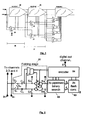
- Fig. 1 illustrates a general block diagram of 3 bits of 1 bit per stage pipelined A/D converter.
- Fig. 2 illustrates an example of a hybrid ADC.
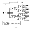
- Fig. 3 illustrates a schematic of a pipelined binary search method.
- Fig. 4 shows a block diagram of 3 bits of 1 bit per stage pipelined ADC converter.
- Fig. 5 shows a schematic of a folding front-end stage.
- Fig. 6 the waveforms of a folding front-end stage.
- Fig. 7 shows the timing of the clock signals of a folding stage.
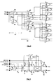
- Fig. 8 shows an example of a possible comparator-T/H circuit.
- Fig. 9 shows a plot of a simulated input-output characteristic of the dynamic amplifier.
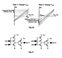
- Fig. 10 shows plots of different calibration steps, for calibrating Ca.
- Fig. 11 shows schematics for circuits used to gate clock for each row.
- Fig. 12 shows the timing of different clock signals in the Comparator /Track&Hold Amplifier tree.
- top, bottom, over, under and the like in the description are used for descriptive purposes and not necessarily for describing relative positions.
- the terms so used are interchangeable under appropriate circumstances and the embodiments of the invention described herein can operate in other orientations than described or illustrated herein.
- ADCs are based on the principle of sequential conversion.
- the analog signal to be converted is first sampled and compared with a threshold in a first stage comparator.
- the signal is then amplified by an amplification factor of 2 and the bit value of the first stage subtracted there from, resulting in a residue signal.
- This residue signal is the input signal for the second stage.
- the residue signal is sampled and compared by a second stage comparator. This process continues in subsequent stages up to the required bit resolution.
- This disclosure provides a pipelined analog-to-digital converter with non-linear signal processing (this is equivalent to residue generation and amplification) where each ADC threshold is implemented with a different calibrated comparator. This calibration can then compensate for nonlinearity as well as random offset due to device mismatch. Furthermore, only the comparators and amplifiers required for a binary search are being activated whereby low power consumption is achieved.
- the pipelined converter further comprises a folding front-end.
- the pipelined converter further comprises an n-bit flash analog-to-digital converter.
- a pipelined analog-to-digital converter for converting an analog input signal into a digital signal is provided as illustrated in Figure 1 .
- the PL ADC comprises a plurality of comparing means (31), (32), (33) having a tuneable threshold for comparing an input signal with whereby at least two of said given thresholds are different.
- the threshold is tuned during a calibration period and from that point each comparator has a given threshold.
- the PL ADC further comprises a plurality of amplifying circuits (34), (35).
- the plurality of comparing means is configured to form a hierarchical tree structure having a plurality of hierarchical levels (36), (37), wherein at least one of said hierarchical levels is associated with at least one amplifying circuit of the plurality of amplifying circuits.
- the plurality of hierarchical levels comprises means for setting the tuneable thresholds in accordance to the output (comparison result) of previous hierarchical level so that non-linear distortion of the preceding hierarchical level is removed.
- an interleaved folding-pipeline-flash ADC (or hybrid ADC) is presented comprising an interleaved structure, this structure comprising a folding front-end, a PL ADC and a flash ADC.
- the architecture offers a power consumption proportional to the sampling frequency.
- a 4x interleaved 6bit ADC is presented.
- Each conversion channel comprises a 1 bit folding front-end (81), 3 bits of pipelined conversion (82) and 2 bits of flash conversion (83) as illustrated in Figure 2 .
- the folding front-end samples the input signal, removes common-mode component of the input signal and rectifies the differential signal of the input while determining the polarity of the input signal.
- the PL ADC comprises seven ((91) to (97)) comparing means arranged in a hierarchical tree as illustrated in Figure 3 comprising three hierarchical levels (98), (99), (100).
- each comparing means is connected to an amplifying means.
- the disclosure further provides for a method for converting an analog input signal into a digital output.
- the method implements a binary search algorithm.
- the number of active comparators is reduced and therefore the power consumption.
- At least one comparing means of a first hierarchical level is further arranged for controlling at least one other comparing means of a subsequent hierarchical level.
- controlling is meant that a comparing means is arranged for selecting a path in the structure based on the comparison result of the previous step, whereby the structure is formed by the plurality of comparing means. This path is illustrated in Figure 2 .
- the PL ADC determines 3 bits of the conversion and generates a residue on only one of 4 outputs (output of (94), (95), (96) or (97)).
- the bits are determined via a parallel search, requiring a lot of power consuming comparators.
- a binary search instead of a parallel one, the number of active comparators and therefore the power consumption is reduced.
- This PL ADC uses dynamic nonlinear amplifiers for low power and high speed. Linearity requirements in these amplifiers are avoided by activating a different dynamic comparator for each ADC threshold and calibrating the corresponding comparator threshold to a desired input-referred value, cancelling errors both from non-linear signal processing and offsets in the comparators. This is achieved by a tree of comparators combined with amplifying circuits each of which are calibrated individually. Threshold calibration corrects for amplifier and comparator imperfections. Each stage of the tree can be combined with one amplifying circuit (as illustrated in Figure 1 ) or each comparator in a stage can be combined with an amplifying circuit (as illustrated in Figure 4 ).
- these amplifying circuits can be built-in track-and-hold amplifiers (comparator/track-and-hold amplifying in one).
- the "to be converted" signal is being sent through the chain (or cascade). There is no signal dependent routing or path selection as provided in this disclosure.
- an hybrid ADC comprising 4 interleaved analog-to-digital conversion (ADC) channels, clock generation and signal recombination.
- the clock generation has an F s input signal and generates from this 4 differential quadrature clock signals and 4 low-skew, low-jitter sampling signals, all with a frequency of F s /4.
- the PL ADC can for example be used in a 60GHz radio device. Analog-to-digital converters for such applications require sampling frequencies up to 4 GS/s.
- Each ADC channel consists of a 1 bit folding front end, 3 bits of pipelined binary search conversion and a 2 bit flash, for a total of 6 bit nominal conversion.
- the signal recombination consists of two stages of two-input multiplexers, which combine the different interleaved channel outputs into 6 full-speed bit streams. While static linearity with relaxed linearity and matching constraints is improved using threshold calibration, timing calibration is avoided due to its complexity.
- the clock generation generates two sets of clock signals, both of which run at a fourth of the sampling frequency.
- the first set of signals is a low precision differential set of quadrature signals used to control non-critical timing instances in the ADCs (in each channel) and to synchronize the different channels with respect to the others. These signals have large fan-out and hence large drive strength.
- the second set of signals are the high precision sampling signals which are used to directly drive bottom plate sampling switches.
- the timing skew spread of these signals needs to be in the order of picoseconds, and low jitter is preferred and in some examples even required.
- a common inverter is used to drive the sampling signals, with the inverter output being gated to the actual sampling switches using pass gates.
- the pass gates are activated at suitable times, just before a falling or rising edge of the inverter output.
- the timing spread of the falling edges of the sampling signals is then only dependent on the on-resistance of the pass gates, and exact load presented by each sampling switch and its associated parasitics.
- the folding front-end samples the input signal and first removes its common-mode component.
- the polarity of the resulting differential signal is determined by a comparator (1) and using a chopper controlled by this comparator (1) the signal is rectified to be in range of a succeeding ADC.
- the primary reason a folding stage was implemented in the complete converter (hybrid ADC) was to limit the calibration complexity.
- the schematic of the folding stage is shown in Figure 5 .
- the bottom plate nodes In the absence of charge injection, the bottom plate nodes will have a common mode voltage of zero, and a differential voltage which depends on the ratio C s C s + C par with C par being the total parasitic capacitance on the bottom plate nodes.
- the common mode voltage of the bottom plates is increased by two capacitances C cm controlled by "clkShort".
- the C par capacitors are calibrated based on the following procedure.
- the first threshold of the next stage is calibrated in the positive and negative half of the ADC range. These two values are compared, and the mean is assumed "correct” and set. Then based on this threshold, the C par values can be adapted.
- FIG. 5 shows a simplified schematic of the folding front-end and Figure 6 its waveforms. It samples and rectifies the input signal while removing its common-mode.
- S 1 switches are closed the input voltages are tracked across C s .
- Their bottom plates are at ground and the top plates at their sampled input voltage, neglecting charge injection.
- Closing S 2 shorts the top plates and generates the differential voltage at the bottom plates with some loss due to stray capacitance.
- the folding stage comparator is then activated, and based on its decision closes one set of switches in the chopper (at t 1 ), sharing the charge on the bottom plates with the next stage such that the differential output voltage is always positive.
- the common-mode output is independent of the common-mode input which fixes the common-mode voltage for the ADC back-end and significantly improves the common-mode input range.
- the applied common-mode voltage may differ in calibration and normal operation.
- a pipelined binary search (PLBS) converter consists of a cascade of non-linear multiplying digital to analog converters (NLMDACs) and a tree of comparators, as shown in Figure 1 for 3 bits of 1 bit per stage PLBS.
- NLMDAC non-linear multiplying digital to analog converters
- the NLMDAC's purpose is to sample its input signal, to amplify it and to subtract/add some value from the output to bring it closer to zero.
- the linearity requirement on the first stage MDAC is equal to the overall desired linearity.
- significant nonlinearity is allowed by using a different comparator with tunable threshold for each PL ADC threshold.
- the comparator threshold can be tuned so it cancels the nonlinear effects of the cascade of preceding NLMDACs for the desired ADC threshold. Since the only requirement on the NLMDAC is that it is monotonic, power savings are possible.
- the input of the PL ADC using a binary search is the output of the folding front-end.
- the approach chosen here modifies the general PLBS principle as shown in Figure 3 . There are three key differences between the chosen implementation and the general principle.
- each NLMDAC is moved from the current stage NLMDAC to the next stage NLMDAC. Shifting the subtraction to the next stage increases the voltage swing on the NLMDAC output nodes, but given the low voltage swing and linearity requirement of the NLMDACs this is not a problem.
- the NLMDACs can be split up in second and later stages so that each of them is loaded by two comparators and two split NLMDACs. If they are made dynamic and only clocked when needed, there is no power penalty associated in doing so, while the load of each NLMDAC is kept constant throughout the pipeline. The subtraction function from the previous stage can then be hardwired into these NLMDACs. The previous stage comparator decision determines which of them is activated. Note that in Figure 3 , the inputs and outputs of the two identical NLMDACs of stage 2 are connected with switched polarity, so if one subtracts a voltage from its input, the other adds the same value.
- this converter's input range is not symmetrical around 0 V differential. Because the input signal is rectified in the previous stage (folding front end stage), only positive differential signals should be converted. By subtracting half of the input range from the input signal of the first stage, the succeeding stages can be made roughly differential around 0.
- each NLMDAC (44) in the chosen implementation is in parallel with a comparator with tunable threshold. As such these were merged into a single structure called a comparator/track-and-hold amplifier (CTHA). All CTHAs except those in the penultimate stage then have a load of two CTHAs, with the convention that the CTHA in the earlier stage is called “parent” and the CTHAs in the later stage are called "child”. The CTHAs in the penultimate stage are loaded simply by two comparators each in the last stage.
- CTHA comparator/track-and-hold amplifier
- the schematic of the comparator/track-and-hold amplifier is shown in Figure 8 , NMOS reset switches on the sources of P1, P4 and P5 have been omitted for clarity.
- the circuit consists of three parts: a dynamic preamplifier, a latch and an output driver.
- the dynamic preamplifier and latch combine a comparator.
- the dynamic preamplifier and output driver combine to form a track and hold amplifier.
- transistor pairs N1 and N2 turn off, while P2 and P3 turn on.
- the nodes Dm and Dp are pulled from ground up to Vdd at a rate depending on the input voltage.
- transistors P5 are on and charge the nodes aOutp and aOutm.
- the P5 pair is turned off, and no more current flows in the circuit, so that the voltage on aOutp and aOutm is fixed by the amount of charge added to these nodes.
- the input voltage is thus converted into a time (the time the P5 pair is on) and then back into voltage (the charge added to the output capacitors). Since the output voltage depends on the input voltage, a track and hold function is achieved.
- Transistors P4 achieve common mode (CM) stabilization: if CM level goes down, P5 is active for a shorter time, but the current they draw from the output capacitor increases due to increased overdrive of P4.
- CM common mode
- Variable capacitance is added to both gate and drain nodes of P5 to control the threshold and gain of the CTHA through PVT (process, voltage, temperature) variations and to cope with the inherent nonlinearity of the input-output characteristic by individually changing this input-output characteristic to best suit the succeeding stages.
- the comparator threshold is zero and the input output relation is given by out ⁇ in ⁇ gain , with the gain being determined by the transistor sizes and the chosen values of Cd and Ca. If the dynamic preamplifier circuit is imbalanced in some way, the comparator threshold will change to a value V offset while the input output relationship changes to out ⁇ ( in - V offset ) ⁇ gain. In other words: the output is roughly zero when the comparator is at its threshold (note that the comparator is formed by combining the latch and the dynamic preamplifier).
- the first comparator should have a threshold of V IR /2 and the first MDAC should subtract V IR /2 from the input, both of which can be elegantly achieved by using a CTHA with intentional imbalance in the widths of the P1 pair. If the gain is chosen equal to 2, the next PLBS stage should process voltages between -V IR and +V IR . Since the next stage has two CTHAs with swapped differential inputs, each CTHA should process a signal between 0 and V IR , so that all CTHAs in the tree can share the same imbalance.
- the Cd capacitors are changed first to set the parent threshold (thereby calibrating comparator threshold of highest hierarchical level).
- the parent threshold is the threshold of the CTHA (41), (44) of the first level.
- the Ca capacitors are used for coarse threshold tuning for both child CTHAs.
- a first child CTHA is illustrated in Figure 4 and is a combination of (42) and (45), a second child CTHA is a combination of (43) and (46).
- the Ca capacitors are used to set the amplifier output close to the uncalibrated comparator thresholds of the next level when their corresponding ADC thresholds are applied.
- Figure 9 shows the simulated input-output characteristic for maximum and minimum values of the Ca capacitances.
- the output voltage is much more sensitive to Ca at node aOutp (or C out+ ) than to Ca at node aOutm (or C out+ ) (see Figure 8 ), whereas the inverse is true at low input voltages.
- the proposed calibration procedure for a CTHA is the following:
- the results of the calibration process are illustrated in Figure 10 .
- the top threshold (th top ) of the next stage is applied, and Ca at node aOutp is changed to bring the amplifier output in the calibration range of the comparator which implements this threshold.
- the bottom threshold (th bottom ) of the next stage is applied and Ca at node aOutm is similarly changed.
- the next PLBS stage can then be calibrated using the same process: calibrating the comparator threshold first and the Ca capacitances next. This assumes that
- each child CTHA is done using the circuits in Figure 11 . If the parent CTHA has regenerated properly, either outm or outp nodes will have discharged to ground. When clkG goes low, the internal node is pulled up to Vdd and the appropriate clock signal goes low (either outm or outp). When the clkG signal goes high, all the clock signals (outm and outp) are pulled high and CTHAs on the next row are reset.
- FIG. 12 An example of the timing of the different clock signals is shown in Figure 12 .
- clkG ⁇ n> is a global clock shared by all CTHAs in the n th row.
- the signal clkG ⁇ n+1 > is always T clk /4 delayed with respect to clkG ⁇ n>. Consequently, to ensure that each comparator has equal regeneration time, a comparator must decide in T clk /4-t Delay . In the graph shown the center regeneration is slow. Consequently, the decision time for the next comparator is smaller. However this comparator will have a larger input signal, and therefore decide faster.
- each comparator must decide in T clk /2-t Delay -t Aperture , any two consecutive comparators must decide in 3.T clk /4-2.t Dela y-t Aperture , any three consecutive comparators must decide in T clk -3.t Delay -t Aperture , and so on.
- t delay is the gate delay from the circuits in Figure 11 and t Aperture is the aperture time of the next CTHA.
- the encoder (84) converts the comparator decisions into 3 bit gray code. It consists of precharge/discharge ROM lines controlled by the clkC outputs on each row. If metastability occurs in one of the rows, all bits starting from this row will be 0.
- the flash converter (83) converts the output of 3 stages of PLBS conversion, which will by construction add nonlinear distortion. To cope with this nonlinear distortion we need 8 different flash converters, with reconfigurable thresholds. Each CTHA in the last layer of the PLBS tree is then loaded by two identical flash converters, with their inputs reversed. Which of these two flash converters is activated then depends on the decision of the comparator. During a calibration phase, each flash converters thresholds is adapted or adjusted so it cancels the nonlinearity and mismatch of the preceding CTHA stages.
Landscapes
- Engineering & Computer Science (AREA)
- Theoretical Computer Science (AREA)
- Analogue/Digital Conversion (AREA)
Priority Applications (6)
| Application Number | Priority Date | Filing Date | Title |
|---|---|---|---|
| US13/382,735 US8618973B2 (en) | 2009-07-10 | 2010-07-08 | Interleaved pipelined binary search A/D converter |
| PCT/EP2010/059821 WO2011003978A2 (en) | 2009-07-10 | 2010-07-08 | Interleaved pipelined binary search a/d converter |
| EP10736647.8A EP2452437B1 (de) | 2009-07-10 | 2010-07-08 | Verschachtelter analog-digital-wandler mit binärer suche |
| JP2012518996A JP5558566B2 (ja) | 2009-07-10 | 2010-07-08 | A/d変換器及びアナログ入力信号をデジタル出力に変換するための方法 |
| CN201080031210.7A CN102474262B (zh) | 2009-07-10 | 2010-07-08 | 交织的流水线二进制搜索a/d转换器 |
| KR1020127002931A KR20120062695A (ko) | 2009-07-10 | 2010-07-08 | 인터리브된 파이프라인형 이진 검색 a/d 변환기 |
Applications Claiming Priority (1)
| Application Number | Priority Date | Filing Date | Title |
|---|---|---|---|
| US22451909P | 2009-07-10 | 2009-07-10 |
Publications (1)
| Publication Number | Publication Date |
|---|---|
| EP2280486A1 true EP2280486A1 (de) | 2011-02-02 |
Family
ID=42269365
Family Applications (2)
| Application Number | Title | Priority Date | Filing Date |
|---|---|---|---|
| EP10151660A Withdrawn EP2280486A1 (de) | 2009-07-10 | 2010-01-26 | Analog-Digital-Wandler mit sich überlappend geführter binärer Suche |
| EP10736647.8A Active EP2452437B1 (de) | 2009-07-10 | 2010-07-08 | Verschachtelter analog-digital-wandler mit binärer suche |
Family Applications After (1)
| Application Number | Title | Priority Date | Filing Date |
|---|---|---|---|
| EP10736647.8A Active EP2452437B1 (de) | 2009-07-10 | 2010-07-08 | Verschachtelter analog-digital-wandler mit binärer suche |
Country Status (6)
| Country | Link |
|---|---|
| US (1) | US8618973B2 (de) |
| EP (2) | EP2280486A1 (de) |
| JP (1) | JP5558566B2 (de) |
| KR (1) | KR20120062695A (de) |
| CN (1) | CN102474262B (de) |
| WO (1) | WO2011003978A2 (de) |
Cited By (1)
| Publication number | Priority date | Publication date | Assignee | Title |
|---|---|---|---|---|
| EP2629428A1 (de) * | 2012-02-16 | 2013-08-21 | Imec | Analog-Digital-Wandler und Verfahren zu dessen Kalibrierung |
Families Citing this family (14)
| Publication number | Priority date | Publication date | Assignee | Title |
|---|---|---|---|---|
| JP5652259B2 (ja) * | 2011-03-01 | 2015-01-14 | 富士通セミコンダクター株式会社 | アナログデジタル変換器 |
| US8487803B1 (en) * | 2012-01-23 | 2013-07-16 | Freescale Semiconductor, Inc. | Pipelined analog-to-digital converter having reduced power consumption |
| RU2507681C2 (ru) * | 2012-11-21 | 2014-02-20 | Гарри Романович Аванесян | Способ и устройство для выявления нелинейных искажений, вносимых аналого-цифровым преобразователем |
| US8872691B1 (en) | 2013-05-03 | 2014-10-28 | Keysight Technologies, Inc. | Metastability detection and correction in analog to digital converter |
| US9600999B2 (en) | 2014-05-21 | 2017-03-21 | Universal City Studios Llc | Amusement park element tracking system |
| CN109361393A (zh) | 2014-12-26 | 2019-02-19 | 华为技术有限公司 | 一种模数转换器及模数转换方法 |
| US9628302B2 (en) * | 2015-05-21 | 2017-04-18 | International Business Machines Corporation | Decision feedback equalizer |
| US9819314B1 (en) * | 2017-01-31 | 2017-11-14 | Board Of Regents, The University Of Texas System | Method and circuit for PVT stabilization of dynamic amplifiers |
| CN108647406B (zh) * | 2018-04-24 | 2024-08-23 | 北京新岸线移动多媒体技术有限公司 | 一种流水线模数转换器中各级电路的设计方法 |
| US10720934B1 (en) * | 2019-02-28 | 2020-07-21 | Nxp Usa, Inc. | MDAC based time-interleaved analog-to-digital converters and related methods |
| CN111865315B (zh) * | 2020-07-13 | 2022-07-26 | 同济大学 | 一种适用于流水线flash ADC的比较器电路 |
| CN112422130B (zh) * | 2020-11-26 | 2022-07-01 | 重庆邮电大学 | 一种基于全动态结构的低功耗Binary-Search ADC系统 |
| US11387842B1 (en) * | 2021-03-10 | 2022-07-12 | Robert Bosch Gmbh | System AMD method for a self-calibrating pipelined dynamic preamplifier for high speed comparators in a time-interpolating flash ADC |
| KR20230015724A (ko) * | 2021-07-23 | 2023-01-31 | 삼성전자주식회사 | 아날로그-디지털 변환기 및 이의 동작 방법 |
Citations (4)
| Publication number | Priority date | Publication date | Assignee | Title |
|---|---|---|---|---|
| US6169502B1 (en) * | 1998-05-08 | 2001-01-02 | Cirrus Logic, Inc. | Pipelined analog-to-digital converter (ADC) systems, methods, and computer program products |
| US20030132867A1 (en) * | 2002-01-15 | 2003-07-17 | Ostrom Kenneth A. | Statistically based cascaded analog-to-digital converter calibration technique |
| US20050062635A1 (en) | 2003-09-23 | 2005-03-24 | Alcatel | Pipeline analog to digital converter |
| EP1679799A1 (de) * | 2003-10-21 | 2006-07-12 | Fujitsu Limited | D/a-umsetzungsschaltung und a/d-umsetzungsschaltung |
Family Cites Families (5)
| Publication number | Priority date | Publication date | Assignee | Title |
|---|---|---|---|---|
| US5579006A (en) * | 1993-12-28 | 1996-11-26 | Nec Corporation | A/D converter |
| WO2004107076A1 (en) * | 2003-05-27 | 2004-12-09 | Georgia Tech Research Corporation | Floating-gate reference circuit |
| US7106230B2 (en) * | 2004-06-17 | 2006-09-12 | Kenet, Inc. | Analog to digital converter calibration via synchronous demodulation |
| US7012559B1 (en) * | 2004-09-24 | 2006-03-14 | Broadcom Corporation | Hierarchical parallel pipelined operation of analog and digital circuits |
| US7656340B2 (en) * | 2008-06-06 | 2010-02-02 | Lsi Corporation | Systems and methods for pipelined analog to digital conversion |
-
2010
- 2010-01-26 EP EP10151660A patent/EP2280486A1/de not_active Withdrawn
- 2010-07-08 US US13/382,735 patent/US8618973B2/en active Active
- 2010-07-08 KR KR1020127002931A patent/KR20120062695A/ko not_active Application Discontinuation
- 2010-07-08 CN CN201080031210.7A patent/CN102474262B/zh active Active
- 2010-07-08 EP EP10736647.8A patent/EP2452437B1/de active Active
- 2010-07-08 WO PCT/EP2010/059821 patent/WO2011003978A2/en active Application Filing
- 2010-07-08 JP JP2012518996A patent/JP5558566B2/ja active Active
Patent Citations (4)
| Publication number | Priority date | Publication date | Assignee | Title |
|---|---|---|---|---|
| US6169502B1 (en) * | 1998-05-08 | 2001-01-02 | Cirrus Logic, Inc. | Pipelined analog-to-digital converter (ADC) systems, methods, and computer program products |
| US20030132867A1 (en) * | 2002-01-15 | 2003-07-17 | Ostrom Kenneth A. | Statistically based cascaded analog-to-digital converter calibration technique |
| US20050062635A1 (en) | 2003-09-23 | 2005-03-24 | Alcatel | Pipeline analog to digital converter |
| EP1679799A1 (de) * | 2003-10-21 | 2006-07-12 | Fujitsu Limited | D/a-umsetzungsschaltung und a/d-umsetzungsschaltung |
Cited By (3)
| Publication number | Priority date | Publication date | Assignee | Title |
|---|---|---|---|---|
| EP2629428A1 (de) * | 2012-02-16 | 2013-08-21 | Imec | Analog-Digital-Wandler und Verfahren zu dessen Kalibrierung |
| EP2629429A1 (de) * | 2012-02-16 | 2013-08-21 | Imec | Analog-Digital-Wandler und Verfahren zu dessen Kalibrierung |
| US8957794B2 (en) | 2012-02-16 | 2015-02-17 | Imec | A/D converter and method for calibrating the same |
Also Published As
| Publication number | Publication date |
|---|---|
| CN102474262A (zh) | 2012-05-23 |
| EP2452437A2 (de) | 2012-05-16 |
| US8618973B2 (en) | 2013-12-31 |
| US20120133535A1 (en) | 2012-05-31 |
| CN102474262B (zh) | 2015-06-03 |
| WO2011003978A2 (en) | 2011-01-13 |
| EP2452437B1 (de) | 2014-03-05 |
| WO2011003978A3 (en) | 2011-08-11 |
| JP5558566B2 (ja) | 2014-07-23 |
| KR20120062695A (ko) | 2012-06-14 |
| JP2012533200A (ja) | 2012-12-20 |
Similar Documents
| Publication | Publication Date | Title |
|---|---|---|
| EP2452437B1 (de) | Verschachtelter analog-digital-wandler mit binärer suche | |
| Verbruggen et al. | A 2.6 mW 6 bit 2.2 GS/s fully dynamic pipeline ADC in 40 nm digital CMOS | |
| US10061272B2 (en) | Pipelined SAR ADC using comparator as a voltage-to-time converter with multi-bit second stage | |
| Harpe | Successive approximation analog-to-digital converters: Improving power efficiency and conversion speed | |
| US8957794B2 (en) | A/D converter and method for calibrating the same | |
| US7652600B2 (en) | A/D converter comprising a voltage comparator device | |
| US9654126B2 (en) | Systems and methods for providing a pipelined analog-to-digital converter | |
| US7986257B2 (en) | Comparator circuit and analog digital converter having the same | |
| US9041573B2 (en) | Sampling device with buffer circuit for high-speed ADCs | |
| Tang et al. | A 10-b 750µW 200MS/s fully dynamic single-channel SAR ADC in 40nm CMOS | |
| Hashemi et al. | A 7.1 mW 1 GS/s ADC with 48 dB SNDR at Nyquist rate | |
| EP3514952B1 (de) | Komparatorschaltung | |
| Pelgrom et al. | Nyquist analog-to-digital conversion | |
| US20100295714A1 (en) | Pipelined Analog-to-Digital Converter | |
| Hao et al. | A 14b 180MS/s Pipeline-SAR ADC with Adaptive-Region-Selection Technique and Gain Error Calibration | |
| Yang et al. | A 10GS/s 6b time-interleaved ADC with partially active flash sub-ADCs | |
| KR102123270B1 (ko) | 디지털 후면 교정을 가지는 시간 인터리브 파이프라인 아날로그 디지털 변환 장치 및 그 방법 | |
| Minh et al. | A design of 10-bit 25-MS/s SAR ADC using separated clock frequencies with high speed comparator in 180nm CMOS | |
| Loehr et al. | Implementation of a high-speed flash ADC for high-performance pipeline ADCs in an 180nm CMOS process | |
| Yang | Flash analog-to-digital converters with time-based techniques | |
| Ju et al. | A 1.1 V 10-bit 62MS/s pipeline ADC with two-step non-overlapping clock generation for multi IQ channel RF receivers | |
| Pelgrom | Pipeline Analog-to-Digital Conversion | |
| Lee et al. | A 2-GS/s 6-bit Single-channel Speculative Loop-unrolled SAR ADC with Low-overhead Comparator Offset Calibration in 28-nm CMOS | |
| Hermansen | High-Speed SAR ADC Design in SIGE BiCMOS Technology | |
| Swindlehurst | High-Speed and Low-Power Techniques for Successive-Approximation-Register Analog-to-Digital Converters |
Legal Events
| Date | Code | Title | Description |
|---|---|---|---|
| PUAI | Public reference made under article 153(3) epc to a published international application that has entered the european phase |
Free format text: ORIGINAL CODE: 0009012 |
|
| AK | Designated contracting states |
Kind code of ref document: A1 Designated state(s): AT BE BG CH CY CZ DE DK EE ES FI FR GB GR HR HU IE IS IT LI LT LU LV MC MK MT NL NO PL PT RO SE SI SK SM TR |
|
| AX | Request for extension of the european patent |
Extension state: AL BA RS |
|
| STAA | Information on the status of an ep patent application or granted ep patent |
Free format text: STATUS: THE APPLICATION IS DEEMED TO BE WITHDRAWN |
|
| 18D | Application deemed to be withdrawn |
Effective date: 20110803 |