EP2280475A2 - Verfahren zum Starten eines Einphasen-Asynchronmotors und elektronisches Relais, das dieses anwendet - Google Patents
Verfahren zum Starten eines Einphasen-Asynchronmotors und elektronisches Relais, das dieses anwendet Download PDFInfo
- Publication number
- EP2280475A2 EP2280475A2 EP10002989A EP10002989A EP2280475A2 EP 2280475 A2 EP2280475 A2 EP 2280475A2 EP 10002989 A EP10002989 A EP 10002989A EP 10002989 A EP10002989 A EP 10002989A EP 2280475 A2 EP2280475 A2 EP 2280475A2
- Authority
- EP
- European Patent Office
- Prior art keywords
- triac
- voltage
- current
- motor
- winding
- Prior art date
- Legal status (The legal status is an assumption and is not a legal conclusion. Google has not performed a legal analysis and makes no representation as to the accuracy of the status listed.)
- Granted
Links
Images


Classifications
-
- H—ELECTRICITY
- H02—GENERATION; CONVERSION OR DISTRIBUTION OF ELECTRIC POWER
- H02P—CONTROL OR REGULATION OF ELECTRIC MOTORS, ELECTRIC GENERATORS OR DYNAMO-ELECTRIC CONVERTERS; CONTROLLING TRANSFORMERS, REACTORS OR CHOKE COILS
- H02P1/00—Arrangements for starting electric motors or dynamo-electric converters
- H02P1/16—Arrangements for starting electric motors or dynamo-electric converters for starting dynamo-electric motors or dynamo-electric converters
- H02P1/26—Arrangements for starting electric motors or dynamo-electric converters for starting dynamo-electric motors or dynamo-electric converters for starting an individual polyphase induction motor
- H02P1/28—Arrangements for starting electric motors or dynamo-electric converters for starting dynamo-electric motors or dynamo-electric converters for starting an individual polyphase induction motor by progressive increase of voltage applied to primary circuit of motor
-
- H—ELECTRICITY
- H02—GENERATION; CONVERSION OR DISTRIBUTION OF ELECTRIC POWER
- H02P—CONTROL OR REGULATION OF ELECTRIC MOTORS, ELECTRIC GENERATORS OR DYNAMO-ELECTRIC CONVERTERS; CONTROLLING TRANSFORMERS, REACTORS OR CHOKE COILS
- H02P1/00—Arrangements for starting electric motors or dynamo-electric converters
- H02P1/16—Arrangements for starting electric motors or dynamo-electric converters for starting dynamo-electric motors or dynamo-electric converters
- H02P1/42—Arrangements for starting electric motors or dynamo-electric converters for starting dynamo-electric motors or dynamo-electric converters for starting an individual single-phase induction motor
-
- H—ELECTRICITY
- H02—GENERATION; CONVERSION OR DISTRIBUTION OF ELECTRIC POWER
- H02P—CONTROL OR REGULATION OF ELECTRIC MOTORS, ELECTRIC GENERATORS OR DYNAMO-ELECTRIC CONVERTERS; CONTROLLING TRANSFORMERS, REACTORS OR CHOKE COILS
- H02P1/00—Arrangements for starting electric motors or dynamo-electric converters
- H02P1/02—Details of starting control
- H02P1/029—Restarting, e.g. after power failure
Definitions
- the present invention relates to a method for starting single phase induction motor and an electronic relay using the same, and more particularly, to a method for starting single phase induction motor and an electronic relay using the same, which model a start torque curve with an induced voltage to perform control in a programming scheme, and thus can minimize a start failure and increase compatibility in order for be applied to motors based on various standards.
- a rotor magnetic field does not occur because a stator winding has a single phase, but once a rotor begins rotating, an induction torque occurs and thereby the rotor rotates at a synch speed according to the standing wave thereof. Accordingly, the single phase induction motor requires a start method for obtaining a start torque because the equilibrium state of a magnetic field is changed into a disequilibrium state at an initial state.
- the single phase induction motor is classified into a split-phase motor, a capacitor motor and a shading-pole motor based on the start method for obtaining the start torque.
- the split-phase motor uses a start scheme that connects a start winding to a run winding in parallel and occurs a phase difference based on the impedance difference between the start winding and the run winding, thereby starting.
- the capacitor motor is a motor that obtains a start torque greater than that of the split-phase motor by inserting a capacitor into a start winding in series.
- the phase of a supply current is shifted by the capacitor that is inserted into the start winding and the supply current having the shifted phase flows through the start winding, and thus the equilibrium of an electromagnetic force is disrupted, thereby obtaining the start torque.
- the capacitor is separated by a centrifugal switch and thereby the capacitor motor runs normally.
- An electronic relay for a single phase induction motor serially connects a power semiconductor switching device such as triac to a start winding and controls the semiconductor switching device through a control circuit, thereby enabling a current to flow in the start winding only upon start.
- a related art electronic relay simply determines a start completion time with the level of a voltage (which is induced to a start winding) to perform control, and thus compatibility decreases and a start failure rate is high because characteristic is changed according to the standards and disposition conditions of motors.
- a control circuit for controlling the gate of a triac is configured with an analog circuit, the efficiency of an internal power source circuit decreases when requiring a large amount of current is consumed and the gate current of a relatively high rapacity is required.
- the present invention is directed to a method for starting single phase induction motor and an electronic relay using the same, which model a start torque curve with a voltage (which is induced to a start winding) to perform control in a programming scheme, minimizing a start failure.
- the present invention is also directed to a method for starting single phase induction motor and an electronic relay using the same, which receive the induced voltage of a start winding, operate an induced voltage variation rate, determine that in which the start torque of the motor is the maximum and turn off a triac when the start torque begins decreasing, thereby increasing compatibility in order for be applied to motors based on various standards.
- the present invention is also directed to a method for starting single phase induction motor and an electronic relay using the same, which correct a reverse run (which is caused by impulse) through restart that is performed by comparing the phase of a line voltage with the phase of the both-end voltage of a triac, and enable a momentary forward/reverse rotation when necessary.
- the present invention is also directed to a method for starting single phase induction motor and an electronic relay using the same, which form the discharge path of a start capacitor even when a discharge resistor is not connected to a start capacitor, protecting a circuit.
- a method for starting single phase induction motor including: turning on a semiconductor switching device to flow a current in a start winding, in a single phase induction motor in which a run winding and the start winding are connected in parallel via the semiconductor switching device; detecting an induced voltage proportional to an angular velocity of a rotor from the start winding, when a current flows in the start winding; receiving the detected induced voltage to calculate a variation rate of the induced voltage proportional to an acceleration torque, and storing the calculated variation rate; comparing the stored variation rate of the induced voltage, and determining a time when the variation rate of the induced voltage is the maximum as a time when a start torque is the maximum, when the variation rate of the induced voltage increases and then decreases; and turning off the semiconductor switching device to complete start, when the variation rate of the induced voltage begins decreasing after the determination.
- an electronic relay for single phase induction motor including: a triac connected between a start winding and start capacitor of the single phase induction motor to control (break or connect) a current flow of the start winding; an induced voltage detection circuit detecting an induced voltage of the start winding proportional to an angular velocity of the motor; a window comparison circuit detecting a both-end voltage of the triac to detect a zero-point voltage of a motor line voltage before start and to detect a zero-point current of a start winding current during start; and a Micro Control Unit (MCU) turning on the triac at the zero-point voltage of the motor line voltage to begin starting according to a signal of the window comparison circuit, triggering a gate of the triac for a certain delay time at every zero-point current time of the start winding current to maintain a turn-on state of the triac according to the signal of the window comparison circuit during start, receiving the induced voltage of the start winding from the induced voltage detection
- MCU Micro Control Unit
- the variation rate (dVs/dt) of the induced voltage of a start winding increases in proportion to the start torque of a motor.
- a voltage that is induced to a start winding W2 is inputted through the input port ADC1 of a micro control unit (MCU) and the variation rate of the induced voltage is operated, checking the occurrence time of the maximum torque during the start of the motor. By determining the decrease time of the start torque of the motor as a start completion time, a triac is turned off.
- a start failure can be minimized, and compatibility largely increases because of applying to all sorts of motors irrespective of the standards and kinds of motors.
- a restart procedure through the comparison of the levels of induced voltages and the comparison of the phases of a line voltage and the both-end voltage of the triac after start completion, relatively more quick and accurate restart may be performed, a reverse run by impulse is corrected, and a momentary forward/reverse rotation may be performed.
- FIG. 1 is a circuit diagram illustrating a driving circuit of a single phase induction motor to which an electronic relay is applied, according to an embodiment of the present invention.
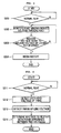
- FIG. 2 is a flow chart illustrating an operation in which an MCU controls a start operation, according to an embodiment of the present invention.
- FIG. 3 is a flow chart illustrating an operation in which the MCU compares the level of an induced voltage to control restart, according to an embodiment of the present invention.
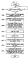
- FIG. 4 is a flow chart illustrating an operation in which the MCU compares the phase of a line voltage and the phase of the both-end voltage of a triac to control restart, according to an embodiment of the present invention.
- FIG. 5 is a flow chart illustrating start and restart operations by applying the electronic relay to a split-phase motor having no start capacitor, according to another embodiment of the present invention.
- FIG. 1 is a circuit diagram illustrating a driving circuit of a single phase induction motor to which an electronic relay is applied, according to an embodiment of the present invention.
- a single phase induction motor 200 includes a rotor and a stator.
- a run winding 1W and a start winding W2 are wound around the rotor.
- a start capacitor Cs is connected to the start winding W2 in series.
- An electronic relay 100 includes a power semiconductor switching device 110, a micro control unit (MCU) 130, and a control circuit 120.
- the power semiconductor switching device 110 is serially connected to the start winding W2 and controls (for example, breaks or flows) a current that flows in the start winding W2.
- the MCU 130 controls a start function according to a control algorithm that calculates the variation rate of a voltage (which is induced to the start winding W2) to derive a start torque.
- the control circuit 120 senses the voltages of motor lines L1 and L2 and the induced voltage of the start winding W2 to provide the sensed voltages to the MCU 130, and controls the power semiconductor switching device 110 according to the control of the MCU 130.
- the electronic relay 100 When start is completed by applying a power source to the single phase induction motor 200, the electronic relay 100 disconnects the start winding W2 from the power source lines L1 and L2. During the run of a motor, the electronic relay 100 senses the level of a voltage which is induced to the start winding W2 or the phase difference between a line voltage and the both-end voltage of the semiconductor switching device, and controls restart when necessary.
- the power semiconductor switching device 110 uses a snubberless traic Q1. As illustrated in FIG. 1 , the first port M1 of the triac Q1 is connected to the start capacitor Cs, and the second port M2 of the triac Q1 is connected to the start winding W2. The gate port G of the triac Q1 is connected to a transistor Q2, which is turned on/off according to the output OUT1 of the MCU 130 to generate a trigger signal, through a resistor R7.
- control circuit 120 includes an induced voltage detection circuit 122, a window comparison circuit 124, a discharge circuit 126, and a power source circuit 128.
- the induced voltage detection circuit 122 drops a voltage that is induced to the start winding W2 and connects the dropped voltage to the input port ADC1 of the MCU 130.
- the window comparison circuit 124 detects a zero-point voltage and a zero-point current by the use of the both-end voltage of the triac Q1 and provides the detected voltage and current to the first input port IN1 of the MCU 130.
- the discharge circuit 126 provides a discharge path for the start capacitor Cs.
- the power source circuit 128 provides a power source to the internal circuit of the relay 100.
- the induced voltage detection circuit 122 is configured with voltage drop resistors R8 and R9.
- the discharge circuit 126 is configured with a closed circuit that includes a run winding W1 which is serially connected to the one end of the start capacitor Cs, a first resistor R1 which is serially connected to the run winding W1, a tenth resistor R10 which is serially connected to the first resistor R1, and a second diode D2, wherein the one end of the second diode D2 is serially connected to the tenth resistor R10 and the other end of the second diode D2 is serially connected to the other end of the start capacitor Cs.
- Such a discharge circuit 126 gradually discharges the charge voltage of the start capacitor Cs. Since the power source circuit 128 is a common circuit, its detailed description will be omitted.
- the window comparison circuit 124 includes voltage drop resistors R3 and R4, voltage drop resistors R5 and R6, and a comparator U1.
- the voltage drop resistors R3 and R4 drop the both-end voltage of the triac Q1 to connect the dropped voltage to the positive (+) port of the comparator U1.
- the voltage drop resistors R5 and R6 drop a power source voltage VCC to connect the dropped voltage to the negative (-) port of the comparator U1.
- the comparator U1 compares the both-end voltage of the triac Q1, which is inputted to the positive (+) port, with the reference voltage of the negative (-) port to output the comparison result to the first input port IN1 of the MCU 130.
- the variable resistor R6 connected to the negative (-) port of the comparator U1 is connected to the second output port OUT2 of the MCU 130, and thereby the reference voltage of the negative (-) port may vary according to the second output OUT2 of the MCU 130.
- the MCU 130 outputs a first reference voltage for detecting the zero-point voltages of the lines L1 and L2 to the negative (-) port of the comparator U1 through the second output port OUT2 when the triac Q1 is turned off, and it outputs a second reference voltage for detecting the zero-point current of a start winding current to the negative (-) port of the comparator U1 through the second output port OUT2 when the triac Q1 is turned on.
- the comparator U1 uses the first reference voltage for detecting the zero-point voltage and the second reference voltage for detecting the zero-point current according to the control of the MCU 130, it configures the window comparison circuit 124 together with the both-end voltage input circuit of the triac Q1.
- the MCU 130 for executing the inherent algorithm includes a digital input port, a digital output port, an analog input port, an analog output port, an electrically erasable programmable read-only memory (EEPROM), and a timer.
- EEPROM electrically erasable programmable read-only memory
- the MCU 130 controls total operations in connection with the control circuit 120.
- the MCU 130 receives the output of the comparator U1 through the first input port IN1, and detects the phase of the line voltage through the second input port IN2.
- the MCU 130 receives a voltage, which is induced to the start winding W2, through the input port ADC1, and derives a start torque with the variation rate of the induced voltage to determine a start completion time.
- the MCU 130 detects a zero voltage/current to efficiently control the gate of the triac Q1 through the first output port OUT1.
- the electronic relay 100 operates through the organic connection of the control circuit 120 and the MCU 130, and therefore, for convenience, its operations will be described below with reference to FIGS. 2 to 5 .
- FIG. 2 is a flow chart illustrating an operation in which the MCU controls a start operation, according to an embodiment of the present invention.
- the power source circuit 128 supplies the power source voltage VCC to a relay circuit, and the MCU 130 determines whether the motor 200 is a capacitor start motor or a split-phase start motor that is connected to a start capacitor Cs.
- the motor 200 is the capacitor start motor, the motor 200 outputs the first reference voltage as the reference voltage of the comparator U1 through the second output port OUT2.
- the first reference voltage is a reference voltage for detecting the zero-point voltage of a motor line voltage, in operations S201 and S202.
- the both-end voltage of the triac Q1 is dropped through the resistors R3 and R4 to become the input voltage of the comparator U1, and the divided voltage of the power source voltage VCC becomes the first reference voltage according to the output OUT2 of the MCU 130.
- the output of the comparator U1 is inputted to the input port IN1 of the MCU 130.
- the MCU 130 senses the output signal of the comparator U1 through the input port IN1 to check the zero-point voltage of the both ends of the triac Q1, and a trigger pulse signal is outputted to the output port OUT1 for controlling the gate G of the triac Q1.
- a gate current is applied to the gate G of the triac Q1 through the transistor Q2 and the resistor R7 (which configure a control circuit for controlling the gate G of the triac Q1) according to the output OUT1 of the MCU 130, the triac Q1 is turned on at a zero-point voltage.
- the triac Q1 When a pulse higher than a trigger voltage is applied to the gate G of the traic Q1, the triac Q1 is turned on.
- the triac Q1 continuously maintains a turn-on state while a current is flowing between ports M1 and M2 thereof and then, when the current between the ports M1 and M2 becomes lower than the maintained current, the triac Q1 is turned off. Accordingly, when an alternating current (AC) current flows in the ports M1 and M2, since the triac Q1 is again turned off at the zero-point current of a current (which is produced at the every half cycle of an AC current) in operation characteristic, the gate G of the triac Q1 should be again triggered at the time for maintaining the turn-on state of the triac Q1.
- AC alternating current
- the window comparison circuit 124 changes the signal of the MCU 130 at every half cycle in which a start winding current is closer to a zero-point current, Therefore, the MCU 130 applies a trigger current to the gate G of the triac Q1 through the output port OUT1 and the transistor Q2 to maintain the turn-on state of the triac Q1, in operations S206 to S209.
- the gate current level of the triac is an important factor for improving the inherent characteristic (dv/dt(commutation)) of the triac.
- the electronic relay 100 can stably control the triac while minimizing internal power consumption thereof.
- the triac Q1 varies according to component characteristic and peripheral temperature between the ports M1 and M2 (which are the main contacts of the traic Q1) at every half cycle in which a start winding current traverses a zero-point current, in a turned-on state, wherein the voltage variation of about 1.0 to 1.5 V occurs. Accordingly, the electronic relay 100 predicts the zero-point current time of a start winding current through the both-end voltage variation of the triac Q1, and it applies an enough amount of current to the gate G of the triac Q1 for the minimum delay time to efficiently control the triac Q1 at the predicted time.
- the both-end voltage of the triac Q1 is dropped through the resistors R3 and R4 to become the input voltage of the positive (+) port of the comparator U1.
- the resistors R5 and R6 set the reference voltage of the negative (-) port of the comparator U1.
- the comparator U1 compares the input voltage of the positive (+) port with the reference voltage of the negative (-) voltage to sense the phase inversion of the triac Q1 (i.e., the zero-point voltage pass time, of a motor line voltage before start, and the zero-point current pass time of a start winding current during start), and provides the sensed result to the MCU 130 through the input port IN1.
- the MCU 130 adjusts the high limit and low limit of the reference voltage of the negative (-) port of the comparator U1 according to the phase inversion of the start winding current that occurs at the every half cycle of an AC power source.
- the triac Q1 and peripheral circuits can be protected from the both-end noise (for example, a surge voltage and an impulse voltage) of the triac Q1 and the charge voltage of the start capacitor.
- the single phase induction motor 200 begins starting and a rotator begins rotating, magnetic flux by a current flowing in a rotator winding is produced, and a voltage is induced to the start winding W2 by means of the magnetic flux.
- the induced voltage increases in proportion to an angular velocity and then becomes constant when the motor 200 is closer to a synch speed to complete start.
- the induced voltage of the start winding W2 is inputted to the analog input port ADC1 of the MCU 130 through the resistors R8 and R9 of the induced voltage detection circuit 122, and is converted into a digital value by the analog-to-digital converter of the MCU 130.
- the digital-converted induced voltage is stored in a flash memory of the MCU 130.
- the MCU 130 calculates the variation rate of the induced voltage being proportional to the acceleration speed of the motor 200 to check the time in which the start torque of the motor 200 is the maxim.um, and when the start torque of the motor 200 begins decreasing rapidly, the MCU 130 limits the gate current of the triac Q1 through the resistor R7 and the transistor Q2 to turn off the triac Q1, thereby breaking the start winding W2 in operations 210 to S213.
- the maximum torque occurs at a time in which an angular velocity becomes 70 % to 80 % of a synch speed.
- relationships between a motor torque, a load torque, an acceleration torque and an induced voltage variation rate (dVs/dt) will be defined as follows. The following description will be made on a method for detecting the maximum torque necessary for the start control of the single phase induction motor 200 during start.
- a current which is applied to the run winding W1 and start winding W2 of a stator during start, produces a rotation magnetic field.
- a rotation magnetic field passes a rotator, a voltage is produced in the rotator, and a current is produced in the rotator by the voltage of the rotator.
- a magnetic field is also produced in the periphery of the rotator, and a voltage is induced to the start winding W2 by the magnetic field.
- the induced voltage (Vs) is also called a speed voltage because the level of the induced voltage (Vs) is proportional to the angular velocity ( ⁇ ) of the rotator.
- a motor torque is proportional to the sum of a load torque and an acceleration torque as expressed in Equation (1) below.
- the start torque of the motor increases in proportion to the acceleration torque or induced voltage variation rate of the motor 200.
- the MCU 130 receives a voltage induced to the start winding W2 through the input port ADC1 to calculate the variation rate of the induced voltage, and thus the occurrence time of the maximum torque can be checked while the motor 200 is starting. Accordingly, the decrease time of the start torque of the motor 200 can also be sensed accurately.
- a stator magnetic field ( ⁇ ) increases in proportion to the voltage of the stator or a motor voltage as expressed in Equation (2) below.
- a rotor induced voltage (E) is proportional to the intensity of the stator magnetic field and the angular velocity (N) of the rotor.
- the speed (N) of the motor i.e., the angular velocity (N) of the rotator
- N the speed of the motor
- FIG. 3 is a flow chart illustrating an operation in which the MCU compares the level of the induced voltage to control restart, according to an embodiment of the present invention.
- FIG. 4 is a flow chart illustrating an operation in which the MCU compares the phase of a line voltage and the phase of the both-end voltage of the triac to control restart, according to an embodiment of the present invention,
- the MCU 130 receives the start winding induced voltage (E') being proportional to the angular velocity through the input port ADC1 to perform monitoring when the motor 200 normally runs, in operations S301 and S302.
- the MCU 130 continuously checks the level of the induced voltage (E'). When the level of the induced voltage is closer to the induced voltage of a locked rotor speed, the MCU 130 determines as that in which the speed of the motor 200 becomes close to the locked rotor speed, and the MCU 130 controls the triac Q1 to perform restart through the above-described operations, in operations S303 and S304.
- the MCU 130 may accumulatively store the phase difference between the both-end voltage of the triac Q1 and the line voltage and then may check the change of the phase difference to perform restart.
- the MCU 130 detects the phase of the both-end voltage of the triac Q1 through the input port IN1, detects the phase of the line voltage through the input port IN1, and thereby determines whether to restart with the phase difference between the both-end voltage of the triac Q1 and the line voltage, in operations S311 to S314. For example, the MCU 130 continuously senses the phase difference between the both-end voltage of the triac Q1 and the line voltage, and then when the phase difference between the two voltages decreases to a value less than a certain value, the MCU 130 triggers the gate of the triac Q1 to restart.
- the MCU 130 may determine as the switching of a forward/reverse wiring or a reverse run due to impulse and may restart. That is, when the forward/reverse wiring is switched, a momentary forward/reverse rotation having no arc may be performed. When an undesired reverse run due to impulse, the MCU 130 may return the run of the motor 200 to a forward run.
- FIG. 5 is a flow chart illustrating start and restart operations by applying the electronic relay to a split-phase motor having no start capacitor, according to another embodiment of the present invention.
- the split-phase motor checks a time when a start torque is the maximum, in the method of a capacitor motor, to predict a start completion time. Accordingly, when the electronic relay 100 is applied to the split-phase motor, a locked rotor current is greater by five to seven orders of magnitude than a run current.
- the MCU 130 controls the triac Q1 at a time when a current rapidly decreases and thereby the phase difference between the motor line voltage and the start winding current rapidly increases.
- the phase difference of about 20° to 30° occurs between the motor line voltage and the start winding current according to a winding scheme when the triac Q1 is turned on and the motor 200 begins starting.
- the start winding current decreases due to a. voltage that is induced to the start winding W2, and thus the phase difference between the motor line voltage and the start winding current increases rapidly. Because the start winding current is in-phase with the both-end voltage of the triac Q1, the phase of the start winding current may be detected with the both-end voltage of the triac Q1.
- the MCU 130 receives the output of the comparator U1 corresponding to the both-end voltage of the triac Q1 through the input port IN1 to detect the current phase of the start winding W2, detects the phase of the motor line voltage though the input port IN2, and checks a time when the phase difference between the start winding current and the line voltage increases. When the change of the phase difference becomes slow, the MCU 130 predicts as the completion of start to turn off the triac Q1 within a certain delay time, in operations S401 to S405.
- the phase inversion of the start winding current is performed through the window comparison circuit 124 that is used as a zero-point current/voltage detection circuit, and a zero-point voltage corresponding to the phase inversion of the line voltage is inputted to the input port IN2 of the MCU 130 through a current limiting resistor R12.
- the MCU 130 determines as that in which the motor 200 is in a locked state during start and instantly turns off the triac Q1, thereby protecting the start winding W2.
- a motor speed sense scheme using the detection of an induced voltage may be applied for the restart of the motor 200 during a normal run, like a capacitor start motor, a low-cost circuit may be configured using the following phase difference comparison scheme without a separate analog-to-digital converter.
- the vector sum of the motor line voltage and the induced voltage is applied across the both ends of the triac Q1 while the motor 200 is running, and thus a phase difference with respect to the line voltage occurs.
- the phase difference between the both-end voltage of the triac Q1 and the line voltage decreases. Accordingly, the phase difference between the both-end voltage of the triac Q1 and the line voltage is continuously sensed, and when the phase difference between the two voltages decreases to a value less than a certain value, the MCU 130 triggers the gate of the triac Q1 to restart, in operations S406 to S409.
- the electronic relay 100 senses the phase difference between the motor line voltage and the start winding current during start, and senses the phase difference between the motor line voltage and the both-end voltage of the triac Q1 during run, thereby restarting when necessary.
Landscapes
- Engineering & Computer Science (AREA)
- Power Engineering (AREA)
- Control Of Ac Motors In General (AREA)
- Motor And Converter Starters (AREA)
Applications Claiming Priority (1)
| Application Number | Priority Date | Filing Date | Title |
|---|---|---|---|
| KR1020090068382A KR101053759B1 (ko) | 2009-07-27 | 2009-07-27 | 단상 유도전동기의 기동방법 및 이를 이용한 전자식 계전기 |
Publications (3)
| Publication Number | Publication Date |
|---|---|
| EP2280475A2 true EP2280475A2 (de) | 2011-02-02 |
| EP2280475A3 EP2280475A3 (de) | 2016-01-13 |
| EP2280475B1 EP2280475B1 (de) | 2018-07-04 |
Family
ID=43357965
Family Applications (1)
| Application Number | Title | Priority Date | Filing Date |
|---|---|---|---|
| EP10002989.1A Active EP2280475B1 (de) | 2009-07-27 | 2010-03-22 | Verfahren zum Starten eines Einphasen-Asynchronmotors und elektronisches Relais, das dieses anwendet |
Country Status (3)
| Country | Link |
|---|---|
| US (1) | US8120305B2 (de) |
| EP (1) | EP2280475B1 (de) |
| KR (1) | KR101053759B1 (de) |
Cited By (1)
| Publication number | Priority date | Publication date | Assignee | Title |
|---|---|---|---|---|
| JP2011045223A (ja) * | 2009-08-24 | 2011-03-03 | Eishun Kin | 単相誘導電動機の起動方法及びこれを用いる電子リレー |
Families Citing this family (10)
| Publication number | Priority date | Publication date | Assignee | Title |
|---|---|---|---|---|
| CN102386899A (zh) * | 2011-11-10 | 2012-03-21 | 蓝星化工新材料股份有限公司广西分公司 | 一种时间继电器 |
| JP5604566B1 (ja) * | 2013-07-05 | 2014-10-08 | 株式会社フジクラ | メンブレンスイッチ及び座席装置 |
| CN104201939B (zh) * | 2014-08-19 | 2017-06-13 | 深圳朗特智能控制股份有限公司 | 一种交流马达的控制系统 |
| US11855558B2 (en) | 2018-02-27 | 2023-12-26 | Premier Energy Holdings, Inc. | AC start, solar run hybrid solution for single phase, starting capacitor, motor applications with solar power measurement |
| US10840831B2 (en) * | 2018-02-27 | 2020-11-17 | Premier Energy Holdings, Inc. | Solar hybrid solution for single phase starting capacitor motor applications with grid start |
| US20220209693A1 (en) * | 2020-12-28 | 2022-06-30 | Global Mixed-Mode Technology Inc. | Motor unit |
| CN113141128B (zh) * | 2021-03-31 | 2022-07-15 | 首钢京唐钢铁联合有限责任公司 | 一种绕线电机转子串电阻启动故障检测方法、装置及系统 |
| US11722090B2 (en) | 2021-04-21 | 2023-08-08 | Emerson Electric Co. | Control circuits for compressor motors including multiple capacitors |
| US12244188B2 (en) | 2021-04-21 | 2025-03-04 | Copeland Lp | Induction motors including speed sensing circuits for motor control |
| US12199530B2 (en) | 2021-04-21 | 2025-01-14 | InSinkErator LLC | Control circuits for disposer motors |
Family Cites Families (8)
| Publication number | Priority date | Publication date | Assignee | Title |
|---|---|---|---|---|
| US4204425A (en) * | 1978-06-29 | 1980-05-27 | Westinghouse Electric Corp. | Method of testing induction motors |
| US4843295A (en) * | 1987-06-04 | 1989-06-27 | Texas Instruments Incorporated | Method and apparatus for starting single phase motors |
| US5038091A (en) * | 1989-08-11 | 1991-08-06 | Whirlpool Corporation | Electronic control for an appliance |
| US5528120A (en) * | 1994-09-09 | 1996-06-18 | Sealed Unit Parts Co., Inc. | Adjustable electronic potential relay |
| US6320348B1 (en) * | 1999-06-14 | 2001-11-20 | Andrew S. Kadah | Time rate of change motor start circuit |
| KR100889186B1 (ko) * | 2007-07-20 | 2009-03-17 | 김영준 | 단상 유도전동기의 기동용 계전기 |
| KR20070116570A (ko) * | 2007-11-07 | 2007-12-10 | 김영준 | 단상 유도전동기의 기동용 계전기의 개량방법 |
| KR100957681B1 (ko) * | 2008-02-11 | 2010-05-12 | 김영준 | 분상 기동형 단상 유도 전동기의 기동 장치 |
-
2009
- 2009-07-27 KR KR1020090068382A patent/KR101053759B1/ko active Active
- 2009-08-20 US US12/544,289 patent/US8120305B2/en active Active
-
2010
- 2010-03-22 EP EP10002989.1A patent/EP2280475B1/de active Active
Non-Patent Citations (1)
| Title |
|---|
| None |
Cited By (1)
| Publication number | Priority date | Publication date | Assignee | Title |
|---|---|---|---|---|
| JP2011045223A (ja) * | 2009-08-24 | 2011-03-03 | Eishun Kin | 単相誘導電動機の起動方法及びこれを用いる電子リレー |
Also Published As
| Publication number | Publication date |
|---|---|
| KR20110010978A (ko) | 2011-02-08 |
| US20110018486A1 (en) | 2011-01-27 |
| US8120305B2 (en) | 2012-02-21 |
| EP2280475A3 (de) | 2016-01-13 |
| EP2280475B1 (de) | 2018-07-04 |
| KR101053759B1 (ko) | 2011-08-02 |
Similar Documents
| Publication | Publication Date | Title |
|---|---|---|
| EP2280475B1 (de) | Verfahren zum Starten eines Einphasen-Asynchronmotors und elektronisches Relais, das dieses anwendet | |
| JP3668516B2 (ja) | ブラシレス直流電動機の速度制御方法およびブラシレス直流電動機 | |
| JP4277919B2 (ja) | モータ駆動装置及びモータ駆動制御方法 | |
| US10910979B2 (en) | Motor drive control device and motor drive control method | |
| EP2538545B1 (de) | Sensorfreie Steuerungseinheit für bürstenlosen Gleichstrommotor | |
| US9777738B2 (en) | Anti-air-return system and method of fan | |
| WO2009148197A1 (en) | Electronic relay for single phase induction motor | |
| CN102025299B (zh) | 用于启动单相感应电动机和相应的电子继电器的方法 | |
| US7095207B1 (en) | Load and speed sensitive motor starting circuit and method | |
| JP2002354874A (ja) | ブラシレス直流電動機の異常状態検出方法及び保護方法 | |
| US11303233B2 (en) | Motor drive control device | |
| US20130015792A1 (en) | Motor driving circuit and motor device | |
| KR20110008666A (ko) | 유도전동기의 유연기동장치 및 방법 | |
| JP6375758B2 (ja) | モータ制御装置およびそれを用いた空気調和機 | |
| JP4948581B2 (ja) | 単相誘導電動機の起動方法及びこれを用いる電子リレー | |
| JPH06253580A (ja) | インバータ装置の保護装置 | |
| US12155338B2 (en) | Motor driver having motor abnormality detection mechanism | |
| KR100956488B1 (ko) | 인버터를 지락으로부터 보호하기 위한 장치 및 방법 | |
| US9742340B2 (en) | Apparatus for controlling inverter | |
| US12199530B2 (en) | Control circuits for disposer motors | |
| US7202627B1 (en) | Load and speed sensitive motor starting circuit and method | |
| KR101591642B1 (ko) | 모터 드라이버 | |
| CN110995074B (zh) | 马达控制装置以及马达装置 | |
| JPH06209581A (ja) | インバータ装置の保護装置 | |
| JPH0947076A (ja) | ブラシレスモータの制御方法 |
Legal Events
| Date | Code | Title | Description |
|---|---|---|---|
| PUAI | Public reference made under article 153(3) epc to a published international application that has entered the european phase |
Free format text: ORIGINAL CODE: 0009012 |
|
| AK | Designated contracting states |
Kind code of ref document: A2 Designated state(s): AT BE BG CH CY CZ DE DK EE ES FI FR GB GR HR HU IE IS IT LI LT LU LV MC MK MT NL NO PL PT RO SE SI SK SM TR |
|
| AX | Request for extension of the european patent |
Extension state: AL BA ME RS |
|
| PUAL | Search report despatched |
Free format text: ORIGINAL CODE: 0009013 |
|
| AK | Designated contracting states |
Kind code of ref document: A3 Designated state(s): AT BE BG CH CY CZ DE DK EE ES FI FR GB GR HR HU IE IS IT LI LT LU LV MC MK MT NL NO PL PT RO SE SI SK SM TR |
|
| AX | Request for extension of the european patent |
Extension state: AL BA ME RS |
|
| RIC1 | Information provided on ipc code assigned before grant |
Ipc: H02P 1/02 20060101ALI20151207BHEP Ipc: H02P 1/42 20060101AFI20151207BHEP |
|
| 17P | Request for examination filed |
Effective date: 20160712 |
|
| RBV | Designated contracting states (corrected) |
Designated state(s): AT BE BG CH CY CZ DE DK EE ES FI FR GB GR HR HU IE IS IT LI LT LU LV MC MK MT NL NO PL PT RO SE SI SK SM TR |
|
| GRAP | Despatch of communication of intention to grant a patent |
Free format text: ORIGINAL CODE: EPIDOSNIGR1 |
|
| STAA | Information on the status of an ep patent application or granted ep patent |
Free format text: STATUS: GRANT OF PATENT IS INTENDED |
|
| INTG | Intention to grant announced |
Effective date: 20171107 |
|
| GRAS | Grant fee paid |
Free format text: ORIGINAL CODE: EPIDOSNIGR3 |
|
| GRAA | (expected) grant |
Free format text: ORIGINAL CODE: 0009210 |
|
| STAA | Information on the status of an ep patent application or granted ep patent |
Free format text: STATUS: THE PATENT HAS BEEN GRANTED |
|
| AK | Designated contracting states |
Kind code of ref document: B1 Designated state(s): AT BE BG CH CY CZ DE DK EE ES FI FR GB GR HR HU IE IS IT LI LT LU LV MC MK MT NL NO PL PT RO SE SI SK SM TR |
|
| RAP1 | Party data changed (applicant data changed or rights of an application transferred) |
Owner name: KIM, YOUNG-JUN |
|
| REG | Reference to a national code |
Ref country code: GB Ref legal event code: FG4D |
|
| RIN1 | Information on inventor provided before grant (corrected) |
Inventor name: KIM, YOUNG-JUN |
|
| REG | Reference to a national code |
Ref country code: CH Ref legal event code: EP |
|
| REG | Reference to a national code |
Ref country code: AT Ref legal event code: REF Ref document number: 1015577 Country of ref document: AT Kind code of ref document: T Effective date: 20180715 |
|
| REG | Reference to a national code |
Ref country code: IE Ref legal event code: FG4D |
|
| REG | Reference to a national code |
Ref country code: DE Ref legal event code: R096 Ref document number: 602010051589 Country of ref document: DE |
|
| REG | Reference to a national code |
Ref country code: NL Ref legal event code: MP Effective date: 20180704 |
|
| REG | Reference to a national code |
Ref country code: LT Ref legal event code: MG4D |
|
| REG | Reference to a national code |
Ref country code: AT Ref legal event code: MK05 Ref document number: 1015577 Country of ref document: AT Kind code of ref document: T Effective date: 20180704 |
|
| PG25 | Lapsed in a contracting state [announced via postgrant information from national office to epo] |
Ref country code: NL Free format text: LAPSE BECAUSE OF FAILURE TO SUBMIT A TRANSLATION OF THE DESCRIPTION OR TO PAY THE FEE WITHIN THE PRESCRIBED TIME-LIMIT Effective date: 20180704 |
|
| PG25 | Lapsed in a contracting state [announced via postgrant information from national office to epo] |
Ref country code: PL Free format text: LAPSE BECAUSE OF FAILURE TO SUBMIT A TRANSLATION OF THE DESCRIPTION OR TO PAY THE FEE WITHIN THE PRESCRIBED TIME-LIMIT Effective date: 20180704 Ref country code: CZ Free format text: LAPSE BECAUSE OF FAILURE TO SUBMIT A TRANSLATION OF THE DESCRIPTION OR TO PAY THE FEE WITHIN THE PRESCRIBED TIME-LIMIT Effective date: 20180704 Ref country code: LT Free format text: LAPSE BECAUSE OF FAILURE TO SUBMIT A TRANSLATION OF THE DESCRIPTION OR TO PAY THE FEE WITHIN THE PRESCRIBED TIME-LIMIT Effective date: 20180704 Ref country code: BG Free format text: LAPSE BECAUSE OF FAILURE TO SUBMIT A TRANSLATION OF THE DESCRIPTION OR TO PAY THE FEE WITHIN THE PRESCRIBED TIME-LIMIT Effective date: 20181004 Ref country code: SE Free format text: LAPSE BECAUSE OF FAILURE TO SUBMIT A TRANSLATION OF THE DESCRIPTION OR TO PAY THE FEE WITHIN THE PRESCRIBED TIME-LIMIT Effective date: 20180704 Ref country code: AT Free format text: LAPSE BECAUSE OF FAILURE TO SUBMIT A TRANSLATION OF THE DESCRIPTION OR TO PAY THE FEE WITHIN THE PRESCRIBED TIME-LIMIT Effective date: 20180704 Ref country code: NO Free format text: LAPSE BECAUSE OF FAILURE TO SUBMIT A TRANSLATION OF THE DESCRIPTION OR TO PAY THE FEE WITHIN THE PRESCRIBED TIME-LIMIT Effective date: 20181004 Ref country code: IS Free format text: LAPSE BECAUSE OF FAILURE TO SUBMIT A TRANSLATION OF THE DESCRIPTION OR TO PAY THE FEE WITHIN THE PRESCRIBED TIME-LIMIT Effective date: 20181104 Ref country code: FI Free format text: LAPSE BECAUSE OF FAILURE TO SUBMIT A TRANSLATION OF THE DESCRIPTION OR TO PAY THE FEE WITHIN THE PRESCRIBED TIME-LIMIT Effective date: 20180704 Ref country code: GR Free format text: LAPSE BECAUSE OF FAILURE TO SUBMIT A TRANSLATION OF THE DESCRIPTION OR TO PAY THE FEE WITHIN THE PRESCRIBED TIME-LIMIT Effective date: 20181005 |
|
| PG25 | Lapsed in a contracting state [announced via postgrant information from national office to epo] |
Ref country code: ES Free format text: LAPSE BECAUSE OF FAILURE TO SUBMIT A TRANSLATION OF THE DESCRIPTION OR TO PAY THE FEE WITHIN THE PRESCRIBED TIME-LIMIT Effective date: 20180704 Ref country code: HR Free format text: LAPSE BECAUSE OF FAILURE TO SUBMIT A TRANSLATION OF THE DESCRIPTION OR TO PAY THE FEE WITHIN THE PRESCRIBED TIME-LIMIT Effective date: 20180704 Ref country code: LV Free format text: LAPSE BECAUSE OF FAILURE TO SUBMIT A TRANSLATION OF THE DESCRIPTION OR TO PAY THE FEE WITHIN THE PRESCRIBED TIME-LIMIT Effective date: 20180704 |
|
| REG | Reference to a national code |
Ref country code: DE Ref legal event code: R097 Ref document number: 602010051589 Country of ref document: DE |
|
| PG25 | Lapsed in a contracting state [announced via postgrant information from national office to epo] |
Ref country code: EE Free format text: LAPSE BECAUSE OF FAILURE TO SUBMIT A TRANSLATION OF THE DESCRIPTION OR TO PAY THE FEE WITHIN THE PRESCRIBED TIME-LIMIT Effective date: 20180704 Ref country code: IT Free format text: LAPSE BECAUSE OF FAILURE TO SUBMIT A TRANSLATION OF THE DESCRIPTION OR TO PAY THE FEE WITHIN THE PRESCRIBED TIME-LIMIT Effective date: 20180704 Ref country code: RO Free format text: LAPSE BECAUSE OF FAILURE TO SUBMIT A TRANSLATION OF THE DESCRIPTION OR TO PAY THE FEE WITHIN THE PRESCRIBED TIME-LIMIT Effective date: 20180704 |
|
| PLBE | No opposition filed within time limit |
Free format text: ORIGINAL CODE: 0009261 |
|
| STAA | Information on the status of an ep patent application or granted ep patent |
Free format text: STATUS: NO OPPOSITION FILED WITHIN TIME LIMIT |
|
| PG25 | Lapsed in a contracting state [announced via postgrant information from national office to epo] |
Ref country code: SK Free format text: LAPSE BECAUSE OF FAILURE TO SUBMIT A TRANSLATION OF THE DESCRIPTION OR TO PAY THE FEE WITHIN THE PRESCRIBED TIME-LIMIT Effective date: 20180704 Ref country code: SM Free format text: LAPSE BECAUSE OF FAILURE TO SUBMIT A TRANSLATION OF THE DESCRIPTION OR TO PAY THE FEE WITHIN THE PRESCRIBED TIME-LIMIT Effective date: 20180704 Ref country code: DK Free format text: LAPSE BECAUSE OF FAILURE TO SUBMIT A TRANSLATION OF THE DESCRIPTION OR TO PAY THE FEE WITHIN THE PRESCRIBED TIME-LIMIT Effective date: 20180704 |
|
| 26N | No opposition filed |
Effective date: 20190405 |
|
| PG25 | Lapsed in a contracting state [announced via postgrant information from national office to epo] |
Ref country code: SI Free format text: LAPSE BECAUSE OF FAILURE TO SUBMIT A TRANSLATION OF THE DESCRIPTION OR TO PAY THE FEE WITHIN THE PRESCRIBED TIME-LIMIT Effective date: 20180704 |
|
| PG25 | Lapsed in a contracting state [announced via postgrant information from national office to epo] |
Ref country code: MC Free format text: LAPSE BECAUSE OF FAILURE TO SUBMIT A TRANSLATION OF THE DESCRIPTION OR TO PAY THE FEE WITHIN THE PRESCRIBED TIME-LIMIT Effective date: 20180704 |
|
| REG | Reference to a national code |
Ref country code: CH Ref legal event code: PL |
|
| GBPC | Gb: european patent ceased through non-payment of renewal fee |
Effective date: 20190322 |
|
| PG25 | Lapsed in a contracting state [announced via postgrant information from national office to epo] |
Ref country code: LU Free format text: LAPSE BECAUSE OF NON-PAYMENT OF DUE FEES Effective date: 20190322 |
|
| REG | Reference to a national code |
Ref country code: BE Ref legal event code: MM Effective date: 20190331 |
|
| PG25 | Lapsed in a contracting state [announced via postgrant information from national office to epo] |
Ref country code: IE Free format text: LAPSE BECAUSE OF NON-PAYMENT OF DUE FEES Effective date: 20190322 Ref country code: GB Free format text: LAPSE BECAUSE OF NON-PAYMENT OF DUE FEES Effective date: 20190322 Ref country code: CH Free format text: LAPSE BECAUSE OF NON-PAYMENT OF DUE FEES Effective date: 20190331 Ref country code: LI Free format text: LAPSE BECAUSE OF NON-PAYMENT OF DUE FEES Effective date: 20190331 |
|
| PG25 | Lapsed in a contracting state [announced via postgrant information from national office to epo] |
Ref country code: BE Free format text: LAPSE BECAUSE OF NON-PAYMENT OF DUE FEES Effective date: 20190331 |
|
| PGFP | Annual fee paid to national office [announced via postgrant information from national office to epo] |
Ref country code: DE Payment date: 20200317 Year of fee payment: 11 |
|
| PG25 | Lapsed in a contracting state [announced via postgrant information from national office to epo] |
Ref country code: PT Free format text: LAPSE BECAUSE OF FAILURE TO SUBMIT A TRANSLATION OF THE DESCRIPTION OR TO PAY THE FEE WITHIN THE PRESCRIBED TIME-LIMIT Effective date: 20181105 Ref country code: MT Free format text: LAPSE BECAUSE OF NON-PAYMENT OF DUE FEES Effective date: 20190322 |
|
| PGFP | Annual fee paid to national office [announced via postgrant information from national office to epo] |
Ref country code: FR Payment date: 20200326 Year of fee payment: 11 |
|
| PG25 | Lapsed in a contracting state [announced via postgrant information from national office to epo] |
Ref country code: CY Free format text: LAPSE BECAUSE OF FAILURE TO SUBMIT A TRANSLATION OF THE DESCRIPTION OR TO PAY THE FEE WITHIN THE PRESCRIBED TIME-LIMIT Effective date: 20180704 |
|
| PG25 | Lapsed in a contracting state [announced via postgrant information from national office to epo] |
Ref country code: HU Free format text: LAPSE BECAUSE OF FAILURE TO SUBMIT A TRANSLATION OF THE DESCRIPTION OR TO PAY THE FEE WITHIN THE PRESCRIBED TIME-LIMIT; INVALID AB INITIO Effective date: 20100322 |
|
| REG | Reference to a national code |
Ref country code: DE Ref legal event code: R119 Ref document number: 602010051589 Country of ref document: DE |
|
| PG25 | Lapsed in a contracting state [announced via postgrant information from national office to epo] |
Ref country code: DE Free format text: LAPSE BECAUSE OF NON-PAYMENT OF DUE FEES Effective date: 20211001 Ref country code: FR Free format text: LAPSE BECAUSE OF NON-PAYMENT OF DUE FEES Effective date: 20210331 |
|
| PG25 | Lapsed in a contracting state [announced via postgrant information from national office to epo] |
Ref country code: MK Free format text: LAPSE BECAUSE OF FAILURE TO SUBMIT A TRANSLATION OF THE DESCRIPTION OR TO PAY THE FEE WITHIN THE PRESCRIBED TIME-LIMIT Effective date: 20180704 |
|
| PGFP | Annual fee paid to national office [announced via postgrant information from national office to epo] |
Ref country code: TR Payment date: 20260220 Year of fee payment: 17 |