EP2280236B1 - Wärmeableitende Rippen, Kühlkörper für einen großen Bereich mit den wärmeableitenden Rippen und Herstellungsverfahren dafür - Google Patents
Wärmeableitende Rippen, Kühlkörper für einen großen Bereich mit den wärmeableitenden Rippen und Herstellungsverfahren dafür Download PDFInfo
- Publication number
- EP2280236B1 EP2280236B1 EP09009941.7A EP09009941A EP2280236B1 EP 2280236 B1 EP2280236 B1 EP 2280236B1 EP 09009941 A EP09009941 A EP 09009941A EP 2280236 B1 EP2280236 B1 EP 2280236B1
- Authority
- EP
- European Patent Office
- Prior art keywords
- heat
- fin
- heat sink
- large area
- fins
- Prior art date
- Legal status (The legal status is an assumption and is not a legal conclusion. Google has not performed a legal analysis and makes no representation as to the accuracy of the status listed.)
- Not-in-force
Links
Images


Classifications
-
- F—MECHANICAL ENGINEERING; LIGHTING; HEATING; WEAPONS; BLASTING
- F28—HEAT EXCHANGE IN GENERAL
- F28D—HEAT-EXCHANGE APPARATUS, NOT PROVIDED FOR IN ANOTHER SUBCLASS, IN WHICH THE HEAT-EXCHANGE MEDIA DO NOT COME INTO DIRECT CONTACT
- F28D15/00—Heat-exchange apparatus with the intermediate heat-transfer medium in closed tubes passing into or through the conduit walls ; Heat-exchange apparatus employing intermediate heat-transfer medium or bodies
- F28D15/02—Heat-exchange apparatus with the intermediate heat-transfer medium in closed tubes passing into or through the conduit walls ; Heat-exchange apparatus employing intermediate heat-transfer medium or bodies in which the medium condenses and evaporates, e.g. heat pipes
- F28D15/0233—Heat-exchange apparatus with the intermediate heat-transfer medium in closed tubes passing into or through the conduit walls ; Heat-exchange apparatus employing intermediate heat-transfer medium or bodies in which the medium condenses and evaporates, e.g. heat pipes the conduits having a particular shape, e.g. non-circular cross-section, annular
-
- H—ELECTRICITY
- H01—ELECTRIC ELEMENTS
- H01L—SEMICONDUCTOR DEVICES NOT COVERED BY CLASS H10
- H01L21/00—Processes or apparatus adapted for the manufacture or treatment of semiconductor or solid state devices or of parts thereof
- H01L21/02—Manufacture or treatment of semiconductor devices or of parts thereof
- H01L21/04—Manufacture or treatment of semiconductor devices or of parts thereof the devices having potential barriers, e.g. a PN junction, depletion layer or carrier concentration layer
- H01L21/48—Manufacture or treatment of parts, e.g. containers, prior to assembly of the devices, using processes not provided for in a single one of the groups H01L21/18 - H01L21/326 or H10D48/04 - H10D48/07
- H01L21/4814—Conductive parts
- H01L21/4871—Bases, plates or heatsinks
- H01L21/4882—Assembly of heatsink parts
-
- H—ELECTRICITY
- H01—ELECTRIC ELEMENTS
- H01L—SEMICONDUCTOR DEVICES NOT COVERED BY CLASS H10
- H01L23/00—Details of semiconductor or other solid state devices
- H01L23/34—Arrangements for cooling, heating, ventilating or temperature compensation ; Temperature sensing arrangements
- H01L23/42—Fillings or auxiliary members in containers or encapsulations selected or arranged to facilitate heating or cooling
- H01L23/427—Cooling by change of state, e.g. use of heat pipes
-
- H—ELECTRICITY
- H01—ELECTRIC ELEMENTS
- H01L—SEMICONDUCTOR DEVICES NOT COVERED BY CLASS H10
- H01L23/00—Details of semiconductor or other solid state devices
- H01L23/34—Arrangements for cooling, heating, ventilating or temperature compensation ; Temperature sensing arrangements
- H01L23/46—Arrangements for cooling, heating, ventilating or temperature compensation ; Temperature sensing arrangements involving the transfer of heat by flowing fluids
- H01L23/467—Arrangements for cooling, heating, ventilating or temperature compensation ; Temperature sensing arrangements involving the transfer of heat by flowing fluids by flowing gases, e.g. air
-
- F—MECHANICAL ENGINEERING; LIGHTING; HEATING; WEAPONS; BLASTING
- F28—HEAT EXCHANGE IN GENERAL
- F28F—DETAILS OF HEAT-EXCHANGE AND HEAT-TRANSFER APPARATUS, OF GENERAL APPLICATION
- F28F2215/00—Fins
-
- H—ELECTRICITY
- H01—ELECTRIC ELEMENTS
- H01L—SEMICONDUCTOR DEVICES NOT COVERED BY CLASS H10
- H01L23/00—Details of semiconductor or other solid state devices
- H01L23/34—Arrangements for cooling, heating, ventilating or temperature compensation ; Temperature sensing arrangements
- H01L23/36—Selection of materials, or shaping, to facilitate cooling or heating, e.g. heatsinks
- H01L23/367—Cooling facilitated by shape of device
- H01L23/3672—Foil-like cooling fins or heat sinks
-
- H—ELECTRICITY
- H01—ELECTRIC ELEMENTS
- H01L—SEMICONDUCTOR DEVICES NOT COVERED BY CLASS H10
- H01L2924/00—Indexing scheme for arrangements or methods for connecting or disconnecting semiconductor or solid-state bodies as covered by H01L24/00
- H01L2924/0001—Technical content checked by a classifier
- H01L2924/0002—Not covered by any one of groups H01L24/00, H01L24/00 and H01L2224/00
Definitions
- the present invention relates to a heat-dissipating fin, a heat sink with such fin, and a method for manufacturing a heat sink.
- a fin according to the preamble of claim 10 is known from US 2008/0257527A1 . This document also discloses a method according to the preamble of claim 1.
- Electronic elements will generate heat during their operations. Especially, with the advancement of the science and technology, the functions and performance of an electronic product are enhanced substantially. As a result, the heat generated by the electronic product also increases to a much larger extent. In view of this, most of the electronic elements are provided with a heat sink to control its working temperature and maintain its normal operation. It is a well-known heat sink including a stack of heat-dissipating fins and heat pipes penetrating the stack of heat-dissipating fins.
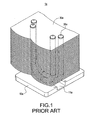
- FIG. 1 is a schematic view showing the conventional combination of heat pipes and heat-dissipating fins.
- the heat sink 1a comprises a heat-conducting base 10a, two U-shaped heat pipes 20a and a plurality of fins 30a.
- the heat-conducting base 10a is provided with a plurality of grooves 11a.
- the two U-shaped heat pipes 20a are inserted into the grooves 11a.
- the heat pipe 20a penetrates through-holes of the plurality of fins 30a. With this arrangement, the heat-conducting base 10a is adhered to a heat-generating element.
- the heat sink 1a can conduct the heat generated by the heat-generating electronic element quickly.
- the heat is conducted from the heat pipe 20a to the fins 30a. Then, the fins 30a dissipate the heat quickly to the outside.
- the heat pipes 20a cannot conduct the heat uniformly throughout the fins 30a, so that the portions away from the heat pipe 10a are poor in heat-dissipating efficiency.
- the heat generated by the electronic elements is increased accordingly.
- the heat-dissipating efficiency of the heat sink also has to be improved. Due to the limited volume of the current electronic product, it is an important issue to increase the heat-dissipating area of the heat sink 1a as large as possible in order to increase the heat-dissipating efficiency.
- the present Inventor proposes a reasonable and novel structure based on his deliberate research and expert experiences.
- the present invention is to provide a fin according to claim 10 and a heat sink of a large area according to claim 12.
- a heat-dissipating body is further provided in a limited space, so that the fins and the heat-dissipating body can dissipate the heat of a heat-generating element. In this way, the heat-dissipating efficiency can be enhanced.
- the present invention is to provide a method for manufacturing a heat sink of a large area according to claim 1.
- the present invention does not need additional space for arranging the fins.
- the heat sink has a plurality of fins, but also a heat-dissipating body can be further disposed in the accommodating holes of the fins.
- the heat sink of the present invention has a larger heat-dissipating area than that in prior art. Since the fins and the heat-dissipating body dissipate the heat of the heat-generating element simultaneously, the heat-dissipating efficiency of the heat sink can be increased. Thus, the practicability of the present invention can be increased.
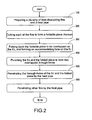
- FIG. 2 is a flow chart showing the method for manufacturing the heat sink of a large area according to the present invention
- FIG. 3 is an assembled view showing the heat sink of a large area according to the present invention.
- a heat pipe 10 a heat-conducting base 20, a heat-dissipating body 30 and a plurality of fins 40 are provided (step 100).
- the heat pipe 10 penetrates the heat-conducting base 20.
- the heat-dissipating body 30 is an aluminum-extruded fin which has a base 31 and a plurality of extending pieces 32 extending upwards from the base 31. The extending pieces 32 are parallel to each other and arranged at intervals. A channel 300 is formed between any two extending pieces 32. Further, the fins 40 are penetrated by the heat pipe 10.
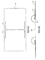
- FIGS. 4A to 4D show the method for manufacturing the fin 40.
- a tool (not shown) is used to cut the fin 40 (step 200) so as to form a plurality of cutting lines 41 on the fin 40.
- the cutting lines 41 form at least one foldable piece 42 on the fin 40.
- the cutting lines 41 forms a U shape
- one foldable piece 42 can be formed on the fin 41.
- both sides of the fin 40 can generate a foldable piece 42 respectively.
- the foldable piece 42 is folded back, so that the folded piece 42 can be overlapped on the fin 40.
- a hollow airflow channel 420 is formed between the folded piece 42 and the fin 40.
- the hollow airflow channel 420 allows airflow to flow through to take away the heat.
- the fin 40 is formed with an accommodating hole 400 (step 300).
- the fin 40 and the folded piece 42 are punched to form two overlapped through-holes 401, 402 (step 400).
- the step 400 is performed after the step 300. That is, in the present embodiment, the fin 40 and the folded piece 42 overlapped on the fin 40 are punched at the same time. Alternatively, the step 400 can be performed before the step 300.
- the fin 40 and the foldable piece 42 are first punched to form two overlapped through-holes 401, 402. Then, the step 300 is performed. The foldable piece 42 is folded back to be overlapped on the fin 40, so that the two through-holes 401, 402 are overlapped. Then, a tool 50 is used to press the peripheries of the two through-holes 401, 421. In this way, the peripheries of the two through-holes 401, 421 are formed with two overlapped flanges 402, 422.
- the two through-holes 401, 422 of the fin 40 and the folded piece 42 are aligned with the heat pipe 10, so that the fin 40 and the folded piece 42 can be penetrated by the heat pipe 10 (step 500).
- the base 31 of the heat-dissipating body 30 is disposed on the top surface of the heat-conducting base 20 and is accommodated in the accommodating hole 400 of the fin 40.
- FIGS. 5 to 7 Please refer to FIGS. 5 to 7 .
- Fig. 5 is a perspective view showing the external appearance of the heat sink of the present invention.
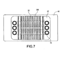
- FIG. 6 and FIG. 7 are cross-sectional views of the present invention respectively.
- other fins can be penetrated by the heat pipe 10 (step 600), thereby completing a heat sink 1.
- the flange 402 of the through-hole 401 of the fin 40 is adhered to an outer wall of the heat pipe 10 tightly (excluding a narrowed section 101 of the heat pipe 10).
- Most of the extending pieces 32 of the heat-dissipating body 30 are accommodated in the accommodating holes 400 of a stack of fins 40.
- the channels 300 of the heat-dissipating body 20 are in communication with each other.
- FIG. 8 is a schematic view showing the operating state of the heat sink of a large area according to the present invention.
- the heat sink 1 When the heat sink 1 is used to dissipate the heat of a heat-generating electronic element 60, the heat-conducting base 20 and the bottom section of the heat pipe 10 are adhered to the surface of the heat-generating electronic element 60.
- the heat generated by the heat-generating electronic element 60 is conducted to the heat-conducting base 20 and the heat pipe 10.
- the heat is further conducted to the fins 40 by means of the heat pipe 10.
- the heat conducted to the heat-conducting base 20 is further conducted to the heat-dissipating body 30.
- the extending pieces 32 dissipate the heat into the channels 300 that are in communication with each other.
- the fins 40 and the heat-dissipating body 30 are used to dissipate the heat of the heat-generating electronic element 60 at the same time to the outside. In this way, the temperature of the heat-generating electronic element 60 can be reduced, and the accumulation of heat on the heat-generating electronic element 60 can be prevented. Thus, the heat-dissipating efficiency of the heat sink 1 is increased.
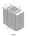
- FIG. 9 is a view showing the heat sink of a large area according to the second embodiment of the present invention.
- the present embodiment is substantially the same as the first embodiment. The difference between the present embodiment and the first embodiment is described as follows.
- the heat sink 1' is not provided with a heat-conducting base.
- the fins 40' are penetrated by a flat heat pipe 10'.
- Each of the fins 40' is provided with two foldable pieces 42' and an accommodating hole 400' is formed between the two foldable pieces 42'.
- a heat-dissipating body 30' is also accommodated in the accommodating hole 400'.
Landscapes
- Engineering & Computer Science (AREA)
- Physics & Mathematics (AREA)
- Condensed Matter Physics & Semiconductors (AREA)
- Power Engineering (AREA)
- Microelectronics & Electronic Packaging (AREA)
- Computer Hardware Design (AREA)
- General Physics & Mathematics (AREA)
- General Engineering & Computer Science (AREA)
- Life Sciences & Earth Sciences (AREA)
- Manufacturing & Machinery (AREA)
- Mechanical Engineering (AREA)
- Thermal Sciences (AREA)
- Sustainable Development (AREA)
- Cooling Or The Like Of Semiconductors Or Solid State Devices (AREA)
- Cooling Or The Like Of Electrical Apparatus (AREA)
Claims (15)
- Verfahren zur Herstellung eines Kühlkörpers (1) für einen großen Bereich, das die Schritte umfasst:a) Bereitstellen mehrerer Rippen (40) und eines Wärmerohres (10); dadurch gekennzeichnet, dass das Verfahren ferner die Schritte umfasst:b) Zuschneiden jeder Rippe (40), um auf jeder Rippe (40) mehrere Schnittlinien (41) auszubilden, wobei die Schnittlinien mindestens ein faltbares Stück (42) bilden;c) Zurückfalten des faltbaren Stücks (42), um auf der Rippe (40) zu überlappen, um dadurch ein aufzunehmendes Loch (400) auf der Rippe (40) zu bilden;d) Stanzen der Rippe (40) und des gefalteten Stücks (42), um zwei überlappende Durchgangslöcher (401, 421) auszubilden;e) Durchdringen der zwei Durchgangslöcher (401, 421) der Rippe (40) und des gefalteten Stücks (42) mit dem Wärmerohr (10); undf) Durchdringen anderer Rippen (40) mit dem Wärmerohr (10) entsprechend dem Schritt e).
- Verfahren zur Herstellung eines Kühlkörpers für einen großen Bereich nach Anspruch 1, wobei in dem Schritt b) die Schnittlinien (41) eine U-Form auf jeder der Rippen (40) bilden, um ein faltbares Stück (42) auf der Rippe (40) auszubilden.
- Verfahren zur Herstellung eines Kühlkörpers für einen großen Bereich nach Anspruch 1, wobei in dem Schritt b) die Schnittlinien (41) eine H-Form auf jeder der Rippen (40) bilden, um zwei faltbare Stücke (42) auf der Rippe (40) auszubilden.
- Verfahren zur Herstellung eines Kühlkörpers für einen großen Bereich nach Anspruch 1, wobei im Schritt c) zwischen dem gefalteten Stück (42) und der Rippe (40) ein hohler Luftströmungskanal (420) ausgebildet wird.
- Verfahren zur Herstellung eines Kühlkörpers für einen großen Bereich nach Anspruch 1, wobei der Schritt d) nach dem Schritt c) durchgeführt wird, das faltbare Stück (42) zurückgefaltet wird, um in dem Schritt c) auf der Rippe (40) zu überlappen, und wobei die Rippe (40) und das gefaltete Stück (42), die auf der Rippe (40) überlappen, im Schritt d) gestanzt werden.
- Verfahren zur Herstellung eines Kühlkörpers für einen großen Bereich nach Anspruch 1, wobei der Schritt d) vor dem Schritt c) durchgeführt wird, die Rippe (40) und das faltbare Stück (42) im Schritt d) gestanzt werden, um zwei überlappende Durchgangslöcher (401, 421) auszubilden, wobei das faltbare Stück (42) zurückgefaltet wird, um in dem Schritt c) auf der Rippe (40) zu überlappen, wodurch die zwei Durchgangslöcher (401, 421) überlappen.
- Verfahren zur Herstellung eines Kühlkörpers für einen großen Bereich nach Anspruch 1, das ferner zwischen dem Schritt d) und dem Schritt e) einen Schritt d') des Pressens von Begrenzungsflächen der zwei Durchgangslöcher (401, 421) umfasst, um zwei überlappende Flansche (402, 422) auf den Begrenzungsflächen der zwei Durchgangslöcher (401, 421) auszubilden, wobei der Flansch (402) des Durchgangsloches (401) der Rippe (40) in dem Schritt f) an einer äußeren Wand des Wärmerohres (10) durch Haften befestigt wird.
- Verfahren zur Herstellung eines Kühlkörpers für einen großen Bereich nach Anspruch 1, das ferner einen Schritt g) des Vorsehens eines wärmeabführenden Körpers (30) umfasst, wobei der wärmeabführende Körper (30) in dem aufnehmenden Loch (400) der Rippe (40) untergebracht ist.
- Verfahren zur Herstellung eines Kühlkörpers für einen großen Bereich nach Anspruch 1, das ferner einen Schritt h) zum Bereitstellen einer wärmeleitenden Basis (20) umfasst, wobei das Wärmerohr (10) in die wärmeleitende Basis (20) eingesetzt wird.
- Wärmeabführende Rippe (40), dadurch gekennzeichnet, dass die Rippe mit einem faltbaren Stück (42) versehen ist, wobei das faltbare Stück (42) zurückgefaltet ist, um auf der Rippe (40) überlappt zu sein, und dadurch gekennzeichnet, dass die Rippe mit einem aufnehmenden Loch (400) ausgebildet ist; wobei das faltbare Stück (42) und die Rippe (40) mit zwei Durchgangslöchern (401, 421) versehen sind, wobei die Begrenzungsflächen der zwei Durchgangslöcher (401, 421) mit zwei überlappten Flanschen (402, 422) versehen sind.
- Wärmeabführende Rippe nach Anspruch 10, wobei zwischen dem gefalteten Stück (42) und der Rippe (40) ein hohler Luftströmungskanal (420) ausgebildet ist.
- Kühlkörper für einen großen Bereich, der umfasst:ein Wärmerohr (10); undmehrere Rippen (40), die parallel zueinander sind und in Intervallen angeordnet sind, wobei das Wärmerohr (10) die Rippen (40) durchdringt, wobei die Rippe (40) wie in Anspruch 10 beschaffen ist und das Wärmerohr (10) die zwei Durchgangslöcher (401, 421) der Rippe (40) durchdringt.
- Kühlkörper für einen großen Bereich nach Anspruch 12, wobei der Flansch (402) der Rippe (40) an einer äußeren Wand des Wärmerohres (10) durch Haften befestigt ist.
- Kühlkörper für einen großen Bereich nach Anspruch 12, wobei zwischen dem gefalteten Stück (42) und der Rippe (40) ein hohler Luftströmungskanal (420) ausgebildet ist.
- Kühlkörper für einen großen Bereich nach Anspruch 12, der ferner einen wärmeabführenden Körper (30) und eine wärmeleitende Basis (20) umfasst, wobei der wärmeabführende Körper (30) in den aufnehmenden Löchern (400) der Rippen (40) angeordnet ist, wobei die wärmeleitende Basis (20) ermöglicht, dass das Wärmerohr (10) in sie eingesetzt werden kann.
Priority Applications (1)
| Application Number | Priority Date | Filing Date | Title |
|---|---|---|---|
| EP09009941.7A EP2280236B1 (de) | 2009-07-31 | 2009-07-31 | Wärmeableitende Rippen, Kühlkörper für einen großen Bereich mit den wärmeableitenden Rippen und Herstellungsverfahren dafür |
Applications Claiming Priority (1)
| Application Number | Priority Date | Filing Date | Title |
|---|---|---|---|
| EP09009941.7A EP2280236B1 (de) | 2009-07-31 | 2009-07-31 | Wärmeableitende Rippen, Kühlkörper für einen großen Bereich mit den wärmeableitenden Rippen und Herstellungsverfahren dafür |
Publications (2)
| Publication Number | Publication Date |
|---|---|
| EP2280236A1 EP2280236A1 (de) | 2011-02-02 |
| EP2280236B1 true EP2280236B1 (de) | 2013-05-01 |
Family
ID=41351725
Family Applications (1)
| Application Number | Title | Priority Date | Filing Date |
|---|---|---|---|
| EP09009941.7A Not-in-force EP2280236B1 (de) | 2009-07-31 | 2009-07-31 | Wärmeableitende Rippen, Kühlkörper für einen großen Bereich mit den wärmeableitenden Rippen und Herstellungsverfahren dafür |
Country Status (1)
| Country | Link |
|---|---|
| EP (1) | EP2280236B1 (de) |
Families Citing this family (2)
| Publication number | Priority date | Publication date | Assignee | Title |
|---|---|---|---|---|
| CN110679207B (zh) * | 2017-05-25 | 2021-06-29 | 罗伯特·博世有限公司 | 冷却装置 |
| CN111811032A (zh) * | 2020-07-24 | 2020-10-23 | 珠海格力电器股份有限公司 | 散热件、汀片及取暖器 |
Family Cites Families (3)
| Publication number | Priority date | Publication date | Assignee | Title |
|---|---|---|---|---|
| US20070261244A1 (en) * | 2006-05-12 | 2007-11-15 | Chih-Hung Cheng | Leveling Method for Embedding Heat Pipe in Heat-Conducting Seat |
| CN200973220Y (zh) * | 2006-11-10 | 2007-11-07 | 鈤新科技股份有限公司 | 固定座及固定座与热管的组合结构 |
| US7661466B2 (en) * | 2007-04-18 | 2010-02-16 | Fu Zhun Precision Industry (Shen Zhen) Co., Ltd. | Heat sink assembly having a fin also functioning as a supporting bracket |
-
2009
- 2009-07-31 EP EP09009941.7A patent/EP2280236B1/de not_active Not-in-force
Also Published As
| Publication number | Publication date |
|---|---|
| EP2280236A1 (de) | 2011-02-02 |
Similar Documents
| Publication | Publication Date | Title |
|---|---|---|
| US8375584B2 (en) | Method for manufacturing large-area heat sink having heat-dissipating fins | |
| EP1172852B1 (de) | Gewölbter Matrixkühlkörper zum Kühlen von elektronischen Bauteilen | |
| US7312996B2 (en) | Heat sink for memory strips | |
| US20100006268A1 (en) | Vapor chamber and supporting structure of the same | |
| CN100386872C (zh) | 液冷系统 | |
| US6607028B1 (en) | Positioning structure for heat dissipating fins | |
| US20040187307A1 (en) | Heat sink | |
| US8459335B2 (en) | Heat sink having heat-dissipating fins of large area and method for manufacturing the same | |
| US8297341B2 (en) | Heat dissipating structure and method of forming the same | |
| US7204303B2 (en) | Flat tube cold plate assembly | |
| JP6775374B2 (ja) | 放熱ユニットの製造方法 | |
| EP2280236B1 (de) | Wärmeableitende Rippen, Kühlkörper für einen großen Bereich mit den wärmeableitenden Rippen und Herstellungsverfahren dafür | |
| US9909815B2 (en) | Assembling structure of heat dissipation device | |
| US20100188809A1 (en) | Radiator For Computer Memory | |
| EP2280237A1 (de) | Kühlkörper mit wärmeableitenden Rippen für einen großen Bereich und Herstellungsverfahren dafür | |
| KR100882581B1 (ko) | 컴퓨터 부품용 냉각장치 및 그 제조방법 | |
| US9250026B2 (en) | Heat exchanger and method for fabricating the same | |
| JP4485013B2 (ja) | プレート型ヒートパイプ及びその製造方法 | |
| CN101943530B (zh) | 散热鳍片及其制法及具有该鳍片的散热器及其制法 | |
| JP5601257B2 (ja) | プレート型冷却器の製造方法 | |
| EP2284885B1 (de) | Wärmeableitende Rippe zur Erhöhung des wärmeableitenden Bereichs, Kühlkörper mit der wärmeableitenden Rippe und Herstellungsverfahren dafür | |
| JP5856750B2 (ja) | 放熱装置 | |
| US20120227948A1 (en) | Heat sink fin structure | |
| JP3786868B2 (ja) | ヒートシンクおよびヒートシンクの製造方法 | |
| TWI401406B (zh) | 散熱鰭片及其製造方法及具有該散熱鰭片之大面積散熱器及其製造方法 |
Legal Events
| Date | Code | Title | Description |
|---|---|---|---|
| PUAI | Public reference made under article 153(3) epc to a published international application that has entered the european phase |
Free format text: ORIGINAL CODE: 0009012 |
|
| 17P | Request for examination filed |
Effective date: 20100215 |
|
| AK | Designated contracting states |
Kind code of ref document: A1 Designated state(s): AT BE BG CH CY CZ DE DK EE ES FI FR GB GR HR HU IE IS IT LI LT LU LV MC MK MT NL NO PL PT RO SE SI SK SM TR |
|
| AX | Request for extension of the european patent |
Extension state: AL BA RS |
|
| GRAP | Despatch of communication of intention to grant a patent |
Free format text: ORIGINAL CODE: EPIDOSNIGR1 |
|
| GRAS | Grant fee paid |
Free format text: ORIGINAL CODE: EPIDOSNIGR3 |
|
| GRAA | (expected) grant |
Free format text: ORIGINAL CODE: 0009210 |
|
| AK | Designated contracting states |
Kind code of ref document: B1 Designated state(s): AT BE BG CH CY CZ DE DK EE ES FI FR GB GR HR HU IE IS IT LI LT LU LV MC MK MT NL NO PL PT RO SE SI SK SM TR |
|
| REG | Reference to a national code |
Ref country code: GB Ref legal event code: FG4D |
|
| REG | Reference to a national code |
Ref country code: AT Ref legal event code: REF Ref document number: 610196 Country of ref document: AT Kind code of ref document: T Effective date: 20130515 Ref country code: CH Ref legal event code: EP |
|
| REG | Reference to a national code |
Ref country code: IE Ref legal event code: FG4D |
|
| REG | Reference to a national code |
Ref country code: DE Ref legal event code: R096 Ref document number: 602009015347 Country of ref document: DE Effective date: 20130627 |
|
| REG | Reference to a national code |
Ref country code: AT Ref legal event code: MK05 Ref document number: 610196 Country of ref document: AT Kind code of ref document: T Effective date: 20130501 |
|
| REG | Reference to a national code |
Ref country code: NL Ref legal event code: VDEP Effective date: 20130501 |
|
| REG | Reference to a national code |
Ref country code: LT Ref legal event code: MG4D |
|
| PG25 | Lapsed in a contracting state [announced via postgrant information from national office to epo] |
Ref country code: SE Free format text: LAPSE BECAUSE OF FAILURE TO SUBMIT A TRANSLATION OF THE DESCRIPTION OR TO PAY THE FEE WITHIN THE PRESCRIBED TIME-LIMIT Effective date: 20130501 Ref country code: FI Free format text: LAPSE BECAUSE OF FAILURE TO SUBMIT A TRANSLATION OF THE DESCRIPTION OR TO PAY THE FEE WITHIN THE PRESCRIBED TIME-LIMIT Effective date: 20130501 Ref country code: LT Free format text: LAPSE BECAUSE OF FAILURE TO SUBMIT A TRANSLATION OF THE DESCRIPTION OR TO PAY THE FEE WITHIN THE PRESCRIBED TIME-LIMIT Effective date: 20130501 Ref country code: SI Free format text: LAPSE BECAUSE OF FAILURE TO SUBMIT A TRANSLATION OF THE DESCRIPTION OR TO PAY THE FEE WITHIN THE PRESCRIBED TIME-LIMIT Effective date: 20130501 Ref country code: NO Free format text: LAPSE BECAUSE OF FAILURE TO SUBMIT A TRANSLATION OF THE DESCRIPTION OR TO PAY THE FEE WITHIN THE PRESCRIBED TIME-LIMIT Effective date: 20130801 Ref country code: ES Free format text: LAPSE BECAUSE OF FAILURE TO SUBMIT A TRANSLATION OF THE DESCRIPTION OR TO PAY THE FEE WITHIN THE PRESCRIBED TIME-LIMIT Effective date: 20130812 Ref country code: AT Free format text: LAPSE BECAUSE OF FAILURE TO SUBMIT A TRANSLATION OF THE DESCRIPTION OR TO PAY THE FEE WITHIN THE PRESCRIBED TIME-LIMIT Effective date: 20130501 Ref country code: GR Free format text: LAPSE BECAUSE OF FAILURE TO SUBMIT A TRANSLATION OF THE DESCRIPTION OR TO PAY THE FEE WITHIN THE PRESCRIBED TIME-LIMIT Effective date: 20130802 Ref country code: PT Free format text: LAPSE BECAUSE OF FAILURE TO SUBMIT A TRANSLATION OF THE DESCRIPTION OR TO PAY THE FEE WITHIN THE PRESCRIBED TIME-LIMIT Effective date: 20130902 Ref country code: IS Free format text: LAPSE BECAUSE OF FAILURE TO SUBMIT A TRANSLATION OF THE DESCRIPTION OR TO PAY THE FEE WITHIN THE PRESCRIBED TIME-LIMIT Effective date: 20130901 |
|
| PG25 | Lapsed in a contracting state [announced via postgrant information from national office to epo] |
Ref country code: PL Free format text: LAPSE BECAUSE OF FAILURE TO SUBMIT A TRANSLATION OF THE DESCRIPTION OR TO PAY THE FEE WITHIN THE PRESCRIBED TIME-LIMIT Effective date: 20130501 Ref country code: BG Free format text: LAPSE BECAUSE OF FAILURE TO SUBMIT A TRANSLATION OF THE DESCRIPTION OR TO PAY THE FEE WITHIN THE PRESCRIBED TIME-LIMIT Effective date: 20130801 Ref country code: HR Free format text: LAPSE BECAUSE OF FAILURE TO SUBMIT A TRANSLATION OF THE DESCRIPTION OR TO PAY THE FEE WITHIN THE PRESCRIBED TIME-LIMIT Effective date: 20130501 Ref country code: CY Free format text: LAPSE BECAUSE OF FAILURE TO SUBMIT A TRANSLATION OF THE DESCRIPTION OR TO PAY THE FEE WITHIN THE PRESCRIBED TIME-LIMIT Effective date: 20130501 |
|
| PG25 | Lapsed in a contracting state [announced via postgrant information from national office to epo] |
Ref country code: LV Free format text: LAPSE BECAUSE OF FAILURE TO SUBMIT A TRANSLATION OF THE DESCRIPTION OR TO PAY THE FEE WITHIN THE PRESCRIBED TIME-LIMIT Effective date: 20130501 |
|
| PG25 | Lapsed in a contracting state [announced via postgrant information from national office to epo] |
Ref country code: CZ Free format text: LAPSE BECAUSE OF FAILURE TO SUBMIT A TRANSLATION OF THE DESCRIPTION OR TO PAY THE FEE WITHIN THE PRESCRIBED TIME-LIMIT Effective date: 20130501 Ref country code: EE Free format text: LAPSE BECAUSE OF FAILURE TO SUBMIT A TRANSLATION OF THE DESCRIPTION OR TO PAY THE FEE WITHIN THE PRESCRIBED TIME-LIMIT Effective date: 20130501 Ref country code: BE Free format text: LAPSE BECAUSE OF FAILURE TO SUBMIT A TRANSLATION OF THE DESCRIPTION OR TO PAY THE FEE WITHIN THE PRESCRIBED TIME-LIMIT Effective date: 20130501 Ref country code: SK Free format text: LAPSE BECAUSE OF FAILURE TO SUBMIT A TRANSLATION OF THE DESCRIPTION OR TO PAY THE FEE WITHIN THE PRESCRIBED TIME-LIMIT Effective date: 20130501 Ref country code: DK Free format text: LAPSE BECAUSE OF FAILURE TO SUBMIT A TRANSLATION OF THE DESCRIPTION OR TO PAY THE FEE WITHIN THE PRESCRIBED TIME-LIMIT Effective date: 20130501 |
|
| PG25 | Lapsed in a contracting state [announced via postgrant information from national office to epo] |
Ref country code: RO Free format text: LAPSE BECAUSE OF FAILURE TO SUBMIT A TRANSLATION OF THE DESCRIPTION OR TO PAY THE FEE WITHIN THE PRESCRIBED TIME-LIMIT Effective date: 20130501 Ref country code: IT Free format text: LAPSE BECAUSE OF FAILURE TO SUBMIT A TRANSLATION OF THE DESCRIPTION OR TO PAY THE FEE WITHIN THE PRESCRIBED TIME-LIMIT Effective date: 20130501 Ref country code: NL Free format text: LAPSE BECAUSE OF FAILURE TO SUBMIT A TRANSLATION OF THE DESCRIPTION OR TO PAY THE FEE WITHIN THE PRESCRIBED TIME-LIMIT Effective date: 20130501 Ref country code: MC Free format text: LAPSE BECAUSE OF FAILURE TO SUBMIT A TRANSLATION OF THE DESCRIPTION OR TO PAY THE FEE WITHIN THE PRESCRIBED TIME-LIMIT Effective date: 20130501 |
|
| REG | Reference to a national code |
Ref country code: CH Ref legal event code: PL |
|
| PLBE | No opposition filed within time limit |
Free format text: ORIGINAL CODE: 0009261 |
|
| STAA | Information on the status of an ep patent application or granted ep patent |
Free format text: STATUS: NO OPPOSITION FILED WITHIN TIME LIMIT |
|
| 26N | No opposition filed |
Effective date: 20140204 |
|
| REG | Reference to a national code |
Ref country code: IE Ref legal event code: MM4A |
|
| PG25 | Lapsed in a contracting state [announced via postgrant information from national office to epo] |
Ref country code: CH Free format text: LAPSE BECAUSE OF NON-PAYMENT OF DUE FEES Effective date: 20130731 Ref country code: LI Free format text: LAPSE BECAUSE OF NON-PAYMENT OF DUE FEES Effective date: 20130731 |
|
| REG | Reference to a national code |
Ref country code: DE Ref legal event code: R097 Ref document number: 602009015347 Country of ref document: DE Effective date: 20140204 |
|
| PG25 | Lapsed in a contracting state [announced via postgrant information from national office to epo] |
Ref country code: IE Free format text: LAPSE BECAUSE OF NON-PAYMENT OF DUE FEES Effective date: 20130731 |
|
| PGFP | Annual fee paid to national office [announced via postgrant information from national office to epo] |
Ref country code: DE Payment date: 20140724 Year of fee payment: 6 |
|
| PGFP | Annual fee paid to national office [announced via postgrant information from national office to epo] |
Ref country code: GB Payment date: 20140730 Year of fee payment: 6 Ref country code: FR Payment date: 20140708 Year of fee payment: 6 |
|
| PG25 | Lapsed in a contracting state [announced via postgrant information from national office to epo] |
Ref country code: SM Free format text: LAPSE BECAUSE OF FAILURE TO SUBMIT A TRANSLATION OF THE DESCRIPTION OR TO PAY THE FEE WITHIN THE PRESCRIBED TIME-LIMIT Effective date: 20130501 |
|
| PG25 | Lapsed in a contracting state [announced via postgrant information from national office to epo] |
Ref country code: TR Free format text: LAPSE BECAUSE OF FAILURE TO SUBMIT A TRANSLATION OF THE DESCRIPTION OR TO PAY THE FEE WITHIN THE PRESCRIBED TIME-LIMIT Effective date: 20130501 Ref country code: MT Free format text: LAPSE BECAUSE OF FAILURE TO SUBMIT A TRANSLATION OF THE DESCRIPTION OR TO PAY THE FEE WITHIN THE PRESCRIBED TIME-LIMIT Effective date: 20130501 |
|
| PG25 | Lapsed in a contracting state [announced via postgrant information from national office to epo] |
Ref country code: MK Free format text: LAPSE BECAUSE OF FAILURE TO SUBMIT A TRANSLATION OF THE DESCRIPTION OR TO PAY THE FEE WITHIN THE PRESCRIBED TIME-LIMIT Effective date: 20130501 Ref country code: LU Free format text: LAPSE BECAUSE OF NON-PAYMENT OF DUE FEES Effective date: 20130731 Ref country code: HU Free format text: LAPSE BECAUSE OF FAILURE TO SUBMIT A TRANSLATION OF THE DESCRIPTION OR TO PAY THE FEE WITHIN THE PRESCRIBED TIME-LIMIT; INVALID AB INITIO Effective date: 20090731 |
|
| REG | Reference to a national code |
Ref country code: DE Ref legal event code: R119 Ref document number: 602009015347 Country of ref document: DE |
|
| GBPC | Gb: european patent ceased through non-payment of renewal fee |
Effective date: 20150731 |
|
| PG25 | Lapsed in a contracting state [announced via postgrant information from national office to epo] |
Ref country code: DE Free format text: LAPSE BECAUSE OF NON-PAYMENT OF DUE FEES Effective date: 20160202 Ref country code: GB Free format text: LAPSE BECAUSE OF NON-PAYMENT OF DUE FEES Effective date: 20150731 |
|
| REG | Reference to a national code |
Ref country code: FR Ref legal event code: ST Effective date: 20160331 |
|
| PG25 | Lapsed in a contracting state [announced via postgrant information from national office to epo] |
Ref country code: FR Free format text: LAPSE BECAUSE OF NON-PAYMENT OF DUE FEES Effective date: 20150731 |