EP2279446B1 - Elektrisch stimulierbares volumenhologramm - Google Patents
Elektrisch stimulierbares volumenhologramm Download PDFInfo
- Publication number
- EP2279446B1 EP2279446B1 EP09734333.9A EP09734333A EP2279446B1 EP 2279446 B1 EP2279446 B1 EP 2279446B1 EP 09734333 A EP09734333 A EP 09734333A EP 2279446 B1 EP2279446 B1 EP 2279446B1
- Authority
- EP
- European Patent Office
- Prior art keywords
- electrodes
- recording material
- security element
- electrode
- elastic element
- Prior art date
- Legal status (The legal status is an assumption and is not a legal conclusion. Google has not performed a legal analysis and makes no representation as to the accuracy of the status listed.)
- Active
Links
- 239000000463 material Substances 0.000 claims description 123
- 238000000034 method Methods 0.000 claims description 16
- 238000004519 manufacturing process Methods 0.000 claims description 9
- 238000003860 storage Methods 0.000 claims description 4
- 238000007373 indentation Methods 0.000 claims description 2
- 238000012986 modification Methods 0.000 claims 2
- 230000004048 modification Effects 0.000 claims 2
- 230000008859 change Effects 0.000 description 14
- 230000003287 optical effect Effects 0.000 description 10
- 239000000758 substrate Substances 0.000 description 8
- 229920001971 elastomer Polymers 0.000 description 6
- 239000000806 elastomer Substances 0.000 description 6
- 239000002800 charge carrier Substances 0.000 description 5
- 238000007639 printing Methods 0.000 description 5
- 230000008569 process Effects 0.000 description 5
- -1 silver halide Chemical class 0.000 description 5
- 230000000694 effects Effects 0.000 description 4
- 230000005284 excitation Effects 0.000 description 4
- SKRWFPLZQAAQSU-UHFFFAOYSA-N stibanylidynetin;hydrate Chemical compound O.[Sn].[Sb] SKRWFPLZQAAQSU-UHFFFAOYSA-N 0.000 description 4
- 230000005540 biological transmission Effects 0.000 description 3
- AMGQUBHHOARCQH-UHFFFAOYSA-N indium;oxotin Chemical compound [In].[Sn]=O AMGQUBHHOARCQH-UHFFFAOYSA-N 0.000 description 3
- 239000004973 liquid crystal related substance Substances 0.000 description 3
- 229910052751 metal Inorganic materials 0.000 description 3
- 239000002184 metal Substances 0.000 description 3
- 238000004528 spin coating Methods 0.000 description 3
- XLOMVQKBTHCTTD-UHFFFAOYSA-N zinc oxide Inorganic materials [Zn]=O XLOMVQKBTHCTTD-UHFFFAOYSA-N 0.000 description 3
- KAKZBPTYRLMSJV-UHFFFAOYSA-N Butadiene Chemical compound C=CC=C KAKZBPTYRLMSJV-UHFFFAOYSA-N 0.000 description 2
- RRHGJUQNOFWUDK-UHFFFAOYSA-N Isoprene Chemical compound CC(=C)C=C RRHGJUQNOFWUDK-UHFFFAOYSA-N 0.000 description 2
- 229920001609 Poly(3,4-ethylenedioxythiophene) Polymers 0.000 description 2
- 229910006404 SnO 2 Inorganic materials 0.000 description 2
- 230000009471 action Effects 0.000 description 2
- 239000000853 adhesive Substances 0.000 description 2
- 230000001427 coherent effect Effects 0.000 description 2
- 238000013461 design Methods 0.000 description 2
- 238000007646 gravure printing Methods 0.000 description 2
- 238000005286 illumination Methods 0.000 description 2
- 238000007641 inkjet printing Methods 0.000 description 2
- 230000002452 interceptive effect Effects 0.000 description 2
- 238000000608 laser ablation Methods 0.000 description 2
- 239000011159 matrix material Substances 0.000 description 2
- 229910044991 metal oxide Inorganic materials 0.000 description 2
- 150000004706 metal oxides Chemical class 0.000 description 2
- 238000007645 offset printing Methods 0.000 description 2
- 239000011368 organic material Substances 0.000 description 2
- 238000000206 photolithography Methods 0.000 description 2
- 238000007650 screen-printing Methods 0.000 description 2
- 230000003595 spectral effect Effects 0.000 description 2
- 238000004544 sputter deposition Methods 0.000 description 2
- PRAKJMSDJKAYCZ-UHFFFAOYSA-N squalane Chemical compound CC(C)CCCC(C)CCCC(C)CCCCC(C)CCCC(C)CCCC(C)C PRAKJMSDJKAYCZ-UHFFFAOYSA-N 0.000 description 2
- 230000000007 visual effect Effects 0.000 description 2
- YVTHLONGBIQYBO-UHFFFAOYSA-N zinc indium(3+) oxygen(2-) Chemical compound [O--].[Zn++].[In+3] YVTHLONGBIQYBO-UHFFFAOYSA-N 0.000 description 2
- 239000011787 zinc oxide Substances 0.000 description 2
- NLHHRLWOUZZQLW-UHFFFAOYSA-N Acrylonitrile Chemical compound C=CC#N NLHHRLWOUZZQLW-UHFFFAOYSA-N 0.000 description 1
- 108010010803 Gelatin Proteins 0.000 description 1
- 239000005062 Polybutadiene Substances 0.000 description 1
- 229920002367 Polyisobutene Polymers 0.000 description 1
- 239000004983 Polymer Dispersed Liquid Crystal Substances 0.000 description 1
- 239000004793 Polystyrene Substances 0.000 description 1
- 230000001070 adhesive effect Effects 0.000 description 1
- 230000002411 adverse Effects 0.000 description 1
- 238000013459 approach Methods 0.000 description 1
- 238000007630 basic procedure Methods 0.000 description 1
- 229920001400 block copolymer Polymers 0.000 description 1
- 239000003086 colorant Substances 0.000 description 1
- 238000011161 development Methods 0.000 description 1
- 239000004205 dimethyl polysiloxane Substances 0.000 description 1
- KPUWHANPEXNPJT-UHFFFAOYSA-N disiloxane Chemical class [SiH3]O[SiH3] KPUWHANPEXNPJT-UHFFFAOYSA-N 0.000 description 1
- 239000013013 elastic material Substances 0.000 description 1
- 230000005684 electric field Effects 0.000 description 1
- 239000007772 electrode material Substances 0.000 description 1
- 238000005516 engineering process Methods 0.000 description 1
- ZINJLDJMHCUBIP-UHFFFAOYSA-N ethametsulfuron-methyl Chemical compound CCOC1=NC(NC)=NC(NC(=O)NS(=O)(=O)C=2C(=CC=CC=2)C(=O)OC)=N1 ZINJLDJMHCUBIP-UHFFFAOYSA-N 0.000 description 1
- 229920001973 fluoroelastomer Polymers 0.000 description 1
- 239000011888 foil Substances 0.000 description 1
- 230000006870 function Effects 0.000 description 1
- 229920000159 gelatin Polymers 0.000 description 1
- 239000008273 gelatin Substances 0.000 description 1
- 235000019322 gelatine Nutrition 0.000 description 1
- 235000011852 gelatine desserts Nutrition 0.000 description 1
- 238000001093 holography Methods 0.000 description 1
- 230000002427 irreversible effect Effects 0.000 description 1
- 238000003475 lamination Methods 0.000 description 1
- 239000007788 liquid Substances 0.000 description 1
- 150000002739 metals Chemical class 0.000 description 1
- JXTPJDDICSTXJX-UHFFFAOYSA-N n-Triacontane Natural products CCCCCCCCCCCCCCCCCCCCCCCCCCCCCC JXTPJDDICSTXJX-UHFFFAOYSA-N 0.000 description 1
- 230000001151 other effect Effects 0.000 description 1
- 239000002245 particle Substances 0.000 description 1
- 239000004033 plastic Substances 0.000 description 1
- 229920003023 plastic Polymers 0.000 description 1
- 239000004014 plasticizer Substances 0.000 description 1
- 229920000435 poly(dimethylsiloxane) Polymers 0.000 description 1
- 229920002857 polybutadiene Polymers 0.000 description 1
- 229920001195 polyisoprene Polymers 0.000 description 1
- 229920002223 polystyrene Polymers 0.000 description 1
- 229920002635 polyurethane Polymers 0.000 description 1
- 239000004814 polyurethane Substances 0.000 description 1
- 230000001681 protective effect Effects 0.000 description 1
- 230000002829 reductive effect Effects 0.000 description 1
- 230000002441 reversible effect Effects 0.000 description 1
- 238000007493 shaping process Methods 0.000 description 1
- 229910052710 silicon Inorganic materials 0.000 description 1
- 239000010703 silicon Substances 0.000 description 1
- 229910052709 silver Inorganic materials 0.000 description 1
- 239000004332 silver Substances 0.000 description 1
- 229940032094 squalane Drugs 0.000 description 1
- 230000000638 stimulation Effects 0.000 description 1
- 230000001960 triggered effect Effects 0.000 description 1
- 238000007738 vacuum evaporation Methods 0.000 description 1
- 238000007740 vapor deposition Methods 0.000 description 1
- 238000012795 verification Methods 0.000 description 1
- XLYOFNOQVPJJNP-UHFFFAOYSA-N water Substances O XLYOFNOQVPJJNP-UHFFFAOYSA-N 0.000 description 1
Images

Classifications
-
- B—PERFORMING OPERATIONS; TRANSPORTING
- B42—BOOKBINDING; ALBUMS; FILES; SPECIAL PRINTED MATTER
- B42D—BOOKS; BOOK COVERS; LOOSE LEAVES; PRINTED MATTER CHARACTERISED BY IDENTIFICATION OR SECURITY FEATURES; PRINTED MATTER OF SPECIAL FORMAT OR STYLE NOT OTHERWISE PROVIDED FOR; DEVICES FOR USE THEREWITH AND NOT OTHERWISE PROVIDED FOR; MOVABLE-STRIP WRITING OR READING APPARATUS
- B42D25/00—Information-bearing cards or sheet-like structures characterised by identification or security features; Manufacture thereof
- B42D25/30—Identification or security features, e.g. for preventing forgery
- B42D25/328—Diffraction gratings; Holograms
-
- G—PHYSICS
- G02—OPTICS
- G02F—OPTICAL DEVICES OR ARRANGEMENTS FOR THE CONTROL OF LIGHT BY MODIFICATION OF THE OPTICAL PROPERTIES OF THE MEDIA OF THE ELEMENTS INVOLVED THEREIN; NON-LINEAR OPTICS; FREQUENCY-CHANGING OF LIGHT; OPTICAL LOGIC ELEMENTS; OPTICAL ANALOGUE/DIGITAL CONVERTERS
- G02F1/00—Devices or arrangements for the control of the intensity, colour, phase, polarisation or direction of light arriving from an independent light source, e.g. switching, gating or modulating; Non-linear optics
- G02F1/01—Devices or arrangements for the control of the intensity, colour, phase, polarisation or direction of light arriving from an independent light source, e.g. switching, gating or modulating; Non-linear optics for the control of the intensity, phase, polarisation or colour
- G02F1/0128—Devices or arrangements for the control of the intensity, colour, phase, polarisation or direction of light arriving from an independent light source, e.g. switching, gating or modulating; Non-linear optics for the control of the intensity, phase, polarisation or colour based on electro-mechanical, magneto-mechanical, elasto-optic effects
-
- G—PHYSICS
- G03—PHOTOGRAPHY; CINEMATOGRAPHY; ANALOGOUS TECHNIQUES USING WAVES OTHER THAN OPTICAL WAVES; ELECTROGRAPHY; HOLOGRAPHY
- G03H—HOLOGRAPHIC PROCESSES OR APPARATUS
- G03H1/00—Holographic processes or apparatus using light, infrared or ultraviolet waves for obtaining holograms or for obtaining an image from them; Details peculiar thereto
- G03H1/0005—Adaptation of holography to specific applications
- G03H1/0011—Adaptation of holography to specific applications for security or authentication
-
- G—PHYSICS
- G03—PHOTOGRAPHY; CINEMATOGRAPHY; ANALOGOUS TECHNIQUES USING WAVES OTHER THAN OPTICAL WAVES; ELECTROGRAPHY; HOLOGRAPHY
- G03H—HOLOGRAPHIC PROCESSES OR APPARATUS
- G03H1/00—Holographic processes or apparatus using light, infrared or ultraviolet waves for obtaining holograms or for obtaining an image from them; Details peculiar thereto
- G03H1/02—Details of features involved during the holographic process; Replication of holograms without interference recording
- G03H1/0252—Laminate comprising a hologram layer
- G03H1/0256—Laminate comprising a hologram layer having specific functional layer
-
- G—PHYSICS
- G03—PHOTOGRAPHY; CINEMATOGRAPHY; ANALOGOUS TECHNIQUES USING WAVES OTHER THAN OPTICAL WAVES; ELECTROGRAPHY; HOLOGRAPHY
- G03H—HOLOGRAPHIC PROCESSES OR APPARATUS
- G03H1/00—Holographic processes or apparatus using light, infrared or ultraviolet waves for obtaining holograms or for obtaining an image from them; Details peculiar thereto
- G03H1/22—Processes or apparatus for obtaining an optical image from holograms
-
- B42D2033/46—
-
- G—PHYSICS
- G03—PHOTOGRAPHY; CINEMATOGRAPHY; ANALOGOUS TECHNIQUES USING WAVES OTHER THAN OPTICAL WAVES; ELECTROGRAPHY; HOLOGRAPHY
- G03H—HOLOGRAPHIC PROCESSES OR APPARATUS
- G03H1/00—Holographic processes or apparatus using light, infrared or ultraviolet waves for obtaining holograms or for obtaining an image from them; Details peculiar thereto
- G03H1/02—Details of features involved during the holographic process; Replication of holograms without interference recording
- G03H1/024—Hologram nature or properties
- G03H1/0248—Volume holograms
-
- G—PHYSICS
- G03—PHOTOGRAPHY; CINEMATOGRAPHY; ANALOGOUS TECHNIQUES USING WAVES OTHER THAN OPTICAL WAVES; ELECTROGRAPHY; HOLOGRAPHY
- G03H—HOLOGRAPHIC PROCESSES OR APPARATUS
- G03H1/00—Holographic processes or apparatus using light, infrared or ultraviolet waves for obtaining holograms or for obtaining an image from them; Details peculiar thereto
- G03H1/0005—Adaptation of holography to specific applications
- G03H1/0011—Adaptation of holography to specific applications for security or authentication
- G03H2001/0016—Covert holograms or holobjects requiring additional knowledge to be perceived, e.g. holobject reconstructed only under IR illumination
-
- G—PHYSICS
- G03—PHOTOGRAPHY; CINEMATOGRAPHY; ANALOGOUS TECHNIQUES USING WAVES OTHER THAN OPTICAL WAVES; ELECTROGRAPHY; HOLOGRAPHY
- G03H—HOLOGRAPHIC PROCESSES OR APPARATUS
- G03H1/00—Holographic processes or apparatus using light, infrared or ultraviolet waves for obtaining holograms or for obtaining an image from them; Details peculiar thereto
- G03H1/04—Processes or apparatus for producing holograms
- G03H1/18—Particular processing of hologram record carriers, e.g. for obtaining blazed holograms
- G03H2001/186—Swelling or shrinking the holographic record or compensation thereof, e.g. for controlling the reconstructed wavelength
Definitions
- the invention relates to security elements and to a method for producing security elements comprising a recording material in which at least one volume hologram is stored, and at least two separately formed electrodes to which a voltage can be applied, wherein the at least two electrodes and the recording material are formed and are arranged to each other, that when applying the voltage or charging with charges at least a local mechanical change, in particular a deformation of the recording material occurs, so that a reconstruction of the volume hologram is at least locally changed.
- the invention relates to security elements and a method for their production, which are used in particular for security and / or value documents.
- Security elements serve to secure a security and / or value document against counterfeiting and / or copying.
- One type of security element includes volume holograms.
- the volume hologram information is stored, which often include individualizing information, such as serial numbers, ID numbers, biometric data, pictures (passport photos), etc. included. This information can be provided in plain text or image form or optically coded or machine-readable.
- Security elements are designed so that a counterfeiting and / or fake effort is as large as possible. This means that technical methods are used which require a high degree of know-how and equipment complexity in order to produce the security elements. In addition, it is often the goal to keep as much information as possible about a concrete production and / or design of the security element secret and to publish only the necessary information that is necessary for a check for authenticity and / or integrity of the security element.
- a hologram master which may be formed as a hologram, produced.
- the hologram master is positioned behind a holographic recording material, for example in area contact, if necessary separated by a protective film.
- Coherent light for example from a laser, is irradiated onto the side of the holographic recording material facing away from the hologram master, typically with a defined wavelength and a defined angle of incidence, optionally in accordance with the holographic pattern to be reconstructed by the hologram master.
- the hologram master can be designed so that it is sensitive to several wavelengths and this bends or reflects accordingly. Other geometrical arrangements than the arrangements described here are possible.
- the hologram master does not have to be a hologram.
- the hologram master may have a sawtooth-like structure as shown in FIG DE 20 2007 006 796 U1 is known to be.
- the exposure can be done with light of one wavelength (monochrome) or with different wavelengths (colored).
- Spatial light modulators in the form of liquid crystal displays are known in practice.
- the function corresponds, for example, to the projection of a slide, with the Spatial Light Modulator replacing the slide.
- digital projectors are known from practice, which include a DMD (Digital Micro Mirror Device) as Spatial Light Modulator. From the literature DE 10 2005 054 396 A1 The use of a Spatial Light Modulator in the form of a Digital Micro Mirror Device (DMD) for marking objects is known.
- DMD Digital Micro Mirror Device
- security elements which have a modified optical reconstruction when an external excitation is applied.
- an interactive security element which comprises at least one volume hologram.
- the volume hologram responds to at least one external excitation and exhibits a defined optical effect in the form of a picture, wherein the optical effect in the form of the image is preferably different for different viewing angles and the different images at least then are observable when the external stimulus applied has been.
- a method for verification of the interactive security element as well as an application as a public feature for security products for example banknotes, passports, identification documents, tickets, etc. are described.
- a volume hologram which consists of photosensitive silver halide particles in a polymeric medium, which may be gelatin. Exposing this material to a liquid, such as water, changes its volume, which in turn causes the reconstruction conditions of a volume hologram recorded in that material to change.
- the possible external stimuli further include an electric field, electrical charge and an electrical potential. How a concrete embodiment of a security element is to be executed, which responds to one of the last-mentioned external suggestions, however, can not be deduced.
- the light intensity modulator comprises an electrical circuit and a holographic optical element comprising a hologram.
- the holographic optical element is electrically connected to and receives a variable voltage generated by the electrical circuit.
- the holographic optical element receives incident light from a light source.
- the holographic optical element receives and diffracts the incident light to produce first and second output lights.
- An intensity of the first output light varies directly with a magnitude of the voltage.
- the first and second output lights include a non-zero angle between each other.
- the known external electrically stimulable security elements and / or holograms use materials whose intrinsic properties change under external excitation.
- the described systems require recording materials specially adapted to the excitation. This complicates a manufacturing process of the security features.
- the invention is based on the technical problem of providing an improved security element and an improved method for producing a security element which can be stimulated via an applied voltage in order to trigger an optically perceptible effect, wherein volume holograms not adapted specifically to electrical stimulation can be used.
- a security element is a structural unit comprising at least one security feature.
- a security element may be an independent structural unit which may be connected to a security and / or value document, for example glued, but it may also be an integral part of a security and / or value document.
- An example of the first is a visa that can be affixed to a security and / or value document.
- An example of the latter is a hologram integrated into a bill or passport, for example laminated.
- a security feature is a structure that can only be produced or reproduced with (compared to simple copying) increased effort or not at all unauthorized.
- a pattern typically consists of a multiplicity of juxtaposed pattern units or pixels.
- the pattern units or pixels of a pattern are associated with each other and arranged laterally in a defined manner, typically in two spatial dimensions.
- the pattern units are usually the same. However, they can also be different, for example, different sizes or irregularly arranged.
- Security and / or value documents may be mentioned by way of example only: ID cards, passports, ID cards, access control cards, visas, tax stamps, tickets, driving licenses, motor vehicle papers, banknotes, checks, postage stamps, bank cards, credit cards, any chip cards and self-adhesive labels (e.g. for product safety).
- Such security and / or value documents typically have a substrate, a printing layer and optionally a transparent cover layer.
- a substrate is a support structure to which the print layer is applied with information, images, patterns, and the like. Suitable materials for a substrate are all customary materials based on paper and / or plastic in question.
- a Spatial Light Modulator allows two-dimensionally spatially resolved illumination or irradiation of a mostly flat object with modulated intensity and / or phase.
- This may be, for example, a DMD (Digital Micro Mirror Device) chip, an LCD (Liquid Crystal Display) transmission display or LCoS (Liquid Crystal on Silicon) display. All have in common that a multiplicity of SLM pixels is formed, wherein each SLM pixel is activatable or deactivatable independently of other SLM pixels (intermediate stages are also possible), whereby by appropriate control of the SLM pixels, patterns or images can be projected , Due to the free controllability also different images or patterns can be generated in succession in a row, for example in the form of a passport photo.
- DMD Digital Micro Mirror Device
- LCD Liquid Crystal Display
- LCoS Liquid Crystal on Silicon
- a code or pattern is individualizing if it is unique to a person or an object or a group of persons or objects from a larger total of persons or objects. For example, a code individualizing a group of persons within the total population of a country is the city of residence. An individualizing for a person code, for example, the number of the identity card or passport photo. A code that individuates for a group of bills within the total amount of money is the value. Individualizing for a banknote is the serial number. Examples of non-individualizing codes or patterns are coats of arms, seals, insignia, etc. for security or value documents of a territory.
- an individualization can be made via individually printed foils which, similar to a transparency, are arranged in the beam path of the coherent light, if appropriate also in direct contact with the holographic material.
- a holographic recording material is a layer of a material that is photosensitive, and in which holograms can be stored by irreversible, but also reversible photochemical and / or photophysical processes by exposure. All known materials can be used, so that reference may be made to the specialist literature of the average person skilled in the art. By way of example, the photopolymers customary in holography may be mentioned.
- color is understood in the context of the invention as a wavelength or a spectral line. Mixed colors have several different wavelengths or Spectral lines on. The term color therefore also includes UV and IR in addition to the visible range.
- an elastic element a structural unit is referred to, which is elastically deformable. This means that the elastic element deforms under an external force and changes its external shape and usually also inner shape. If the external force action disappears, the elastic element returns to its original shape. It is understood by those skilled in the art that an elastic element has this elastic property only with respect to external forces of a predetermined magnitude. If a certain force is exceeded, most elastic materials are destroyed and / or permanently deformed. For the purposes of this description, an elastic element is thus considered to be an element which is elastically deformed under the action of force up to a certain maximum force and returns to its initial state, in particular its initial shape, when the external force is eliminated.
- the invention provides a security element, comprising a recording material, in which at least one volume hologram is stored, and at least two separately formed electrodes, to which a voltage can be applied or which are charged, wherein the at least two electrodes and the Aufzelchnungsmaterial formed and arranged to one another that when applying the voltage or charging with charges at least a local mechanical change, in particular a deformation of the recording material occurs, so that a reconstruction of the volume hologram is at least locally changed, wherein at least one elastic element between the recording material and one of the at least two electrodes is arranged.
- a method for producing a security element comprises the steps of: providing a recording material in which at least one volume hologram is stored, and forming at least two separate electrodes, to which a voltage can be applied or which can be charged, wherein the at least two electrodes and the recording material are formed and arranged relative to one another such that upon application of the voltage or charging with charges at least one local mechanical change, in particular deformation, of the recording material occurs, such that a reconstruction of the volume hologram is at least locally changed, wherein at least one elastic element between the recording material and one of the at least two electrodes is arranged.
- the recording material in which holograms are stored is usually hardly compressible or stretchable.
- a mechanical deformation of the recording material which leads to a change in the Bragg planes, which represent a storage of the volume hologram, is thus possible only by relatively high electrostatic forces, which are transmitted by the electrodes directly to the holographic recording material.
- Such an electrostatic pressure force between the electrodes arises when the at least two electrodes are charged with the same charge carriers, which leads to a repulsion of the electrodes, or with different charge carriers are applied, which leads to an attraction of the electrodes.
- the holographic recording material is preferably formed as a thin layer.
- the recording material is an exposed and developed photosensitive photopolymer. Even if such a thin layer is almost incompressible, deformation of the whole layer is possible at lower forces.
- Such a deformation is more easily possible if between at least one of the electrodes and the holographic recording material, an elastic element is arranged, which is easier than the holographic recording material, ie, even at lower forces, elastically deformable.
- the deformation of the holographic recording material results in that also the Bragg planes formed in the exposed holographic recording material are deformed. Consequently, the reconstruction conditions of the volume hologram stored in the holographic recording material or the Bragg planes also change as a result.
- the recording material is particularly well locally deformable, at least locally perpendicular to a planar extent of the recording material, if the recording material is arranged at least locally between the at least one elastic element or between the at least one elastic element and a further elastic element. This means that on two opposite sides of the recording material an elastic element or two different elastic elements are adjacent. A relative movement of the at least two electrodes when charged and / or applying a voltage causes the at least one elastic element to deform at least locally. This deformation is transmitted to the recording material, which can escape the deformation so that a further elastic member disposed on the other side or the elastic member itself adjacent to two opposite sides of the recording material is also deformed.
- a planar extent of at least one of the at least two electrodes is smaller than an areal extent of the storage area of the at least one volume hologram in the recording material.
- the memory area is considered to be the area in which the Bragg planes are formed in the volume hologram, which represent the stored volume hologram.
- a locally acting force preferably perpendicular to the surface area of the storage area or the recording material, thus leads to a deformation of the recording material and thus of the Bragg planes at least adjacent to the areal extent of the at least one smaller electrode.
- the deformation of the recording material only in a locally limited area of the recording material means that a change in the reconstruction of the volume hologram occurs only locally limited.
- the resulting deformation upon charge loading of the at least two electrodes can be predicted.
- the recording material and hereby also the Bragg planes are deformed, so that the volume hologram is completely reconstructed over its entire area.
- Such an exposed volume hologram or configured security element can not, for example, be replicated without a corresponding loading of the at least two electrodes with the predetermined charge quantities via a contact copy.
- the volume hologram preferably reconstructs completely over the entire surface if the at least two electrodes are not charged.
- a reconstruction geometry is determined by an angle of incidence of light relative to a surface of the security element and optionally by a wavelength of the light used for the reconstruction.
- At least one of the at least two electrodes and further electrodes in a plane in a two-dimensional, preferably regular, more preferably columns and rows having patterns are arranged as so-called first electrodes and together or separately with charges can be acted upon.
- the first electrodes may have a common counterelectrode. This is disposed on an opposite side of the recording material to the side on which the plane in which the first electrodes are arranged is located.
- each of the first electrodes is assigned a counter electrode, so that pairs of electrodes each consisting of a first electrode and a counter electrode exist.
- the first electrodes are disposed on one side of the recording material and the counter electrodes are disposed on an opposite side of the recording material.
- the first electrodes in first groups and the counterelectrodes in second groups are electrically conductively connected to each other, so that a selective loading of the first electrode and the counterelectrode of a selected pair of electrodes with charges is possible. It is thus possible to have one To form a display matrix with which any, individual patterns, images or text information, etc. can be represented.
- At least one of the at least two electrodes and / or the first electrodes are transparent to light. Depending on the embodiment, this may also include transparency in the UV and IR range.
- at least one of the at least two electrodes has recesses and / or indentations.
- the at least one of the at least two electrodes can be designed, for example, like a comb.
- the teeth are preferably flat against the elastic element. By charging, it can be achieved that the teeth move almost perpendicular to their orientation perpendicular to a surface of the holographic recording material.
- the holographic recording material gives way back to the places where the teeth are located, while the dentures in the interdental spaces, or not at all softened.
- the holographic recording material will thus assume a wave-like structure in the region of the teeth of the comb. This means that the volume hologram in this wave-like region virtually no longer or with less diffraction efficiency reconstructed. This means that while some localized stripes may meet a reconstruction geometry, the remaining domains may not.
- the first electrodes and / or the counterelectrodes are each designed differently, in particular with regard to their area and / or shape.
- a plurality of first electrodes or all first electrodes may be electrically conductively connected to each other, so that they can be acted upon in groups or all together with charge.
- this pattern is individualizing for the corresponding security element.
- the individual first electrodes and / or second electrodes can be arranged, configured and / or electrically conductively connected to one another such that an application of charge to an individualizing pattern of the volume hologram reconstructed (not reconstructed).
- a falsification and / or duplication of the security element considerably more difficult.
- an individualization of the at least two electrodes or one of the at least two electrodes can take place, for example, via a laser ablation.
- the electrodes can take any shape.
- biometric biographical personalizing information may be stored in the form of the at least two electrodes. If a multiplicity of first electrodes is initially produced which are arranged in a regular pattern and preferably have the same shape and are connected to one another in an electrically conductive manner, for example net-like or "bar-shaped", then it is sufficient for an individualization to intentionally destroy the conductive connections to produce a pixelized individualized overall pattern of the electrodes.
- the electrodes may also be formed and fabricated by photolithography, vapor deposition, sputtering, spin coating or printing techniques (screen printing, ink jet printing, offset printing, gravure printing, etc.).
- the holographic recording material may be incorporated into the security element in any manner. It may be adhered to an electrode or a counter electrode or an elastic member, laminated, etc.
- the holographic recording material may be fixed on one or both sides to the unit (elastic member, electrode and / or counter electrode) disposed above and below ,
- the at least one elastic member may be added in the form of an elastomer in any manner between the electrodes and the holographic recording material.
- the elastic element can be applied in any desired manner, for example sprayed on, glued on, laminated in, but also applied by spin coating, printed on, etc.
- a transparent configuration of the at least two electrodes for example by transparent metal oxides such as indium tin oxide (SnO 2 ) ITO, indium zinc oxide, ZnO,
- transparent metal oxides such as indium tin oxide (SnO 2 ) ITO, indium zinc oxide, ZnO,
- antimony tin oxide (ATO) or organic materials such as PEDOT / PSS, Pani®, Orgacon® may be used as the electrode material, making it difficult or even impossible for a counterfeiter to determine the electrode structure.
- the volume hologram is designed to reconstruct only completely when the holographic recording material is deformed in a predetermined manner, a selection of the electrodes to be charged and a selection of the correspondingly required charge quantities must be observed in order to bring about a corresponding deformation.
- the corresponding required information can, for example, be encoded in the volume hologram, for example in parts of the volume hologram, which also reconstruct without deformation of the holographic recording material.
- this information can be applied to the security element by means of conventional printing technology methods or stored, for example, in an electronic memory which is integrated into the security element as an additional security element.
- a security element 1 is shown in a sectional view.
- the security element 1 comprises a holographic recording material 2 in which a volume hologram is stored.
- the hologram stored in the holographic recording material is a so-called optical thick hologram, so that it has both high angle selectivity and wavelength selectivity.
- an elastic element 4 which preferably consists of an elastomer.
- Suitable elastomers may be: siloxane-based materials, for example, crosslinked polydimethylsiloxane or related polyalkylsiloxanes or related polyarylsiloxanes.
- the elastic element comprises crosslinkable polyurethane and / or a fluoroelastomer.
- sulfur-crosslinked elastomers based on butadiene and also isoprene and acrylonitrile are suitable.
- Other possible materials for the elastic element are physically cross-linked elastomers. These materials may, for. From material classes such as block copolymers and polystyrene with either polybutadiene, polyisoprene or polyisobutylene. The materials mentioned can by adding suitable plasticizers such. B. squalane in the elastic modulus can be modified.
- the security element 1 further comprises at least two electrodes, here a first electrode 7, which adjoins the elastic element 4, and a counterelectrode 8, which adjoins the further elastic element 6 is adjacent.
- a first electrode 7 which adjoins the elastic element 4
- a counterelectrode 8 which adjoins the further elastic element 6 is adjacent.
- the elastic element 4 is arranged between the first electrode 7 and the holographic recording material 2.
- the further elastic element 6 between the counterelectrode 8 and the holographic recording material 2 there is the further elastic element 6.
- either the elastic element 4 or the further elastic element 6 may be missing.
- the elastic element 4 and the further elastic element 6 may be formed together as an elastic element which at least locally adjoins both the first side 3 and the opposite side 5.
- the first electrode 7 and the counter electrode 8 are not equal in areal extent parallel to a plane in which the holographic recording material substantially extends.
- the counter electrode 8 is further applied to a substrate layer 9, which is preferably difficult to deform. In principle, however, the substrate layer 9 could also be deformable.
- the described components of the security element 1 are preferably integrated in a security element body 10.
- the at least two electrodes, the first electrode 7 and the counter electrode 8, are arranged in the security element 1 such that they can be charged with charge.
- a voltage source may be applied between the first electrode 7 and the counter electrode 8.
- the first electrode 7 receives an excess of charge carriers of a first charge type and a depletion of the charge carriers of the first type occurs at the counter electrode 8 or an increase of charge carriers of an oppositely charged type occurs.
- the first electrode 7 and the counter electrode 8 are thus charged in opposite directions and thus attract each other.
- both the first electrode 7 and the counter electrode 8 each "penetrate" in the elastic element 4 and the further elastic element 6.
- the effect that only the first electrode 7 in the elastic element 4, the counter electrode 8 but not or only very little penetrates into the further elastic element 6 is supported by the fact that a flat extension of the counter electrode 8 parallel to the layered holographic recording material. 2 is greater than a corresponding areal extent of the first electrode 7. In this way results in the visual change of the hologram.
- Fig. 12 is a view showing the reconstruction of the hologram 12 stored in the holographic recording material 2, wherein the first electrode 7 and the counter electrode 8 are not charged and no voltage is applied to the electrodes. It can be clearly seen that in the region in which the first electrode 7 is formed, the extent of which is indicated by a dashed line 13, a geometric structure 14 stored in the hologram 12 is visible. An extension of the counter electrode 8 is indicated by a dashed line 15.
- Fig. 1d is the view that is obtained in a reconstruction of the hologram 12 when the first electrode 7 and the counter electrode 8 are charged with a charge, as shown in Fig. 1b is shown.
- the geometric structure 14 which is in Fig. 1c to recognize, not reconstructed. This is due to the fact that the holographic recording material 2 in the area in which the geometric structure 14 is stored is deformed so that a reconstruction condition no longer exists. This means that the Bragg planes are deformed so that a diffraction of the light used for the reconstruction does not take place in such a way that the geometric structure 14 after Fig. 1c is reconstructed.
- FIG. 1d shown representation is merely schematic and idealized. It would also be conceivable that a change in the reconstruction conditions also occurs only in a region which corresponds to the outline of the first electrode 7 and / or counterelectrode 8.
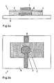
- FIGS Fig. 1a to 1d Mistake In this embodiment, the first electrode 7 directly adjoins the holographic recording material 2.
- the elastic member 4 is thus arranged between the holographic recording material 2 and the counter electrode 8. This is again attached to a substrate 9. When charged or stressed, an attractive or repulsive force acts again between the first electrode 7 and the counterelectrode 8. This causes the holographic recording material 2 to deform and "penetrate" into the elastic element 4, for example.
- a shape of the area can be determined, in which an optically perceptible change in a reconstruction of the hologram upon application of a voltage to the at least two electrodes and / or when the electrodes are charged with a charge.
- the hologram can be stored in the holographic recording material such that it is only completely reconstructed when the at least two electrodes, the first electrode 7 and the counterelectrode 8, are subjected to a predetermined voltage or charge.
- the holographic recording material is deformed accordingly, for example, during exposure of the hologram to the recording material. It should be noted that the holographic recording material usually changes, usually shrinks, in terms of its spatial extent during a development process.
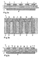
- Fig. 3a and 3b are schematic views of another embodiment of a security element 1 as a sectional view ( Fig. 3a ) and plan view ( Fig. 3b ).
- the first electrode 7 is formed like a comb in this embodiment.
- the counter electrode 8 is formed over the entire surface rectangular.
- the counter electrode may be formed as a complementarily formed comb.
- the elastic element 4 surrounds the holographic Recording material on both the first side 3 and on the opposite side 5 of the recording material 2. This is thus completely embedded in the elastic member 4.
- the holographic recording material may also be formed between two separately formed, optionally made of the same or different material, elastic elements similar to Fig. 1a be arranged and be connected to one of the layers or both layers, for example via a primer, adhesive or the like. Teeth 17 or tines of the first electrode 7 extend in parallel to the holographic recording material 2.
- Fig. 3c is the further embodiment according to Fig. 3a and 3b shown in a state in which the first electrode 7 and the counter electrode 8 are subjected to a voltage or charge.
- a part of the elastic member 4 may be up-well when the first electrode 7 and the counter electrode 8 approach each other.
- the holographic recording material assumes a wave-like structure, so that a reconstruction in the non-charged state, as in Fig. 3a is shown, took place, no longer takes place.
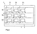
- a further embodiment of a security element is shown schematically, in which the first electrodes are arranged in a plane.
- Fig. 4 is a plan view of a security element 1 is shown.
- the first electrodes 7 are arranged in a matrix-like pattern comprising rows 18 and columns 19.
- the holographic recording material 2 is embedded embedded in the elastic member 4.
- the first electrodes 7 are each connected to each other in an electrically conductive manner.
- the counterelectrodes 8 are, however, connected to each other in an electrically conductive manner in columns.
- the shapes and areal extents of the first electrodes and / or the second electrodes may each differ. This makes it possible to influence different geometric shapes by addressing a single first-electrode counter-electrode pair during a reconstruction.
- the first electrodes or the counter electrodes are transparent, for example of transparent metal oxides such as indium tin oxide (SnO 2 ) ITO, indium zinc oxide, ZnO, antimony tin oxide (ATO) or organic materials such as PEDOT / PSS , Pani®, Orgacon® are made of indium tin oxide (ITO).
- transparent metal oxides such as indium tin oxide (SnO 2 ) ITO, indium zinc oxide, ZnO, antimony tin oxide (ATO) or organic materials such as PEDOT / PSS , Pani®, Orgacon® are made of indium tin oxide (ITO).
- ITO indium tin oxide
- the stored hologram is a transmission hologram
- both the first electrodes and the counterelectrodes are made transparent. The reconstruction of the hologram is observed or detected on an opposite side to the illumination side.
- a reflective layer is provided to reflect back the reconstructed transmission hologram through the holographic recording material so as to be observable or detectable on the side from which the security element is illuminated.
- the reflection can take place, for example, in a metal layer or a reflective form.
- the counter electrode serves as a reflection element.
- the counter electrode is preferably formed of metal.
- the electrodes may be made, for example, by a photolithography process, spin coating, a printing process (eg, screen printing, ink jet printing, offset printing, gravure printing, etc.) or vacuum evaporation or sputtering with metals. Further, shaping can be performed by laser ablation.
- the security element comprises a plurality of first electrodes and / or a plurality of counterelectrodes
- the necessary information for this purpose can be stored, for example, in the security element, preferably in the hologram, particularly preferably encoded.
- this information is stored in a coded manner in the hologram in such a way that it reconstructs in a state in which the first electrodes and / or counterelectrodes are not subjected to voltages and / or charges.
- such information can also be stored on the security element 1 in other ways, for example by printing alphanumeric characters and / or a bar code. It is also possible to store this information in an electronic memory element which is integrated into the security element.
- security elements described can be introduced, for example, into a security document which is produced by means of lamination of several layers. It is also possible to design the security element in such a way that it is glued onto a security document.
Landscapes
- Physics & Mathematics (AREA)
- General Physics & Mathematics (AREA)
- Nonlinear Science (AREA)
- Engineering & Computer Science (AREA)
- Computer Security & Cryptography (AREA)
- Optics & Photonics (AREA)
- Holo Graphy (AREA)
- Credit Cards Or The Like (AREA)
Applications Claiming Priority (2)
| Application Number | Priority Date | Filing Date | Title |
|---|---|---|---|
| DE102008020769A DE102008020769B3 (de) | 2008-04-21 | 2008-04-21 | Sicherheitselement mit einem elektrisch stimulierbaren Volumenhologramm sowie ein Verfahren zu seiner Herstellung |
| PCT/EP2009/002994 WO2009130038A1 (de) | 2008-04-21 | 2009-04-20 | Elektrisch stimulierbares volumenhologramm |
Publications (2)
| Publication Number | Publication Date |
|---|---|
| EP2279446A1 EP2279446A1 (de) | 2011-02-02 |
| EP2279446B1 true EP2279446B1 (de) | 2013-06-19 |
Family
ID=40690312
Family Applications (1)
| Application Number | Title | Priority Date | Filing Date |
|---|---|---|---|
| EP09734333.9A Active EP2279446B1 (de) | 2008-04-21 | 2009-04-20 | Elektrisch stimulierbares volumenhologramm |
Country Status (4)
| Country | Link |
|---|---|
| EP (1) | EP2279446B1 (enExample) |
| JP (1) | JP5613148B2 (enExample) |
| DE (1) | DE102008020769B3 (enExample) |
| WO (1) | WO2009130038A1 (enExample) |
Families Citing this family (5)
| Publication number | Priority date | Publication date | Assignee | Title |
|---|---|---|---|---|
| JP3261741B2 (ja) | 1992-06-30 | 2002-03-04 | スズキ株式会社 | ドア装置 |
| US8715887B2 (en) * | 2010-07-30 | 2014-05-06 | Sabic Innovative Plastics Ip B.V. | Complex holograms, method of making and using complex holograms |
| DE102013225514A1 (de) | 2013-12-10 | 2015-06-11 | Bundesdruckerei Gmbh | Sicherheitselement und Verifikationsverfahren mit einem anregungsabhängigen optischen Effekt im nicht sichtbaren Wellenlängenbereich |
| DE102017001768A1 (de) * | 2017-02-23 | 2018-08-23 | Giesecke+Devrient Currency Technology Gmbh | Sicherheitselement mit PDLC-Folie |
| DE102022115595A1 (de) | 2022-06-22 | 2023-12-28 | Carl Zeiss Jena Gmbh | Replikationsverfahren mit einem kontaktkörper |
Family Cites Families (12)
| Publication number | Priority date | Publication date | Assignee | Title |
|---|---|---|---|---|
| JPH0456887A (ja) * | 1990-06-22 | 1992-02-24 | Nippon Telegr & Teleph Corp <Ntt> | 体積多重ホログラム素子 |
| US5044736A (en) * | 1990-11-06 | 1991-09-03 | Motorola, Inc. | Configurable optical filter or display |
| JPH0546060A (ja) * | 1991-08-21 | 1993-02-26 | Asahi Glass Co Ltd | 体積ホログラム光学フイルムおよびその製造方法およびそれを用いた窓 |
| WO1995002838A1 (en) * | 1993-07-16 | 1995-01-26 | Luckoff Display Corporation | Diffractive display utilizing reflective or transmissive light yielding single pixel full color capability |
| CA2244018C (en) * | 1997-08-06 | 2009-05-26 | Hsm Holographic Systems Muenchen Gmbh | An apparatus for the manufacture of individual holograms to make documents secure |
| AU1209200A (en) * | 1998-10-16 | 2000-11-14 | Digilens Inc. | System and method for modulating light intensity |
| JP2000276627A (ja) * | 1999-03-26 | 2000-10-06 | Nhk Spring Co Ltd | 対象物の識別構造及び識別方法 |
| GB0416140D0 (en) * | 2004-07-19 | 2004-08-18 | Univ Cambridge Tech | Interrogation of a sensor |
| DE102005054396A1 (de) * | 2004-11-26 | 2006-06-01 | Giesecke & Devrient Gmbh | Markierung von Gegenständen mit Vielspiegelelementen |
| US20090207465A1 (en) * | 2005-10-11 | 2009-08-20 | Rodney Riddle | Multiple Security Means Comprising an Interactive Security Element |
| CA2646657A1 (en) * | 2005-10-11 | 2007-04-19 | Smart Holograms Ltd. | Interactive holographic security element |
| DE202007006796U1 (de) * | 2007-05-11 | 2007-08-02 | Prüfbau Dr.-Ing. H. Dürner GmbH | Hologramm-Erzeugungsvorrichtung |
-
2008
- 2008-04-21 DE DE102008020769A patent/DE102008020769B3/de not_active Expired - Fee Related
-
2009
- 2009-04-20 JP JP2011504388A patent/JP5613148B2/ja not_active Expired - Fee Related
- 2009-04-20 WO PCT/EP2009/002994 patent/WO2009130038A1/de not_active Ceased
- 2009-04-20 EP EP09734333.9A patent/EP2279446B1/de active Active
Also Published As
| Publication number | Publication date |
|---|---|
| EP2279446A1 (de) | 2011-02-02 |
| WO2009130038A1 (de) | 2009-10-29 |
| JP2011518351A (ja) | 2011-06-23 |
| DE102008020769B3 (de) | 2009-06-25 |
| JP5613148B2 (ja) | 2014-10-22 |
Similar Documents
| Publication | Publication Date | Title |
|---|---|---|
| AT392439B (de) | Ausweiskarte und verfahren zur herstellung derselben | |
| WO2003089250A2 (de) | Sicherheitsdokument | |
| EP2417491B1 (de) | Piezochromes sicherheitselement auf flüssigkristallbasis | |
| EP1599345B1 (de) | Sicherheitselement mit einer gitterstruktur | |
| EP1648713A2 (de) | Sicherheitselement | |
| EP2155501A2 (de) | Mehrschichtkörper | |
| EP2279446B1 (de) | Elektrisch stimulierbares volumenhologramm | |
| DE102012010908A1 (de) | Verifikation von Wertdokumenten mit einem Fenster mit diffraktiven Strukturen | |
| DE102008036402B3 (de) | Goniolumineszentes Sicherheitselement und Verfahren zu dessen Herstellung | |
| EP2104884B1 (de) | Verfahren zur herstellung eines holographischen sicherheitselementes mit einfarbigen pixeln | |
| EP2209654A2 (de) | Sicherheitsdokument sowie verfahren zu seiner herstellung | |
| DE102012203350A1 (de) | Sicherheitsetikett und ein Verfahren zu seiner Herstellung | |
| DE102008053099A1 (de) | Sicherheitselement mit drucksensitivem Erscheinungsbild | |
| EP2195175B1 (de) | Sicherheits- und/oder wertdokument mit holographischem muster | |
| EP2097792B1 (de) | Herstellungsverfahren für ein holografisches sicherheitselement | |
| DE102008020770B3 (de) | Sicherheitselement mit einem elektrisch stimulierbaren polarisationsabhängigen Volumenhologramm und Verfahren zu dessen Herstellung | |
| EP2200842B1 (de) | Sicherheits- und/oder wertdokument mit in verschiedenen schichten eingerichteten hologrammen | |
| EP2126638A1 (de) | Verfahren zum schreiben holographischer pixel | |
| EP2593310A1 (de) | Sicherheitselement mit hologrammstrukturen | |
| EP2215529B1 (de) | Verfahren und vorrichtung zur herstellung von hologrammen mit individuell belichteter wasserzeichenartiger struktur | |
| DE102022209583B3 (de) | Hologrammmaster für die Herstellung eines Sicherheitselements mit einem optisch variablen holografischen Sicherheitsmerkmal und Herstellungsverfahren sowie Sicherheitselement | |
| DE102007063504A1 (de) | Verfahren und Vorrichtung zur Herstellung von Hologrammen mit individuell belichteter wasserzeichenartiger Stuktur | |
| EP4086076B1 (de) | Verfahren zum herstellen eines laminationskörpers mit integriertem belichtungshologramm | |
| DE102010012495A1 (de) | Sicherheitselement und Herstellungsverfahren dafür |
Legal Events
| Date | Code | Title | Description |
|---|---|---|---|
| PUAI | Public reference made under article 153(3) epc to a published international application that has entered the european phase |
Free format text: ORIGINAL CODE: 0009012 |
|
| 17P | Request for examination filed |
Effective date: 20101118 |
|
| AK | Designated contracting states |
Kind code of ref document: A1 Designated state(s): AT BE BG CH CY CZ DE DK EE ES FI FR GB GR HR HU IE IS IT LI LT LU LV MC MK MT NL NO PL PT RO SE SI SK TR |
|
| AX | Request for extension of the european patent |
Extension state: AL BA RS |
|
| DAX | Request for extension of the european patent (deleted) | ||
| REG | Reference to a national code |
Ref country code: DE Ref legal event code: R079 Ref document number: 502009007380 Country of ref document: DE Free format text: PREVIOUS MAIN CLASS: G02F0001010000 Ipc: G03H0001020000 |
|
| RIC1 | Information provided on ipc code assigned before grant |
Ipc: B42D 15/10 20060101ALI20120816BHEP Ipc: G03H 1/22 20060101ALI20120816BHEP Ipc: G02F 1/01 20060101ALI20120816BHEP Ipc: G03H 1/02 20060101AFI20120816BHEP |
|
| GRAP | Despatch of communication of intention to grant a patent |
Free format text: ORIGINAL CODE: EPIDOSNIGR1 |
|
| GRAP | Despatch of communication of intention to grant a patent |
Free format text: ORIGINAL CODE: EPIDOSNIGR1 |
|
| GRAS | Grant fee paid |
Free format text: ORIGINAL CODE: EPIDOSNIGR3 |
|
| GRAA | (expected) grant |
Free format text: ORIGINAL CODE: 0009210 |
|
| AK | Designated contracting states |
Kind code of ref document: B1 Designated state(s): AT BE BG CH CY CZ DE DK EE ES FI FR GB GR HR HU IE IS IT LI LT LU LV MC MK MT NL NO PL PT RO SE SI SK TR |
|
| REG | Reference to a national code |
Ref country code: GB Ref legal event code: FG4D Free format text: NOT ENGLISH |
|
| REG | Reference to a national code |
Ref country code: CH Ref legal event code: EP |
|
| REG | Reference to a national code |
Ref country code: AT Ref legal event code: REF Ref document number: 617974 Country of ref document: AT Kind code of ref document: T Effective date: 20130715 Ref country code: CH Ref legal event code: NV Representative=s name: PATENTANWALT DIPL.-ING. (UNI.) WOLFGANG HEISEL, CH |
|
| REG | Reference to a national code |
Ref country code: IE Ref legal event code: FG4D Free format text: LANGUAGE OF EP DOCUMENT: GERMAN |
|
| REG | Reference to a national code |
Ref country code: DE Ref legal event code: R096 Ref document number: 502009007380 Country of ref document: DE Effective date: 20130814 |
|
| PG25 | Lapsed in a contracting state [announced via postgrant information from national office to epo] |
Ref country code: GR Free format text: LAPSE BECAUSE OF FAILURE TO SUBMIT A TRANSLATION OF THE DESCRIPTION OR TO PAY THE FEE WITHIN THE PRESCRIBED TIME-LIMIT Effective date: 20130920 Ref country code: LT Free format text: LAPSE BECAUSE OF FAILURE TO SUBMIT A TRANSLATION OF THE DESCRIPTION OR TO PAY THE FEE WITHIN THE PRESCRIBED TIME-LIMIT Effective date: 20130619 Ref country code: FI Free format text: LAPSE BECAUSE OF FAILURE TO SUBMIT A TRANSLATION OF THE DESCRIPTION OR TO PAY THE FEE WITHIN THE PRESCRIBED TIME-LIMIT Effective date: 20130619 Ref country code: SI Free format text: LAPSE BECAUSE OF FAILURE TO SUBMIT A TRANSLATION OF THE DESCRIPTION OR TO PAY THE FEE WITHIN THE PRESCRIBED TIME-LIMIT Effective date: 20130619 Ref country code: NO Free format text: LAPSE BECAUSE OF FAILURE TO SUBMIT A TRANSLATION OF THE DESCRIPTION OR TO PAY THE FEE WITHIN THE PRESCRIBED TIME-LIMIT Effective date: 20130919 Ref country code: SE Free format text: LAPSE BECAUSE OF FAILURE TO SUBMIT A TRANSLATION OF THE DESCRIPTION OR TO PAY THE FEE WITHIN THE PRESCRIBED TIME-LIMIT Effective date: 20130619 Ref country code: ES Free format text: LAPSE BECAUSE OF FAILURE TO SUBMIT A TRANSLATION OF THE DESCRIPTION OR TO PAY THE FEE WITHIN THE PRESCRIBED TIME-LIMIT Effective date: 20130930 |
|
| REG | Reference to a national code |
Ref country code: LT Ref legal event code: MG4D |
|
| PG25 | Lapsed in a contracting state [announced via postgrant information from national office to epo] |
Ref country code: BG Free format text: LAPSE BECAUSE OF FAILURE TO SUBMIT A TRANSLATION OF THE DESCRIPTION OR TO PAY THE FEE WITHIN THE PRESCRIBED TIME-LIMIT Effective date: 20130919 Ref country code: HR Free format text: LAPSE BECAUSE OF FAILURE TO SUBMIT A TRANSLATION OF THE DESCRIPTION OR TO PAY THE FEE WITHIN THE PRESCRIBED TIME-LIMIT Effective date: 20130619 |
|
| REG | Reference to a national code |
Ref country code: NL Ref legal event code: VDEP Effective date: 20130619 |
|
| PG25 | Lapsed in a contracting state [announced via postgrant information from national office to epo] |
Ref country code: LV Free format text: LAPSE BECAUSE OF FAILURE TO SUBMIT A TRANSLATION OF THE DESCRIPTION OR TO PAY THE FEE WITHIN THE PRESCRIBED TIME-LIMIT Effective date: 20130619 |
|
| PG25 | Lapsed in a contracting state [announced via postgrant information from national office to epo] |
Ref country code: CY Free format text: LAPSE BECAUSE OF FAILURE TO SUBMIT A TRANSLATION OF THE DESCRIPTION OR TO PAY THE FEE WITHIN THE PRESCRIBED TIME-LIMIT Effective date: 20130918 Ref country code: IS Free format text: LAPSE BECAUSE OF FAILURE TO SUBMIT A TRANSLATION OF THE DESCRIPTION OR TO PAY THE FEE WITHIN THE PRESCRIBED TIME-LIMIT Effective date: 20131019 Ref country code: SK Free format text: LAPSE BECAUSE OF FAILURE TO SUBMIT A TRANSLATION OF THE DESCRIPTION OR TO PAY THE FEE WITHIN THE PRESCRIBED TIME-LIMIT Effective date: 20130619 Ref country code: CZ Free format text: LAPSE BECAUSE OF FAILURE TO SUBMIT A TRANSLATION OF THE DESCRIPTION OR TO PAY THE FEE WITHIN THE PRESCRIBED TIME-LIMIT Effective date: 20130619 Ref country code: EE Free format text: LAPSE BECAUSE OF FAILURE TO SUBMIT A TRANSLATION OF THE DESCRIPTION OR TO PAY THE FEE WITHIN THE PRESCRIBED TIME-LIMIT Effective date: 20130619 Ref country code: PT Free format text: LAPSE BECAUSE OF FAILURE TO SUBMIT A TRANSLATION OF THE DESCRIPTION OR TO PAY THE FEE WITHIN THE PRESCRIBED TIME-LIMIT Effective date: 20131021 |
|
| PG25 | Lapsed in a contracting state [announced via postgrant information from national office to epo] |
Ref country code: PL Free format text: LAPSE BECAUSE OF FAILURE TO SUBMIT A TRANSLATION OF THE DESCRIPTION OR TO PAY THE FEE WITHIN THE PRESCRIBED TIME-LIMIT Effective date: 20130619 Ref country code: NL Free format text: LAPSE BECAUSE OF FAILURE TO SUBMIT A TRANSLATION OF THE DESCRIPTION OR TO PAY THE FEE WITHIN THE PRESCRIBED TIME-LIMIT Effective date: 20130619 Ref country code: RO Free format text: LAPSE BECAUSE OF FAILURE TO SUBMIT A TRANSLATION OF THE DESCRIPTION OR TO PAY THE FEE WITHIN THE PRESCRIBED TIME-LIMIT Effective date: 20130619 |
|
| PG25 | Lapsed in a contracting state [announced via postgrant information from national office to epo] |
Ref country code: CY Free format text: LAPSE BECAUSE OF FAILURE TO SUBMIT A TRANSLATION OF THE DESCRIPTION OR TO PAY THE FEE WITHIN THE PRESCRIBED TIME-LIMIT Effective date: 20130619 |
|
| PLBE | No opposition filed within time limit |
Free format text: ORIGINAL CODE: 0009261 |
|
| STAA | Information on the status of an ep patent application or granted ep patent |
Free format text: STATUS: NO OPPOSITION FILED WITHIN TIME LIMIT |
|
| PG25 | Lapsed in a contracting state [announced via postgrant information from national office to epo] |
Ref country code: DK Free format text: LAPSE BECAUSE OF FAILURE TO SUBMIT A TRANSLATION OF THE DESCRIPTION OR TO PAY THE FEE WITHIN THE PRESCRIBED TIME-LIMIT Effective date: 20130619 |
|
| 26N | No opposition filed |
Effective date: 20140320 |
|
| PG25 | Lapsed in a contracting state [announced via postgrant information from national office to epo] |
Ref country code: IT Free format text: LAPSE BECAUSE OF FAILURE TO SUBMIT A TRANSLATION OF THE DESCRIPTION OR TO PAY THE FEE WITHIN THE PRESCRIBED TIME-LIMIT Effective date: 20130619 |
|
| REG | Reference to a national code |
Ref country code: DE Ref legal event code: R097 Ref document number: 502009007380 Country of ref document: DE Effective date: 20140320 |
|
| PG25 | Lapsed in a contracting state [announced via postgrant information from national office to epo] |
Ref country code: LU Free format text: LAPSE BECAUSE OF FAILURE TO SUBMIT A TRANSLATION OF THE DESCRIPTION OR TO PAY THE FEE WITHIN THE PRESCRIBED TIME-LIMIT Effective date: 20140420 Ref country code: MC Free format text: LAPSE BECAUSE OF FAILURE TO SUBMIT A TRANSLATION OF THE DESCRIPTION OR TO PAY THE FEE WITHIN THE PRESCRIBED TIME-LIMIT Effective date: 20130619 |
|
| REG | Reference to a national code |
Ref country code: IE Ref legal event code: MM4A |
|
| PG25 | Lapsed in a contracting state [announced via postgrant information from national office to epo] |
Ref country code: IE Free format text: LAPSE BECAUSE OF NON-PAYMENT OF DUE FEES Effective date: 20140420 |
|
| REG | Reference to a national code |
Ref country code: AT Ref legal event code: MM01 Ref document number: 617974 Country of ref document: AT Kind code of ref document: T Effective date: 20140420 |
|
| PG25 | Lapsed in a contracting state [announced via postgrant information from national office to epo] |
Ref country code: AT Free format text: LAPSE BECAUSE OF NON-PAYMENT OF DUE FEES Effective date: 20140420 |
|
| PG25 | Lapsed in a contracting state [announced via postgrant information from national office to epo] |
Ref country code: MT Free format text: LAPSE BECAUSE OF FAILURE TO SUBMIT A TRANSLATION OF THE DESCRIPTION OR TO PAY THE FEE WITHIN THE PRESCRIBED TIME-LIMIT Effective date: 20130619 |
|
| REG | Reference to a national code |
Ref country code: FR Ref legal event code: PLFP Year of fee payment: 8 |
|
| PG25 | Lapsed in a contracting state [announced via postgrant information from national office to epo] |
Ref country code: TR Free format text: LAPSE BECAUSE OF FAILURE TO SUBMIT A TRANSLATION OF THE DESCRIPTION OR TO PAY THE FEE WITHIN THE PRESCRIBED TIME-LIMIT Effective date: 20130619 Ref country code: BE Free format text: LAPSE BECAUSE OF FAILURE TO SUBMIT A TRANSLATION OF THE DESCRIPTION OR TO PAY THE FEE WITHIN THE PRESCRIBED TIME-LIMIT Effective date: 20140430 Ref country code: HU Free format text: LAPSE BECAUSE OF FAILURE TO SUBMIT A TRANSLATION OF THE DESCRIPTION OR TO PAY THE FEE WITHIN THE PRESCRIBED TIME-LIMIT; INVALID AB INITIO Effective date: 20090420 |
|
| REG | Reference to a national code |
Ref country code: FR Ref legal event code: PLFP Year of fee payment: 9 |
|
| REG | Reference to a national code |
Ref country code: FR Ref legal event code: PLFP Year of fee payment: 10 |
|
| PG25 | Lapsed in a contracting state [announced via postgrant information from national office to epo] |
Ref country code: MK Free format text: LAPSE BECAUSE OF FAILURE TO SUBMIT A TRANSLATION OF THE DESCRIPTION OR TO PAY THE FEE WITHIN THE PRESCRIBED TIME-LIMIT Effective date: 20130619 |
|
| P01 | Opt-out of the competence of the unified patent court (upc) registered |
Effective date: 20230526 |
|
| PGFP | Annual fee paid to national office [announced via postgrant information from national office to epo] |
Ref country code: FR Payment date: 20230417 Year of fee payment: 15 Ref country code: DE Payment date: 20230418 Year of fee payment: 15 Ref country code: CH Payment date: 20230502 Year of fee payment: 15 |
|
| PGFP | Annual fee paid to national office [announced via postgrant information from national office to epo] |
Ref country code: GB Payment date: 20230420 Year of fee payment: 15 |
|
| REG | Reference to a national code |
Ref country code: DE Ref legal event code: R119 Ref document number: 502009007380 Country of ref document: DE |
|
| REG | Reference to a national code |
Ref country code: CH Ref legal event code: PL |
|
| GBPC | Gb: european patent ceased through non-payment of renewal fee |
Effective date: 20240420 |
|
| PG25 | Lapsed in a contracting state [announced via postgrant information from national office to epo] |
Ref country code: DE Free format text: LAPSE BECAUSE OF NON-PAYMENT OF DUE FEES Effective date: 20241105 |
|
| PG25 | Lapsed in a contracting state [announced via postgrant information from national office to epo] |
Ref country code: GB Free format text: LAPSE BECAUSE OF NON-PAYMENT OF DUE FEES Effective date: 20240420 |
|
| PG25 | Lapsed in a contracting state [announced via postgrant information from national office to epo] |
Ref country code: FR Free format text: LAPSE BECAUSE OF NON-PAYMENT OF DUE FEES Effective date: 20240430 |
|
| PG25 | Lapsed in a contracting state [announced via postgrant information from national office to epo] |
Ref country code: GB Free format text: LAPSE BECAUSE OF NON-PAYMENT OF DUE FEES Effective date: 20240420 Ref country code: FR Free format text: LAPSE BECAUSE OF NON-PAYMENT OF DUE FEES Effective date: 20240430 Ref country code: DE Free format text: LAPSE BECAUSE OF NON-PAYMENT OF DUE FEES Effective date: 20241105 Ref country code: CH Free format text: LAPSE BECAUSE OF NON-PAYMENT OF DUE FEES Effective date: 20240430 |