EP2279406B1 - Vorrichtung und Verfahren zur Erkennung von Elementen in einem Fluidmedium mittels Lambwellen - Google Patents
Vorrichtung und Verfahren zur Erkennung von Elementen in einem Fluidmedium mittels Lambwellen Download PDFInfo
- Publication number
- EP2279406B1 EP2279406B1 EP09738335.0A EP09738335A EP2279406B1 EP 2279406 B1 EP2279406 B1 EP 2279406B1 EP 09738335 A EP09738335 A EP 09738335A EP 2279406 B1 EP2279406 B1 EP 2279406B1
- Authority
- EP
- European Patent Office
- Prior art keywords
- electrodes
- resonator
- resonance frequency
- elements
- upper electrodes
- Prior art date
- Legal status (The legal status is an assumption and is not a legal conclusion. Google has not performed a legal analysis and makes no representation as to the accuracy of the status listed.)
- Not-in-force
Links
Images

Classifications
-
- G—PHYSICS
- G01—MEASURING; TESTING
- G01N—INVESTIGATING OR ANALYSING MATERIALS BY DETERMINING THEIR CHEMICAL OR PHYSICAL PROPERTIES
- G01N29/00—Investigating or analysing materials by the use of ultrasonic, sonic or infrasonic waves; Visualisation of the interior of objects by transmitting ultrasonic or sonic waves through the object
- G01N29/02—Analysing fluids
- G01N29/022—Fluid sensors based on microsensors, e.g. quartz crystal-microbalance [QCM], surface acoustic wave [SAW] devices, tuning forks, cantilevers, flexural plate wave [FPW] devices
-
- G—PHYSICS
- G01—MEASURING; TESTING
- G01N—INVESTIGATING OR ANALYSING MATERIALS BY DETERMINING THEIR CHEMICAL OR PHYSICAL PROPERTIES
- G01N2291/00—Indexing codes associated with group G01N29/00
- G01N2291/01—Indexing codes associated with the measuring variable
- G01N2291/014—Resonance or resonant frequency
-
- G—PHYSICS
- G01—MEASURING; TESTING
- G01N—INVESTIGATING OR ANALYSING MATERIALS BY DETERMINING THEIR CHEMICAL OR PHYSICAL PROPERTIES
- G01N2291/00—Indexing codes associated with group G01N29/00
- G01N2291/02—Indexing codes associated with the analysed material
- G01N2291/025—Change of phase or condition
- G01N2291/0255—(Bio)chemical reactions, e.g. on biosensors
-
- G—PHYSICS
- G01—MEASURING; TESTING
- G01N—INVESTIGATING OR ANALYSING MATERIALS BY DETERMINING THEIR CHEMICAL OR PHYSICAL PROPERTIES
- G01N2291/00—Indexing codes associated with group G01N29/00
- G01N2291/02—Indexing codes associated with the analysed material
- G01N2291/025—Change of phase or condition
- G01N2291/0256—Adsorption, desorption, surface mass change, e.g. on biosensors
-
- G—PHYSICS
- G01—MEASURING; TESTING
- G01N—INVESTIGATING OR ANALYSING MATERIALS BY DETERMINING THEIR CHEMICAL OR PHYSICAL PROPERTIES
- G01N2291/00—Indexing codes associated with group G01N29/00
- G01N2291/04—Wave modes and trajectories
- G01N2291/042—Wave modes
- G01N2291/0427—Flexural waves, plate waves, e.g. Lamb waves, tuning fork, cantilever
Definitions
- the detection of elements in an aqueous medium can be done using the variation of the resonance frequency of an acoustic resonator.
- One possible application of these detectors is to observe the hybridization of molecules on appropriate receptors.
- An integrated device comprising detectors in parallel, on each of which have been deposited chemical receptors, can be immersed to perform a collective detection process. This process is a chemical process.
- molecules are likely to hybridize to the receptors grafted on each resonator. If a molecule hybridizes, it becomes integral with the resonator and changes the resonant frequency.
- the elements affect the resonance frequency of the resonator. This frequency change of the resonator can then be observed by electrical detection.
- Such devices conventionally use surface acoustic waves (SAW).
- SAW surface acoustic waves
- the SAW devices must present an acoustic wave which must not lose energy in the water, in fact a loss of energy would greatly reduce the sensitivity of the device.
- the acoustic waves are generated so as to be parallel to the surface in contact with the liquid.
- Surface acoustic wave devices are well suited insofar as it is possible to generate shear waves, which induce a wave shift only in the plane of the resonator.
- surface acoustic wave devices have the disadvantage of requiring a gold piezoelectric substrate, the silicon generally used for microelectronics is not a piezoelectric substrate. The realization of such devices can not be made at low cost by conventional methods of microelectronics, especially on substrates 200mm in diameter.
- Lamb waves Another possibility is to use so-called Lamb waves and to ensure that the acoustic waves can not propagate in the liquid.
- the Lamb wave is a wave of volume that can propagate in a plate, that is to say in a solid medium whose thickness is very small in front of its lateral dimensions.
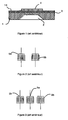
- this device comprises a silicon substrate 1, in which a cavity 2 is formed, covered by a membrane 3 of silicon or silicon oxide (SiO 2) and by a metal plane 14, this assembly being itself covered by a stack
- the stack 4 comprises a layer of piezoelectric material, for example aluminum nitride or zinc oxide on which electrodes (not shown in FIG. figure 1 ).
- the device may comprise as illustrated at figure 2 , two sets of interdigitated electrodes, an excitation electrode 5a of the piezoelectric material and a second control electrode 5b forming a delay line.
- the excitation electrode 5a is disposed between two control electrodes 5b.
- the measurement of the propagation time between the excitation electrode 5a and the control electrode or electrodes 5b represents the speed of propagation of the acoustic waves in an aqueous medium.
- the device comprises at least one acoustic resonator provided with a surface for fixing said elements.
- the resonator includes means for generating Lamb waves, and electrodes for providing signals representative of the resonance frequency of the resonator.
- the measurement electrodes are connected to electronic processing means.
- the patent US 5,212,988 discloses a device using a transducer coupled to a medium for generating symmetrical and antisymmetric Lamb waves in the medium.
- the transducer may be of the type of a port, ie it generates and measures the Lamb waves in the medium. Such a device is not optimal, the energy not being maximized in the resonant structure.
- the object of the invention is to provide an element detection device, easy to make and use.
- the acoustic resonator comprises a piezoelectric stack delimited by two longitudinal lateral faces, the generation and measurement means comprising an odd number, greater than or equal to three, of upper electrodes, longitudinal, said upper electrodes being uniformly distributed on an upper face of the piezoelectric stack, each longitudinal side face of the piezoelectric stack being aligned with an edge of an associated upper electrode, two adjacent upper electrodes having an opposite polarity, the upper electrodes of the same polarity being electrically connected to each other, at least one lower electrode being disposed on a lower face of the piezoelectric stack.
- the device comprises a single floating potential lower electrode covering the entire lower face of the piezoelectric stack.
- the device comprises a number of lower electrodes equal to the number of upper electrodes, each lower electrode being disposed facing an upper electrode. corresponding, two adjacent lower electrodes having an opposite polarity, the upper and lower electrodes of the same polarity being electrically interconnected.
- the upper and lower electrodes opposite have the same polarity or an opposite polarity.
- the device for detecting elements in a fluid medium comprises at least one acoustic resonator 6 provided with a surface 7 for fixing the elements to detect their presence.
- the resonator 6 comprises means 8 for generating and measuring Lamb waves, making it possible both to generate symmetrical Lamb waves and to provide signals representative of the resonance frequency of the resonator 6.
- the electronic means 9 for processing are connected to the generation and measurement means 8 of the resonator 6, these electronic means 9 allow the interpretation of the signals provided by the generating and measuring means.
- the device does not generate acoustic waves in the fluid.
- the acoustic polarization corresponds to the displacement of a point of the surface of a vertical and / or horizontal material.
- the resonance frequency of the resonator is lower than the frequency of displacement of the acoustic waves in the fluid.
- antisymmetric Lamb waves are widely used. It is indeed possible to obtain antisymmetric Lamb waves at very low frequencies, close to 0 Hz, well below the frequency of acoustic waves moving in the fluid.
- the present invention is based on the use of symmetrical Lamb waves. Although these waves are conventionally considered as parasitic waves inducing a wave in the fluid which disperses the acoustic energy, they can be, contrary to the prejudices when they are used correctly, used to detect the presence of elements in a fluidic medium. When symmetrical Lamb waves are used in a device promoting them, the resulting acoustic polarization is almost horizontal. The vertical components are little present thus avoiding the generation of longitudinal acoustic waves in the fluid.
- the Lamb wave generation and measurement means 8 are means promoting the generation of symmetrical Lamb waves.
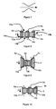
- the acoustic resonator comprises a piezoelectric stack 4 delimited by two longitudinal lateral faces 14a and 14b and the generation and measurement means 8 comprise on an upper face of the piezoelectric stack an odd number, greater than or equal to three, of longitudinal upper electrodes 5a, 5b, 5c.
- the upper electrodes 5a, 5b, 5c are uniformly distributed on the upper face 15a of the piezoelectric stack 4. Each longitudinal side face 14a, 14b of the stack is aligned with an edge 16 of an associated upper electrode 5a, 5c on the figure 5 . Two adjacent upper electrodes have opposite polarity, the electrodes of the same polarity being electrically connected to each other. At least one lower electrode is disposed on a lower face of the piezoelectric stack 4. The variation is measured by the upper and / or lower electrodes and then transmitted to the electronic processing means 9 for interpretation.
- the resonance frequency of the resonator in the fluid medium is measured by the upper and / or lower electrodes and then interpreted by the electronic processing means 9.
- the electronic means 9 determine whether the variation between the resonance frequency in a fluid medium and the reference resonant frequency corresponds to the presence of certain elements in the fluid.
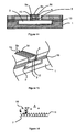
- a hybridization layer may cover a portion or the entire resonator so as to form the surface 7 for fixing the elements.
- this layer comprises receivers 11 adapted to certain elements 10, so when the resonator is immersed in the fluid some elements 10 can hybridize on the receptors 11, the hybridization then causes a modification of the mass of the resonator inducing a variation of the resonance frequency.
- the receptors are formed on an organic layer covering the surface 7.
- the acoustic resonator generating symmetrical Lamb waves comprises a piezoelectric stack 4 delimited by two longitudinal lateral faces 14a and 14b.
- the two lateral faces 14a and 14b can be, as on the figure 5 , substantially parallel to each other and of the same height so as to connect the upper face 15a and lower 15b of the piezoelectric stack 4.
- the Lamb wave generation and measurement means 8 of the resonator preferably comprise at least three upper electrodes 5a, 5b and 5c, substantially parallel and arranged on the upper face 15a of the piezoelectric stack 4.
- the upper electrodes 5a, 5b, 5c are longitudinal and are arranged so that the upper electrodes 5a and 5c each have an edge 16 aligned to a side face 14a, 14b associated. So, on the figure 5 the interface of each side face 14a, 14b with the upper face 15a forms an edge at which is disposed an upper electrode 5a, 5c.
- a lower floating potential electrode 12 is disposed under the piezoelectric stack 4 so that the lower face 15b is completely covered by the lower electrode 12.
- the piezoelectric stack comprises at least one layer of piezoelectric material.
- the upper electrodes 5a and 5c have the same polarity (+) while the upper central electrode 5b is of opposite polarity (-) to the polarity of the upper electrodes 5a and 5c.
- the symmetrical Lamb wave generating means may comprise means for applying a voltage (+/-) between the upper electrodes of opposite polarity.
- the upper electrodes of the same polarity are electrically connected to each other.
- the structure of the resonator of the figure 5 deforms according to a profile substantially corresponding to the symmetrical Lamb wave profile ( figure 7 ) by applying an alternating voltage between the upper electrodes 5a / 5b and 5b / 5c at a frequency corresponding to the resonance of a vibration mode generating symmetrical Lamb waves.
- This deformation is explained by a deformation field generated in the piezoelectric stack 4.
- the thickness of the The piezoelectric stack 4 will increase between the upper electrode 5a and 5c and the floating potential electrode 12. Conversely, in the areas where an upper electrode 5b is negatively polarized, the piezoelectric stack 4 will tend to reduce its thickness.
- the number of upper electrodes is not limited to three, it is possible to have as many electrodes as desired since their number is odd and two adjacent upper electrodes are of opposite polarity.
- the means for generating and measuring Lamb waves comprise a plurality of lower electrodes 12a, 12b and 12c each being disposed on the lower face of the piezoelectric stack opposite a corresponding upper electrode 5a, 5b and 5c, to form electrode pairs 5a / 12a, 5b / 12b and 5c / 12c.
- Two adjacent lower electrodes are of opposite polarity.
- the means for generating and measuring symmetrical Lamb waves then comprise means for applying a voltage between the electrodes of a pair of electrodes 5a / 12a, 5b / 12b and 5c / 12c.
- the upper and lower electrodes of the same polarity are electrically interconnected.
- the opposite upper and lower electrodes have opposite polarity. So, on the figure 8 the upper electrodes 5a and 5c have a positive polarity (+) and the upper electrode 5b has a negative polarity (-) while the lower electrodes 12a and 12c have a negative polarity (-) and the lower electrode 12b has a positive polarity. It is then obtained, on the same principle as above, a deformation of the resonator ( figure 9 ) in the case where the piezoelectric stack 4 has its electric polarization P downwards.
- the device always comprises a number of lower electrodes 12a, 12b, 12c equal to the number of upper electrodes 5a, 5b, 5c, each lower electrode 12a, 12b, 12c being arranged facing an upper electrode 5a, 5b, 5c corresponding.
- Two adjacent lower electrodes have opposite polarity and the upper and lower electrodes of the same polarity being electrically connected to each other.
- the upper and lower electrodes opposite have the same polarity. So, on this figure 10 the upper electrodes 5a and 5c and the lower electrodes 12a and 12c have a positive polarity (+) while the upper electrode 5b and the lower electrode 12b have a negative polarity.
- the piezoelectric stack 4 has a thickness of about 10 nm to 5 ⁇ m, in particular to ensure sufficient rigidity to the membrane.
- a piezoelectric material type AIN or Pb (Ze, Ti) O 3 (called PZT) or ZnO are examples of piezoelectric material types.
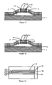
- the device for detecting elements in a fluid medium comprises a substrate 1.
- a finger-shaped membrane 3, one end of which is anchored to the substrate 1, is formed above the substrate 1 so as to delimit a cavity 2 between the membrane 3 and the substrate 1.
- the piezoelectric stack 4 is formed on the membrane 3 and comprises at least one layer of piezoelectric material supporting the upper electrodes 5a, 5b, 5c disposed on the stack piezoelectric device 4.
- the lower electrode or electrodes (12, 12a, 12b, 12c) are arranged between the membrane 3 and the stack 4. In fine, the membrane 3 is released by the etching of the sacrificial layer, thus forming the cavity 2 .
- the membrane 3 may also comprise two anchoring points (not shown) to the substrate so as to form a bridge whose two ends are anchored to the substrate, the piezoelectric stack being carried by the bridge.
- the device can be obtained from a silicon substrate 1 on which thermal oxidation is performed to form a silicon oxide layer 13.
- This layer 13 is preferably 0.5 ⁇ m thick.
- a polymer is deposited as a layer sacrificial later delimiting the cavity 2 trapezoidal shape.
- This sacrificial layer preferably has a thickness of 1.5 ⁇ m.
- a layer of silicon nitride intended to constitute the membrane 3 is then deposited, for example by PECVD, on the silicon oxide layer 13 and on the sacrificial layer. It preferably has a thickness of 400 nm.
- a stack is then made comprising the lower electrode or electrodes 12, 12a, 12b, 12c, then the layer of piezoelectric material forming the stack 4, preferably made of aluminum nitride, and finally the upper electrodes 5a, 5b and 5c. .
- the lower electrode or electrodes 12 are made by platinum (Pt) sputtering, to form a layer which can measure a thickness of 100 nm and this layer, which can preferably be 100 nm thick, is then etched by ionic machining. to form the lower electrode (s) prior to deposition of the piezoelectric material layer.
- An aluminum nitride layer about 1 .mu.m thick to form the layer of piezoelectric material, is then sprayed over the entire device.
- Stacking is then etched to the level of the sacrificial layer so that the piezoelectric stack is delimited by the two lateral faces 14a and 14b. This etching of the stack is carried out by ionic etching of the upper layer of platinum forming the upper electrodes 5a, 5b, 5c, wet etching for the aluminum nitride layer forming the piezoelectric stack 4, and reactive ion etching for the Silicon nitride layer forming the membrane 3.
- the sacrificial layer is removed in an oxygen plasma to form a cavity 2.
- the membrane 3, the lower electrode 12, the piezoelectric stack 4 and the upper electrodes 5a, 5b , 5c thus form, in a plane perpendicular to Figures 11 and 12 , a finger above the cavity 2 to form the resonator as shown in FIG. figure 15 .
- the cavity 2 is formed in the substrate 1. This is, for example, etched before oxidation to form the cavity 2.
- the oxidized layer 13 is then produced and the sacrificial layer is constituted by a polymer filling the cavity 2.
- the production of the membrane 3, the piezoelectric stack and the release of the membrane 3 by removal of the sacrificial layer are then performed as described previously ( figure 15 ).
- the latter can be covered with an insulator (not shown).
- the device produced can be directly immersed in the fluid medium.
- the device produced does not show a variation of the resonance when it is placed in the presence of an aqueous medium.
- the acoustic waves generated in the aqueous medium are therefore negligible.
- the device can be used directly in the fluid medium, while some devices require first a dipping of the structure in the fluid medium, evaporation of water, then only an electrical test. With this new device, the test can be performed directly in the aqueous medium, resulting in a very significant time saving.
- Each resonator may then include a surface for fixing a different type of elements.
- Each surface is then provided with receivers allowing the hybridization of elements, so when each resonator is placed at its resonance frequency corresponding to the generation of symmetrical Lamb waves, the substrate comprising the different resonators can be immersed in the fluid and the electronic processing means are capable of analyzing the content of the fluid according to the measurements of the resonant frequency of each resonator.
- putting the resonator at its resonance frequency comprises a calibration step of the detection device.
- the device when determining the standard frequency, the device is placed in the air or in water.
- the calibration can be carried out by varying the excitation frequency of the Lamb wave generation means until an impedance peak is measured at the level of the means of generation and measurement, the peak then corresponding to the resonance frequency at which symmetrical Lamb waves are generated in the resonator.
- a piezoelectric material makes it possible, by electrical excitation, to apply a mechanical deformation to the material, so as to generate symmetrical Lamb waves in the material when the impedance peak is reached. Then, when the resonator is immersed in a fluid, if elements hybridize with the latter, the deformation of the piezoelectric material is modified, thus implying an impedance or voltage variation across the generating and measuring means.
- the use of a device according to the invention makes it possible to maximize the elastic energy in the resonant structure and thus to improve the sensitivity of the device.
Landscapes
- Physics & Mathematics (AREA)
- Acoustics & Sound (AREA)
- Health & Medical Sciences (AREA)
- Life Sciences & Earth Sciences (AREA)
- Chemical & Material Sciences (AREA)
- Analytical Chemistry (AREA)
- Biochemistry (AREA)
- General Health & Medical Sciences (AREA)
- General Physics & Mathematics (AREA)
- Immunology (AREA)
- Pathology (AREA)
- Investigating Or Analyzing Materials By The Use Of Ultrasonic Waves (AREA)
- Piezo-Electric Or Mechanical Vibrators, Or Delay Or Filter Circuits (AREA)
Claims (10)
- Vorrichtung zur Erfassung von Elementen in einem Fluidmedium mit:- mindestens einem akustischen Resonator (6), der mit einer zur Festlegung dieser Elemente vorgesehenen Oberfläche (7) versehen ist, wobei der Resonator Einrichtungen zur Erzeugung und Messung (8) von Lambwellen aufweist, die gleichzeitig die Erzeugung der symmetrischen Lambwellen mit der Resonanzfrequenz des Resonators und die Lieferung von Signalen ermöglichen, die die Resonanzfrequenz des Resonators (6) darstellen,- elektronischen Verarbeitungseinrichtungen (9), die mit den Einrichtungen zur Erzeugung und Messung (8) des Resonators (6) verbunden sind und die Bestimmung der Änderung der Resonanzfrequenz des Resonators ermöglichen, die das Vorliegen der Elementen in dem Fluid darstellt,dadurch gekennzeichnet, dass der akustische Resonator (6) einen piezoelektrischen Stapel (4) umfasst, der von zwei längs verlaufenden Seitenflächen (14a, 14b) begrenzt ist, wobei die Einrichtungen zur Erzeugung und Messung (8) eine ungerade Zahl, welche höher oder gleich drei ist, von längs verlaufenden oberen Elektroden (5a, 5b,
5c) aufweist, wobei die oberen Elektroden (5a, 5b, 5c) gleichmäßig über eine obere Fläche (15a) des piezoelektrischen Stapels (4) verteilt sind, wobei jede längs verlaufende Seitenfläche (14a, 14b) des piezoelektrischen Stapels (4) mit einem Rand einer zugeordneten oberen Elektrode ausgerichtet ist, wobei zwei benachbarte obere Elektroden (5a, 5b) eine entgegengesetzte Polarität aufweisen, wobei die oberen Elektroden (5a, 5b, 5c) mit gleicher Polarität untereinander elektrisch verbunden sind, wobei mindestens eine untere Elektrode (12, 12a, 12b, 12c) auf einer Unterseite (15b) des piezoelektrischen Stapels (4) angeordnet ist. - Vorrichtung gemäß Anspruch 1, dadurch gekennzeichnet, dass die Einrichtungen zur Erzeugung und Messung (8) Einrichtungen zum Aufbringen einer Spannung zwischen den oberen Elektroden mit entgegengesetzter Polarität aufweisen.
- Vorrichtung gemäß einem der Ansprüche 1 und 2, dadurch gekennzeichnet, dass sie eine einzelne untere Elektrode (12) mit schwankendem Potential umfasst, welche die gesamte Unterseite (15b) des piezoelektrischen Stapels (4) bedeckt.
- Vorrichtung gemäß einem der Ansprüche 1 und 2, dadurch gekennzeichnet, dass sie eine Anzahl an unteren Elektroden (12a, 12b, 12c) umfasst, die der Anzahl der oberen Elektroden (5a, 5b, 5c) entspricht, wobei jede untere Elektrode (12a, 12b, 12c) gegenüber einer entsprechenden oberen Elektrode (5a, 5b, 5c) angeordnet ist, wobei zwei benachbarte untere Elektroden (12a, 12b, 12c) eine entgegengesetzte Polarität aufweisen, wobei die oberen (5a, 5b, 5c) und unteren Elektroden (12a, 12b, 12c) mit gleicher Polarität untereinander elektrisch verbunden sind.
- Vorrichtung gemäß Anspruch 4, dadurch gekennzeichnet, dass die gegenüberliegenden oberen (5a, 5b, 5c) und unteren Elektroden (12a, 12b, 12c) eine gleiche Polarität aufweisen.
- Vorrichtung gemäß Anspruch 4, dadurch gekennzeichnet, dass die gegenüberliegenden oberen (5a, 5b, 5c) und unteren Elektroden (12a, 12b, 12c) eine entgegengesetzte Polarität aufweisen
- Vorrichtung gemäß einem der Ansprüche 1 bis 6, dadurch gekennzeichnet, dass der piezoelektrische Stapel (4) eine Dicke zwischen 10nm und 5µm aufweist.
- Vorrichtung gemäß einem der Ansprüche 1 bis 7, dadurch gekennzeichnet, dass die Empfänger (11) für bestimmte Elemente (10) auf der Oberfläche (7) des Resonators platziert sind, wobei das Einsetzen der Vorrichtung in das Fluid zur Hybridisierung der mit den Empfängern (11) korrespondierenden Elementen (10) vorgesehen ist, um eine Änderung der Resonanzfrequenz herbeizuführen.
- Verfahren zur Erfassung von Elementen in einem Fluidmedium mit Hilfe einer Erfassungsvorrichtung gemäß einem der Ansprüche 1 bis 8, dadurch gekennzeichnet, dass es die folgenden aufeinanderfolgenden Schritte umfasst:- Bestimmen einer Normalresonanzfrequenz entsprechend der Erzeugung von symmetrischen Lambwellen,- Einsetzen der Erfassungsvorrichtung gemäß einem der Ansprüche 1 bis 8 in das Fluidmedium,- Messen der Resonanzfrequenz der symmetrischen Lambwellen in dem Fluidmedium,- Erfassen dieser Elemente in Abhängigkeit von dem Unterschied zwischen der Resonanzfrequenz in dem Fluidmedium und der Normalresonanzfrequenz.
- Verfahren gemäß Anspruch 9, dadurch gekennzeichnet, dass während der Bestimmung der Normalfrequenz die Vorrichtung in der Luft oder im Wasser angebracht ist.
Applications Claiming Priority (2)
| Application Number | Priority Date | Filing Date | Title |
|---|---|---|---|
| FR0802034A FR2930033A1 (fr) | 2008-04-14 | 2008-04-14 | Dispositif et procede de detection d'elements en milieu fluidique |
| PCT/FR2009/000428 WO2009133301A2 (fr) | 2008-04-14 | 2009-04-14 | Dispositif et procede de detection d'elements en milieu fluidique |
Publications (2)
| Publication Number | Publication Date |
|---|---|
| EP2279406A2 EP2279406A2 (de) | 2011-02-02 |
| EP2279406B1 true EP2279406B1 (de) | 2013-07-31 |
Family
ID=39940591
Family Applications (1)
| Application Number | Title | Priority Date | Filing Date |
|---|---|---|---|
| EP09738335.0A Not-in-force EP2279406B1 (de) | 2008-04-14 | 2009-04-14 | Vorrichtung und Verfahren zur Erkennung von Elementen in einem Fluidmedium mittels Lambwellen |
Country Status (5)
| Country | Link |
|---|---|
| US (1) | US8667845B2 (de) |
| EP (1) | EP2279406B1 (de) |
| JP (1) | JP2011517249A (de) |
| FR (1) | FR2930033A1 (de) |
| WO (1) | WO2009133301A2 (de) |
Families Citing this family (3)
| Publication number | Priority date | Publication date | Assignee | Title |
|---|---|---|---|---|
| US10830738B2 (en) * | 2016-11-14 | 2020-11-10 | University Of Alberta | Ultrasensitive high Q-factor AT-cut-quartz crystal microbalance femtogram mass sensor |
| CN108444570A (zh) * | 2018-04-13 | 2018-08-24 | 东莞理工学院 | 一种谐振式液位测量装置 |
| CN114826200A (zh) * | 2022-05-25 | 2022-07-29 | 深圳技术大学 | 一种体波滤波器及其制备方法 |
Family Cites Families (7)
| Publication number | Priority date | Publication date | Assignee | Title |
|---|---|---|---|---|
| US5212988A (en) * | 1988-02-29 | 1993-05-25 | The Reagents Of The University Of California | Plate-mode ultrasonic structure including a gel |
| US5189914A (en) * | 1988-02-29 | 1993-03-02 | The Regents Of The University Of California | Plate-mode ultrasonic sensor |
| US5076094A (en) * | 1990-10-03 | 1991-12-31 | The United States Of America As Represented By The United States Department Of Energy | Dual output acoustic wave sensor for molecular identification |
| US5571944A (en) * | 1994-12-20 | 1996-11-05 | Sandia Corporation | Acoustic wave (AW) based moisture sensor for use with corrosive gases |
| EP1266214B1 (de) * | 2000-03-20 | 2009-09-23 | The Charles Stark Draper Laboratory, INC. | Biegewellensensor |
| US7451649B2 (en) * | 2005-03-25 | 2008-11-18 | P.J. Edmonson Ltd. | Differentiation and identification of analogous chemical or biological substances with biosensors |
| US20060254356A1 (en) * | 2005-05-11 | 2006-11-16 | Honeywell International, Inc. | Wireless and passive acoustic wave liquid conductivity sensor |
-
2008
- 2008-04-14 FR FR0802034A patent/FR2930033A1/fr active Pending
-
2009
- 2009-04-14 WO PCT/FR2009/000428 patent/WO2009133301A2/fr not_active Ceased
- 2009-04-14 US US12/937,856 patent/US8667845B2/en active Active
- 2009-04-14 EP EP09738335.0A patent/EP2279406B1/de not_active Not-in-force
- 2009-04-14 JP JP2011504496A patent/JP2011517249A/ja not_active Withdrawn
Also Published As
| Publication number | Publication date |
|---|---|
| US20110072901A1 (en) | 2011-03-31 |
| EP2279406A2 (de) | 2011-02-02 |
| US8667845B2 (en) | 2014-03-11 |
| WO2009133301A2 (fr) | 2009-11-05 |
| JP2011517249A (ja) | 2011-05-26 |
| FR2930033A1 (fr) | 2009-10-16 |
| WO2009133301A3 (fr) | 2009-12-30 |
Similar Documents
| Publication | Publication Date | Title |
|---|---|---|
| EP2211143B1 (de) | Planarer mikromechanischer Kreisel mit Messung ausserhalb der Ebene mittels Dehnungsmesser | |
| EP1519213B1 (de) | Bimorph angetriebener, schwingender Mikrospiegel | |
| EP2616386B1 (de) | In der ebene betätigte resonanzvorrichtung und verfahren zur herstellung der vorrichtung | |
| WO2010057992A1 (fr) | Cellule cmut formee d'une membrane de nano-tubes ou de nano-fils ou de nano-poutres | |
| WO2008043737A2 (fr) | Accelerometre resonant comportant un resonateur en forme de diapason equipe de balourds | |
| CH639762A5 (fr) | Transducteur de pression a element vibrant. | |
| EP2279406B1 (de) | Vorrichtung und Verfahren zur Erkennung von Elementen in einem Fluidmedium mittels Lambwellen | |
| EP3424875B1 (de) | Sensorvorrichtung auf der basis von nanodrähten mit zunehmender länge | |
| WO2014049062A1 (fr) | Capteur de pression a base de nanojauges couplees a un resonateur | |
| EP4168791B1 (de) | Eingetauchter umweltsensor mit mitteln gegen verschmutzung | |
| EP3490928B1 (de) | Resonanter chemischer sensor mit einer funktionalisierungsvorrichtung und verfahren zur herstellung davon | |
| FR3021309A1 (fr) | Dispositif microelectronique et/ou nanoelectronique capacitif a compacite augmentee | |
| EP2866020B1 (de) | Vorrichtung zur elektromechanischen Erfassung, zur gravimetrischen Erfassung | |
| CH697478B1 (fr) | Système d'électrodes pour capteur électrochimique et procédé de détermination du PH d'une eau chlorée. | |
| EP2730025B1 (de) | Volumenwellenresonator mit schwingungserregung/-erfassung | |
| EP4481377B1 (de) | System und verfahren zur messung mindestens einer eigenschaft eines partikels mit einem mechanischen resonator und einem mechanisch gekoppelten gravimetrischen sensor | |
| EP3034183A1 (de) | Akustische vorrichtung zur galvanischen isolierung | |
| EP1695031A1 (de) | Mikrobearbeitete vibrierende struktur und assoziiertes mikrogyroskop | |
| WO2004102796A1 (fr) | Resonateurs integres et base de temps incorporant de tels resonateurs | |
| FR3131291A1 (fr) | Procédé de fonctionnalisation d’une membrane d’un capteur électromécanique résonant | |
| EP3910344A1 (de) | Detektionsvorrichtung mit piezoresistivem wandler | |
| FR2977940A1 (fr) | Dispositif pour le controle non-destructif et/ou la caracterisation d'une structure ou d'un materiau | |
| Nicu et al. | Actuation and sensing integration challenges at the microscale: the Gordian Knot of the resonant bioMEMS realm |
Legal Events
| Date | Code | Title | Description |
|---|---|---|---|
| PUAI | Public reference made under article 153(3) epc to a published international application that has entered the european phase |
Free format text: ORIGINAL CODE: 0009012 |
|
| 17P | Request for examination filed |
Effective date: 20101110 |
|
| AK | Designated contracting states |
Kind code of ref document: A2 Designated state(s): AT BE BG CH CY CZ DE DK EE ES FI FR GB GR HR HU IE IS IT LI LT LU LV MC MK MT NL NO PL PT RO SE SI SK TR |
|
| AX | Request for extension of the european patent |
Extension state: AL BA RS |
|
| DAX | Request for extension of the european patent (deleted) | ||
| GRAP | Despatch of communication of intention to grant a patent |
Free format text: ORIGINAL CODE: EPIDOSNIGR1 |
|
| GRAS | Grant fee paid |
Free format text: ORIGINAL CODE: EPIDOSNIGR3 |
|
| GRAA | (expected) grant |
Free format text: ORIGINAL CODE: 0009210 |
|
| AK | Designated contracting states |
Kind code of ref document: B1 Designated state(s): AT BE BG CH CY CZ DE DK EE ES FI FR GB GR HR HU IE IS IT LI LT LU LV MC MK MT NL NO PL PT RO SE SI SK TR |
|
| REG | Reference to a national code |
Ref country code: GB Ref legal event code: FG4D Free format text: NOT ENGLISH Ref country code: CH Ref legal event code: EP |
|
| REG | Reference to a national code |
Ref country code: AT Ref legal event code: REF Ref document number: 624927 Country of ref document: AT Kind code of ref document: T Effective date: 20130815 |
|
| REG | Reference to a national code |
Ref country code: IE Ref legal event code: FG4D Free format text: LANGUAGE OF EP DOCUMENT: FRENCH |
|
| REG | Reference to a national code |
Ref country code: DE Ref legal event code: R096 Ref document number: 602009017621 Country of ref document: DE Effective date: 20130926 |
|
| REG | Reference to a national code |
Ref country code: AT Ref legal event code: MK05 Ref document number: 624927 Country of ref document: AT Kind code of ref document: T Effective date: 20130731 |
|
| REG | Reference to a national code |
Ref country code: NL Ref legal event code: VDEP Effective date: 20130731 |
|
| REG | Reference to a national code |
Ref country code: LT Ref legal event code: MG4D |
|
| PG25 | Lapsed in a contracting state [announced via postgrant information from national office to epo] |
Ref country code: CY Free format text: LAPSE BECAUSE OF FAILURE TO SUBMIT A TRANSLATION OF THE DESCRIPTION OR TO PAY THE FEE WITHIN THE PRESCRIBED TIME-LIMIT Effective date: 20130918 Ref country code: NO Free format text: LAPSE BECAUSE OF FAILURE TO SUBMIT A TRANSLATION OF THE DESCRIPTION OR TO PAY THE FEE WITHIN THE PRESCRIBED TIME-LIMIT Effective date: 20131031 Ref country code: HR Free format text: LAPSE BECAUSE OF FAILURE TO SUBMIT A TRANSLATION OF THE DESCRIPTION OR TO PAY THE FEE WITHIN THE PRESCRIBED TIME-LIMIT Effective date: 20130731 Ref country code: AT Free format text: LAPSE BECAUSE OF FAILURE TO SUBMIT A TRANSLATION OF THE DESCRIPTION OR TO PAY THE FEE WITHIN THE PRESCRIBED TIME-LIMIT Effective date: 20130731 Ref country code: IS Free format text: LAPSE BECAUSE OF FAILURE TO SUBMIT A TRANSLATION OF THE DESCRIPTION OR TO PAY THE FEE WITHIN THE PRESCRIBED TIME-LIMIT Effective date: 20131130 Ref country code: LT Free format text: LAPSE BECAUSE OF FAILURE TO SUBMIT A TRANSLATION OF THE DESCRIPTION OR TO PAY THE FEE WITHIN THE PRESCRIBED TIME-LIMIT Effective date: 20130731 Ref country code: SE Free format text: LAPSE BECAUSE OF FAILURE TO SUBMIT A TRANSLATION OF THE DESCRIPTION OR TO PAY THE FEE WITHIN THE PRESCRIBED TIME-LIMIT Effective date: 20130731 Ref country code: PT Free format text: LAPSE BECAUSE OF FAILURE TO SUBMIT A TRANSLATION OF THE DESCRIPTION OR TO PAY THE FEE WITHIN THE PRESCRIBED TIME-LIMIT Effective date: 20131202 |
|
| PG25 | Lapsed in a contracting state [announced via postgrant information from national office to epo] |
Ref country code: SI Free format text: LAPSE BECAUSE OF FAILURE TO SUBMIT A TRANSLATION OF THE DESCRIPTION OR TO PAY THE FEE WITHIN THE PRESCRIBED TIME-LIMIT Effective date: 20130731 Ref country code: FI Free format text: LAPSE BECAUSE OF FAILURE TO SUBMIT A TRANSLATION OF THE DESCRIPTION OR TO PAY THE FEE WITHIN THE PRESCRIBED TIME-LIMIT Effective date: 20130731 Ref country code: LV Free format text: LAPSE BECAUSE OF FAILURE TO SUBMIT A TRANSLATION OF THE DESCRIPTION OR TO PAY THE FEE WITHIN THE PRESCRIBED TIME-LIMIT Effective date: 20130731 Ref country code: NL Free format text: LAPSE BECAUSE OF FAILURE TO SUBMIT A TRANSLATION OF THE DESCRIPTION OR TO PAY THE FEE WITHIN THE PRESCRIBED TIME-LIMIT Effective date: 20130731 Ref country code: GR Free format text: LAPSE BECAUSE OF FAILURE TO SUBMIT A TRANSLATION OF THE DESCRIPTION OR TO PAY THE FEE WITHIN THE PRESCRIBED TIME-LIMIT Effective date: 20131101 Ref country code: PL Free format text: LAPSE BECAUSE OF FAILURE TO SUBMIT A TRANSLATION OF THE DESCRIPTION OR TO PAY THE FEE WITHIN THE PRESCRIBED TIME-LIMIT Effective date: 20130731 |
|
| PG25 | Lapsed in a contracting state [announced via postgrant information from national office to epo] |
Ref country code: CY Free format text: LAPSE BECAUSE OF FAILURE TO SUBMIT A TRANSLATION OF THE DESCRIPTION OR TO PAY THE FEE WITHIN THE PRESCRIBED TIME-LIMIT Effective date: 20130731 |
|
| PG25 | Lapsed in a contracting state [announced via postgrant information from national office to epo] |
Ref country code: SK Free format text: LAPSE BECAUSE OF FAILURE TO SUBMIT A TRANSLATION OF THE DESCRIPTION OR TO PAY THE FEE WITHIN THE PRESCRIBED TIME-LIMIT Effective date: 20130731 Ref country code: RO Free format text: LAPSE BECAUSE OF FAILURE TO SUBMIT A TRANSLATION OF THE DESCRIPTION OR TO PAY THE FEE WITHIN THE PRESCRIBED TIME-LIMIT Effective date: 20130731 Ref country code: CZ Free format text: LAPSE BECAUSE OF FAILURE TO SUBMIT A TRANSLATION OF THE DESCRIPTION OR TO PAY THE FEE WITHIN THE PRESCRIBED TIME-LIMIT Effective date: 20130731 Ref country code: EE Free format text: LAPSE BECAUSE OF FAILURE TO SUBMIT A TRANSLATION OF THE DESCRIPTION OR TO PAY THE FEE WITHIN THE PRESCRIBED TIME-LIMIT Effective date: 20130731 Ref country code: DK Free format text: LAPSE BECAUSE OF FAILURE TO SUBMIT A TRANSLATION OF THE DESCRIPTION OR TO PAY THE FEE WITHIN THE PRESCRIBED TIME-LIMIT Effective date: 20130731 |
|
| PG25 | Lapsed in a contracting state [announced via postgrant information from national office to epo] |
Ref country code: IT Free format text: LAPSE BECAUSE OF FAILURE TO SUBMIT A TRANSLATION OF THE DESCRIPTION OR TO PAY THE FEE WITHIN THE PRESCRIBED TIME-LIMIT Effective date: 20130731 Ref country code: ES Free format text: LAPSE BECAUSE OF FAILURE TO SUBMIT A TRANSLATION OF THE DESCRIPTION OR TO PAY THE FEE WITHIN THE PRESCRIBED TIME-LIMIT Effective date: 20130731 |
|
| PLBE | No opposition filed within time limit |
Free format text: ORIGINAL CODE: 0009261 |
|
| STAA | Information on the status of an ep patent application or granted ep patent |
Free format text: STATUS: NO OPPOSITION FILED WITHIN TIME LIMIT |
|
| 26N | No opposition filed |
Effective date: 20140502 |
|
| REG | Reference to a national code |
Ref country code: DE Ref legal event code: R097 Ref document number: 602009017621 Country of ref document: DE Effective date: 20140502 |
|
| PG25 | Lapsed in a contracting state [announced via postgrant information from national office to epo] |
Ref country code: LU Free format text: LAPSE BECAUSE OF FAILURE TO SUBMIT A TRANSLATION OF THE DESCRIPTION OR TO PAY THE FEE WITHIN THE PRESCRIBED TIME-LIMIT Effective date: 20140414 Ref country code: MC Free format text: LAPSE BECAUSE OF FAILURE TO SUBMIT A TRANSLATION OF THE DESCRIPTION OR TO PAY THE FEE WITHIN THE PRESCRIBED TIME-LIMIT Effective date: 20130731 |
|
| REG | Reference to a national code |
Ref country code: CH Ref legal event code: PL |
|
| REG | Reference to a national code |
Ref country code: IE Ref legal event code: MM4A |
|
| PG25 | Lapsed in a contracting state [announced via postgrant information from national office to epo] |
Ref country code: LI Free format text: LAPSE BECAUSE OF NON-PAYMENT OF DUE FEES Effective date: 20140430 Ref country code: CH Free format text: LAPSE BECAUSE OF NON-PAYMENT OF DUE FEES Effective date: 20140430 |
|
| PG25 | Lapsed in a contracting state [announced via postgrant information from national office to epo] |
Ref country code: IE Free format text: LAPSE BECAUSE OF NON-PAYMENT OF DUE FEES Effective date: 20140414 |
|
| PG25 | Lapsed in a contracting state [announced via postgrant information from national office to epo] |
Ref country code: MT Free format text: LAPSE BECAUSE OF FAILURE TO SUBMIT A TRANSLATION OF THE DESCRIPTION OR TO PAY THE FEE WITHIN THE PRESCRIBED TIME-LIMIT Effective date: 20130731 |
|
| REG | Reference to a national code |
Ref country code: FR Ref legal event code: PLFP Year of fee payment: 8 |
|
| PG25 | Lapsed in a contracting state [announced via postgrant information from national office to epo] |
Ref country code: BG Free format text: LAPSE BECAUSE OF FAILURE TO SUBMIT A TRANSLATION OF THE DESCRIPTION OR TO PAY THE FEE WITHIN THE PRESCRIBED TIME-LIMIT Effective date: 20130731 |
|
| PG25 | Lapsed in a contracting state [announced via postgrant information from national office to epo] |
Ref country code: BE Free format text: LAPSE BECAUSE OF FAILURE TO SUBMIT A TRANSLATION OF THE DESCRIPTION OR TO PAY THE FEE WITHIN THE PRESCRIBED TIME-LIMIT Effective date: 20140430 Ref country code: TR Free format text: LAPSE BECAUSE OF FAILURE TO SUBMIT A TRANSLATION OF THE DESCRIPTION OR TO PAY THE FEE WITHIN THE PRESCRIBED TIME-LIMIT Effective date: 20130731 Ref country code: HU Free format text: LAPSE BECAUSE OF FAILURE TO SUBMIT A TRANSLATION OF THE DESCRIPTION OR TO PAY THE FEE WITHIN THE PRESCRIBED TIME-LIMIT; INVALID AB INITIO Effective date: 20090414 |
|
| REG | Reference to a national code |
Ref country code: FR Ref legal event code: PLFP Year of fee payment: 9 |
|
| REG | Reference to a national code |
Ref country code: FR Ref legal event code: PLFP Year of fee payment: 10 |
|
| PG25 | Lapsed in a contracting state [announced via postgrant information from national office to epo] |
Ref country code: MK Free format text: LAPSE BECAUSE OF FAILURE TO SUBMIT A TRANSLATION OF THE DESCRIPTION OR TO PAY THE FEE WITHIN THE PRESCRIBED TIME-LIMIT Effective date: 20130731 |
|
| PGFP | Annual fee paid to national office [announced via postgrant information from national office to epo] |
Ref country code: GB Payment date: 20240418 Year of fee payment: 16 |
|
| PGFP | Annual fee paid to national office [announced via postgrant information from national office to epo] |
Ref country code: DE Payment date: 20240418 Year of fee payment: 16 |
|
| PGFP | Annual fee paid to national office [announced via postgrant information from national office to epo] |
Ref country code: FR Payment date: 20240422 Year of fee payment: 16 |
|
| REG | Reference to a national code |
Ref country code: DE Ref legal event code: R119 Ref document number: 602009017621 Country of ref document: DE |
|
| GBPC | Gb: european patent ceased through non-payment of renewal fee |
Effective date: 20250414 |
|
| PG25 | Lapsed in a contracting state [announced via postgrant information from national office to epo] |
Ref country code: DE Free format text: LAPSE BECAUSE OF NON-PAYMENT OF DUE FEES Effective date: 20251104 |
|
| PG25 | Lapsed in a contracting state [announced via postgrant information from national office to epo] |
Ref country code: GB Free format text: LAPSE BECAUSE OF NON-PAYMENT OF DUE FEES Effective date: 20250414 |
|
| PG25 | Lapsed in a contracting state [announced via postgrant information from national office to epo] |
Ref country code: FR Free format text: LAPSE BECAUSE OF NON-PAYMENT OF DUE FEES Effective date: 20250430 |