EP2278157A2 - Rail-transportable wind turbine tower - Google Patents
Rail-transportable wind turbine tower Download PDFInfo
- Publication number
- EP2278157A2 EP2278157A2 EP10165034A EP10165034A EP2278157A2 EP 2278157 A2 EP2278157 A2 EP 2278157A2 EP 10165034 A EP10165034 A EP 10165034A EP 10165034 A EP10165034 A EP 10165034A EP 2278157 A2 EP2278157 A2 EP 2278157A2
- Authority
- EP
- European Patent Office
- Prior art keywords
- tower
- diameter
- reverse taper
- wind turbine
- sections
- Prior art date
- Legal status (The legal status is an assumption and is not a legal conclusion. Google has not performed a legal analysis and makes no representation as to the accuracy of the status listed.)
- Withdrawn
Links
Images


Classifications
-
- E—FIXED CONSTRUCTIONS
- E04—BUILDING
- E04H—BUILDINGS OR LIKE STRUCTURES FOR PARTICULAR PURPOSES; SWIMMING OR SPLASH BATHS OR POOLS; MASTS; FENCING; TENTS OR CANOPIES, IN GENERAL
- E04H12/00—Towers; Masts or poles; Chimney stacks; Water-towers; Methods of erecting such structures
- E04H12/02—Structures made of specified materials
- E04H12/08—Structures made of specified materials of metal
-
- F—MECHANICAL ENGINEERING; LIGHTING; HEATING; WEAPONS; BLASTING
- F03—MACHINES OR ENGINES FOR LIQUIDS; WIND, SPRING, OR WEIGHT MOTORS; PRODUCING MECHANICAL POWER OR A REACTIVE PROPULSIVE THRUST, NOT OTHERWISE PROVIDED FOR
- F03D—WIND MOTORS
- F03D13/00—Assembly, mounting or commissioning of wind motors; Arrangements specially adapted for transporting wind motor components
- F03D13/10—Assembly of wind motors; Arrangements for erecting wind motors
-
- F—MECHANICAL ENGINEERING; LIGHTING; HEATING; WEAPONS; BLASTING
- F03—MACHINES OR ENGINES FOR LIQUIDS; WIND, SPRING, OR WEIGHT MOTORS; PRODUCING MECHANICAL POWER OR A REACTIVE PROPULSIVE THRUST, NOT OTHERWISE PROVIDED FOR
- F03D—WIND MOTORS
- F03D13/00—Assembly, mounting or commissioning of wind motors; Arrangements specially adapted for transporting wind motor components
- F03D13/40—Arrangements or methods specially adapted for transporting wind motor components
-
- F—MECHANICAL ENGINEERING; LIGHTING; HEATING; WEAPONS; BLASTING
- F05—INDEXING SCHEMES RELATING TO ENGINES OR PUMPS IN VARIOUS SUBCLASSES OF CLASSES F01-F04
- F05B—INDEXING SCHEME RELATING TO WIND, SPRING, WEIGHT, INERTIA OR LIKE MOTORS, TO MACHINES OR ENGINES FOR LIQUIDS COVERED BY SUBCLASSES F03B, F03D AND F03G
- F05B2240/00—Components
- F05B2240/90—Mounting on supporting structures or systems
- F05B2240/91—Mounting on supporting structures or systems on a stationary structure
- F05B2240/912—Mounting on supporting structures or systems on a stationary structure on a tower
-
- Y—GENERAL TAGGING OF NEW TECHNOLOGICAL DEVELOPMENTS; GENERAL TAGGING OF CROSS-SECTIONAL TECHNOLOGIES SPANNING OVER SEVERAL SECTIONS OF THE IPC; TECHNICAL SUBJECTS COVERED BY FORMER USPC CROSS-REFERENCE ART COLLECTIONS [XRACs] AND DIGESTS
- Y02—TECHNOLOGIES OR APPLICATIONS FOR MITIGATION OR ADAPTATION AGAINST CLIMATE CHANGE
- Y02E—REDUCTION OF GREENHOUSE GAS [GHG] EMISSIONS, RELATED TO ENERGY GENERATION, TRANSMISSION OR DISTRIBUTION
- Y02E10/00—Energy generation through renewable energy sources
- Y02E10/70—Wind energy
- Y02E10/72—Wind turbines with rotation axis in wind direction
-
- Y—GENERAL TAGGING OF NEW TECHNOLOGICAL DEVELOPMENTS; GENERAL TAGGING OF CROSS-SECTIONAL TECHNOLOGIES SPANNING OVER SEVERAL SECTIONS OF THE IPC; TECHNICAL SUBJECTS COVERED BY FORMER USPC CROSS-REFERENCE ART COLLECTIONS [XRACs] AND DIGESTS
- Y02—TECHNOLOGIES OR APPLICATIONS FOR MITIGATION OR ADAPTATION AGAINST CLIMATE CHANGE
- Y02E—REDUCTION OF GREENHOUSE GAS [GHG] EMISSIONS, RELATED TO ENERGY GENERATION, TRANSMISSION OR DISTRIBUTION
- Y02E10/00—Energy generation through renewable energy sources
- Y02E10/70—Wind energy
- Y02E10/728—Onshore wind turbines
Definitions
- the invention relates generally to wind turbine tower construction and more specifically to a wind turbine tower and its method of construction that permits rail transport of sections for large towers.
- the wind load increases as square of the wind speed and consequently, the higher the turbine towers are, the stronger should the structure be dimensioned, which in turn means that either the wall thickness should be increased or the diameter extended. It may be advantageous to increase tower diameter rather than the thickness of the steel plate or other wall material. Increased thickness would mean higher material costs and a requirement for heavier transportation vehicles, whether trucks, trains, ships, or helicopters, while diameters need to be small enough to limit vehicle heights in order to pass on bridges and though tunnels and underpasses. Also, thicker steel stock is harder to form and fabricate.
- FIGS. 1 and 2 respectively, illustrate maximum space envelopes available for truck and rail transport within the United States.
- Rail transport is the least expensive mode of transport for large tower sections.
- An exemplary 80-meter tower typically comprises 3 tower sections of varying diameter and thickness.
- the present known truckable base and mid-tower sections have about a 14 ft. ( ⁇ 4.3 meters) maximum diameter.
- the present known top section has about an 11 ft. ( ⁇ 3.4 m) maximum diameter.
- the space envelope 40 for transport by rail (refer to FIG. 2 ) is up to about 11 ft.
- the present invention relates to an apparatus and method for allowing sections of large wind turbine towers to be transported to a windfarm site by rail transport by construction of the tower sections to fall within an allowable space envelope for rail transport.
- a tower having a plurality of axial substantially tubular sections with an outer diameter no greater than a designated maximum diameter. At least one of the sections includes at least one reverse taper portion located near a base of the tower.
- the reverse taper portion has a first end, located near the base, having a first diameter.
- the reverse taper portion has a second end, opposed to the first end, having a second diameter. The first diameter is smaller than the second diameter.
- a wind turbine tower having a plurality of axial sections with an outer diameter no greater than a designated maximum diameter.
- the designated maximum diameter being a maximum diameter permitted for rail transport.
- At least one of the sections includes at least one reverse taper portion located near a base of the tower.
- the reverse taper portion has a first end, located near the base, having a first diameter.
- the reverse taper portion has a second end, opposed to the first end, having a second diameter.
- the first diameter is smaller than the second diameter.
- the following embodiments of the present invention have many advantages, including permitting wind turbine tower sections that have previously required large diameters for structural integrity to incorporate reduced diameters that fall within allowable space envelopes for rail transport.
- FIG. 3 is a schematic illustration of an exemplary wind turbine 100.
- wind turbine 100 is a horizontal axis wind turbine.
- wind turbine 100 may be a vertical axis wind turbine.
- Wind turbine 100 has a tower 102 extending from a supporting surface 104, a nacelle 106 mounted on tower 102, and a rotor 108 coupled to nacelle 106.
- Rotor 108 has a rotatable hub 110 and a plurality of rotor blades 112 coupled to hub 110.
- rotor 108 has three rotor blades 112.
- rotor 108 may have more or less than three rotor blades 112.
- tower 102 is fabricated from tubular steel and has a cavity (not shown in FIG. 3 ) extending between supporting surface 104 and nacelle 106.
- tower 102 is comprised of three sections, bottom section 131, middle section 132 and top section 133.
- Each section is typically constructed from a plurality of cylindrical "cans" stacked one upon the other.
- each can may be about three meters high and each section may include about seven to about ten cans.
- each tower section may have more or less than seven to ten cans.
- the cans are usually rolled steel cylinders and the top of the tower 102 often has a smaller diameter than the base of the tower.
- tower 102 is a lattice tower or a combination of lattice and tubular tower construction.
- FIG. 4 illustrates a side view of one known tower 102.
- tower 102 is typically comprised of three main sections, a bottom section 131, middle section 132 and top section 133.
- Each main section may be comprised of a plurality of individual cylindrical cans, which are typically a cylinder of rolled steel.
- Bottom section 131 in this example, contains eight cylindrical cans 311-318.
- Each can is fabricated from steel and rolled into a cylindrical shape, and may be welded or bolted to adjacent cans. The thickness and diameter of the cans may vary. The lower cans are usually thicker than the upper cans.
- the lowest can 311 may have a wall thickness of about 20 mm to about 45 mm and an overall diameter of about 14 feet ( ⁇ 4.3 m), and the highest can 318 in this section may have a wall thickness of about 12 mm to about 25 mm and a diameter of about 14 feet ( ⁇ 4.3 m).
- the bottom section is substantially cylindrical overall, but may have a slight forward taper (or reducing diameter) as the elevation increases.
- the middle section 132 is comprised of cans 321-329 and the wall thickness of each can may vary from about 10 mm to about 25 mm.
- the diameter of the cans may vary from about 12 to about 14 feet ( ⁇ 3.7 m to 4.3 m).
- the top section 133 is comprised of cans 331-340 and the wall thickness of each can may vary from about 8 mm to about 15 mm.
- the diameter of the cans may vary from about 10 feet to about 12 feet ( ⁇ 3.0 m to 3.7 m).
- the height (or length) of each section may also vary.
- the bottom section 131 is the shortest as it is also the heaviest. For an 80 to 100 meter tower, each section 131, 132, 133 may have a length of about 20 to about 35 meters.
- a wind turbine customer will desire to attach the tower 102 to a ground foundation via a T-flange 410, which is a continuous part of the bottom shell section of the tower.
- the T-flange 410 consists of two annuli of a series of bolted connections. Between the two annuli, lies the bottom most part of the tower wall structure, consisting of a typically steel shell that continues up to the wind turbine nacelle or whatever entity is to be employed.
- a material shell, of which the tower consists is responsible for carrying the loads induced by the wind or other necessary application.
- a shell of this kind most cost efficiently resists these bending loads by having the maximum possible diameter about a neutral axis 116.
- the T-flange 410 whose outer bolt annulus must be accommodated in transportation, forces the tower shell structure to not use the maximum outer diameter allowed by transportation and thus renders the tower shell structure less efficient in load resistance than might be possible with other configurations.
- a cost inefficiency is manifested by having to increase tower shell thickness not only in the bottom tower shell, but potentially in all tower sections where the maximum potential outer diameter is not utilized.
- Each additional increase in thickness at a fixed outer diameter is less efficient than the previous due to ever decreasing average shell diameter and load bearing capability.
- Increasing tower shell diameter will allow for relative shell thicknesses to decrease roughly to a square power.
- FIG. 5 illustrates a cross-sectional view of one known tower incorporating an L-flange type mounting arrangement.
- the tower 502 includes bottom section 531, middle section 132 and top section 133.
- the bottom of section 531 includes L-flange 510.
- the L-flange 510 consists of one annulus with a series of bolted connections. On the outer portion of the annulus lies the bottom most part of the tower wall structure, consisting of a typically steel shell that continues up to the wind turbine nacelle or whatever entity is to be employed.
- the L-flange 510 is typically fastened to a subterranean adapter 520 that is buried below ground level 530.
- FIG. 6 illustrates a cross-section of bottom can 311.
- the bottom can has side walls 610 and a base 620.
- the region 630 is a cut-out for a door that permits entrance into the base of tower 102.
- the remainder of the cut-out is typically contained in the next can 312.
- the lower portion of this section is typically referred to as a T-flange, as the wall 610 and base 620 are joined orthogonally to each other.
- the base 620 is typically bolted to a foundation (not shown) on the inner and outer portions of wall 610.
- the diameter D of the outer portions of the T-flange is typically about 15 feet ( ⁇ 4.6 m) or more. A typical diameter of 15 feet ( ⁇ 4.6 m) makes this section too wide to ship via conventional rail routes. If the diameter of the T-flange was reduced to 13 feet 6 inches ( ⁇ 4.1 m) or less, the tower would become too thick and heavy to be economical.
- FIG. 7 illustrates a cross-sectional view of a bottom can having a T-flange, according to an aspect of the present invention.
- the side walls 710 of bottom can 711 are configured to be non-orthogonal to base 720.
- the angle ⁇ between a vertical line (the vertical dotted lines in FIG. 7 ) and the side wall 710 is about one to about five degrees. However, angles above and below this range could also be employed, as desired in the specific application.
- the diameter D of the outer portions of the base 720 can be designed to be about 13 feet 6 inches ( ⁇ 4.1 m) or less, and the thickness of the side walls 710 may range between about 20 mm to about 50 mm.
- the angle of the first section may be viewed as having a reverse taper, compared to some known towers that typically have a forward taper that decreases with increasing elevation.
- Various embodiments of the present invention provide a tower having a lower portion with a reverse taper where the diameter of the can (or tower portion) has a diameter that increases with increasing height or elevation.
- the tower section 131 is typically designed to have a mounting T-flange that is used to anchor it to the foundation (not shown), and a reverse taper in this lower section would mean having one or more sections that have a smaller diameter closer to the ground than at selected heights further up the tower.
- the T-flange type tower foundation is commonly used in the United States, whereas an L-flange tower mount is more commonly used outside of the United States.
- the L-flange requires the use of an adaptor that may be embedded in the soil or foundation, and may add additional cost to the tower system.
- FIG. 8 illustrates a cross-sectional view of the first few cans in the bottom section of an exemplary wind turbine tower, according to an aspect of the present invention.
- the first can 811 may be thicker than the subsequent cans 812 and 813.
- the thickness of the side walls 710 may range between about 20 mm to about 50 mm, and the thickness of the side walls of cans 812, 813 and some of the subsequent cans may range between about 20 mm to about 50 mm.
- the angle ⁇ between a vertical line (the vertical dotted lines in FIG. 8 ) and the side wall 710 is about one to about five degrees.
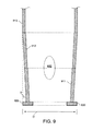
- FIG. 9 illustrates a cross-sectional view of the first few cans in the bottom section of an exemplary wind turbine tower, according to another aspect of the present invention.
- the first two cans 911 and 912 have a reverse taper profile.
- the thickness of the cans may decrease as the height increases.
- the side wall thickness of the first can 911 may be about 20 mm to about 50 mm
- the thickness of the second can 912 and third can 913 may be about 15 mm to about 50 mm.
- the angle ⁇ between a vertical line (the vertical dotted line in FIG. 9 ) and the side walls of cans 911 and 912 is about one to about five degrees. However, angles above and below this range could also be employed, as desired in the specific application.
- FIG. 10 illustrates a cross-sectional view of a wind turbine tower 1000, according to an aspect of the present invention.
- the tower 1000 may be comprised of three main sections, a bottom section 1031, middle section 1032 and top section 1033.
- Each main section may be comprised of a plurality of individual cylindrical cans, which are typically a cylinder of rolled steel.
- the tower sections may be fabricated as one integral item or from a plurality of individual sections.
- Bottom section 1031 in this example, contains at least one reverse taper portion 1030.
- the thickness and diameter of the sections may vary, but the lower portions of the tower generally have a greater thickness than the higher tower portions. However, the thickness of each portion of tower 1000 may be selected for the specific application and can have any appropriate thickness.
- the angle between a vertical line and the side wall of reverse taper portion 1030 can be about one to about five degrees. However, angles above and below this range could also be employed, as desired in the specific application.
- the maximum diameter of the tower 1000 can be about 13 feet 6 inches ( ⁇ 4.1 m) or less. However, it is to be understood that diameters above and below this range could also be employed, as desired in the specific application.
- Various embodiments of the present invention provide a wind turbine tower having at least one reverse taper portion near the base of the tower that has an increasing diameter with increasing elevation. This reverse taper portion may be contained within one can, or may be distributed over two or more cans. In towers having a "non-can" type construction, the reverse taper may be located on the lower portion of the tower.
- FIG. 11 illustrates a cross-sectional view of a wind turbine tower 1100, according to an aspect of the present invention.
- the tower 1100 may be comprised of three main sections, a bottom section 1131, middle section 1132 and top section 1133.
- Bottom section 1131 in this example, contains at least one stepped portion 1130.
- the maximum diameter of the tower 1100 can be about 13 feet 6 inches ( ⁇ 4.1 m) or less. However, it is to be understood that diameters above and below this range could also be employed, as desired in the specific application.
- angled portion 1030 and stepped portion 1130 have been shown in the drawings. However, it is to be understood that any suitable shape could be employed for the reverse taper portion near the base of the tower.
- the reverse taper portion could have a straight, curved, compound curved or any other suitable shape.
- rail carriers permit items of a maximum weight, width, height and length.
- the tower can be sized to fit within these limitations.
- the weight of each tower section can be designed to be under about 140,000 lbs ( ⁇ 65,000 kg), or under any weight limit imposed by typical rail carriers or trucking companies.
- the width and height of each tower section can be designed to be under about 13 feet 6 inches ( ⁇ 4.1 meters), or under any height and/or width limit imposed by typical rail carriers.
- the length of each tower section can be designed to be under about 89 feet ( ⁇ 27 meters), or under any length limit imposed by typical rail carriers.
- Rail transport outside the U.S. is also constrained by similar considerations of weight, width, height and length, but with sizes specific to the locale. Accordingly, an improved tower has been provided that can be shipped by rail, enabling less costly transportation for large towers.
- a single train can transport many wind turbine towers, whereas at least three trucks were required to transport a single tower.
- the present invention was described in conjunction with a tower for a wind turbine; however, it is to be understood that the tower, according to aspects of the present invention, may be useful for any application needing elevated towers.
- the present invention could be applied to electrical utility power transmission wire towers, communication towers, on or off-shore wind turbine towers, lighthouses, fire monitoring towers, agricultural silos, residential or commercial applications, and any other application requiring a tower.
Applications Claiming Priority (1)
| Application Number | Priority Date | Filing Date | Title |
|---|---|---|---|
| US12/484,645 US20100132269A1 (en) | 2009-06-15 | 2009-06-15 | Rail-transportable wind turbine tower |
Publications (1)
| Publication Number | Publication Date |
|---|---|
| EP2278157A2 true EP2278157A2 (en) | 2011-01-26 |
Family
ID=42221526
Family Applications (1)
| Application Number | Title | Priority Date | Filing Date |
|---|---|---|---|
| EP10165034A Withdrawn EP2278157A2 (en) | 2009-06-15 | 2010-06-07 | Rail-transportable wind turbine tower |
Country Status (6)
| Country | Link |
|---|---|
| US (1) | US20100132269A1 (ja) |
| EP (1) | EP2278157A2 (ja) |
| JP (1) | JP2010285992A (ja) |
| CN (1) | CN101922420A (ja) |
| AU (1) | AU2010202491A1 (ja) |
| CA (1) | CA2707227A1 (ja) |
Cited By (1)
| Publication number | Priority date | Publication date | Assignee | Title |
|---|---|---|---|---|
| EP2692967A2 (de) | 2012-08-04 | 2014-02-05 | e.n.o. energy systems GmbH | Verfahren zum Errichten eines Turmes aus Stahl einer Windenergieanlage und Turm aus Stahl für eine Windenergieanlage |
Families Citing this family (11)
| Publication number | Priority date | Publication date | Assignee | Title |
|---|---|---|---|---|
| JP5667822B2 (ja) * | 2010-09-21 | 2015-02-12 | 株式会社日立製作所 | 風車タワー内の部品搭載構造 |
| CN102312599B (zh) * | 2011-04-07 | 2013-03-13 | 济南巨能铁塔制造有限公司 | 输电线路多棱钢管杆 |
| CN102312601B (zh) * | 2011-04-07 | 2013-03-13 | 济南巨能铁塔制造有限公司 | 输电线路钢管杆 |
| JP5756358B2 (ja) * | 2011-07-13 | 2015-07-29 | 株式会社日立製作所 | フランジ構造及び風力発電装置 |
| US9249784B2 (en) | 2011-08-30 | 2016-02-02 | Vestas Wind Systems A/S | Transition structure for a wind turbine tower |
| US20120137623A1 (en) * | 2011-10-05 | 2012-06-07 | Balaji Haridasu | Wind turbine tower section and method of assembling a wind turbine tower |
| EP2846041B1 (en) * | 2013-09-06 | 2018-01-17 | youWINenergy GmbH | Retrofitted wind turbine installation |
| EP2846040B1 (en) * | 2013-09-06 | 2018-03-21 | youWINenergy GmbH | Tower assembly for a wind turbine installation |
| EP3139037A1 (en) * | 2015-09-02 | 2017-03-08 | Siemens Aktiengesellschaft | Tower for a wind turbine with buttresses |
| CN110185584A (zh) * | 2019-05-05 | 2019-08-30 | 山东中车同力钢构有限公司 | 一种可快速生产的风电塔筒及风电塔筒的生产方法 |
| US11643836B2 (en) * | 2021-01-21 | 2023-05-09 | Mark A. Danaczko | Monolithic towers having support structures, and method of designing and assembling the same |
Family Cites Families (46)
| Publication number | Priority date | Publication date | Assignee | Title |
|---|---|---|---|---|
| US451755A (en) * | 1891-05-05 | Foe ftjenituee | ||
| US294343A (en) * | 1884-02-26 | Tower | ||
| US689387A (en) * | 1901-06-24 | 1901-12-24 | William B Crossland | Sectional electric light, telephone, or telegraph pole. |
| US1897373A (en) * | 1930-07-29 | 1933-02-14 | Blaw Knox Co | Wave antenna |
| US2027733A (en) * | 1933-08-07 | 1936-01-14 | Lapp Insulator Company Inc | Vertical mast wave antenna |
| US2593989A (en) * | 1946-08-01 | 1952-04-22 | Ashaway Line & Twine Mfg | Outrigger rod |
| US2630075A (en) * | 1949-11-28 | 1953-03-03 | Monorail Engineering And Const | Overhead monorail system |
| US2709975A (en) * | 1951-04-14 | 1955-06-07 | Parker Brooks O'c | Truss structure and supporting column |
| US2759332A (en) * | 1952-08-04 | 1956-08-21 | Pacific Union Metal Company | Concrete pile joint |
| US3199300A (en) * | 1961-05-22 | 1965-08-10 | Foundation Specialties Inc | Pile construction |
| US3312020A (en) * | 1964-05-08 | 1967-04-04 | Schuster Wilhelm | Collapsible columnar structure |
| US3557969A (en) * | 1967-04-06 | 1971-01-26 | Coles Krane Gmbh | Outrigger mast for crane |
| US3742662A (en) * | 1971-08-05 | 1973-07-03 | Hursh Jack E Millbrae | Shoring frame system |
| JPS4860435A (ja) * | 1971-11-30 | 1973-08-24 | ||
| US3812771A (en) * | 1971-12-21 | 1974-05-28 | Mitsubishi Heavy Ind Ltd | Steel-tower chimney |
| DE2422932A1 (de) * | 1974-05-11 | 1975-11-20 | Porsche Ag | Schwenkbares stuetzbein fuer eine bruecke |
| US3984962A (en) * | 1975-11-28 | 1976-10-12 | General Dynamics Corporation | Mast structure and composite structural fitting therefore |
| US4171597A (en) * | 1976-01-29 | 1979-10-23 | Coles Cranes Limited | Crane boom and telescopic section for it |
| US4334775A (en) * | 1980-04-03 | 1982-06-15 | Western Electric Co., Inc. | Method for dynamically determining the horizontal motion and twist of a microwave tower |
| US4694630A (en) * | 1986-02-03 | 1987-09-22 | Mcginnis Henry J | Tower and method of constructing a tower |
| US5319902A (en) * | 1991-06-12 | 1994-06-14 | A. Ahlstrom | Mass tower and method of making the same |
| US5237783A (en) * | 1991-10-15 | 1993-08-24 | Kline Iron & Steel Co., Inc. | Tower pod for communications equipment |
| US5581958A (en) * | 1995-01-27 | 1996-12-10 | Unr Industries, Inc. | Pole and cabinet structure for antenna-mounting at communications site |
| US5568709A (en) * | 1995-07-28 | 1996-10-29 | Steckler; Richard D. | Simulated decorative architectural columns and method of making the same |
| US6082767A (en) * | 1998-02-02 | 2000-07-04 | Bujold; Edward J. | Safety athletic pole |
| US6309143B1 (en) * | 1998-05-27 | 2001-10-30 | Stanley Merjan | Composite pile with tapering lower portion and method for driving pile into granular soil |
| EP1269016B1 (de) * | 2000-03-23 | 2005-11-30 | Dewind Technik GmbH | Turm für windenergieanlagen |
| US6532700B1 (en) * | 2000-11-09 | 2003-03-18 | Beaird Industries, Inc. | Flange with cut for wind tower |
| US6470645B1 (en) * | 2000-11-09 | 2002-10-29 | Beaird Industries, Inc. | Method for making and erecting a wind tower |
| US6948290B2 (en) * | 2000-12-13 | 2005-09-27 | Ritz Telecommunications, Inc. | System and method for increasing the load capacity and stability of guyed towers |
| US6668498B2 (en) * | 2000-12-13 | 2003-12-30 | Ritz Telecommunications, Inc. | System and method for supporting guyed towers having increased load capacity and stability |
| DK200200178A (da) * | 2002-02-06 | 2003-08-07 | Vestas Wind Sys As | Ophængningsmidler til vindturbinetårne |
| US6732906B2 (en) * | 2002-04-08 | 2004-05-11 | John I. Andersen | Tapered tower manufacturing method and apparatus |
| US7210882B2 (en) * | 2003-07-03 | 2007-05-01 | Vestas-American Wind Technology | System and process for transporting wind turbines |
| NZ548883A (en) * | 2004-02-04 | 2009-07-31 | Corus Staal Bv | Tower for a wind turbine, prefabricated metal wall part for use in a tower for a wind turbine and method for constructing a tower for a wind turbine |
| CA2495596A1 (en) * | 2005-02-07 | 2006-08-07 | Resin Systems Inc. | Method of modular pole construction and modular pole assembly |
| US7387497B2 (en) * | 2005-04-12 | 2008-06-17 | Cone Matthew D | Adapter |
| US7360340B2 (en) * | 2005-04-12 | 2008-04-22 | Grundman Curtis M | Means for securing the lower end of a wind turbine tower to a foundation |
| US7367780B2 (en) * | 2005-09-30 | 2008-05-06 | General Electric Company | System and method for driving a monopile for supporting an offshore wind turbine |
| US7735290B2 (en) * | 2005-10-13 | 2010-06-15 | General Electric Company | Wind turbine assembly tower |
| EP1974112B1 (en) * | 2006-01-17 | 2012-10-24 | Vestas Wind Systems A/S | A wind turbine tower, a wind turbine, a wind turbine tower elevator and a method for assembling a wind turbine tower |
| US8056296B2 (en) * | 2006-04-07 | 2011-11-15 | General Electric Company | Methods and apparatus for assembling wind turbine towers |
| US7530780B2 (en) * | 2006-05-22 | 2009-05-12 | General Electric Company | Method and apparatus for wind power foundation |
| US20080236073A1 (en) * | 2007-03-30 | 2008-10-02 | General Electric Company | Low cost rail-transportable wind turbine tower |
| CN101225717A (zh) * | 2007-08-03 | 2008-07-23 | 邵凯 | 大中型风力发电装置的塔架结构 |
| CN201133327Y (zh) * | 2007-11-09 | 2008-10-15 | 尤林 | 新型风力发电机 |
-
2009
- 2009-06-15 US US12/484,645 patent/US20100132269A1/en not_active Abandoned
-
2010
- 2010-06-07 EP EP10165034A patent/EP2278157A2/en not_active Withdrawn
- 2010-06-10 CA CA2707227A patent/CA2707227A1/en not_active Abandoned
- 2010-06-13 CN CN2010102135058A patent/CN101922420A/zh active Pending
- 2010-06-14 JP JP2010134634A patent/JP2010285992A/ja not_active Withdrawn
- 2010-06-15 AU AU2010202491A patent/AU2010202491A1/en not_active Abandoned
Non-Patent Citations (1)
| Title |
|---|
| None |
Cited By (2)
| Publication number | Priority date | Publication date | Assignee | Title |
|---|---|---|---|---|
| EP2692967A2 (de) | 2012-08-04 | 2014-02-05 | e.n.o. energy systems GmbH | Verfahren zum Errichten eines Turmes aus Stahl einer Windenergieanlage und Turm aus Stahl für eine Windenergieanlage |
| DE102012015489A1 (de) | 2012-08-04 | 2014-02-06 | E.N.O. Energy Systems Gmbh | Verfahren zum Errichten eines Turmes aus Stahl einer Windenergieanlage und Turm aus Stahl für eine Windenergieanlage |
Also Published As
| Publication number | Publication date |
|---|---|
| JP2010285992A (ja) | 2010-12-24 |
| US20100132269A1 (en) | 2010-06-03 |
| CA2707227A1 (en) | 2010-12-15 |
| AU2010202491A1 (en) | 2011-01-06 |
| CN101922420A (zh) | 2010-12-22 |
Similar Documents
| Publication | Publication Date | Title |
|---|---|---|
| EP2278157A2 (en) | Rail-transportable wind turbine tower | |
| AU2003212370B2 (en) | Method of constructing large towers for wind turbines | |
| US20080236073A1 (en) | Low cost rail-transportable wind turbine tower | |
| US8402718B2 (en) | Wind turbine installation | |
| US11319723B2 (en) | Stay cable for structures | |
| US8250833B2 (en) | Wind turbine tower and method for constructing a wind turbine tower | |
| AU2009202807A1 (en) | Wind turbine assembly with tower mount | |
| EP2317139A2 (en) | Transportable wind turbine tower | |
| US20170058549A1 (en) | Tower for a wind turbine with buttresses | |
| EP2189657A1 (en) | Off-shore wind turbine and method of erecting a wind turbine tower | |
| CN101602395A (zh) | 用于在运输船上运输风力涡轮机塔架段的系统和方法 | |
| EP2350454B1 (en) | Method of manufacturing a wind turbine tower structure | |
| DK2574772T3 (en) | The wind turbine tower | |
| US11971012B2 (en) | Tower section arrangement for a guyed tower of a wind turbine, guyed wind turbine tower, wind turbine and method for assembling a wind turbine | |
| KR102178764B1 (ko) | 타워구조물 및, 풍력타워 | |
| DK2350454T3 (en) | PROCEDURE FOR THE PREPARATION OF A WINDMILL TOWER STRUCTURE |
Legal Events
| Date | Code | Title | Description |
|---|---|---|---|
| PUAI | Public reference made under article 153(3) epc to a published international application that has entered the european phase |
Free format text: ORIGINAL CODE: 0009012 |
|
| AK | Designated contracting states |
Kind code of ref document: A2 Designated state(s): AL AT BE BG CH CY CZ DE DK EE ES FI FR GB GR HR HU IE IS IT LI LT LU LV MC MK MT NL NO PL PT RO SE SI SK SM TR |
|
| AX | Request for extension of the european patent |
Extension state: BA ME RS |
|
| STAA | Information on the status of an ep patent application or granted ep patent |
Free format text: STATUS: THE APPLICATION IS DEEMED TO BE WITHDRAWN |
|
| 18D | Application deemed to be withdrawn |
Effective date: 20140103 |