EP2278093A2 - Oberflächenmontierte Tür und Rahmen, insbesondere geeignet zum Schließen von inspizierbaren Wandaussparungen - Google Patents
Oberflächenmontierte Tür und Rahmen, insbesondere geeignet zum Schließen von inspizierbaren Wandaussparungen Download PDFInfo
- Publication number
- EP2278093A2 EP2278093A2 EP10166057A EP10166057A EP2278093A2 EP 2278093 A2 EP2278093 A2 EP 2278093A2 EP 10166057 A EP10166057 A EP 10166057A EP 10166057 A EP10166057 A EP 10166057A EP 2278093 A2 EP2278093 A2 EP 2278093A2
- Authority
- EP
- European Patent Office
- Prior art keywords
- frame
- door
- slots
- wall
- arms
- Prior art date
- Legal status (The legal status is an assumption and is not a legal conclusion. Google has not performed a legal analysis and makes no representation as to the accuracy of the status listed.)
- Withdrawn
Links
- XLYOFNOQVPJJNP-UHFFFAOYSA-N water Substances O XLYOFNOQVPJJNP-UHFFFAOYSA-N 0.000 claims abstract description 3
- 239000011800 void material Substances 0.000 claims description 2
- 230000002093 peripheral effect Effects 0.000 description 3
- 238000010276 construction Methods 0.000 description 1
- 230000007423 decrease Effects 0.000 description 1
- 239000002737 fuel gas Substances 0.000 description 1
- 230000006870 function Effects 0.000 description 1
- 239000007789 gas Substances 0.000 description 1
- 238000004519 manufacturing process Methods 0.000 description 1
- 239000000463 material Substances 0.000 description 1
- 230000013011 mating Effects 0.000 description 1
- 239000003973 paint Substances 0.000 description 1
- 230000003014 reinforcing effect Effects 0.000 description 1
- 230000035807 sensation Effects 0.000 description 1
- 238000004513 sizing Methods 0.000 description 1
- 239000012780 transparent material Substances 0.000 description 1
Images


Classifications
-
- E—FIXED CONSTRUCTIONS
- E04—BUILDING
- E04F—FINISHING WORK ON BUILDINGS, e.g. STAIRS, FLOORS
- E04F19/00—Other details of constructional parts for finishing work on buildings
- E04F19/08—Built-in cupboards; Masks of niches; Covers of holes enabling access to installations
-
- E—FIXED CONSTRUCTIONS
- E04—BUILDING
- E04F—FINISHING WORK ON BUILDINGS, e.g. STAIRS, FLOORS
- E04F19/00—Other details of constructional parts for finishing work on buildings
- E04F19/08—Built-in cupboards; Masks of niches; Covers of holes enabling access to installations
- E04F19/083—Covers with fixing means providing for snap locking
Definitions
- the invention relates to a surface-mounted door and frame made by injecting a plastic into a mould or from other suitable materials and which are particularly suitable for closing inspectable wall recesses containing the connections of electrical, telephonic, water or gas supplies installed in buildings.
- the innovation is concerned with improvements to Italian Patent No.
- 256,144 belonging to the present applicant which describes a frame and door for the aforesaid purposes, made for example by injecting a plastic into a mould, both pre-coloured to the desired colour, usually grey or brown, or having embossed surfaces that are easy to paint, in which said door is provided on one side with male L-profile T shaped arms connected at right angles to this door by their leg and which can be inserted into and articulated quickly and removably in corresponding hinge slots formed in the two long sides of a frame, if of rectangular shape, or on all four sides of this frame if of square shape.
- Said slots may for example be T shaped in plan view, are arranged transversely to the sides of the frame, and have their narrow part towards the outside of said frame.
- the frame has a front bezel which is placed against the wall, and which has, projecting from its rear surface, an annular ledge or collar which fits into the recess let into the wall and which is designed to be able to be fixed to the inside surfaces of this recess using wall plugs and screws or masonry anchors.
- This operation of fixing said inner annular ledge of the frame has been found to be complicated and neither easy nor quick to carry out.
- the innovation relates to improvements to the frame, to limit it fundamentally to the bezel only, and hence to simplify its manufacture and enable the cornice to be mounted by means of screws and wall plugs placed in holes cut directly into the visible surface of the wall which contains the inspectable recess that is to be closed by surface-mounting the present system.
- the holes for the wall plugs are easy and quick to make and the frame is flatter and lighter than in the prior art.
- the frame T comprises a bezel 1, which in the present example is square but which can be rectangular, which has rounded outer 101 and inner 201 corners, which is in the shape of a frustum of a pyramid and whose inner perimeter has a sunken ledge 301 connected to the outer bezel by a perpendicular wall 401.
- the ledge 301 has corner portions 301' and middle portions 301" which are coplanar with each other and on which the door S will bear (see below).
- the T-shaped hinge slots 4 In the corner regions 301' of the ledge 301, in a symmetrical arrangement, are the T-shaped hinge slots 4, their heads towards the inside opening of the frame and their legs extending as far as the lateral wall 401, which has, in line with the slits, windows 104 which occupy the full height of this wall and have outwardly diverging rounded ends 5 useful for the fitting of the door S (see below).
- the frame 1 may be made, for example, with an outside dimension of about 220 mm, but it should be understood that it can be made in any other size. If the frame 1 is rectangular, at least one of said hinge slots 4 may also be provided in a middle portion 301" of the ledge 301 characterized by having, on the inner perimeter and on each side, a curved middle concavity 6 where this ledge 301 has, on its underside, wedge-shaped projections 106 separated from each other where their relief is greatest by a void 7 whose function will be described later.
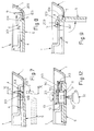
- the door S to be fitted to the frame T as described is illustrated in Figures 5 and 6 and is identical to that described in the patent cited in the introduction to this description.
- the door S comprises a square (or rectangular) closing panel 8 whose dimensions fit those of the inner bezel 301, 401 of the frame T. In the closed position the door S bears on the inner ledge 301, is circumscribed by the wall 401 of the frame T, and its outer face is approximately coplanar with that of the bezel 1.
- On the outer face of the panel 8 of the door S is a low peripheral edge 108 projecting a few tenths of a millimetre and smooth, while the rest of the outer surface of the panel 8 may be suitably embossed.
- the panel 8 On its inner face, the panel 8 has a projecting peripheral edge 208 which connects with longitudinal and transverse ribs 308 coplanar with said peripheral edge, forming for example a square (or rectangular) grid to improve the mechanical strength of the door S.
- the door S has L-profile hinge arms 9 integral laterally and perpendicularly with one of its sides (a long side if the door is rectangular), in a distribution corresponding to that of the hinge slots 4 in the frame T.
- each arm 9 is slightly greater in its free section than the thickness of the wall 401 of the frame T, its width is slightly less than the width of the foot portion of the hinge slots 4, and its position is such as to engage with the extension 104 of these slots occupying the wall 401 when the door S is in position, bearing on the inner ledge 301 via the side provided with the arms 9 and is displaced towards the bezel 1 as in the sequence of Figures 7 and 8 .
- the rounded ends 5 facilitate inserting the part 109 of the arm 9 underneath the bezel 1 ( Figure 8 ) to fix the door S to the frame T.
- the height of the head of the part 209 of the hinge arm 9 is conveniently greater than the width of the head of the slot 4 in order that as soon as the door is opened by rotation about the parts 109 of its lateral arms ( Figure 9 ), the head of said arms has a projection on the ledge 301 with dimensions such as to prevent it from being withdrawn from the head of the slots 4, so that the door S remains hinged to the frame T.
- the parts In order to remove the door S from the frame T, the parts have to be moved back to the positions shown in Figures 7 and 8 by means of which they were connected together. It will be obvious from Figure 9 that the rounded ends 5 are also useful for facilitating the opening rotation of the door S.
- Said areas G and G' may be provided with pieces of air gratings having fins oriented in contrary directions and diverging from each other towards the interior of the door and such as to oppose the passage of rainwater independently of whichever of the two short sides of the door is at the top.
- said areas G and G' can be provided with windows positioned for example on the inside surface in any way suitable for supporting, for example in such a way that they can be removed only from the inside, transparent infills, customized infills or air gratings, and these components can be fitted in a desired number, orientation and position, according to requirements.
- Figures 5, 6 and 12 show the door S can be locked in the closed position by a lock with a rotating barrel, of any suitable type, housed in a cylindrical seat 10 formed in the middle of the opposite side with the hinge arms 9. It has a collar 110 projecting from the inside face of the cover, further than the reinforcing grid 308.
- the seat 10 is characterized by an internal width which decreases towards the collar 110, allowing to house a rotating barrel 11 containing an axial seat 11 of prismatic section, open to the exterior, in which the mating shaft 112 of a turning key 12 can be engaged.
- this barrel On the inward end of this barrel are opposing hooked protrusions 211 onto which a bush 13 can be snapped via its hole 113 of prismatic plan view, allowing the bush 13 to revolve on the collar 110 and keeping the barrel 11 in position.
- Projecting radially from the bush 13 is a bolt 213, and that face of the latter which is towards the outside face of the cover has a protrusion 313 of e.g. spherical cap shape.
- the curved concavities 6 on the inner ledge 301 of the frame T are to avoid interference with said door S closing means 13, 110.
- the circular arc-shaped tracks 106 on the underside of the ledge 301, concentric with the cavities 6, are of such a size that when the bolt 213 is turned to the closed position, its spherical protrusion 313 is gradually lifted by said tracks 106 and snaps into position when it reaches the sunken middle part 7, thus giving the person closing the door the tactile and acoustic sensation that the bolt has reached the closed position.
- the lock illustrated can be replaced by a lock with a number key of standardized type easily available on the market, which can be allowed for when deciding the dimensions of the seat 10.
Landscapes
- Engineering & Computer Science (AREA)
- Architecture (AREA)
- Civil Engineering (AREA)
- Structural Engineering (AREA)
- Door And Window Frames Mounted To Openings (AREA)
- Securing Of Glass Panes Or The Like (AREA)
- Casings For Electric Apparatus (AREA)
Applications Claiming Priority (1)
| Application Number | Priority Date | Filing Date | Title |
|---|---|---|---|
| IT000050U ITBO20090050U1 (it) | 2009-06-23 | 2009-06-23 | Sportello con telaio a sovrapporre, particolarmente idonei per la chiusura di vani a muro ispezionabili. |
Publications (2)
| Publication Number | Publication Date |
|---|---|
| EP2278093A2 true EP2278093A2 (de) | 2011-01-26 |
| EP2278093A3 EP2278093A3 (de) | 2015-11-18 |
Family
ID=42734706
Family Applications (1)
| Application Number | Title | Priority Date | Filing Date |
|---|---|---|---|
| EP10166057.9A Withdrawn EP2278093A3 (de) | 2009-06-23 | 2010-06-15 | Oberflächenmontierte Tür und Rahmen, insbesondere geeignet zum Schließen von inspizierbaren Wandaussparungen |
Country Status (2)
| Country | Link |
|---|---|
| EP (1) | EP2278093A3 (de) |
| IT (1) | ITBO20090050U1 (de) |
Citations (1)
| Publication number | Priority date | Publication date | Assignee | Title |
|---|---|---|---|---|
| IT256144Y1 (it) | 2002-09-12 | 2004-04-13 | Eur Ex S R L | Sportello con telaio, in materia plastica, di uso facile e versatile,particolarmente per la chiusura dei vani a muro ispezionabili, contenenti le derivazioni delle reti elettriche, del telefono, dell'acqua o del gas poste a servizio degli edifici |
Family Cites Families (2)
| Publication number | Priority date | Publication date | Assignee | Title |
|---|---|---|---|---|
| US5653061A (en) * | 1996-01-05 | 1997-08-05 | Diversified Plastics, Inc. | Access panel |
| ATE528461T1 (de) * | 2007-02-22 | 2011-10-15 | Haco Spol S R O | System mit einem rahmen und einer lösbaren abdeckung für eine wand- oder deckenöffnung |
-
2009
- 2009-06-23 IT IT000050U patent/ITBO20090050U1/it unknown
-
2010
- 2010-06-15 EP EP10166057.9A patent/EP2278093A3/de not_active Withdrawn
Patent Citations (1)
| Publication number | Priority date | Publication date | Assignee | Title |
|---|---|---|---|---|
| IT256144Y1 (it) | 2002-09-12 | 2004-04-13 | Eur Ex S R L | Sportello con telaio, in materia plastica, di uso facile e versatile,particolarmente per la chiusura dei vani a muro ispezionabili, contenenti le derivazioni delle reti elettriche, del telefono, dell'acqua o del gas poste a servizio degli edifici |
Also Published As
| Publication number | Publication date |
|---|---|
| EP2278093A3 (de) | 2015-11-18 |
| ITBO20090050U1 (it) | 2010-12-24 |
Similar Documents
| Publication | Publication Date | Title |
|---|---|---|
| AU725658B2 (en) | Weatherproof padlock | |
| CA2714054C (en) | Enclosure for residential and commercial hydrants | |
| US8584271B2 (en) | Corner plate for holding a pool liner | |
| MX2008009492A (es) | Ensamble de cerradura. | |
| US5815996A (en) | Interior-mounted cover for roof ventilator | |
| EP2278093A2 (de) | Oberflächenmontierte Tür und Rahmen, insbesondere geeignet zum Schließen von inspizierbaren Wandaussparungen | |
| EP0225427A2 (de) | Scharnierzusammenstellung für Toilettendeckel | |
| US10258908B2 (en) | Filter module with window type clear bowl | |
| KR102372802B1 (ko) | 가변형 내부 프레임을 이용한 도어구조 | |
| EP0940510B1 (de) | Toiletteneinheit | |
| CN201474330U (zh) | 模块化的淋浴空间架构 | |
| US20040144045A1 (en) | Interior mounted cover having a breathable membrane for a roof ventilator | |
| EP1398439B1 (de) | Tür mit Rahmen aus Kunststoff zum Schliessen von überprüfbaren Wandaussparungen | |
| JP4410777B2 (ja) | 非表示型打掛錠の非常解錠構造 | |
| KR200444893Y1 (ko) | 우편함 | |
| EP2876221A1 (de) | Spülkasten mit einer austauschbaren Abdeckung | |
| KR20170137322A (ko) | 샤워 부스 | |
| CN210018949U (zh) | 一种电压力锅的开盖保险结构 | |
| US4817215A (en) | Toilets | |
| JPH0523513Y2 (de) | ||
| CN216266748U (zh) | 一种管道预留洞埋件 | |
| JP2583352Y2 (ja) | 鉄蓋用蝶番構造 | |
| JPH0235869Y2 (de) | ||
| CN201125613Y (zh) | 家用及办公用门系统及其连接装置 | |
| CN210797766U (zh) | 一种带有限制结构的拍盖排水阀 |
Legal Events
| Date | Code | Title | Description |
|---|---|---|---|
| PUAI | Public reference made under article 153(3) epc to a published international application that has entered the european phase |
Free format text: ORIGINAL CODE: 0009012 |
|
| AK | Designated contracting states |
Kind code of ref document: A2 Designated state(s): AL AT BE BG CH CY CZ DE DK EE ES FI FR GB GR HR HU IE IS IT LI LT LU LV MC MK MT NL NO PL PT RO SE SI SK SM TR |
|
| AX | Request for extension of the european patent |
Extension state: BA ME RS |
|
| PUAL | Search report despatched |
Free format text: ORIGINAL CODE: 0009013 |
|
| AK | Designated contracting states |
Kind code of ref document: A3 Designated state(s): AL AT BE BG CH CY CZ DE DK EE ES FI FR GB GR HR HU IE IS IT LI LT LU LV MC MK MT NL NO PL PT RO SE SI SK SM TR |
|
| AX | Request for extension of the european patent |
Extension state: BA ME RS |
|
| RIC1 | Information provided on ipc code assigned before grant |
Ipc: H02B 1/30 20060101ALN20151013BHEP Ipc: E06B 5/01 20060101ALN20151013BHEP Ipc: E04B 9/00 20060101ALI20151013BHEP Ipc: E04F 19/08 20060101AFI20151013BHEP |
|
| STAA | Information on the status of an ep patent application or granted ep patent |
Free format text: STATUS: THE APPLICATION IS DEEMED TO BE WITHDRAWN |
|
| 18D | Application deemed to be withdrawn |
Effective date: 20160519 |