EP2278092A2 - Modular system with connector for fixing wooden floor boards on joists - Google Patents
Modular system with connector for fixing wooden floor boards on joists Download PDFInfo
- Publication number
- EP2278092A2 EP2278092A2 EP10164458A EP10164458A EP2278092A2 EP 2278092 A2 EP2278092 A2 EP 2278092A2 EP 10164458 A EP10164458 A EP 10164458A EP 10164458 A EP10164458 A EP 10164458A EP 2278092 A2 EP2278092 A2 EP 2278092A2
- Authority
- EP
- European Patent Office
- Prior art keywords
- elements
- frame
- protrusions
- protrusion
- catch
- Prior art date
- Legal status (The legal status is an assumption and is not a legal conclusion. Google has not performed a legal analysis and makes no representation as to the accuracy of the status listed.)
- Withdrawn
Links
Images


Classifications
-
- E—FIXED CONSTRUCTIONS
- E04—BUILDING
- E04F—FINISHING WORK ON BUILDINGS, e.g. STAIRS, FLOORS
- E04F15/00—Flooring
- E04F15/02—Flooring or floor layers composed of a number of similar elements
- E04F15/04—Flooring or floor layers composed of a number of similar elements only of wood or with a top layer of wood, e.g. with wooden or metal connecting members
-
- E—FIXED CONSTRUCTIONS
- E04—BUILDING
- E04F—FINISHING WORK ON BUILDINGS, e.g. STAIRS, FLOORS
- E04F15/00—Flooring
- E04F15/02—Flooring or floor layers composed of a number of similar elements
- E04F15/02044—Separate elements for fastening to an underlayer
-
- E—FIXED CONSTRUCTIONS
- E04—BUILDING
- E04F—FINISHING WORK ON BUILDINGS, e.g. STAIRS, FLOORS
- E04F15/00—Flooring
- E04F15/02—Flooring or floor layers composed of a number of similar elements
- E04F15/02177—Floor elements for use at a specific location
- E04F15/02183—Floor elements for use at a specific location for outdoor use, e.g. in decks, patios, terraces, verandas or the like
-
- E—FIXED CONSTRUCTIONS
- E04—BUILDING
- E04F—FINISHING WORK ON BUILDINGS, e.g. STAIRS, FLOORS
- E04F15/00—Flooring
- E04F15/02—Flooring or floor layers composed of a number of similar elements
- E04F15/10—Flooring or floor layers composed of a number of similar elements of other materials, e.g. fibrous or chipped materials, organic plastics, magnesite tiles, hardboard, or with a top layer of other materials
-
- E—FIXED CONSTRUCTIONS
- E04—BUILDING
- E04F—FINISHING WORK ON BUILDINGS, e.g. STAIRS, FLOORS
- E04F15/00—Flooring
- E04F15/02—Flooring or floor layers composed of a number of similar elements
- E04F15/02044—Separate elements for fastening to an underlayer
- E04F2015/0205—Separate elements for fastening to an underlayer with load-supporting elongated furring elements between the flooring elements and the underlayer
- E04F2015/02066—Separate elements for fastening to an underlayer with load-supporting elongated furring elements between the flooring elements and the underlayer with additional fastening elements between furring elements and flooring elements
- E04F2015/02077—Separate elements for fastening to an underlayer with load-supporting elongated furring elements between the flooring elements and the underlayer with additional fastening elements between furring elements and flooring elements the additional fastening elements located in-between two adjacent flooring elements
- E04F2015/02094—Engaging side grooves running along the whole length of the flooring elements
Definitions
- Object of the invention is an assembling connector for fixing longitudinal finishing elements, particularly wooden floorboards and a modular system for fixing the longitudinal finishing elements.
- the connector finds applications in construction of a modular system of fixing longitudinal finishing elements particularly to the surface of e.g. terraces, summerhouses, garden alleys, swimming pools, garden ponds etc., settled on a base exposed to moisture or precipitation.
- the connector also finds application for fixing finishing facades i.e. longitudinal facade elements made of wood, plastics, wood-derived and wood-like materials or a combination of said materials.
- the connectors make it possible to build systems similar to siding-type facades, yet with a use of a modem pattern designing of any direction (horizontal, vertical etc.).
- Object of the invention is an assembling connector comprising a frame reinforced with ribbing, for fixing longitudinal finishing elements, exhibiting on side walls appropriate concave shaped elements integrated with catches located on the connector, characterised in that , it is equipped:
- the protrusions 13 and 13' are located in a direction perpendicular with respect to the protrusions 2 and 2'.
- the frame 1 is equipped with reinforcing ribbing having a form of elements 10, 11 and 11'.
- the frame 1 includes additionally ventilation and drainage elements in form of orifices 7 and 8 and indentations 12.
- Distance elements 5 are located on a wall of the frame having the protrusion 2.
- Object of the invention is also a modular system for fixing longitudinal finishing elements, characterised in that it includes longitudinal finishing elements and optionally longitudinal carrying elements and assembling connectors which are equipped:
- Protrusions 13 and 13' are located in a direction perpendicular with respect to protrusions 2 and 2'.
- the frame 1 is equipped with reinforcing ribbing having a form of elements 10, 11 and 11'.
- the frame 1 includes additionally elements to ensure ventilation and drainage, in a form of orifices 7 and 8 and indentations 12.
- Distance elements 5 are located on a wall frame having protrusion 2.
- finishing elements are floorboards or floor elements made of plastics and/or wood-like and/or wood-derived materials or wooden facade elements, made of plastics and/or wood-like materials and/or wood-derived materials, whereas the carrying elements are bars or slats made of wood, metal, plastics or wood-like and/or wood-derived materials.
- the connector and the system of the invention ensures easy and fast assembly of elements of floor or facades, e.g. floorboards, particularly terrace floorboards, on longitudinal carrying elements e.g. joists settled on a base (or on facades).
- the connector constitutes a repeated element of the modular system, which does not require separate fixing of all connectors with screws.
- the system is stable also in cases where only some of the connectors, preferably terminal ones, are fastened with screws to the base (or to joists or other carrying elements). Finishing elements of floors or facade elements, e.g. wooden boards, can be easily replaced, in case they are damaged or are fully disassembled e.g. in winter.
- Stabilising elements for the laid floor are the joists (subfloor or other longitudinal carrying elements) fastened in a conventional way, e.g. with screws, directly to a base/walls or other structural elements, e.g. side walls/bars of e.g. a terrace or a summerhouse construction.
- a base/walls or other structural elements e.g. side walls/bars of e.g. a terrace or a summerhouse construction.
- the connectors of the invention allow for fast assemble of terraces, summerhouses or recreational elements of seashore, having no permanent base or exhibiting an uneven base.
- These structures can also be mounted as "hanging" over a base through application of additional poles or bars, which can serve as carrying elements for joists.
- the joists can be separately levelled, independently from irregularities of the base.
- the connectors can be fixed not only directly on walls of the building or other vertical or skew structures, but also at some distance from facade surfaces to form optionally "clearance" between a facade surface - composed by means of the connectors of the invention - and a surface of building walls (the original facade).
- the connector of the invention and the system of the invention can have various uses in buildings and can be used for fixing longitudinal finishing elements of floors, walls, ceilings, or external facades.
- boards/bars/slats made of wood, plastics, metal, wood-like and wood-derived materials can be utilised. Combination of the above mentioned materials can also be used.
- fig. 1 shows the connector in a general view slantwise from above (from the side of finishing elements)
- fig. 2 shows a general view of the connector slantwise from bottom (from the side of carrying elements)
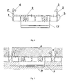
- fig. 3 shows the connector in a view from above
- fig. 4 shows a lateral cross section of the connector
- fig. 5 shows the connectors (one of it as a whole and two other in part) arranged with floor boards and carrying elements to show functioning of the whole system of arrangement of finishing elements of floors and facades
- fig. 6 shows a schematic view of floor (facade) upon assembling of finishing elements (two carrying elements are also shown, the connectors of the invention being marked in black).
- the connector of the invention is made of a rectangular frame 1, on opposite edges of which the protrusions 2 and 2' are located in parallel, the protrusion 2 being terminated with a perpendicular catch 3, whereas the protrusion 2' - with a hooked catch 4.
- the above-mentioned elements are located on a side, on which finishing elements of floors are to be fixed, i.e. from above.
- the connector is equipped with the parallel protrusions 13 and 13'. Structure of these elements and its principle of action is analogous to the that of the protrusions 2 and 2', although its spacing is narrower than that of the protrusions 2 and 2' located on edges of the connector.
- the protrusion 13 is terminated with a catch 14, the protrusion 13' - with a catch 15.
- protrusions 5 are located on a wall, on which the protrusion 2 is located.
- entilation and drainage orifices 7 and 8 and two assembling orifices 9 are located on an upper surface 6 of the connector.
- the connector is also provided with two large, symmetrically located, rectangular orifices 10 surrounded by side walls additionally reinforcing the connector structure. Inside the frame 1 reinforcing ribbing (walls) in a form of mutually rectangular elements 11 and 11' are also located. From the side of joists, the frame 1 on its edge is equipped with the indentations 12.
- the connector of the invention is equipped with a similar system of protrusions on both sides of the frame, i.e. at the side of carrying elements (joists) settled on the base and at the side of finishing floor elements.
- the joists in the system of the invention are narrower than finishing boards, therefore a span of protrusions 13 and 13' is smaller.
- the whole system must be moisture-resistant and permeable to air.
- the technical means used in a form of the orifices 7, 8 and 10 and the indentations 12 provide ventilation of the system and moisture flowing-away. Large orifices 10 make it possible to observe during assembling the joists co-working with the catches 14 and 15, which during assembling are located at the bottom of the connector.
- the assembling orifices 9 are located in all connectors, but it is not necessary to fasten all connectors with screws.
- Essence of the invention is fast assemble of individual elements of the system by means of catches, which make it possible to simply "snap-in” and “snap-out” - in the first stage - connectors to a structure of joists, and - in the second stage - finishing elements (boards) to the connectors.
- the snapping-in and snapping-out of elements is simplified thanks to a structure of catches.
- the floorboard is at first inserted into the connector at the side of the catch 3, and then it is pressed-in (by pressing the finishing element) at the side of the catch 4, until the catch acts as a lock through insertion to the longitudinal concave shaped element on floorboard side walls.
- the connectors of the invention "co-work” with finishing elements of floors or facades through application of specifically shaped protrusions 2, 2', 13 and 13' and locks 3, 4, 14 and 15, which was schematically presented on fig. 5 .
- Finishing elements "A” are equipped with longitudinal shaped elements "a” fitted to dimensions of the protrusions 2 and 2', and the protrusions 3 and 4.
- Carrying elements "B” are equipped with shaped elements "b”.
- the modular system of the invention can be adapted to match any finishing and carrying elements, which can also be adapted to size of connectors, depending on particular need.
Landscapes
- Engineering & Computer Science (AREA)
- Architecture (AREA)
- Civil Engineering (AREA)
- Structural Engineering (AREA)
- Life Sciences & Earth Sciences (AREA)
- Wood Science & Technology (AREA)
- Floor Finish (AREA)
Abstract
- at the side of finishing elements with parallel protrusions 2 and 2' located on edges of the frame 1 perpendicularly to its surface, the protrusion 2 being terminated with a hooked catch 3, and the protrusion 2' with a perpendicular catch 4,
- at the side of carrying elements with parallel protrusions 13 and 13', also perpendicular to the surface of frame 1, the protrusion 13 being terminated with a hooked catch 14, and the protrusion 13' - with a perpendicular catch 15, the protrusions 13 and 13' and catches 14 and 15 being integrated with the carrying elements exhibiting appropriate concave shaped elements on side walls.
- with distance protrusions 5 located on a side wall of the frame 1.
Description
- Object of the invention is an assembling connector for fixing longitudinal finishing elements, particularly wooden floorboards and a modular system for fixing the longitudinal finishing elements. The connector finds applications in construction of a modular system of fixing longitudinal finishing elements particularly to the surface of e.g. terraces, summerhouses, garden alleys, swimming pools, garden ponds etc., settled on a base exposed to moisture or precipitation. The connector also finds application for fixing finishing facades i.e. longitudinal facade elements made of wood, plastics, wood-derived and wood-like materials or a combination of said materials. The connectors make it possible to build systems similar to siding-type facades, yet with a use of a modem pattern designing of any direction (horizontal, vertical etc.).
- From European Patent
EP1306485 , a modular system of ground beams for arrangement of pavement elements and other surfaces of that type, which can be inter alia made of wood, is known. The system has a form of a network consisting of elements arranged on a base and individual segments that fix walkway tiles. Subsequent segments are joined with vertical locks, which consolidate subsequent segments of a surface and provide gaps between them, through which moisture can flow down. - Object of the invention is an assembling connector comprising a frame reinforced with ribbing, for fixing longitudinal finishing elements, exhibiting on side walls appropriate concave shaped elements integrated with catches located on the connector, characterised in that, it is equipped:
- at the side of finishing elements with
parallel protrusions 2 and 2' located on edges offrame 1 perpendicularly to its surface, the protrusion 2' being terminated with ahooked catch 4, and theprotrusion 2 with aperpendicular catch 3, - at the side of carrying elements with
parallel protrusions 13 and 13', also perpendicular to the surface offrame 1, theprotrusion 13 being terminated with ahooked catch 14, and the protrusion 13' with aperpendicular catch 15, theprotrusions 13 and 13', and catches 14 and 15 being integrated with the carrying elements exhibiting appropriate concave shaped elements on side walls. - with
distance protrusions 5 located on a side wall of theframe 1. - The
protrusions 13 and 13' are located in a direction perpendicular with respect to theprotrusions 2 and 2'. - The
frame 1 is equipped with reinforcing ribbing having a form ofelements - The
frame 1 includes additionally ventilation and drainage elements in form oforifices indentations 12. -
Distance elements 5 are located on a wall of the frame having theprotrusion 2. - Object of the invention is also a modular system for fixing longitudinal finishing elements, characterised in that it includes longitudinal finishing elements and optionally longitudinal carrying elements and assembling connectors which are equipped:
- at the side of finishing elements with the
parallel protrusions 2 and 2' located on edges of theframe 1 perpendicularly to its surface, the protrusion 2' being terminated with ahooked catch 4, and theprotrusion 2 with aperpendicular catch 3, - at the side of carrying elements with the
parallel protrusions 13 and 13', also perpendicular to the surface of theframe 1, theprotrusion 13 being terminated with ahooked catch 14, and the protrusion 13' with aperpendicular catch 15, theprotrusions 13 and 13', and thecatches - with
distance protrusions 5 located on a side wall of theframe 1. -
Protrusions 13 and 13' are located in a direction perpendicular with respect toprotrusions 2 and 2'. - The
frame 1 is equipped with reinforcing ribbing having a form ofelements - The
frame 1 includes additionally elements to ensure ventilation and drainage, in a form oforifices indentations 12. -
Distance elements 5 are located on a wallframe having protrusion 2. Preferably, finishing elements are floorboards or floor elements made of plastics and/or wood-like and/or wood-derived materials or wooden facade elements, made of plastics and/or wood-like materials and/or wood-derived materials, whereas the carrying elements are bars or slats made of wood, metal, plastics or wood-like and/or wood-derived materials. - The connector and the system of the invention ensures easy and fast assembly of elements of floor or facades, e.g. floorboards, particularly terrace floorboards, on longitudinal carrying elements e.g. joists settled on a base (or on facades). Through mutual perpendicular arrangement of carrying elements and finishing elements, the whole structure is stable and durable. The connector constitutes a repeated element of the modular system, which does not require separate fixing of all connectors with screws. The system is stable also in cases where only some of the connectors, preferably terminal ones, are fastened with screws to the base (or to joists or other carrying elements). Finishing elements of floors or facade elements, e.g. wooden boards, can be easily replaced, in case they are damaged or are fully disassembled e.g. in winter. Stabilising elements for the laid floor are the joists (subfloor or other longitudinal carrying elements) fastened in a conventional way, e.g. with screws, directly to a base/walls or other structural elements, e.g. side walls/bars of e.g. a terrace or a summerhouse construction. By fixing several joists it is possible to lay the whole floor and thanks to connectors, the floor elements are fixed in ideally equal interspaces and form aesthetic and even surface. The connectors of the invention allow for fast assemble of terraces, summerhouses or recreational elements of seashore, having no permanent base or exhibiting an uneven base. These structures can also be mounted as "hanging" over a base through application of additional poles or bars, which can serve as carrying elements for joists. The joists can be separately levelled, independently from irregularities of the base. Similarly, in case of facade elements - the connectors can be fixed not only directly on walls of the building or other vertical or skew structures, but also at some distance from facade surfaces to form optionally "clearance" between a facade surface - composed by means of the connectors of the invention - and a surface of building walls (the original facade).
- Thanks to its universal nature, the connector of the invention and the system of the invention can have various uses in buildings and can be used for fixing longitudinal finishing elements of floors, walls, ceilings, or external facades. For manufacturing of finishing elements and carrying elements, boards/bars/slats made of wood, plastics, metal, wood-like and wood-derived materials can be utilised. Combination of the above mentioned materials can also be used.
- Object of the invention is shown in an example of embodiment on a drawing, on which
fig. 1 shows the connector in a general view slantwise from above (from the side of finishing elements),fig. 2 shows a general view of the connector slantwise from bottom (from the side of carrying elements),fig. 3 shows the connector in a view from above,fig. 4 shows a lateral cross section of the connector,fig. 5 shows the connectors (one of it as a whole and two other in part) arranged with floor boards and carrying elements to show functioning of the whole system of arrangement of finishing elements of floors and facades, andfig. 6 shows a schematic view of floor (facade) upon assembling of finishing elements (two carrying elements are also shown, the connectors of the invention being marked in black). - The connector of the invention is made of a
rectangular frame 1, on opposite edges of which theprotrusions 2 and 2' are located in parallel, theprotrusion 2 being terminated with aperpendicular catch 3, whereas the protrusion 2' - with ahooked catch 4. The above-mentioned elements are located on a side, on which finishing elements of floors are to be fixed, i.e. from above. At the side of the base, i.e. the side of joists, the connector is equipped with theparallel protrusions 13 and 13'. Structure of these elements and its principle of action is analogous to the that of theprotrusions 2 and 2', although its spacing is narrower than that of theprotrusions 2 and 2' located on edges of the connector. Theprotrusion 13 is terminated with acatch 14, the protrusion 13' - with acatch 15. On a side wall of theframe 1,distance protrusions 5 are located. They are located on a wall, on which theprotrusion 2 is located. On anupper surface 6 of the connector, entilation anddrainage orifices orifices 9 are located. The connector is also provided with two large, symmetrically located,rectangular orifices 10 surrounded by side walls additionally reinforcing the connector structure. Inside theframe 1 reinforcing ribbing (walls) in a form of mutuallyrectangular elements 11 and 11' are also located. From the side of joists, theframe 1 on its edge is equipped with theindentations 12. - The connector of the invention is equipped with a similar system of protrusions on both sides of the frame, i.e. at the side of carrying elements (joists) settled on the base and at the side of finishing floor elements. The joists in the system of the invention are narrower than finishing boards, therefore a span of
protrusions 13 and 13' is smaller. The whole system must be moisture-resistant and permeable to air. The technical means used in a form of theorifices indentations 12 provide ventilation of the system and moisture flowing-away.Large orifices 10 make it possible to observe during assembling the joists co-working with thecatches orifices 9 are located in all connectors, but it is not necessary to fasten all connectors with screws. Essence of the invention is fast assemble of individual elements of the system by means of catches, which make it possible to simply "snap-in" and "snap-out" - in the first stage - connectors to a structure of joists, and - in the second stage - finishing elements (boards) to the connectors. The snapping-in and snapping-out of elements is simplified thanks to a structure of catches. The floorboard is at first inserted into the connector at the side of thecatch 3, and then it is pressed-in (by pressing the finishing element) at the side of thecatch 4, until the catch acts as a lock through insertion to the longitudinal concave shaped element on floorboard side walls. - The connectors of the invention "co-work" with finishing elements of floors or facades through application of specifically
shaped protrusions locks fig. 5 . Finishing elements "A" are equipped with longitudinal shaped elements "a" fitted to dimensions of theprotrusions 2 and 2', and theprotrusions - Through a change in a size of the
protrusions
Claims (11)
- Assembling connector including a frame reinforced with ribbing, for fixing longitudinal finishing elements having on their side walls appropriate concave shaped elements integrated with catches located on the connector, characterised in that it is equipped:- at the side of finishing elements with parallel protrusions (2) and (2') located on edges of the frame (1) perpendicularly to its surface, the protrusion (2') being terminated with a hooked catch (4), and the protrusion (2) - with a perpendicular catch (3),- at the side of carrying elements with parallel protrusions (13) and (13'), also perpendicular to the surface of the frame (1), the protrusion (13) being terminated with a hooked catch (14), and the protrusion (13') with a perpendicular catch (15), and the protrusions (13) and (13') and catches (14) and (15) are integrated with carrying elements exhibiting appropriate concave shaped elements on side walls.- with distance protrusions (5) located on a side wall of the frame (1).
- Connector according to claim 1, characterised in that, the protrusions (13) and (13') are located in a direction perpendicular with respect to the protrusions (2) and (2').
- Connector according to claim 1, characterised in that the frame (1) is equipped with reinforcing ribbing having a form of elements (10), (11) and (11').
- Connector according to claim 1, characterised in that the frame (1) additionally comprises ventilation and drainage elements in form of orifices (7) and (8) and indentations (12).
- Connector according to claim 1, characterised in that the distance elements (5) are located on a wall of the frame having the protrusion (2).
- Modular system for fixing longitudinal finishing elements, characterised in that it includes longitudinal finishing elements and optionally longitudinal carrying elements and assembling connectors equipped:- at the side of finishing elements - with parallel protrusions (2) and (2') located on edges of frame (1) perpendicularly to its surface, the protrusion (2') being terminated with a hooked catch (4), and the protrusion (2) - with a perpendicular catch (3),- at the side of carrying elements with parallel protrusions (13) and (13'), also perpendicular to the surface of frame (1), the protrusion (13) being terminated with a hooked catch (14), and the protrusion (13') - with a perpendicular catch (15), the protrusions (13) and (13') and the catches (14) and (15) are integrated with the carrying elements exhibiting appropriate concave shaped elements on side walls.- with distance protrusions (5) located on a side wall of the frame (1).
- System according to claim 6, characterised in that the protrusions (13) and (13') are located in a direction perpendicular with respect to the protrusions (2) and (2').
- System according to claim 6, characterised in that the frame (1) is equipped with reinforcing ribbing having a form of the elements (10), (11) and (11').
- System according to claim 6, characterised in that the frame (1) additionally includes ventilation and drainage elements in form of orifices (7) and (8) and indentations (12).
- System according to claim 6, characterised in that the distance elements (5) are located on a wall frame having the protrusion (2).
- System according to claim 6, characterised in that the finishing elements are floorboards or floor elements made of plastics and/or wood-like and/or wood-derived materials or facade elements made of wood, plastics and/or wood-like and/or wood-derived materials, and the carrying elements are bars or slats made of wood, metal, plastics or wood-like and/or wood-derived materials.
Applications Claiming Priority (1)
| Application Number | Priority Date | Filing Date | Title |
|---|---|---|---|
| PL388172A PL221358B1 (en) | 2009-06-02 | 2009-06-02 | Assembly connector for mounting longitudinal finishing elements, especially wooden floorboards and a modular system for mounting longitudinal finishing elements |
Related Parent Applications (1)
| Application Number | Title | Priority Date | Filing Date |
|---|---|---|---|
| PL38817209 Previously-Filed-Application | 2009-06-02 |
Publications (2)
| Publication Number | Publication Date |
|---|---|
| EP2278092A2 true EP2278092A2 (en) | 2011-01-26 |
| EP2278092A3 EP2278092A3 (en) | 2016-04-27 |
Family
ID=43302608
Family Applications (1)
| Application Number | Title | Priority Date | Filing Date |
|---|---|---|---|
| EP10164458.1A Withdrawn EP2278092A3 (en) | 2009-06-02 | 2010-05-31 | Modular system with connector for fixing wooden floor boards on joists |
Country Status (2)
| Country | Link |
|---|---|
| EP (1) | EP2278092A3 (en) |
| PL (1) | PL221358B1 (en) |
Cited By (2)
| Publication number | Priority date | Publication date | Assignee | Title |
|---|---|---|---|---|
| US9062463B2 (en) | 2012-12-04 | 2015-06-23 | Adam CHOJNOWSKI | Construction set for covering substrate, in particular floor substrate |
| CN105649301A (en) * | 2016-03-18 | 2016-06-08 | 蒋伟平 | Outdoor floor protection unit and mounting mechanism |
Citations (1)
| Publication number | Priority date | Publication date | Assignee | Title |
|---|---|---|---|---|
| EP1306485A1 (en) | 2001-10-23 | 2003-05-02 | Prati Group S.r.l | Modular removable supports for pavements |
Family Cites Families (4)
| Publication number | Priority date | Publication date | Assignee | Title |
|---|---|---|---|---|
| US5394667A (en) * | 1993-03-01 | 1995-03-07 | Nystrom; Ron | Flooring construction and method |
| DE102004032783A1 (en) * | 2004-07-06 | 2006-02-16 | Conradi + Kaiser Gmbh | Plate for the formation of a covering, in particular for outdoor use, and covering |
| ITNA20040045A1 (en) * | 2004-07-30 | 2004-10-30 | Giovanni Iovene | INTERLOCKING OR SLIDING SYSTEM FOR LAYING WOODEN FLOORS FOR EXTERIORS AND INTERIORS. |
| ITRE20070066A1 (en) * | 2007-05-11 | 2008-11-12 | Prati Group Sparenato | REMOVABLE SUPPORTS FOR OUTDOOR AND / OR INTERNAL FLOORS |
-
2009
- 2009-06-02 PL PL388172A patent/PL221358B1/en unknown
-
2010
- 2010-05-31 EP EP10164458.1A patent/EP2278092A3/en not_active Withdrawn
Patent Citations (1)
| Publication number | Priority date | Publication date | Assignee | Title |
|---|---|---|---|---|
| EP1306485A1 (en) | 2001-10-23 | 2003-05-02 | Prati Group S.r.l | Modular removable supports for pavements |
Cited By (3)
| Publication number | Priority date | Publication date | Assignee | Title |
|---|---|---|---|---|
| US9062463B2 (en) | 2012-12-04 | 2015-06-23 | Adam CHOJNOWSKI | Construction set for covering substrate, in particular floor substrate |
| CN105649301A (en) * | 2016-03-18 | 2016-06-08 | 蒋伟平 | Outdoor floor protection unit and mounting mechanism |
| CN105649301B (en) * | 2016-03-18 | 2017-12-08 | 蒋伟平 | A kind of outdoor flooring installation unit and installing mechanism |
Also Published As
| Publication number | Publication date |
|---|---|
| PL221358B1 (en) | 2016-03-31 |
| EP2278092A3 (en) | 2016-04-27 |
| PL388172A1 (en) | 2010-12-06 |
Similar Documents
| Publication | Publication Date | Title |
|---|---|---|
| US20070151190A1 (en) | Thin stone or thin brick veneer wall system and clips therefor | |
| US7571576B2 (en) | Decking system | |
| AU2012280201B2 (en) | Fastening system | |
| US7621089B2 (en) | Prefabricated modular building component and method of use | |
| US20090013639A1 (en) | Modular Building Structure | |
| EP3284877A1 (en) | Ventilated façade | |
| EP1766155B1 (en) | Construction system for constructing plane structures | |
| KR102087547B1 (en) | Deck road system using composite materials and method of installing thereof | |
| US20100058692A1 (en) | Caisson ceiling system | |
| EP2278092A2 (en) | Modular system with connector for fixing wooden floor boards on joists | |
| KR20100056595A (en) | Construction materials deck assembly | |
| US9644326B1 (en) | Monolithic paver | |
| US8065840B2 (en) | Modular building construction system and method of constructing | |
| KR101347155B1 (en) | Wood block for architecture | |
| JP6752581B2 (en) | Curtain board mounting structure of floor structure and construction method of floor structure | |
| JP6734064B2 (en) | Floor structure and construction method of floor structure | |
| KR200423523Y1 (en) | Deck tile | |
| JP4355065B2 (en) | Entrance porch installation structure | |
| US20240110390A1 (en) | System and method for decking tiles | |
| RU79596U1 (en) | COATING | |
| EP1760219B1 (en) | Mounting system for floor with tiles | |
| JP3054472U (en) | Terrace deck | |
| KR20230157060A (en) | Finishing materials for architecture | |
| DE102013021650A1 (en) | channel base | |
| RU78242U1 (en) | WOOD FLOOR DESIGNS, FASTENING ELEMENT AND WOODEN BOARD FOR HIM |
Legal Events
| Date | Code | Title | Description |
|---|---|---|---|
| PUAI | Public reference made under article 153(3) epc to a published international application that has entered the european phase |
Free format text: ORIGINAL CODE: 0009012 |
|
| AK | Designated contracting states |
Kind code of ref document: A2 Designated state(s): AL AT BE BG CH CY CZ DE DK EE ES FI FR GB GR HR HU IE IS IT LI LT LU LV MC MK MT NL NO PL PT RO SE SI SK SM TR |
|
| AX | Request for extension of the european patent |
Extension state: BA ME RS |
|
| PUAL | Search report despatched |
Free format text: ORIGINAL CODE: 0009013 |
|
| AK | Designated contracting states |
Kind code of ref document: A3 Designated state(s): AL AT BE BG CH CY CZ DE DK EE ES FI FR GB GR HR HU IE IS IT LI LT LU LV MC MK MT NL NO PL PT RO SE SI SK SM TR |
|
| AX | Request for extension of the european patent |
Extension state: BA ME RS |
|
| RIC1 | Information provided on ipc code assigned before grant |
Ipc: E04F 15/02 20060101ALI20160318BHEP Ipc: E04F 15/04 20060101AFI20160318BHEP Ipc: E04F 15/10 20060101ALI20160318BHEP |
|
| STAA | Information on the status of an ep patent application or granted ep patent |
Free format text: STATUS: THE APPLICATION IS DEEMED TO BE WITHDRAWN |
|
| 18D | Application deemed to be withdrawn |
Effective date: 20161028 |