EP2277655A1 - Procédé et dispositif destiné au soudage 'keyhole' par plasma avec modification de l'écoulment volumique et/ou de la composition du gaz en fonction de conditions limites du procédé de soudage - Google Patents
Procédé et dispositif destiné au soudage 'keyhole' par plasma avec modification de l'écoulment volumique et/ou de la composition du gaz en fonction de conditions limites du procédé de soudage Download PDFInfo
- Publication number
- EP2277655A1 EP2277655A1 EP09013534A EP09013534A EP2277655A1 EP 2277655 A1 EP2277655 A1 EP 2277655A1 EP 09013534 A EP09013534 A EP 09013534A EP 09013534 A EP09013534 A EP 09013534A EP 2277655 A1 EP2277655 A1 EP 2277655A1
- Authority
- EP
- European Patent Office
- Prior art keywords
- gas
- welding
- volume flow
- composition
- plasma
- Prior art date
- Legal status (The legal status is an assumption and is not a legal conclusion. Google has not performed a legal analysis and makes no representation as to the accuracy of the status listed.)
- Granted
Links
Images


Classifications
-
- B—PERFORMING OPERATIONS; TRANSPORTING
- B23—MACHINE TOOLS; METAL-WORKING NOT OTHERWISE PROVIDED FOR
- B23K—SOLDERING OR UNSOLDERING; WELDING; CLADDING OR PLATING BY SOLDERING OR WELDING; CUTTING BY APPLYING HEAT LOCALLY, e.g. FLAME CUTTING; WORKING BY LASER BEAM
- B23K10/00—Welding or cutting by means of a plasma
- B23K10/02—Plasma welding
-
- B—PERFORMING OPERATIONS; TRANSPORTING
- B23—MACHINE TOOLS; METAL-WORKING NOT OTHERWISE PROVIDED FOR
- B23K—SOLDERING OR UNSOLDERING; WELDING; CLADDING OR PLATING BY SOLDERING OR WELDING; CUTTING BY APPLYING HEAT LOCALLY, e.g. FLAME CUTTING; WORKING BY LASER BEAM
- B23K10/00—Welding or cutting by means of a plasma
- B23K10/006—Control circuits therefor
-
- B—PERFORMING OPERATIONS; TRANSPORTING
- B23—MACHINE TOOLS; METAL-WORKING NOT OTHERWISE PROVIDED FOR
- B23K—SOLDERING OR UNSOLDERING; WELDING; CLADDING OR PLATING BY SOLDERING OR WELDING; CUTTING BY APPLYING HEAT LOCALLY, e.g. FLAME CUTTING; WORKING BY LASER BEAM
- B23K9/00—Arc welding or cutting
- B23K9/16—Arc welding or cutting making use of shielding gas
- B23K9/167—Arc welding or cutting making use of shielding gas and of a non-consumable electrode
Definitions
- the present invention relates to a method for plasma needle hole welding of a workpiece using at least one process gas, wherein the gas composition and / or at least one gas volume flow of the process gas are changed over time, and a corresponding device.
- Welding refers to the cohesive joining of components using heat and / or pressure, optionally using welding consumables.
- welding consumables for metals, but also in the welding of glass or for thermoplastics usually fusion welding processes are used. Fusion welding usually involves welding with localized melt flow without application of force and thus without pressure.
- the connection of the components is usually in the form of welds or points.
- Plasma welding is one of the tungsten inert gas (WP) Processes in which a plasma jet serves as a heat source.
- the plasma jet is generated by ionization and constriction of an arc, directed at a workpiece and, for example, moved along a desired weld path. Due to the constriction of the plasma jet to an almost cylindrical gas column (usually by a water-cooled copper nozzle, usually with the aid of a so-called focusing gas) results in a higher energy concentration than conventional welding methods, such as TIG welding.
- a plasma torch surrounding the electrode concentric nozzles up to three gases or gas mixtures can be supplied, including the plasma gas, the focusing gas for constricting the plasma jet and the inert gas.
- the plasma jet and the focusing gas are enveloped by inert gas.
- the use of protective gas serves to protect the melt from oxidation during the welding process.
- Plasma welding is a welding process in which a constricted Arc is used.
- arc-transferred plasma arc welding the arc burns between the non-consumable electrode and the workpiece. The constriction of the arc higher energy densities are achieved than in conventional arc welding with non-consumable electrode, the so-called TIG welding.
- the plasma taphole welding represents a variant of the plasma welding.
- As a high-performance welding process it allows the processing of larger sheet thicknesses with low thermal distortion and high welding speeds and is currently used mainly for the welding joining of chromium-nickel steels.
- this technique is used today if special demands are placed on the quality of the weld with regard to penetration, seam shape and seam appearance. It is usually used up to a sheet thickness of 8 to 10 mm.
- the main areas of application are chemical plant construction, the aerospace industry and container and pipeline construction.
- the plasma jet passes through the entire workpiece thickness at the beginning of the welding process. In this case, the molten bath resulting from the melting of the workpiece is pushed aside by the plasma jet. The surface tension of the melt prevents falling through the stitch hole. Instead, the melt flows back behind the forming welding eyelet and solidifies to the weld.
- plasma keyhole welding As with plasma welding, up to three gas streams are used as process gases. Inside is the plasma gas. Due to the high energy density inside the plasma gas forms the plasma jet. The Plamagas is usually surrounded by a protective gas, which has the main task of protecting the plasma jet and processing site from undesirable effects from the environment. Furthermore, in many cases, a so-called focusing gas is used, which supports the constriction and orientation of the plasma jet and which is normally performed between plasma and inert gas.
- An indispensable prerequisite for the use of plasma taphole welding is the process-reliable design of the stitch hole.
- an exact, associated with high time, exact edge preparation and a corresponding positioning of the components and the exact compliance with the welding parameters are a prerequisite.
- deviations from these boundary conditions e.g. Due to variable gaps and edge offsets as well as jumps in geometry, which cause a variable heat dissipation into the component, insufficient penetration welding, spatter formation, occurrence of penetration marks or sagging of the weld pool can occur.
- these process instabilities also occur more frequently due to strong variations in the chemical composition (alloy) as well as a low surface tension and viscosity.
- the brightness of the passing plasma jet, the pressure resulting from its kinetic energy, and / or the electrical conductivity of its part (so-called penetrating flow) on the back of the workpiece can be used as the control variable of the through-welding.
- the stitch hole formation is then kept constant via a variation of the welding current.
- the welding current is usually set to a basic level, and can be increased if necessary to an increased value (pulse level) in order to supply more energy to the component.
- the thermal load capacity of the plasma gas nozzle limits the maximum welding current, the performance of the plasma torch in the basic current phase can not be fully exploited because a "reserve" for the pulse level must be provided in each case.
- JP 08039259 A a method of periodically varying the plasma gas in plasma and plasma keyhole welding in pulsed mode.
- a periodic change in the composition of the protective gas during welding by changing at least one volumetric flow discloses the US 3484575 A .
- the DE 102007017223 A1 and the DE 102007017224 A1 disclose methods for plasma taphole welding, wherein in each case a gas mixture is used as the plasma gas and / or as a protective gas. At least one gas composition or at least one gas volume flow are changed over time several times during the welding process, as a result of which a time-varying dynamic pressure is exerted on the melt, causing it to vibrate accordingly. As a result, the process stability increases when the melt merges behind the tap hole and the kinematics of the stitch hole formation is advantageously changed.
- the energy density of the plasma jet can be varied by the temporally variable composition or the time-varying gas volume flow of the focusing gas.
- the present invention is therefore based on the object of providing a method and a device for plasma needle punch welding, by which the process stability and handling, in particular the stability of the tap hole formation, are improved and / or the maximum achievable welding speed is increased ,
- this object is achieved in that, in a method for plasma needle hole welding of a workpiece using at least one process gas, wherein the gas composition and / or at least one gas volume flow of the process gas are changed over time, the gas volume flow and / or the gas composition of at least one process gas during a welding operation in dependence on at least one boundary condition of the welding operation to be temporally changed.
- process gas is understood to mean one of the gases used in plasma stitchhole welding, such as a plasma gas, a focusing gas and / or an inert gas or forming gas.
- a "temporal change" of the gas composition and / or the gas volume flow comprises in particular a stepwise, continuous and / or writable by a mathematical function increase, decrease and / or modulation, in particular also a periodic change of a component of a gas composition.
- the frequency, phase, amplitude and / or baseline of a periodically changing gas composition and / or a periodically changing gas volume flow may be changed due to changing boundary conditions.
- workpiece is meant one or more, in particular metallic elements, which are processed by plasma stitchhole welding.
- a corresponding change can take place in the context of a control loop or can be entered by a user, if appropriate on the basis of read measured values or on the basis of a corresponding signal.
- the boundary conditions may in this case also relate to several or all process gases used, i. cause a corresponding temporal change, but it can also be provided that certain known or measured boundary conditions selectively affect individual process gases.
- the temporal change during the welding process can be done in particular by an automatic control. The person skilled in the art will clearly distinguish these changes from simple set-up or optimization processes at the beginning of a welding process, in which a composition and / or a volume flow of a process gas can also be changed and, as a rule, adjusted once only to the welding conditions and the material.
- the process stability increases when the melt merges behind the needle hole in a particularly advantageous manner.
- the kinematics of the stitch hole formation is changed by the method according to the invention adapted to the currently existing conditions (adaptive).
- the maximum achievable welding speed can be increased without the path energy, i. significantly increase the energy input into the workpiece relative to the length of the weld.
- a lesser distortion of the material to be welded is effected.
- the boundary conditions advantageously include both properties of the workpiece, as well as parameters of the welding process, in particular their change.
- the properties of the workpiece may be geometric and / or (physico-) chemical properties.
- the geometric properties include, among other things, the material thickness, the gap dimensions, deviations in the weld preparation and the edge offset between elements of the workpiece.
- the chemical properties may be alloy or material properties (eg phases of steel) that influence the welding process.
- the parameters of the welding process and / or the properties of the workpiece are determined on the basis of optical, pneumatic and / or electrical properties of the plasma jet (brightness, pressure or conductivity).
- characteristics of the plasma jet can change then it can be responded by a suitable adaptation of a gas volume flow.
- the quality of a plasma jet can be assessed by measuring the penetration current between a workpiece and a forming gas rail mounted thereunder. Depending on the measured values, the volume flow of a gas can then be adjusted.
- the penetration current increases. If a change in a gas volume flow is now made on the basis of the detected change in the penetration current, the energy density of the plasma jet can be increased so that the energy introduced into the workpiece increases.
- the stitch hole may expand or narrow due to better or poorer meltability of the material. As a result, a larger or smaller proportion of the plasma jet passes through the stitch hole accordingly. The penetration current increases or decreases.
- a change in a gas volume flow can then be made on the basis of the permeation flow, as a result of which the energy density of the plasma jet can be reduced or increased.
- a change in the composition of a welding gas is possible by increasing or reducing the absolute or relative contributions of individual gases of a mixture.
- a first gas having a first, constant volumetric flow and a second gas having a second, pulsating volumetric flow can also be provided, as a result of which the composition of the resulting, mixed welding gas changes correspondingly in a pulsating manner.
- This can, for example, be changing Material compositions are taken into account.
- variable mixtures of inert with active welding gases are used, which make it possible to positively influence the welding process in terms of improving the plasma jet stability, the Abschmelz Japanese, the seam surface, the prevention or limitation of spattering, unfavorable Einbrandformen or high gas contents in the weld ,
- variable mixtures of inert with active welding gases are used, which make it possible to positively influence the welding process in terms of improving the plasma jet stability, the Abschmelz asparagus, the seam surface, the prevention or limitation of spattering, unfavorable Einbrandformen or high gas contents in the weld .
- an adaptive change in the composition of the plasma gas its thermal conductivity and its enthalpy can be influenced taking into account the boundary conditions.
- the boundary conditions advantageously include both properties of the workpiece, as well as parameters of the welding process, in particular their change.
- the properties of the workpiece may be geometric and / or (physico-) chemical properties.
- the geometric properties include, among other things, the material thickness, the gap dimensions, deviations in the weld preparation and the edge offset between elements of the workpiece.
- the chemical properties may be alloy or material properties (e.g., phases of steel) that affect the welding process. It is possible to distinguish between foreseeable (known) and unpredictable (unknown) changes which may affect both geometric and chemical properties. For example, a known, continuous increase in the thickness of the workpiece or a known change in the material composition by adjusting the composition of a gas, a particularly stable welding operation can be effected.
- the at least one process gas whose gas volume flow is changed over time comprises a plasma gas, a focusing gas and / or an inert gas.
- the plasma gas for example, the energy density of the plasma jet, and thus the energy introduced into the workpiece, can be influenced.
- the change in the volume flow of the focusing gas causes a stronger or weaker focus of the plasma jet, and thus also a modulation of the energy density.
- the protective effect against oxidation can be adjusted, if this is necessary, for example because of a larger Melt volume or a change in the material composition is required, and / or the stability of the welding process can be improved. All process gases interact with the setting of the dynamic pressure on the melt. This can thereby be set in vibration, for example.
- the parameters of the welding process and / or the properties of the workpiece are determined on the basis of optical, pneumatic and / or electrical properties of the plasma jet. If characteristics of the plasma jet change, in particular due to unpredictable changes in the properties of the workpiece to be welded, then it is possible to react by suitably adapting a gas composition.
- a gas composition For example, the quality of a plasma jet can be assessed by measuring the penetration current between a workpiece and a forming gas rail mounted thereunder. Depending on the measured values, the composition of a gas can then be adjusted. For example, assuming the width of a weld gap to be predictable or unpredictable, a greater portion of the plasma jet will pass through the weld gap. The amount of energy available for the welding process decreases, the penetration current increases.
- the energy density of the plasma jet can be increased so that the energy introduced into the workpiece increases.
- the stitch hole may expand or narrow due to better or poorer meltability of the material. As a result, a larger or smaller proportion of the plasma jet passes through the stitch hole accordingly.
- the penetration current increases or decreases. In order to narrow a too large tap hole or to widen a too small tap hole, then a change of a gas composition can be made based on the penetration current, whereby the energy density of the plasma jet can be reduced or increased.
- the at least one welding gas whose composition is changed over time comprises a plasma gas, a focusing gas and / or an inert gas.
- the plasma gas for example, the energy density of the plasma jet, and thus the energy introduced into the workpiece, can be influenced.
- the change of composition of the focusing gas causes a stronger or weaker focus of the plasma jet, and thus also a modulation of the energy density.
- the protective effect against oxidation can be adjusted, if necessary, for example because of a larger melt volume or a change in the material composition. All welding gases interact with the setting of the dynamic pressure on the melt. This can thereby be set in vibration, for example.
- At least one of the process gases in particular the plasma gas, the focusing gas and / or the inert gas at least one gas from the group of argon, helium, nitrogen, carbon dioxide, oxygen and hydrogen.
- gases or gas mixtures which contain at least one gas from the group mentioned are preferably used as the plasma gas and / or as the focusing gas and / or as the protective gas.
- the determination of the suitable gas or of the suitable gas mixture takes place as a function of the welding task, especially taking into account the base material to be welded and any additional materials, as explained above, in adaptively changing compositions.
- doped gas mixtures can also prove to be particularly advantageous, with doped gas mixtures having doping with active gases in the vpm range.
- the doping is preferably in the range of less than 2.5, in particular 1.0 percent by volume, usually less than 0.1 percent by volume.
- active gases such as e.g. Oxygen, carbon dioxide, nitrogen monoxide, nitrous oxide (nitrous oxide) or nitrogen can be used advantageously.
- the volume flow and the composition of at least one process gas, in particular the plasma gas, the focusing gas and / or the protective gas be changed over time.
- the melt is vibrated with adaptation to boundary conditions, for example by a pulsating change in a volume flow
- the process stability increases when the melt flows together behind the tap hole in a particularly advantageous manner.
- the kinematics of the stitch hole formation is changed by the method according to the invention adapted to the currently existing conditions (adaptive). If a gas volume flow is provided pulsating, a pulsation of the plasma jet can be effected.
- the maximum achievable welding speed can be increased without significantly increasing the energy of the line, ie, the energy input into the workpiece relative to the length of the weld seam.
- a lesser distortion of the material to be welded is effected.
- a change in the composition of a process gas is possible by increasing or decreasing the absolute or relative contributions of individual gases of a mixture.
- changing material compositions can be taken into account.
- variable mixtures of inert with active process gases are used, which make it possible to positively influence the welding process in terms of improving the plasma jet stability, the Abschmelz Japanese, the seam surface, avoiding or limiting spattering, unfavorable Einbrandformen or high gas contents in the weld ,
- variable mixtures of inert with active process gases are used, which make it possible to positively influence the welding process in terms of improving the plasma jet stability, the Abschmelz Japanese, the seam surface, avoiding or limiting spattering, unfavorable Einbrandformen or high gas contents in the weld .
- an adaptive change in the composition of the plasma gas its thermal conductivity and its enthalpy can be influenced taking into account the boundary conditions.
- the gas composition can be changed by a mixture of different gases, which are provided in mutually time-varying volume flows.
- a change in a gas composition may be accompanied by a volume flow change, for example, when a different gas is switched on.
- the welding current is also changed over time, in particular welded with pulse current. Also possible is welding with direct or alternating current.
- a further expedient embodiment of the invention that is welded with pulsating welding current (pulse current), each period of a pulse current phase (high current phase) and a basic current phase (low-current phase) is composed.
- pulse current increases process reliability in addition to the aforementioned measures.
- the mentioned temporal changes of the gas volume flow, the composition of at least one process gas and / or the welding current are made coordinated with one another.
- a temporal change of the gas composition, a gas volume flow of at least one process gas and / or the welding current in dependence on at least one further time change of a gas composition, a volume flow and / or a welding current.
- a change "as a function of at least one further time change” may include an in phase, out of phase, equal or opposite change, as appropriate.
- the plasma gas volume flow, the focusing gas volume flow and / or the protective gas volume flow can be changed synchronously or out of phase with the pulse flow profile, whereby an adaptation to the respectively introduced into the material energy can be done.
- a corresponding change in composition can also take place.
- the plasma gas volume flow, the focusing gas volume flow and / or the protective gas volume flow can be synchronized or phase-shifted with respect to the pulse flow profile be changed over time, whereby an adaptation can be made to each introduced into the material energy.
- a corresponding volume flow change can also take place.
- the focusing gas is changed synchronously to at least one further process gas provided, in particular synchronously with the plasma gas (whose gas volume flow in turn is influenced by the boundary conditions).
- this serves to prevent turbulence and any unfavorable mixing between the plasma gas and the focusing gas.
- the energy density of the plasma jet can be varied in a particularly advantageous manner by adaptively changing its focus.
- the gas volume flow of the protective gas can be changed in time as a function of the gas volume flow of the plasma gas and / or the focusing gas. In addition to the aforementioned prevention of turbulence, this can be made available to the other volume flows by changing the volume flow of the protective gas.
- the change in the compositions can take place in an advantageous embodiment synchronously with the change in the gas volume flow. In other cases, however, it may also be advantageous to change gas volume flow and compositions out of phase with each other. It is also possible to pulse gas volume flow and composition with different frequencies.
- the temporal change of the gas composition, a volume flow of at least one process gas and / or the welding current periodically takes place with a frequency in the range between 1 and 200 Hz, in particular between 12 and 200 Hz, in particular between 15 and 100 Hz, preferably between 20 and 80 Hz
- the (inventive) temporal change depending on a boundary condition then takes place in the form of a change of this frequency (or also the amplitude, the phase or the baseline).
- the advantages of the invention are manifested in a pronounced manner up to frequencies of 200 Hz, particularly pronounced up to 100 Hz and in particular up to 80 Hz.
- the modulation with the abovementioned (low) frequencies is superimposed with a further, high-frequency pulse with a frequency of up to 10,000 Hz, preferably up to 8,000 Hz.
- This can either be a pure volume pulses, but it can also be provided a corresponding pulses of the composition or a combined pulses of volume and composition.
- only a high-frequency pulsing of the gas volume flow takes place in addition to the low-frequency pulses of the gas volume flow.
- Affected by the additional high frequency pulses may be plasma gas and / or focusing gas and / or inert gas. This additional high frequency pulsing may occur during the entire period of (low frequency) pulsing or only during a certain period of time within the period.
- the frequencies for the high-frequency pulsing of the gas volume flow and / or the gas composition are in the range of 100 to 10,000 Hz, preferably in the range of 250 to 8,000 Hz and more preferably in the range of 500 to 5000 Hz.
- a low-frequency Gas volume flow of the plasma and / or the focusing gas in the high phase and / or in the low phase a high-frequency pulsation of the plasma and / or the focusing gas are superimposed.
- a corresponding overlay can advantageously also be adapted to changing welding boundary conditions.
- the time variation of the gas volume flow, a composition of at least one welding gas and / or the welding current is at least partially represented by a rectangular profile.
- the change over time follows a modified rectangular profile, which has bevelled shoulders.
- Another advantageous embodiment of the invention provides that the temporal change of the volume flow and / or the composition is at least partially represented by a triangular profile or a sinusoidal profile.
- An apparatus for plasma taphole welding, which has an electrode, means for supplying the electrode with welding current, at least one nozzle and gas supply means for providing at least one process gas with a gas volume flow and a gas composition, wherein by means of the electrode and the at least one process gas, a plasma jet generated wherein at least one gas volume flow and / or at least one gas composition is time-changeable, is characterized by means for varying a gas volume flow and / or a gas composition of at least one process gas during a welding operation in dependence on at least one boundary condition of the welding operation.
- the device according to the invention is particularly suitable for carrying out the method according to the invention.
- the means for changing the gas volume flow may in particular be solenoid valves or piezoelectric valves or corresponding, pulsed-working pumps or mixers.
- the welding process can be optimized task-specific with particular advantage.
- a corresponding device further comprises means for determining boundary conditions and / or constraint changes of the welding operation and / or means for controlling at least one gas composition based on such boundary conditions and / or constraint changes.
- a corresponding apparatus further comprises means for determining boundary conditions and / or Boundary condition changes of the welding process and / or means for controlling at least one gas flow rate on the basis of such boundary conditions and / or boundary conditions changes.
- a means for determining boundary conditions already existing facilities, such as those for optical, pneumatic and / or electrical assessment of the plasma jet, serve in the device.
- the means for rules can be part of a higher-level control device or a corresponding arithmetic unit.
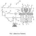
- FIG. 1 a device for the plasma taphole welding according to the prior art is shown and designated 100 in total.
- the device has a welding torch 1, which is aligned with a workpiece 8.
- the welding torch 1 has an electrode 2, preferably a non-burning or non-consumable tungsten electrode 2, which is connected to the negative terminal of a welding power source 12 via line 13.
- the electrode 2 is surrounded by a first nozzle 3, in whose lumen 5 a plasma gas with a volume flow and a composition is provided.
- Burner 1 has a further nozzle 4, which concentrically surrounds the first nozzle and the electrode, and in whose lumen 6 a further process gas, for example a focusing gas and / or an inert gas with a further volume flow and a further composition is provided can be.
- a further process gas for example a focusing gas and / or an inert gas with a further volume flow and a further composition is provided can be.
- Other nozzles, in which further process gases can be provided, can be provided, but are not shown for the sake of simplicity.
- a plasma jet 7 is formed under the influence of the voltage on the electrode 2 in the presence of the plasma gas 5.
- the figure shows how the plasma jet 7 penetrates the workpiece 8 through an engraving hole 9 from an inlet side 8 'in the direction of an exit side 8 " Part of a Formiergasschiene can be formed.
- the electrical conductor 10 is connected via lines 14 and 16, the workpiece 8 via lines 14 and 15 to the positive pole of the welding power source 12.
- a measurement or evaluation unit 19 symbolized here as a computer, shown, the or via the measuring lines 17 and 18, the currents I 1 and I 2 between the electrode 2 and the workpiece 8 , ent.dem conductor 10 measures.
- the current flow I 2 is referred to as penetration current which is variable depending on variable process variables.
- the penetration current can be used with particular preference as an indicator for variable boundary conditions of the welding process.
- the time (T) is plotted on the abscissa and the magnitude of a gas volume flow (V) is plotted on the ordinate, for example in liters per second.
- V gas volume flow
- temporal courses of gas compositions 22 of welding gases according to particularly preferred embodiments of the invention are shown.
- the gas compositions 22 each have three gas components A, B and C, which together give a mixed gas. It is understood that in addition to three gas components and any other number can be provided without departing from the scope of the invention, and that gas mixtures can be used in turn for gas components in addition to pure gases.
- At least one of the components A, B and C may also be composed of a plurality of gas streams, wherein by adding or removing a corresponding gas flow, the total volume flow of the component is changeable.
- the curves given here are not to be considered as true to scale.
- a change of boundary conditions E1 and E2 is made, which is appropriately announced to the system. It should be understood, however, that in addition to a corresponding boundary condition change E1 or E2 at the times T1 and T2, the provision of corresponding other signals can be carried out, leading in a comparable manner to a change in the gas composition.
- a boundary condition E1 can act on a first gas, for example the plasma gas, whereupon a corresponding change of a second gas, which is derived from the first change, is then initiated.
- a first gas for example the plasma gas
- a second gas which is derived from the first change
- FIG. 2A shows the time course of a non-pulsed (continuously) provided gas composition 22.
- the gas composition has a first gas composition from time T0 (for example, from the beginning of the welding process), wherein gas component A has the highest concentration, the highest volume flow or the highest partial pressure (im hereinafter referred to as contribution). If a first boundary condition change E1 is detected at a first time T1, or if the system receives another corresponding signal, which for example indicates a narrowing of the welding gap or a decrease in the penetration current, the contribution of this gas A can be reduced. The contribution of gas B, however, is increased.
- the system can be effected by a corresponding reduction of a heavier ionizable gas over a more easily ionizable gas in the plasma gas, a higher energy density of the plasma jet, whereas a change in the opposite direction causes a corresponding reduction.
- the third component C for example a doping gas, remains at the same level. If a further change E2 occurs at a second time T2, the system returns to the initial state, with the contribution of component A being raised again and that of component B being reduced.
- FIG. 2B It is shown how the contributions of two gas components A and B each change with a sinusoidal course. The phases of the curves are offset by 180 °, causing a pulsating composition change. Analogous to the previous figure, a boundary condition change E1 is detected at time T1. Because of this, a third gas component C, which was not previously part of the gas mixture, is now switched on. As above, the system returns to the initial state at time T2. As part of the FIG. 2B increases between time T1 and T2, the total volume flow to the contribution of the gas C. In this way, for example, an increased back pressure can be effected.
- a gas component A is continuously pulsed with a sinusoidal shape.
- a gas component C remains constant.
- the contribution of a gas B is increased, at the same time a base pressure of the component A is lowered (for example by switching off a continuous gas source).
- the difference between the maximum and minimum flow rate of the gas A does not change.
- the total pressure of the composition 22 (except for the continuous pulses) is not changed.
- each non-superimposed frequencies are shown, a superposition of the corresponding curves, in particular with high-frequency pulses, can be done in any way, without departing from the invention. Likewise, it may be provided to superimpose the waveforms with any other functions.
- the shapes for the respective courses of plasma, focusing and inert gas flow are in the subfigures of FIG. 2 only schematically indicated and to be considered as an example. They can accommodate the task-specific requirements of concrete welding tasks, such as rising speeds, waste rates, intermediate impulses and shoulders (eg at transitions).
- volume flows 20 relate in particular selectively to the change with time of the volume flows of plasma, focusing and protective gas. Also in all sub-figures at certain times T1 and T2 there is a change of boundary conditions E1 and E2, respectively, which is appropriately announced to the system.
- a boundary condition E1 can act on a first process gas, for example the plasma gas, whereupon at time T2 a corresponding (identical or different) change with respect to a second process gas is initiated, which is based on the first boundary condition and of the first Change is derived.
- commands of a corresponding temporally running welding program can be processed.
- FIG. 3A shows the time course of a non-pulsed (continuously) provided gas volume flow 20.
- the volume flow 20 runs between time T0 and T1 initially at a high level. If a first boundary condition change E1 is detected at a first time T1, or if the system receives another corresponding signal which, for example, characterizes a narrowing of the welding gap or a decrease in the penetration current, the gas volume flow, for example the gas volume flow of the plasma gas, can be caused to lower level is lowered. If a further change E2 occurs at a second point in time T2, it is now possible, for example, to cause the corresponding gas volume flow to return slowly and continuously to its original level. As a result of this change in the form of a continuous increase, a continuously increasing material thickness can be accommodated.
- FIG. 3B It is shown how a profile following a rectangular profile of a gas volume flow 20 at time T1 (corresponding to a boundary condition change E1) is changed in terms of its frequency. After determining a further change in the boundary conditions E2 at time T2, the system returns to original course of the gas flow 20 back. In this way, for example, a different frequency of the vibrations in the weld pool can be effected, whereby viscosity changes can be compensated.
- FIG. 3C shows in an analogous manner, as at a first time T1 (corresponding to E1), a rectangular signal of a gas volume flow 20 is changed in amplitude, for example, to cause a stronger vibration. At a second time T2 (corresponding to E2), the amplitude is then lowered to the original level, a baseline offset also being shown in the figure. This can for example be effected by switching off a continuously operating gas source, whereby the total pressure on the melt can be reduced.
- FIG. 4 shows two sinusoidal signals of gas flow rates 20, 21 of corresponding different process gases, such as the plasma gas on the one hand and the focusing gas on the other.
- signals 20 and 21 are phase shifted by about 120 °.
- the amplitude and at the same time the frequency of both gas flow rates 20 and 21 is increased.
- there is a shift of the phases which are now offset by 180 ° to each other.
- a constraint change E2 is again detected. Frequency, amplitude and phases of the signals 20 and 21 are changed again. From the time T2, the signals of the gas flow rates 20 and 21 in the exemplary representation of the FIG. 4 after a transient phase in phase and with the same frequency and amplitude.
Landscapes
- Engineering & Computer Science (AREA)
- Physics & Mathematics (AREA)
- Plasma & Fusion (AREA)
- Mechanical Engineering (AREA)
- Arc Welding In General (AREA)
Priority Applications (1)
| Application Number | Priority Date | Filing Date | Title |
|---|---|---|---|
| US12/837,534 US20110011836A1 (en) | 2009-07-16 | 2010-07-16 | Method and device for plasma keyhole welding |
Applications Claiming Priority (2)
| Application Number | Priority Date | Filing Date | Title |
|---|---|---|---|
| DE200910027784 DE102009027784A1 (de) | 2009-07-16 | 2009-07-16 | Verfahren und Vorrichtung zum Plasma-Stichlochschweißen |
| DE102009027785A DE102009027785A1 (de) | 2009-07-16 | 2009-07-16 | Verfahren und Vorrichtung zum Plasma-Stichlochschweißen |
Publications (2)
| Publication Number | Publication Date |
|---|---|
| EP2277655A1 true EP2277655A1 (fr) | 2011-01-26 |
| EP2277655B1 EP2277655B1 (fr) | 2013-05-15 |
Family
ID=41560389
Family Applications (1)
| Application Number | Title | Priority Date | Filing Date |
|---|---|---|---|
| EP09013534.4A Not-in-force EP2277655B1 (fr) | 2009-07-16 | 2009-10-27 | Procédé et dispositif destiné au soudage 'keyhole' par plasma avec modification de l'écoulment volumique et/ou de la composition du gaz en fonction de conditions limites du procédé de soudage |
Country Status (2)
| Country | Link |
|---|---|
| US (1) | US20110011836A1 (fr) |
| EP (1) | EP2277655B1 (fr) |
Cited By (2)
| Publication number | Priority date | Publication date | Assignee | Title |
|---|---|---|---|---|
| EP2829349A1 (fr) | 2013-07-26 | 2015-01-28 | Linde Aktiengesellschaft | Brûleur de soudage et appareil de soudage avec électrode creuse et matériau d'apport de soudage ajouté sans potentiel, procédé de soudage et utilisation d'un gaz de processus |
| DE102014013047A1 (de) | 2014-09-02 | 2016-03-03 | Linde Aktiengesellschaft | Schweißbrenner und Schweißverfahren mit ringförmiger Elektrodenanordnung |
Families Citing this family (1)
| Publication number | Priority date | Publication date | Assignee | Title |
|---|---|---|---|---|
| JP5981735B2 (ja) * | 2011-09-29 | 2016-08-31 | 株式会社ダイヘン | プラズマキーホール溶接システム、および、プラズマキーホール溶接方法 |
Citations (11)
| Publication number | Priority date | Publication date | Assignee | Title |
|---|---|---|---|---|
| US3484575A (en) | 1967-04-24 | 1969-12-16 | Air Reduction | Pulsed welding and cutting by variation of composition of shielding gas |
| JPS61293668A (ja) * | 1985-06-20 | 1986-12-24 | Ishikawajima Harima Heavy Ind Co Ltd | プラズマ溶接のクレ−タ処理方法 |
| EP0257766A2 (fr) | 1986-08-21 | 1988-03-02 | The Electricity Council | Méthode et appareil pour couper ou souder |
| US4739146A (en) * | 1986-02-25 | 1988-04-19 | Metallurgical Industries, Inc. | Method for applying a weld bead to a thin section of a substrate |
| US5304776A (en) * | 1993-03-24 | 1994-04-19 | Steven R. Buerkel | System for welding pipes |
| EP0689896A1 (fr) | 1994-06-28 | 1996-01-03 | KABUSHIKI KAISHA KOBE SEIKO SHO also known as KOBE STEEL LTD. | Procédé de soudage au plasma |
| JPH0839259A (ja) | 1994-07-29 | 1996-02-13 | Kobe Steel Ltd | ガスパルスプラズマ溶接方法 |
| US5801355A (en) * | 1994-05-25 | 1998-09-01 | Komatsu Ltd. | Plasma piercing with non-oxidative plasma gas and plasma cutting with oxidative plasma gas |
| US6255618B1 (en) * | 1997-02-05 | 2001-07-03 | Komatsu Ltd. | Method and apparatus for spot welding a work having a plurality of welding materials placed on top of each other by boring a hole to release vapors |
| DE102007017223A1 (de) | 2007-04-12 | 2008-10-16 | Linde Ag | Verfahren zum Plasma-Stichlochschweißen |
| DE102007017224A1 (de) | 2007-04-12 | 2008-10-16 | Linde Ag | Verfahren zum Plasma-Stichlochschweißen |
Family Cites Families (2)
| Publication number | Priority date | Publication date | Assignee | Title |
|---|---|---|---|---|
| US20060011592A1 (en) * | 2004-07-14 | 2006-01-19 | Pei-Chung Wang | Laser welding control |
| DE102008044203A1 (de) * | 2008-11-28 | 2010-06-02 | Linde Aktiengesellschaft | Verfahren und Vorrichtung zum Plasma-Stichlochschweißen |
-
2009
- 2009-10-27 EP EP09013534.4A patent/EP2277655B1/fr not_active Not-in-force
-
2010
- 2010-07-16 US US12/837,534 patent/US20110011836A1/en not_active Abandoned
Patent Citations (11)
| Publication number | Priority date | Publication date | Assignee | Title |
|---|---|---|---|---|
| US3484575A (en) | 1967-04-24 | 1969-12-16 | Air Reduction | Pulsed welding and cutting by variation of composition of shielding gas |
| JPS61293668A (ja) * | 1985-06-20 | 1986-12-24 | Ishikawajima Harima Heavy Ind Co Ltd | プラズマ溶接のクレ−タ処理方法 |
| US4739146A (en) * | 1986-02-25 | 1988-04-19 | Metallurgical Industries, Inc. | Method for applying a weld bead to a thin section of a substrate |
| EP0257766A2 (fr) | 1986-08-21 | 1988-03-02 | The Electricity Council | Méthode et appareil pour couper ou souder |
| US5304776A (en) * | 1993-03-24 | 1994-04-19 | Steven R. Buerkel | System for welding pipes |
| US5801355A (en) * | 1994-05-25 | 1998-09-01 | Komatsu Ltd. | Plasma piercing with non-oxidative plasma gas and plasma cutting with oxidative plasma gas |
| EP0689896A1 (fr) | 1994-06-28 | 1996-01-03 | KABUSHIKI KAISHA KOBE SEIKO SHO also known as KOBE STEEL LTD. | Procédé de soudage au plasma |
| JPH0839259A (ja) | 1994-07-29 | 1996-02-13 | Kobe Steel Ltd | ガスパルスプラズマ溶接方法 |
| US6255618B1 (en) * | 1997-02-05 | 2001-07-03 | Komatsu Ltd. | Method and apparatus for spot welding a work having a plurality of welding materials placed on top of each other by boring a hole to release vapors |
| DE102007017223A1 (de) | 2007-04-12 | 2008-10-16 | Linde Ag | Verfahren zum Plasma-Stichlochschweißen |
| DE102007017224A1 (de) | 2007-04-12 | 2008-10-16 | Linde Ag | Verfahren zum Plasma-Stichlochschweißen |
Cited By (2)
| Publication number | Priority date | Publication date | Assignee | Title |
|---|---|---|---|---|
| EP2829349A1 (fr) | 2013-07-26 | 2015-01-28 | Linde Aktiengesellschaft | Brûleur de soudage et appareil de soudage avec électrode creuse et matériau d'apport de soudage ajouté sans potentiel, procédé de soudage et utilisation d'un gaz de processus |
| DE102014013047A1 (de) | 2014-09-02 | 2016-03-03 | Linde Aktiengesellschaft | Schweißbrenner und Schweißverfahren mit ringförmiger Elektrodenanordnung |
Also Published As
| Publication number | Publication date |
|---|---|
| EP2277655B1 (fr) | 2013-05-15 |
| US20110011836A1 (en) | 2011-01-20 |
Similar Documents
| Publication | Publication Date | Title |
|---|---|---|
| EP2191925B1 (fr) | Procédé de, dispositif et programme d'ordinateur pour le soudage plasma par trou d'aiguille avec changement actif du courant de pénétration durant le soudage | |
| DE3103247C2 (de) | Mittelfrequenz-Impuls-Lichtbogenschweißverfahren für das Wolfram-Schutzgas-(WIG) Verbindungsschweißen | |
| AT501489B1 (de) | Verfahren zum steuern und/oder regeln eines schweissgerätes und schweissgerät | |
| EP1901874B1 (fr) | Procede de soudage par transfert de metal a froid et dispositif de soudage | |
| EP1707296B2 (fr) | Procédé de soudage à l'arc | |
| EP2359974B1 (fr) | Procédé de soudage à l'arc et source d'électricité de soudage pour la réalisation du procédé | |
| EP1644156B1 (fr) | Procede permettant d'alimenter une torche a plasma avec un gaz, un gaz mixte ou un melange gazeux par regulation combinee du debit volumetrique et de la pression, et dispositif servant a la mise en oeuvre de ce procede | |
| EP1977847B1 (fr) | Procédé destiné au soudage par électrode en tandem | |
| DE202013012051U1 (de) | System zum Starten und Verwenden einer kombinierten Fülldrahtzufuhr und hoch-intensiven Energiequelle zum Schweissen | |
| EP2829349B1 (fr) | Brûleur de soudage et appareil de soudage avec électrode creuse et matériau d'apport de soudage ajouté sans potentiel, procédé de soudage et utilisation d'un gaz de processus | |
| WO2008125275A1 (fr) | Procédé de soudage en bouchon au plasma | |
| EP2277655B1 (fr) | Procédé et dispositif destiné au soudage 'keyhole' par plasma avec modification de l'écoulment volumique et/ou de la composition du gaz en fonction de conditions limites du procédé de soudage | |
| WO2008125276A1 (fr) | Procédé de soudage en bouchon au plasma | |
| DE4417397C3 (de) | Befestigungselement und Vorrichtung für eine Schweißvorrichtung zum Befestigen eines solchen Elementes auf vorgelochtem Blechmaterial | |
| EP2777858B1 (fr) | Chauffage d'un matériau d'apport pour le soudage à l'arc | |
| DE102009027785A1 (de) | Verfahren und Vorrichtung zum Plasma-Stichlochschweißen | |
| EP1980354B1 (fr) | Procédé pour soudage en bouchon au moyen de plasma | |
| EP1379354B1 (fr) | Procede de soudage a l'arc de metal sous gaz protecteur | |
| DE102009027784A1 (de) | Verfahren und Vorrichtung zum Plasma-Stichlochschweißen | |
| EP4023380A1 (fr) | Procédé de soudage destiné au fonctionnement d'un robot de soudage à suivi du cordon de soudure | |
| DE10128793B4 (de) | Verfahren zur Bearbeitung eines Werkstücks mit einem Laserstrahl | |
| DE212015000071U1 (de) | System zur Verwendung einer kombinierten Fülldrahtzufuhr- und Hochintensitäts-Energiequelle zum Schweissen mit gesteuerter Lichtbogenbildungsfrequenz | |
| EP4010142B1 (fr) | Procédé et dispositif de stabilisation d'une transition entre différentes phases d'un procedé de soudage | |
| DE102007032574A1 (de) | Verfahren zum Lichtbogenfügen mit Flachdraht | |
| EP1640100B1 (fr) | Méthode et dispositif de soudage à l'arc sous gaz de protection |
Legal Events
| Date | Code | Title | Description |
|---|---|---|---|
| PUAI | Public reference made under article 153(3) epc to a published international application that has entered the european phase |
Free format text: ORIGINAL CODE: 0009012 |
|
| AK | Designated contracting states |
Kind code of ref document: A1 Designated state(s): AT BE BG CH CY CZ DE DK EE ES FI FR GB GR HR HU IE IS IT LI LT LU LV MC MK MT NL NO PL PT RO SE SI SK SM TR |
|
| AX | Request for extension of the european patent |
Extension state: AL BA RS |
|
| 17P | Request for examination filed |
Effective date: 20110316 |
|
| 17Q | First examination report despatched |
Effective date: 20110405 |
|
| GRAP | Despatch of communication of intention to grant a patent |
Free format text: ORIGINAL CODE: EPIDOSNIGR1 |
|
| RIC1 | Information provided on ipc code assigned before grant |
Ipc: B23K 10/00 20060101ALI20121221BHEP Ipc: B23K 9/167 20060101AFI20121221BHEP Ipc: B23K 10/02 20060101ALI20121221BHEP |
|
| GRAS | Grant fee paid |
Free format text: ORIGINAL CODE: EPIDOSNIGR3 |
|
| GRAA | (expected) grant |
Free format text: ORIGINAL CODE: 0009210 |
|
| AK | Designated contracting states |
Kind code of ref document: B1 Designated state(s): AT BE BG CH CY CZ DE DK EE ES FI FR GB GR HR HU IE IS IT LI LT LU LV MC MK MT NL NO PL PT RO SE SI SK SM TR |
|
| REG | Reference to a national code |
Ref country code: GB Ref legal event code: FG4D Free format text: NOT ENGLISH Ref country code: CH Ref legal event code: EP |
|
| REG | Reference to a national code |
Ref country code: AT Ref legal event code: REF Ref document number: 611875 Country of ref document: AT Kind code of ref document: T Effective date: 20130615 |
|
| REG | Reference to a national code |
Ref country code: IE Ref legal event code: FG4D Free format text: LANGUAGE OF EP DOCUMENT: GERMAN |
|
| REG | Reference to a national code |
Ref country code: DE Ref legal event code: R096 Ref document number: 502009007079 Country of ref document: DE Effective date: 20130711 |
|
| REG | Reference to a national code |
Ref country code: LT Ref legal event code: MG4D |
|
| REG | Reference to a national code |
Ref country code: NL Ref legal event code: VDEP Effective date: 20130515 |
|
| PG25 | Lapsed in a contracting state [announced via postgrant information from national office to epo] |
Ref country code: ES Free format text: LAPSE BECAUSE OF FAILURE TO SUBMIT A TRANSLATION OF THE DESCRIPTION OR TO PAY THE FEE WITHIN THE PRESCRIBED TIME-LIMIT Effective date: 20130826 Ref country code: IS Free format text: LAPSE BECAUSE OF FAILURE TO SUBMIT A TRANSLATION OF THE DESCRIPTION OR TO PAY THE FEE WITHIN THE PRESCRIBED TIME-LIMIT Effective date: 20130915 Ref country code: LT Free format text: LAPSE BECAUSE OF FAILURE TO SUBMIT A TRANSLATION OF THE DESCRIPTION OR TO PAY THE FEE WITHIN THE PRESCRIBED TIME-LIMIT Effective date: 20130515 Ref country code: SE Free format text: LAPSE BECAUSE OF FAILURE TO SUBMIT A TRANSLATION OF THE DESCRIPTION OR TO PAY THE FEE WITHIN THE PRESCRIBED TIME-LIMIT Effective date: 20130515 Ref country code: SI Free format text: LAPSE BECAUSE OF FAILURE TO SUBMIT A TRANSLATION OF THE DESCRIPTION OR TO PAY THE FEE WITHIN THE PRESCRIBED TIME-LIMIT Effective date: 20130515 Ref country code: GR Free format text: LAPSE BECAUSE OF FAILURE TO SUBMIT A TRANSLATION OF THE DESCRIPTION OR TO PAY THE FEE WITHIN THE PRESCRIBED TIME-LIMIT Effective date: 20130816 Ref country code: FI Free format text: LAPSE BECAUSE OF FAILURE TO SUBMIT A TRANSLATION OF THE DESCRIPTION OR TO PAY THE FEE WITHIN THE PRESCRIBED TIME-LIMIT Effective date: 20130515 Ref country code: PT Free format text: LAPSE BECAUSE OF FAILURE TO SUBMIT A TRANSLATION OF THE DESCRIPTION OR TO PAY THE FEE WITHIN THE PRESCRIBED TIME-LIMIT Effective date: 20130916 Ref country code: NO Free format text: LAPSE BECAUSE OF FAILURE TO SUBMIT A TRANSLATION OF THE DESCRIPTION OR TO PAY THE FEE WITHIN THE PRESCRIBED TIME-LIMIT Effective date: 20130815 |
|
| PG25 | Lapsed in a contracting state [announced via postgrant information from national office to epo] |
Ref country code: HR Free format text: LAPSE BECAUSE OF FAILURE TO SUBMIT A TRANSLATION OF THE DESCRIPTION OR TO PAY THE FEE WITHIN THE PRESCRIBED TIME-LIMIT Effective date: 20130515 Ref country code: BG Free format text: LAPSE BECAUSE OF FAILURE TO SUBMIT A TRANSLATION OF THE DESCRIPTION OR TO PAY THE FEE WITHIN THE PRESCRIBED TIME-LIMIT Effective date: 20130815 Ref country code: PL Free format text: LAPSE BECAUSE OF FAILURE TO SUBMIT A TRANSLATION OF THE DESCRIPTION OR TO PAY THE FEE WITHIN THE PRESCRIBED TIME-LIMIT Effective date: 20130515 |
|
| PG25 | Lapsed in a contracting state [announced via postgrant information from national office to epo] |
Ref country code: LV Free format text: LAPSE BECAUSE OF FAILURE TO SUBMIT A TRANSLATION OF THE DESCRIPTION OR TO PAY THE FEE WITHIN THE PRESCRIBED TIME-LIMIT Effective date: 20130515 |
|
| PG25 | Lapsed in a contracting state [announced via postgrant information from national office to epo] |
Ref country code: DK Free format text: LAPSE BECAUSE OF FAILURE TO SUBMIT A TRANSLATION OF THE DESCRIPTION OR TO PAY THE FEE WITHIN THE PRESCRIBED TIME-LIMIT Effective date: 20130515 Ref country code: SK Free format text: LAPSE BECAUSE OF FAILURE TO SUBMIT A TRANSLATION OF THE DESCRIPTION OR TO PAY THE FEE WITHIN THE PRESCRIBED TIME-LIMIT Effective date: 20130515 Ref country code: EE Free format text: LAPSE BECAUSE OF FAILURE TO SUBMIT A TRANSLATION OF THE DESCRIPTION OR TO PAY THE FEE WITHIN THE PRESCRIBED TIME-LIMIT Effective date: 20130515 Ref country code: CZ Free format text: LAPSE BECAUSE OF FAILURE TO SUBMIT A TRANSLATION OF THE DESCRIPTION OR TO PAY THE FEE WITHIN THE PRESCRIBED TIME-LIMIT Effective date: 20130515 |
|
| PG25 | Lapsed in a contracting state [announced via postgrant information from national office to epo] |
Ref country code: IT Free format text: LAPSE BECAUSE OF FAILURE TO SUBMIT A TRANSLATION OF THE DESCRIPTION OR TO PAY THE FEE WITHIN THE PRESCRIBED TIME-LIMIT Effective date: 20130515 Ref country code: RO Free format text: LAPSE BECAUSE OF FAILURE TO SUBMIT A TRANSLATION OF THE DESCRIPTION OR TO PAY THE FEE WITHIN THE PRESCRIBED TIME-LIMIT Effective date: 20130515 Ref country code: NL Free format text: LAPSE BECAUSE OF FAILURE TO SUBMIT A TRANSLATION OF THE DESCRIPTION OR TO PAY THE FEE WITHIN THE PRESCRIBED TIME-LIMIT Effective date: 20130515 |
|
| PLBE | No opposition filed within time limit |
Free format text: ORIGINAL CODE: 0009261 |
|
| STAA | Information on the status of an ep patent application or granted ep patent |
Free format text: STATUS: NO OPPOSITION FILED WITHIN TIME LIMIT |
|
| 26N | No opposition filed |
Effective date: 20140218 |
|
| BERE | Be: lapsed |
Owner name: LINDE A.G. Effective date: 20131031 |
|
| REG | Reference to a national code |
Ref country code: DE Ref legal event code: R097 Ref document number: 502009007079 Country of ref document: DE Effective date: 20140218 |
|
| PG25 | Lapsed in a contracting state [announced via postgrant information from national office to epo] |
Ref country code: MC Free format text: LAPSE BECAUSE OF FAILURE TO SUBMIT A TRANSLATION OF THE DESCRIPTION OR TO PAY THE FEE WITHIN THE PRESCRIBED TIME-LIMIT Effective date: 20130515 |
|
| REG | Reference to a national code |
Ref country code: CH Ref legal event code: PL |
|
| GBPC | Gb: european patent ceased through non-payment of renewal fee |
Effective date: 20131027 |
|
| REG | Reference to a national code |
Ref country code: DE Ref legal event code: R119 Ref document number: 502009007079 Country of ref document: DE Effective date: 20140501 |
|
| REG | Reference to a national code |
Ref country code: IE Ref legal event code: MM4A |
|
| PG25 | Lapsed in a contracting state [announced via postgrant information from national office to epo] |
Ref country code: GB Free format text: LAPSE BECAUSE OF NON-PAYMENT OF DUE FEES Effective date: 20131027 Ref country code: CH Free format text: LAPSE BECAUSE OF NON-PAYMENT OF DUE FEES Effective date: 20131031 Ref country code: LI Free format text: LAPSE BECAUSE OF NON-PAYMENT OF DUE FEES Effective date: 20131031 |
|
| REG | Reference to a national code |
Ref country code: FR Ref legal event code: ST Effective date: 20140630 |
|
| PG25 | Lapsed in a contracting state [announced via postgrant information from national office to epo] |
Ref country code: DE Free format text: LAPSE BECAUSE OF NON-PAYMENT OF DUE FEES Effective date: 20140501 Ref country code: FR Free format text: LAPSE BECAUSE OF NON-PAYMENT OF DUE FEES Effective date: 20131031 |
|
| PG25 | Lapsed in a contracting state [announced via postgrant information from national office to epo] |
Ref country code: BE Free format text: LAPSE BECAUSE OF NON-PAYMENT OF DUE FEES Effective date: 20131031 |
|
| PG25 | Lapsed in a contracting state [announced via postgrant information from national office to epo] |
Ref country code: IE Free format text: LAPSE BECAUSE OF NON-PAYMENT OF DUE FEES Effective date: 20131027 |
|
| PG25 | Lapsed in a contracting state [announced via postgrant information from national office to epo] |
Ref country code: SM Free format text: LAPSE BECAUSE OF FAILURE TO SUBMIT A TRANSLATION OF THE DESCRIPTION OR TO PAY THE FEE WITHIN THE PRESCRIBED TIME-LIMIT Effective date: 20130515 |
|
| PG25 | Lapsed in a contracting state [announced via postgrant information from national office to epo] |
Ref country code: TR Free format text: LAPSE BECAUSE OF FAILURE TO SUBMIT A TRANSLATION OF THE DESCRIPTION OR TO PAY THE FEE WITHIN THE PRESCRIBED TIME-LIMIT Effective date: 20130515 Ref country code: CY Free format text: LAPSE BECAUSE OF FAILURE TO SUBMIT A TRANSLATION OF THE DESCRIPTION OR TO PAY THE FEE WITHIN THE PRESCRIBED TIME-LIMIT Effective date: 20130515 |
|
| PG25 | Lapsed in a contracting state [announced via postgrant information from national office to epo] |
Ref country code: MK Free format text: LAPSE BECAUSE OF FAILURE TO SUBMIT A TRANSLATION OF THE DESCRIPTION OR TO PAY THE FEE WITHIN THE PRESCRIBED TIME-LIMIT Effective date: 20130515 Ref country code: HU Free format text: LAPSE BECAUSE OF FAILURE TO SUBMIT A TRANSLATION OF THE DESCRIPTION OR TO PAY THE FEE WITHIN THE PRESCRIBED TIME-LIMIT; INVALID AB INITIO Effective date: 20091027 Ref country code: LU Free format text: LAPSE BECAUSE OF NON-PAYMENT OF DUE FEES Effective date: 20131027 |
|
| PG25 | Lapsed in a contracting state [announced via postgrant information from national office to epo] |
Ref country code: MT Free format text: LAPSE BECAUSE OF FAILURE TO SUBMIT A TRANSLATION OF THE DESCRIPTION OR TO PAY THE FEE WITHIN THE PRESCRIBED TIME-LIMIT Effective date: 20130515 |
|
| REG | Reference to a national code |
Ref country code: AT Ref legal event code: MM01 Ref document number: 611875 Country of ref document: AT Kind code of ref document: T Effective date: 20141027 |
|
| PG25 | Lapsed in a contracting state [announced via postgrant information from national office to epo] |
Ref country code: AT Free format text: LAPSE BECAUSE OF NON-PAYMENT OF DUE FEES Effective date: 20141027 |