EP2277366B1 - Walking-type working machine - Google Patents
Walking-type working machine Download PDFInfo
- Publication number
- EP2277366B1 EP2277366B1 EP09742652A EP09742652A EP2277366B1 EP 2277366 B1 EP2277366 B1 EP 2277366B1 EP 09742652 A EP09742652 A EP 09742652A EP 09742652 A EP09742652 A EP 09742652A EP 2277366 B1 EP2277366 B1 EP 2277366B1
- Authority
- EP
- European Patent Office
- Prior art keywords
- working machine
- grip
- handle
- walk
- cartridge
- Prior art date
- Legal status (The legal status is an assumption and is not a legal conclusion. Google has not performed a legal analysis and makes no representation as to the accuracy of the status listed.)
- Not-in-force
Links
Images


Classifications
-
- B—PERFORMING OPERATIONS; TRANSPORTING
- B60—VEHICLES IN GENERAL
- B60K—ARRANGEMENT OR MOUNTING OF PROPULSION UNITS OR OF TRANSMISSIONS IN VEHICLES; ARRANGEMENT OR MOUNTING OF PLURAL DIVERSE PRIME-MOVERS IN VEHICLES; AUXILIARY DRIVES FOR VEHICLES; INSTRUMENTATION OR DASHBOARDS FOR VEHICLES; ARRANGEMENTS IN CONNECTION WITH COOLING, AIR INTAKE, GAS EXHAUST OR FUEL SUPPLY OF PROPULSION UNITS IN VEHICLES
- B60K15/00—Arrangement in connection with fuel supply of combustion engines or other fuel consuming energy converters, e.g. fuel cells; Mounting or construction of fuel tanks
- B60K15/03—Fuel tanks
- B60K15/063—Arrangement of tanks
- B60K15/067—Mounting of tanks
- B60K15/07—Mounting of tanks of gas tanks
-
- A—HUMAN NECESSITIES
- A01—AGRICULTURE; FORESTRY; ANIMAL HUSBANDRY; HUNTING; TRAPPING; FISHING
- A01B—SOIL WORKING IN AGRICULTURE OR FORESTRY; PARTS, DETAILS, OR ACCESSORIES OF AGRICULTURAL MACHINES OR IMPLEMENTS, IN GENERAL
- A01B33/00—Tilling implements with rotary driven tools, e.g. in combination with fertiliser distributors or seeders, with grubbing chains, with sloping axles, with driven discs
- A01B33/02—Tilling implements with rotary driven tools, e.g. in combination with fertiliser distributors or seeders, with grubbing chains, with sloping axles, with driven discs with tools on horizontal shaft transverse to direction of travel
- A01B33/028—Tilling implements with rotary driven tools, e.g. in combination with fertiliser distributors or seeders, with grubbing chains, with sloping axles, with driven discs with tools on horizontal shaft transverse to direction of travel of the walk-behind type
-
- A—HUMAN NECESSITIES
- A01—AGRICULTURE; FORESTRY; ANIMAL HUSBANDRY; HUNTING; TRAPPING; FISHING
- A01B—SOIL WORKING IN AGRICULTURE OR FORESTRY; PARTS, DETAILS, OR ACCESSORIES OF AGRICULTURAL MACHINES OR IMPLEMENTS, IN GENERAL
- A01B33/00—Tilling implements with rotary driven tools, e.g. in combination with fertiliser distributors or seeders, with grubbing chains, with sloping axles, with driven discs
- A01B33/16—Tilling implements with rotary driven tools, e.g. in combination with fertiliser distributors or seeders, with grubbing chains, with sloping axles, with driven discs with special additional arrangements
-
- F—MECHANICAL ENGINEERING; LIGHTING; HEATING; WEAPONS; BLASTING
- F17—STORING OR DISTRIBUTING GASES OR LIQUIDS
- F17C—VESSELS FOR CONTAINING OR STORING COMPRESSED, LIQUEFIED OR SOLIDIFIED GASES; FIXED-CAPACITY GAS-HOLDERS; FILLING VESSELS WITH, OR DISCHARGING FROM VESSELS, COMPRESSED, LIQUEFIED, OR SOLIDIFIED GASES
- F17C13/00—Details of vessels or of the filling or discharging of vessels
- F17C13/08—Mounting arrangements for vessels
- F17C13/084—Mounting arrangements for vessels for small-sized storage vessels, e.g. compressed gas cylinders or bottles, disposable gas vessels, vessels adapted for automotive use
- F17C13/085—Mounting arrangements for vessels for small-sized storage vessels, e.g. compressed gas cylinders or bottles, disposable gas vessels, vessels adapted for automotive use on wheels
-
- B—PERFORMING OPERATIONS; TRANSPORTING
- B60—VEHICLES IN GENERAL
- B60Y—INDEXING SCHEME RELATING TO ASPECTS CROSS-CUTTING VEHICLE TECHNOLOGY
- B60Y2200/00—Type of vehicle
- B60Y2200/40—Special vehicles
- B60Y2200/41—Construction vehicles, e.g. graders, excavators
-
- F—MECHANICAL ENGINEERING; LIGHTING; HEATING; WEAPONS; BLASTING
- F17—STORING OR DISTRIBUTING GASES OR LIQUIDS
- F17C—VESSELS FOR CONTAINING OR STORING COMPRESSED, LIQUEFIED OR SOLIDIFIED GASES; FIXED-CAPACITY GAS-HOLDERS; FILLING VESSELS WITH, OR DISCHARGING FROM VESSELS, COMPRESSED, LIQUEFIED, OR SOLIDIFIED GASES
- F17C2205/00—Vessel construction, in particular mounting arrangements, attachments or identifications means
- F17C2205/01—Mounting arrangements
- F17C2205/0103—Exterior arrangements
- F17C2205/0111—Boxes
-
- F—MECHANICAL ENGINEERING; LIGHTING; HEATING; WEAPONS; BLASTING
- F17—STORING OR DISTRIBUTING GASES OR LIQUIDS
- F17C—VESSELS FOR CONTAINING OR STORING COMPRESSED, LIQUEFIED OR SOLIDIFIED GASES; FIXED-CAPACITY GAS-HOLDERS; FILLING VESSELS WITH, OR DISCHARGING FROM VESSELS, COMPRESSED, LIQUEFIED, OR SOLIDIFIED GASES
- F17C2205/00—Vessel construction, in particular mounting arrangements, attachments or identifications means
- F17C2205/01—Mounting arrangements
- F17C2205/0153—Details of mounting arrangements
- F17C2205/0157—Details of mounting arrangements for transport
- F17C2205/0165—Details of mounting arrangements for transport with handgrip
-
- F—MECHANICAL ENGINEERING; LIGHTING; HEATING; WEAPONS; BLASTING
- F17—STORING OR DISTRIBUTING GASES OR LIQUIDS
- F17C—VESSELS FOR CONTAINING OR STORING COMPRESSED, LIQUEFIED OR SOLIDIFIED GASES; FIXED-CAPACITY GAS-HOLDERS; FILLING VESSELS WITH, OR DISCHARGING FROM VESSELS, COMPRESSED, LIQUEFIED, OR SOLIDIFIED GASES
- F17C2221/00—Handled fluid, in particular type of fluid
- F17C2221/03—Mixtures
- F17C2221/032—Hydrocarbons
- F17C2221/035—Propane butane, e.g. LPG, GPL
-
- F—MECHANICAL ENGINEERING; LIGHTING; HEATING; WEAPONS; BLASTING
- F17—STORING OR DISTRIBUTING GASES OR LIQUIDS
- F17C—VESSELS FOR CONTAINING OR STORING COMPRESSED, LIQUEFIED OR SOLIDIFIED GASES; FIXED-CAPACITY GAS-HOLDERS; FILLING VESSELS WITH, OR DISCHARGING FROM VESSELS, COMPRESSED, LIQUEFIED, OR SOLIDIFIED GASES
- F17C2223/00—Handled fluid before transfer, i.e. state of fluid when stored in the vessel or before transfer from the vessel
- F17C2223/01—Handled fluid before transfer, i.e. state of fluid when stored in the vessel or before transfer from the vessel characterised by the phase
- F17C2223/0146—Two-phase
- F17C2223/0153—Liquefied gas, e.g. LPG, GPL
-
- F—MECHANICAL ENGINEERING; LIGHTING; HEATING; WEAPONS; BLASTING
- F17—STORING OR DISTRIBUTING GASES OR LIQUIDS
- F17C—VESSELS FOR CONTAINING OR STORING COMPRESSED, LIQUEFIED OR SOLIDIFIED GASES; FIXED-CAPACITY GAS-HOLDERS; FILLING VESSELS WITH, OR DISCHARGING FROM VESSELS, COMPRESSED, LIQUEFIED, OR SOLIDIFIED GASES
- F17C2223/00—Handled fluid before transfer, i.e. state of fluid when stored in the vessel or before transfer from the vessel
- F17C2223/03—Handled fluid before transfer, i.e. state of fluid when stored in the vessel or before transfer from the vessel characterised by the pressure level
- F17C2223/033—Small pressure, e.g. for liquefied gas
-
- F—MECHANICAL ENGINEERING; LIGHTING; HEATING; WEAPONS; BLASTING
- F17—STORING OR DISTRIBUTING GASES OR LIQUIDS
- F17C—VESSELS FOR CONTAINING OR STORING COMPRESSED, LIQUEFIED OR SOLIDIFIED GASES; FIXED-CAPACITY GAS-HOLDERS; FILLING VESSELS WITH, OR DISCHARGING FROM VESSELS, COMPRESSED, LIQUEFIED, OR SOLIDIFIED GASES
- F17C2270/00—Applications
- F17C2270/07—Applications for household use
- F17C2270/0736—Capsules, e.g. CO2
Definitions
- the present invention relates to a walk-behind working machine having a cartridge-type gas cylinder disposed to extend along a handle post and a gas engine driven by fuel held in the cassette cylinder.
- a walk-behind working machine is known from, for example, Patent Document 1.
- the known walk-behind working machine includes a handle post extending rearwardly upwardly from a rear part of a working machine body and a carrying handle extending upwardly from an upper part of an outer peripheral wall of the handle post.
- the carrying handle is provided with a grip part to be gripped by a hand for allowing lift and carriage of the walk-behind working machine.
- a gas-engine-powered working machine is also known from, for example, Patent Document 2.
- the known working machine includes a working machine body carrying a gas engine thereon, a handle post extending rearwardly upwardly from a rear part of the working machine body, a cylinder housing section provided at an upper part of an outer peripheral wall of the handle post, and a cassette- or cartridge-type gas cylinder housed in the cylinder housing section.
- the carrying handle of Patent Document 1 is arranged to extend upwardly from the upper part of the outer peripheral wall of the handle post.
- the gas cylinder housing section is provided at the upper part of the outer peripheral wall of the handle post.
- the carrying handle and the cylinder housing section are both provided at the upper part of the outer peripheral wall.
- the cylinder housing section presents a bar to mounting of the carrying handle to the handle post of the gas-engine-powered working machine. Consequently, there exists a demand for a working machine which allows mounting of both the cylinder housing section and the carrying handle to the handle post of the gas-engine-powered working machine.
- Document GB 2318861 describes a machine according to the preamble of claim 1.
- a walk-behind working machine which comprises: a working machine body; a handle post extending rearwardly upwardly from a rear part of the working machine body; a cartridge-type gas cylinder disposed to lie along a length of the handle post; a gas engine capable of being driven by fuel contained in the cartridge- type gas cylinder; and a carrying handle disposed on the handle post and having a grip formed to surround the cartridge-type gas cylinder.
- the carrying handle With this arrangement, it becomes possible to carry the walk-behind working machine by gripping and lifting the grip. Further, by arranging the carrying handle to surround the cartridge-type gas cylinder, it becomes possible to dispose both the cylinder housing section and the carrying handle on the handle post. Moreover, with the carrying handle disposed to surround the cartridge-type gas cylinder, the cartridge-type gas cylinder can be protected by the carrying handle.
- the walk-behind working machine further comprises a cylinder cover disposed between the cartridge-type gas cylinder and the carrying handle for holding the cartridge-type gas cylinder and being capable of opening and closing actions.
- a cylinder cover disposed between the cartridge-type gas cylinder and the carrying handle for holding the cartridge-type gas cylinder and being capable of opening and closing actions.
- the cylinder cover is brought into contact with the carrying handle to thereby providing an appropriate degree of opening of the cylinder cover.
- the cartridge-type gas cylinder can be changed easily to thereby easy handling of the machine.
- the grip comprises left and right grip parts extending in a forward direction of the working machine from positions on left and right sides of the cartridge-type gas cylinder in a gradually converging fashion.
- the grip thus has the left and right grip parts.
- the left and right grip parts are provided such that they extend from left and right sides of the gas cylinder in the forward direction of the machine in such a manner as to gradually diverge. This provides a relatively large distance between the left and right grip parts so that the two attendants standing on left and right sides of the machine can hold the respective left and right grip parts without encountering interference one by other.
- the left grip part is inclined leftwardly outwardly and to arrange the right grip part to be inclined righwardly outwardly.
- the back of his right hand can be inclined forwardly in correspondence with the left grip part, whereby the right hand can be placed in a posture suitable for lifting the left grip part.
- the back of his left hand can be inclined forwardly in correspondence with the right grip part, whereby the left hand is placed in a posture suitable for lifting the right grip part.
- the two attendants standing on the left and right sides of the walk-behind working machine can easily grip the respective left and right grip parts, whereby the working machine is imparted with increased mobility.
- the grip has a central grip part extending between front end parts of the left and right grip parts.
- the left and right grip parts By arranging the left and right grip parts to extend in the forward direction of the working machine in a diverging fashion, it is possible to provide a large space or distance between the front end parts of the left and right grip parts. This enables the central grip part to have a large length, whereby gripping (and hence lifting) of the central grip part becomes easy, allowing a single attendant to carry walk-behind working machine. Mobility of the working machine is thus increased.
- a walk-behind tiller will be described as an example of the walk-behind working machine.
- the present invention should not be construed as being limited to the walk-behind tiller.
- the walk-behind working machine 10 as shown in Fig. 1 is comprised of a gas engine 12 placed on an upper end part of a tiller body (working machine body) 11, a fender 13 disposed below the gas engine 12, a plurality of tilling tines disposed below the fender 13 via a tilling shaft 14, a handle post 16 provided at a rear part 11a of the tiller body 11, an operating handle 17 disposed on the handle post 16, a cylinder housing or retaining section 18, a cartridge-type gas cylinder 21 housed in the cylinder housing section 18, and a carrying handle 22 provided on the handle post 16.
- the gas engine 12 is driven by fuel in the gas cylinder or cartridge 21.
- the power produced by the engine 12 is transmitted to the tilling shaft 14 so that the tilling shaft 14 is rotated to till a soil with the tilling tines 15 while the machine runs with the operating handle 17 gripped by an operator.
- the gas engine 12 is of the type which is driven by fuel gas supplied from the gas cylinder or cartridge 12.
- the handle post 16 comprises a tubular member extending rearwardly upwardly from a rear part of the working machine body.
- the operating handle 17 is supported on an upper end part 16a of the handle post 16 via right and left support brackets 23.
- the cylinder housing section 18 is provided on an upper half 25 of the handle post 16 in such a manner as to extend along the cylinder housing section 18.
- the carrying handle 22 for carriage is provided on a generally central peripheral wall section 26.
- the operating handle 17 comprises a tubular member formed into a U-shape as seen from a front side therefor, as shown in Fig. 3 .
- the operating handle 17 has a lower end part 17a mounted to the upper end part 16a of the handle post via the right and left support brackets 23 and is provided at right and left upper or rear end parts 17b with right and left grips 27, 28 (see Fig. 1 ), respectively.
- the cylinder housing section 18 comprises a base 31 provided to extend along the upper half 25 of the handle post 16 and a cylinder cover 32 provided pivotally relative to the base 31.
- the base 31 has a mouthpiece support part, not shown, for removably supporting a mouthpiece of the gas cylinder 21.
- a mouthpiece support part not shown, for removably supporting a mouthpiece of the gas cylinder 21.
- the gas cylinder 21 comprises a commercially available gas cartridge filled with liquefied butane consisting chiefly of butane (hereinafter called "liquefied fuel gas").
- the gas cylinder 21 has a cylinder or container body 34 with a jet nozzle protruding from the mouthpiece of the container body 34, as shown in Fig. 3 . By pressing the jet nozzle into the container body 34, the liquefied fuel gas held inside the container body 34 is lead out into a supply passage 35.
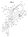
- the cylinder cover 32 is positioned between the gas cartridge or cylinder 21 and the carrying handle 22 and capable of pivotal movement between a closed position P1 ( Fig. 2 ) wherein the gas cylinder 21 is pressed against the base 31 and an opened position P2 (see Fig. 6 ) wherein the gas cylinder mounting and removal are allowed.
- the cylinder cover 32 is held in the closed position P1 in such an orientation as to lie along the upper half 25.
- the cylinder cover 32 comprises a main cover 36 pivotally provided to the base 31, a sub-cover 37 pivotally mounted to a distal end 36a of the main cover 36, and a locking pawl 38 provided on the sub-cover 37.
- the main cover 36 is configured such that it can be held in the closed position P1 by means of a spring member hot shown. By retaining the main cover 36 in the closed position P1, the main cover 36 brought into contact with the gas cylinder 21. As a result, the gas cylinder 21 is press-held by the main cover 36.
- the sub-cover 37 is supported pivotally on a distal end part 36a of the main cover 36 via a support pin 41 and is configured to allow positioning in the closed position P1 via a spring member, not shown. Retaining the sub-cover 37 in the closed position P1 causes the sub-cover 37 to come into contact with the gas cylinder 21. As a result, the gas cylinder is held firmly by the sub-cover 37.
- the locking pawl 38 is brought into locking engagement with the carrying handle 22.
- the main cover 36 and the sub-cover 37 are held in the opened position P2.
- the main cover 36 and the sub-cover 37 are thus opened, it becomes possible to hold the covers 36, 37 in contact with the carrying handle 22 to thereby provide a suitable degree of opening of the covers 36, 37.
- the carrying handle 22 is formed by integrally bending a tubular member.
- the carrying handle 22 includes left and right horizontal bases 43, 44 which are weld-connected to left and right side wall parts 26a, 26b of the generally central peripheral wall 26 of the handle post 16.
- the carrying handle 22 also includes a grip 45 positioned upwardly of the cylinder cover 32.
- the carrying handle 22 is comprised of the left and right horizontal bases 43, 44 provided respectively at the left and right side wall parts 26a, 26b, a left leg part 46 provided on the left horizontal base 43, a right leg part 47 provided on the right horizontal base 44, and the grip 45 provided on the left and right leg parts 46, 47.
- the left horizontal base 43 extends horizontally outwardly from the left side wall part 26a.
- the left horizontal base 43 is positioned below the cylinder housing section 18, with its outer end part 43a located outwardly of a left side part 18a of the cylinder housing section 18.
- the right horizontal base 44 is positioned coaxially with the left horizontal base 43 and extends horizontally outwardly from the right side wall part 26b.
- the right horizontal base 44 is positioned below the cylinder housing section 18, with its outer end part 44a located externally of a right side part 18b of the cylinder housing section 18.
- the left and right horizontal base 43, 44 are formed symmetrically.
- the left leg part 46 extends upwardly from an outer end part 43a of the left horizontal base 43 and is positioned on the left side part 18a of the cylinder housing section 18.
- the right leg part 47 extends upwardly from an outer end part 44a of the right horizontal base 44 and is positioned outwardly of the right side part 18b of the cylinder housing section 18.
- the left and right leg parts 46, 47 are formed symmetrically..
- the grip 45 is provided on the respective upper end parts 46a, 47a of the left and right leg parts 46, 47 and takes the form of a generally U shape.
- the grip 45 comprises left and right grip parts 51, 52 provided on the left and right leg parts 46, 47, and a central grip 53 provided between the left and right grip parts 51, 52.
- the left grip part 51 extends forwardly of the working machine from the upper end part 46a of the left leg part 46 horizontally in such a manner as to be inclined gradually outwardly at an inclination angle of ⁇ .
- the right grip part 52 extends forwardly of the working machine from the upper end part 47a of the right leg part 47 horizontally in such a manner as to be inclined outwardly at an inclination angle of ⁇ .
- the left and right grip parts 51, 52 extend horizontally from the upper end parts 46a, 47a of the left and right leg parts 46, 47 in a forward direction of the working machine in a gradually diverging manner and are symmetrically formed.
- the left and right grip parts 51, 52 are positioned upwardly of the cylinder housing section 18 and are formed to diverge toward a forward direction of the working machine. Consequently, it is possible to provide a relatively large distance L between the left grip part 51 and the right grip part 52. This permits two operators or attendants standing on left and right sides of the walk-behind working machine 10 to grip the respective left and right grip parts 51, 52 without being interfered by a hand of a companion operator.
- the left grip part 52 arranged to extend in a forward direction of the working machine in such a manner as to be inclined an angle ⁇ outwardly, it becomes possible for the operator standing on the left side of the walk-behind working machine 10 to easily grip and lift the left grip part 51 with his right hand.
- the right grip part 52 arranged to extend in a forward direction of the walk-behind working machine 10 in such a manner as to be inclined an angle ⁇ outwardly, it is possible for the operator standing on the right side of the walk-behind working machine 10 to easily grip and lift the right grip part 52 with his left hand.
- the central grip part 53 is provided between a front end part 51a of the left grip part 51 and a front end part 52a of the right grip part 52 and extends horizontally transversely of the machine.
- the central grip part 53 is positioned below the cylinder housing section 18. Similarly to the distance L, by arranging the left and right grip parts 51, 52 to extend in a forwarding diverging manner, it is possible to make relatively large.
- the central grip part 53 can be easily gripped (lifted).
- the carrying handle 22 includes the left and right horizontal bases 43, 44 provided at the left and right side wall parts 26a, 26b of the generally central peripheral wall part 26, the left and right horizontal bases 43, 44 positioned below the cylinder housing section 18, the left and right leg parts 46, 47 provided on left and right sides of the cylinder housing section 18, and the grip 45 provided above the cylinder housing section 18.
- the carrying handle 22 is thus formed to surround the gas cylinder or cartridge 21.
- the carrying handle 22 By providing the carrying handle 22 to thus surround the gas cylinder 21, it becomes possible to dispose both the cylinder housing section 18 and the carrying handle 22 on the handle post 16.
- the carrying handle 22 for transportation use is provided with the grip 45. This makes it possible to grip the grip 45 and lift and transport the walk-behind working machine 10.
- the carrying handle 22 includes the left and right horizontal bases 43, 44, the left and right grip parts 51, 52, and the central drip part 53, which are arranged to surround the cylinder housing section 18 (and hence the gas cartridge 21). As a result, the gas cylinder is protected by the carrying handle 22.
- the main cover 36 is moved to the opened position P2 against the resiliency of the main-cover spring member (not shown), followed by moving the sub-cover 37 to the opened position P2 against the resiliency of the sub-cover spring member (not shown).
- the main cover 36 is brought into contact with the central grip part 53 of the carrying handle 22. This places the main cover 36 and the sub-cover 37 in an appropriate degree of opening.
- the distal end 38a of the locking pawl 38 is elastically deformed to lockingly engage with the central grip part 53.
- the main cover 36 and the sub-cover 37 are thus maintained in the opened position P2.
- the main cover 36 and the sub-cover 37 are thus kept in the appropriately opened position, thereby allowing easy loading and unloading of the gas cartridge 21.
- the sub-cover 37 is moved in a counter-clockwise direction about the support pin 41. Then, the distal or top end 38a of the locking pawl 38 moves downward to cause the top end 38a to be released from the central grip part 53, whereby the main cover 36 becomes capable of moving toward the closed position P1 by the resilient force of the main cover spring, not shown.
- FIG. 7A illustrates the walk-behind working machine 10 being carried by the two attendants standing on the left and right sides of the machine, whilst Fig. 7B illustrates the working machine 10 being carried by a single attendant.
- the space L left between the left grip part 51 and the right grip part 52 is relatively large. This enables a carrying attendant 61 standing on the left side of the walk-behind working machine 10 to grip the left grip part 51 and a carrying attendant 62 standing on the right side of the working machine to grip the right grip part 52 without being interfered one by another.
- the left grip part 51 extends in the forward direction of the working machine in such a manner as to be inclined outwardly at the inclination angle of ⁇ ( Fig. 5 ).
- the left carrying attendant 61 grips the left grip part 51 with his right hand 61a
- the back 61b of his right hand 61a leans forward in correspondence with the left grip part 51. Consequently, the right hand 61a is placed in the posture that makes it easier to lift the left grip part 51 compared to the case wherein the back 61b of the right hand 61a is laterally oriented (that is, when the left grip part 51 is positioned parallel to the handle post 16).
- the left side carrying attendant 61 can thus easily lift the left grip part 51 with his right hand 61a.
- the right grip part 52 extends toward the forward direction of the working machine in an outwardly inclined manner at the inclined angle of ⁇ ( Fig. 5 ).
- the back 62b of the left hand 62a leans forward in correspondence with the right grip part 52.
- the left hand 62 is placed in the posture that makes it easier to lift the right grip part 52, compared to the case wherein the back 62b of the left hand 62a is placed in lateral orientation (that is, when the right grip part 52 lies parallel to the handle post 16).
- the right-hand side carrying attendant 62 can thus easily lift the right grip part 52 with his left hand 62a.
- the left and right grip parts 51, 52 With the left and right grip parts 51, 52 thus arranged to extend forwardly of the working machine in an outwardly inclined manner at the inclination angle of ⁇ ( Fig. 5 ), the left- and right-hand side carrying attendants can easily grip the respective left and right grip parts 51, 52 so as to carry the walk-behind working machine 10 ( Fig. 1 ) to a desired location.
- the left and right grip parts 51, 52 extend outwardly in a diverging fashion toward the forward direction to allow the central grip part 53 to have a relatively large length. This makes it easy for, e.g., left-hand side carrying attendant 61 to grip or lift the central grip part 53 with his right hand 61a.
- the walk-behind working machine 10 ( Fig. 1 ) can thus be carried by a single carrying attendant and is imparted with increased mobility.
- the present invention is particularly useful for application to a walk-behind working machine wherein a gas cartridge is placed along a handle post and an engine is driven by the fuel fed from the gas cartridge.
Landscapes
- Engineering & Computer Science (AREA)
- Life Sciences & Earth Sciences (AREA)
- Mechanical Engineering (AREA)
- Soil Sciences (AREA)
- Environmental Sciences (AREA)
- Sustainable Development (AREA)
- General Engineering & Computer Science (AREA)
- Sustainable Energy (AREA)
- Chemical & Material Sciences (AREA)
- Combustion & Propulsion (AREA)
- Transportation (AREA)
- Soil Working Implements (AREA)
- Cooling, Air Intake And Gas Exhaust, And Fuel Tank Arrangements In Propulsion Units (AREA)
Abstract
Description
- The present invention relates to a walk-behind working machine having a cartridge-type gas cylinder disposed to extend along a handle post and a gas engine driven by fuel held in the cassette cylinder.
- A walk-behind working machine is known from, for example, Patent Document 1. The known walk-behind working machine includes a handle post extending rearwardly upwardly from a rear part of a working machine body and a carrying handle extending upwardly from an upper part of an outer peripheral wall of the handle post. The carrying handle is provided with a grip part to be gripped by a hand for allowing lift and carriage of the walk-behind working machine.
- A gas-engine-powered working machine is also known from, for example, Patent Document 2. The known working machine includes a working machine body carrying a gas engine thereon, a handle post extending rearwardly upwardly from a rear part of the working machine body, a cylinder housing section provided at an upper part of an outer peripheral wall of the handle post, and a cassette- or cartridge-type gas cylinder housed in the cylinder housing section.
- The carrying handle of Patent Document 1 is arranged to extend upwardly from the upper part of the outer peripheral wall of the handle post. In the gas-engine-powered working machine of Patent Document 2, the gas cylinder housing section is provided at the upper part of the outer peripheral wall of the handle post. In other words, the carrying handle and the cylinder housing section are both provided at the upper part of the outer peripheral wall.
- Thus, the cylinder housing section presents a bar to mounting of the carrying handle to the handle post of the gas-engine-powered working machine. Consequently, there exists a demand for a working machine which allows mounting of both the cylinder housing section and the carrying handle to the handle post of the gas-engine-powered working machine.
-
- Patent Document 1:
- Japanese Patent Application Laid-Open
Publication No.2002- 272202 - Patent Document 2:
- Japanese Patent Application Laid-Open
Publication No.HEI-10-131809 - Document
GB 2318861 - It is an object of the present invention to provide a walk-behind working machine which allows provision of a cylinder (gas cartridge) housing section and a carrying handle on a handle post.
- According to an aspect of the present invention, there is provided a walk-behind working machine, which comprises: a working machine body; a handle post extending rearwardly upwardly from a rear part of the working machine body; a cartridge-type gas cylinder disposed to lie along a length of the handle post; a gas engine capable of being driven by fuel contained in the cartridge- type gas cylinder; and a carrying handle disposed on the handle post and having a grip formed to surround the cartridge-type gas cylinder.
- With this arrangement, it becomes possible to carry the walk-behind working machine by gripping and lifting the grip. Further, by arranging the carrying handle to surround the cartridge-type gas cylinder, it becomes possible to dispose both the cylinder housing section and the carrying handle on the handle post. Moreover, with the carrying handle disposed to surround the cartridge-type gas cylinder, the cartridge-type gas cylinder can be protected by the carrying handle.
- Preferably, the walk-behind working machine further comprises a cylinder cover disposed between the cartridge-type gas cylinder and the carrying handle for holding the cartridge-type gas cylinder and being capable of opening and closing actions. In this arrangement, when the cylinder cover is opened, the cylinder cover is brought into contact with the carrying handle to thereby providing an appropriate degree of opening of the cylinder cover. By thus providing the appropriate level of opening of the cylinder cover, the cartridge-type gas cylinder can be changed easily to thereby easy handling of the machine.
- Desirably, the grip comprises left and right grip parts extending in a forward direction of the working machine from positions on left and right sides of the cartridge-type gas cylinder in a gradually converging fashion.
- If the walk-behind working machine is designed to allow carriage by two persons, the load required for carriage of the machine can be reduced. It is thus advisable to arrange the carrying handle to allow carriage by two attendants standing on left and right sides of the machine. In the present invention, the grip thus has the left and right grip parts. The left and right grip parts are provided such that they extend from left and right sides of the gas cylinder in the forward direction of the machine in such a manner as to gradually diverge. This provides a relatively large distance between the left and right grip parts so that the two attendants standing on left and right sides of the machine can hold the respective left and right grip parts without encountering interference one by other.
- It also becomes possible to arrange the left grip part to be inclined leftwardly outwardly and to arrange the right grip part to be inclined righwardly outwardly. When the attendant standing on the left side of the walk-behind working machine grips the left grip part with his right hand, the back of his right hand can be inclined forwardly in correspondence with the left grip part, whereby the right hand can be placed in a posture suitable for lifting the left grip part.
- Similarly, as the attendant standing on the right side of the walk-behind working machine grips the right grip part with his left hand, the back of his left hand can be inclined forwardly in correspondence with the right grip part, whereby the left hand is placed in a posture suitable for lifting the right grip part. As a result, the two attendants standing on the left and right sides of the walk-behind working machine can easily grip the respective left and right grip parts, whereby the working machine is imparted with increased mobility.
- In a preferred form, the grip has a central grip part extending between front end parts of the left and right grip parts. By arranging the left and right grip parts to extend in the forward direction of the working machine in a diverging fashion, it is possible to provide a large space or distance between the front end parts of the left and right grip parts. This enables the central grip part to have a large length, whereby gripping (and hence lifting) of the central grip part becomes easy, allowing a single attendant to carry walk-behind working machine. Mobility of the working machine is thus increased.
-
-
Fig. 1 is a side elevational view illustrating a walk-behind working machine according to the present invention; -
Fig. 2 is a side elevational view showing a cylinder housing section and a carrying handle ofFig. 1 ; -
Fig. 3 is a perspective view showing the cylinder housing section and the carrying handle ofFig. 2 ; -
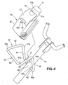
Fig. 4 is an exploded perspective view showing the handle post ofFig. 3 with the cylinder housing section removed therefrom; -
Fig. 5 is a top plan view illustrating the carrying handle ofFig. 4 ; -
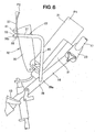
Fig. 6 is a view showing an example in which a cylinder cover ofFig. 2 is placed in an open position; -
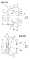
Fig. 7A is a view showing the walk-behind working machine being carried by two persons gripping the carrying handle; and -
Fig. 7B is a view showing the walk-behind working machine being carried by a single person gripping the carrying handle. - In the mode to be discussed below, a walk-behind tiller will be described as an example of the walk-behind working machine. However, the present invention should not be construed as being limited to the walk-behind tiller.
- The walk-behind working
machine 10 as shown inFig. 1 is comprised of agas engine 12 placed on an upper end part of a tiller body (working machine body) 11, afender 13 disposed below thegas engine 12, a plurality of tilling tines disposed below thefender 13 via atilling shaft 14, ahandle post 16 provided at arear part 11a of thetiller body 11, anoperating handle 17 disposed on thehandle post 16, a cylinder housing orretaining section 18, a cartridge-type gas cylinder 21 housed in thecylinder housing section 18, and acarrying handle 22 provided on thehandle post 16. - In the walk-behind
working machine 10, thegas engine 12 is driven by fuel in the gas cylinder orcartridge 21. The power produced by theengine 12 is transmitted to thetilling shaft 14 so that thetilling shaft 14 is rotated to till a soil with thetilling tines 15 while the machine runs with theoperating handle 17 gripped by an operator. - The
gas engine 12 is of the type which is driven by fuel gas supplied from the gas cylinder orcartridge 12. - As shown in
Figs. 2 and3 , thehandle post 16 comprises a tubular member extending rearwardly upwardly from a rear part of the working machine body. The operatinghandle 17 is supported on anupper end part 16a of thehandle post 16 via right and leftsupport brackets 23. Thecylinder housing section 18 is provided on anupper half 25 of thehandle post 16 in such a manner as to extend along thecylinder housing section 18. The carryinghandle 22 for carriage is provided on a generally centralperipheral wall section 26. - The operating
handle 17 comprises a tubular member formed into a U-shape as seen from a front side therefor, as shown inFig. 3 . The operatinghandle 17 has alower end part 17a mounted to theupper end part 16a of the handle post via the right and leftsupport brackets 23 and is provided at right and left upper orrear end parts 17b with right and leftgrips 27, 28 (seeFig. 1 ), respectively. - The
cylinder housing section 18 comprises a base 31 provided to extend along theupper half 25 of thehandle post 16 and acylinder cover 32 provided pivotally relative to thebase 31. - The
base 31 has a mouthpiece support part, not shown, for removably supporting a mouthpiece of thegas cylinder 21. By mounting the mouthpiece of thegas cylinder 21 to the mouthpiece support part, thegas cylinder 21 is placed to lie along theupper half 25 of thehandle post 16. - The
gas cylinder 21 comprises a commercially available gas cartridge filled with liquefied butane consisting chiefly of butane (hereinafter called "liquefied fuel gas"). Thegas cylinder 21 has a cylinder orcontainer body 34 with a jet nozzle protruding from the mouthpiece of thecontainer body 34, as shown inFig. 3 . By pressing the jet nozzle into thecontainer body 34, the liquefied fuel gas held inside thecontainer body 34 is lead out into asupply passage 35. - The
cylinder cover 32 is positioned between the gas cartridge orcylinder 21 and the carryinghandle 22 and capable of pivotal movement between a closed position P1 (Fig. 2 ) wherein thegas cylinder 21 is pressed against thebase 31 and an opened position P2 (seeFig. 6 ) wherein the gas cylinder mounting and removal are allowed. Thecylinder cover 32 is held in the closed position P1 in such an orientation as to lie along theupper half 25. - The
cylinder cover 32 comprises amain cover 36 pivotally provided to thebase 31, a sub-cover 37 pivotally mounted to adistal end 36a of themain cover 36, and a lockingpawl 38 provided on the sub-cover 37. - The
main cover 36 is configured such that it can be held in the closed position P1 by means of a spring member hot shown. By retaining themain cover 36 in the closed position P1, themain cover 36 brought into contact with thegas cylinder 21. As a result, thegas cylinder 21 is press-held by themain cover 36. - The sub-cover 37 is supported pivotally on a
distal end part 36a of themain cover 36 via asupport pin 41 and is configured to allow positioning in the closed position P1 via a spring member, not shown. Retaining the sub-cover 37 in the closed position P1 causes the sub-cover 37 to come into contact with thegas cylinder 21. As a result, the gas cylinder is held firmly by the sub-cover 37. - As the
main cover 36 is moved to the opened position P2 (Fig. 6 ) against the resiliency of the main cover spring member, not shown, and the sub-cover 37 is moved to the closed position P2 against the resiliency of the sub-cover spring member, not shown, the lockingpawl 38 is brought into locking engagement with the carryinghandle 22. As a result, themain cover 36 and the sub-cover 37 are held in the opened position P2. As themain cover 36 and the sub-cover 37 are thus opened, it becomes possible to hold thecovers handle 22 to thereby provide a suitable degree of opening of thecovers - By thus providing a suitable degree of opening of the
main cover 36 and the sub-cover 37, easy mounting and removal of thegas cylinder 21 is enabled. A mode of locking engagement of the lockingpawl 38 with the carryinghandle 22 will be discussed later with reference toFig. 6 . - As shown in
Figs. 4 and5 , the carryinghandle 22 is formed by integrally bending a tubular member. The carryinghandle 22 includes left and righthorizontal bases side wall parts peripheral wall 26 of thehandle post 16. The carryinghandle 22 also includes agrip 45 positioned upwardly of thecylinder cover 32. - Specifically, the carrying
handle 22 is comprised of the left and righthorizontal bases side wall parts left leg part 46 provided on the lefthorizontal base 43, aright leg part 47 provided on the righthorizontal base 44, and thegrip 45 provided on the left andright leg parts - The left
horizontal base 43 extends horizontally outwardly from the leftside wall part 26a. The lefthorizontal base 43 is positioned below thecylinder housing section 18, with itsouter end part 43a located outwardly of aleft side part 18a of thecylinder housing section 18. The righthorizontal base 44 is positioned coaxially with the lefthorizontal base 43 and extends horizontally outwardly from the rightside wall part 26b. The righthorizontal base 44 is positioned below thecylinder housing section 18, with itsouter end part 44a located externally of aright side part 18b of thecylinder housing section 18. The left and righthorizontal base - The
left leg part 46 extends upwardly from anouter end part 43a of the lefthorizontal base 43 and is positioned on theleft side part 18a of thecylinder housing section 18. Theright leg part 47 extends upwardly from anouter end part 44a of the righthorizontal base 44 and is positioned outwardly of theright side part 18b of thecylinder housing section 18. The left andright leg parts - The
grip 45 is provided on the respectiveupper end parts right leg parts grip 45 comprises left andright grip parts right leg parts central grip 53 provided between the left andright grip parts - The
left grip part 51 extends forwardly of the working machine from theupper end part 46a of theleft leg part 46 horizontally in such a manner as to be inclined gradually outwardly at an inclination angle of θ. Theright grip part 52 extends forwardly of the working machine from theupper end part 47a of theright leg part 47 horizontally in such a manner as to be inclined outwardly at an inclination angle of θ. In other words, the left andright grip parts upper end parts right leg parts - That is, the left and
right grip parts cylinder housing section 18 and are formed to diverge toward a forward direction of the working machine. Consequently, it is possible to provide a relatively large distance L between theleft grip part 51 and theright grip part 52. This permits two operators or attendants standing on left and right sides of the walk-behind workingmachine 10 to grip the respective left andright grip parts - In addition, with the
left grip part 52 arranged to extend in a forward direction of the working machine in such a manner as to be inclined an angle θ outwardly, it becomes possible for the operator standing on the left side of the walk-behind workingmachine 10 to easily grip and lift theleft grip part 51 with his right hand. On the other hand, with theright grip part 52 arranged to extend in a forward direction of the walk-behind workingmachine 10 in such a manner as to be inclined an angle θ outwardly, it is possible for the operator standing on the right side of the walk-behind workingmachine 10 to easily grip and lift theright grip part 52 with his left hand. - The
central grip part 53 is provided between afront end part 51a of theleft grip part 51 and afront end part 52a of theright grip part 52 and extends horizontally transversely of the machine. Thecentral grip part 53 is positioned below thecylinder housing section 18. Similarly to the distance L, by arranging the left andright grip parts - With the
central grip part 52 thus arranged to have a relatively large length, thecentral grip part 53 can be easily gripped (lifted). - As explained above, the carrying
handle 22 includes the left and righthorizontal bases side wall parts peripheral wall part 26, the left and righthorizontal bases cylinder housing section 18, the left andright leg parts cylinder housing section 18, and thegrip 45 provided above thecylinder housing section 18. - The carrying
handle 22 is thus formed to surround the gas cylinder orcartridge 21. By providing the carryinghandle 22 to thus surround thegas cylinder 21, it becomes possible to dispose both thecylinder housing section 18 and the carryinghandle 22 on thehandle post 16. - The carrying
handle 22 for transportation use is provided with thegrip 45. This makes it possible to grip thegrip 45 and lift and transport the walk-behind workingmachine 10. - Note also that the carrying
handle 22 includes the left and righthorizontal bases right grip parts central drip part 53, which are arranged to surround the cylinder housing section 18 (and hence the gas cartridge 21). As a result, the gas cylinder is protected by the carryinghandle 22. - Next, discussion will be made as to an operation for retaining the
cylinder cover 32 in the opened position P2, with reference toFig. 6 . - The
main cover 36 is moved to the opened position P2 against the resiliency of the main-cover spring member (not shown), followed by moving the sub-cover 37 to the opened position P2 against the resiliency of the sub-cover spring member (not shown). Themain cover 36 is brought into contact with thecentral grip part 53 of the carryinghandle 22. This places themain cover 36 and the sub-cover 37 in an appropriate degree of opening. - Further, when the
main cover 36 is brought into contact with thecentral grip part 53 of the carryinghandle 22, thedistal end 38a of the lockingpawl 38 is elastically deformed to lockingly engage with thecentral grip part 53. Themain cover 36 and the sub-cover 37 are thus maintained in the opened position P2. Themain cover 36 and the sub-cover 37 are thus kept in the appropriately opened position, thereby allowing easy loading and unloading of thegas cartridge 21. - To unlock the
distal end 38a of the lockingpawl 38 from thecentral grip part 53, the sub-cover 37 is moved in a counter-clockwise direction about thesupport pin 41. Then, the distal ortop end 38a of the lockingpawl 38 moves downward to cause thetop end 38a to be released from thecentral grip part 53, whereby themain cover 36 becomes capable of moving toward the closed position P1 by the resilient force of the main cover spring, not shown. - Referring now to
Figs. 7A and 7B , discussion will be made as to shipping of the walk-behind workingmachine 10 by using the carryinghandle 22.Fig. 7A illustrates the walk-behind workingmachine 10 being carried by the two attendants standing on the left and right sides of the machine, whilstFig. 7B illustrates the workingmachine 10 being carried by a single attendant. - As shown in
Fig. 7A and discussed above, the space L left between theleft grip part 51 and theright grip part 52 is relatively large. This enables a carryingattendant 61 standing on the left side of the walk-behind workingmachine 10 to grip theleft grip part 51 and a carryingattendant 62 standing on the right side of the working machine to grip theright grip part 52 without being interfered one by another. - The
left grip part 51 extends in the forward direction of the working machine in such a manner as to be inclined outwardly at the inclination angle of θ (Fig. 5 ). As theleft carrying attendant 61 grips theleft grip part 51 with hisright hand 61a, the back 61b of hisright hand 61a leans forward in correspondence with theleft grip part 51. Consequently, theright hand 61a is placed in the posture that makes it easier to lift theleft grip part 51 compared to the case wherein the back 61b of theright hand 61a is laterally oriented (that is, when theleft grip part 51 is positioned parallel to the handle post 16). The leftside carrying attendant 61 can thus easily lift theleft grip part 51 with hisright hand 61a. - Similarly to the
left grip part 51, theright grip part 52 extends toward the forward direction of the working machine in an outwardly inclined manner at the inclined angle of θ (Fig. 5 ). When the right-handside carrying attendant 62 grips theright grip part 52 with hisleft hand 62a, the back 62b of theleft hand 62a leans forward in correspondence with theright grip part 52. Thus, theleft hand 62 is placed in the posture that makes it easier to lift theright grip part 52, compared to the case wherein the back 62b of theleft hand 62a is placed in lateral orientation (that is, when theright grip part 52 lies parallel to the handle post 16). The right-handside carrying attendant 62 can thus easily lift theright grip part 52 with hisleft hand 62a. - With the left and
right grip parts Fig. 5 ), the left- and right-hand side carrying attendants can easily grip the respective left andright grip parts Fig. 1 ) to a desired location. - As shown in
Fig. 7B , the left andright grip parts central grip part 53 to have a relatively large length. This makes it easy for, e.g., left-handside carrying attendant 61 to grip or lift thecentral grip part 53 with hisright hand 61a. The walk-behind working machine 10 (Fig. 1 ) can thus be carried by a single carrying attendant and is imparted with increased mobility. - The carrying
handle 22, thecylinder cover 32, thegrip 45, the left andright grip parts central grip part 53 have been described in the present embodiment as examples only and the invention should not be construed as being limited thereto because changes and modifications are possible within the scope defined in the claims. - The present invention is particularly useful for application to a walk-behind working machine wherein a gas cartridge is placed along a handle post and an engine is driven by the fuel fed from the gas cartridge.
-
- 10...walk-behind working machine; 11...working machine body; 11a...rear part of the working machine body; 12... gas engine; 16... handle post;
- 21...cartridge-type gas cylinder; 21a, 21b...left and right side parts of the gas cartridge; 22...carrying handle; 32...cylinder cover; 45... grip; 51...left grip part;
- 52...right grip part; and 53...central grip part
Claims (4)
- A walk-behind working machine comprising:a working machine body (11);a handle post (16) extending rearwardly upwardly from a rear part of the working machine body;a cartridge-type gas cylinder (21) disposed to lie along a length of the handle post;a gas engine (12) capable of being driven by fuel contained in the cartridge-type gas cylinder; and characterized in that the machine comprisesa carrying handle (22) disposed on the handle post and having a grip (45) formed to surround the cartridge-type gas cylinder.
- The walk-behind working machine of claim 1, further comprising a cylinder cover (32) disposed between the cartridge-type gas cylinder and the carrying handle for holding the cartridge-type gas cylinder and being capable of opening and closing actions.
- The walk-behind working machine of claim 1, wherein the grip (45) comprises left and right grip parts (51, 52) extending in a forward direction of the working machine from positions on left and right sides of the cartridge-type gas cylinder in a gradually converging fashion.
- The walk-behind working machine of claim 3, wherein the grip (45) comprises a central grip part (53) extending between front end parts (51a, 52a) of the left and right grip parts (51, 52).
Applications Claiming Priority (2)
| Application Number | Priority Date | Filing Date | Title |
|---|---|---|---|
| JP2008121192A JP4951584B2 (en) | 2008-05-07 | 2008-05-07 | Walking type work machine |
| PCT/JP2009/056955 WO2009136527A1 (en) | 2008-05-07 | 2009-04-03 | Walking-type working machine |
Publications (3)
| Publication Number | Publication Date |
|---|---|
| EP2277366A1 EP2277366A1 (en) | 2011-01-26 |
| EP2277366A4 EP2277366A4 (en) | 2011-06-08 |
| EP2277366B1 true EP2277366B1 (en) | 2012-11-28 |
Family
ID=41264584
Family Applications (1)
| Application Number | Title | Priority Date | Filing Date |
|---|---|---|---|
| EP09742652A Not-in-force EP2277366B1 (en) | 2008-05-07 | 2009-04-03 | Walking-type working machine |
Country Status (7)
| Country | Link |
|---|---|
| US (1) | US8191659B2 (en) |
| EP (1) | EP2277366B1 (en) |
| JP (1) | JP4951584B2 (en) |
| KR (1) | KR101184510B1 (en) |
| CN (1) | CN102014606B (en) |
| ES (1) | ES2399316T3 (en) |
| WO (1) | WO2009136527A1 (en) |
Families Citing this family (4)
| Publication number | Priority date | Publication date | Assignee | Title |
|---|---|---|---|---|
| JP4802237B2 (en) * | 2008-11-26 | 2011-10-26 | 本田技研工業株式会社 | Cassette gas cylinder mounting structure |
| US9167737B2 (en) * | 2013-05-22 | 2015-10-27 | Carts & Tools Technology, Inc. | Garden implement |
| KR200489768Y1 (en) | 2018-06-18 | 2019-10-21 | 이범규 | Power Train for Walking Type Working Machine |
| KR102353595B1 (en) | 2021-06-09 | 2022-01-20 | 이범규 | A direction change device for a walking type work machine that works by transmitting power in a direct gear method |
Family Cites Families (19)
| Publication number | Priority date | Publication date | Assignee | Title |
|---|---|---|---|---|
| BE666203A (en) * | 1964-06-30 | |||
| US3452460A (en) * | 1966-10-31 | 1969-07-01 | Roper Corp | Impeller for rotary snow removal apparatus |
| US4255880A (en) * | 1979-06-25 | 1981-03-17 | Berkley And Company, Inc. | Portable rotary snow thrower |
| US5603173A (en) * | 1994-01-28 | 1997-02-18 | Ryobi Outdoor Products Inc. | Snow thrower |
| US5735064A (en) * | 1996-05-21 | 1998-04-07 | Holl; Trygve A. | Operational control mechanism |
| US5771582A (en) * | 1996-07-26 | 1998-06-30 | Wci Outdoor Products, Inc. | Apparatus for carrying spare line spool on flexible line trimmer |
| JPH10131809A (en) * | 1996-10-30 | 1998-05-19 | Honda Motor Co Ltd | Gas engine and gas engine working machine |
| US5850882A (en) * | 1997-03-28 | 1998-12-22 | Link; Cletus H. | Garden power tool |
| JPH11170876A (en) * | 1997-12-12 | 1999-06-29 | Yanmar Agricult Equip Co Ltd | Control machine |
| JPH11243701A (en) * | 1998-03-04 | 1999-09-14 | Nikkari Co Ltd | Soil management machine |
| JP2001322572A (en) | 2000-05-17 | 2001-11-20 | Mitsubishi Agricult Mach Co Ltd | Walking type moving agricultural machine |
| CA2351863C (en) * | 2000-07-12 | 2005-08-09 | Honda Giken Kogyo Kabushiki Kaisha | Snow removing machine |
| JP2002272202A (en) | 2001-03-16 | 2002-09-24 | Iseki & Co Ltd | Wheel shaft type rotary plowing machine |
| JP4556370B2 (en) | 2001-09-19 | 2010-10-06 | 井関農機株式会社 | Walking type tillage device |
| JP2003225001A (en) * | 2003-01-30 | 2003-08-12 | Iseki & Co Ltd | Walking type tilling apparatus |
| JP2007097442A (en) | 2005-09-30 | 2007-04-19 | Iseki & Co Ltd | Walking-type tiller |
| JP4700516B2 (en) | 2006-02-21 | 2011-06-15 | 株式会社クボタ | Walking type work machine |
| CN1914984B (en) * | 2006-09-01 | 2010-04-07 | 中国农业大学 | Lawn machine with new fuel cell |
| US7926599B2 (en) * | 2008-06-23 | 2011-04-19 | Meydrive, Llc | Motorized barrel cart |
-
2008
- 2008-05-07 JP JP2008121192A patent/JP4951584B2/en active Active
-
2009
- 2009-04-03 EP EP09742652A patent/EP2277366B1/en not_active Not-in-force
- 2009-04-03 CN CN200980115836.3A patent/CN102014606B/en not_active Expired - Fee Related
- 2009-04-03 KR KR1020107025900A patent/KR101184510B1/en active IP Right Grant
- 2009-04-03 WO PCT/JP2009/056955 patent/WO2009136527A1/en active Application Filing
- 2009-04-03 ES ES09742652T patent/ES2399316T3/en active Active
- 2009-04-03 US US12/991,306 patent/US8191659B2/en active Active
Also Published As
| Publication number | Publication date |
|---|---|
| WO2009136527A1 (en) | 2009-11-12 |
| US20110048818A1 (en) | 2011-03-03 |
| KR20110008249A (en) | 2011-01-26 |
| EP2277366A1 (en) | 2011-01-26 |
| JP4951584B2 (en) | 2012-06-13 |
| KR101184510B1 (en) | 2012-09-19 |
| EP2277366A4 (en) | 2011-06-08 |
| ES2399316T3 (en) | 2013-03-27 |
| US8191659B2 (en) | 2012-06-05 |
| JP2009268401A (en) | 2009-11-19 |
| CN102014606A (en) | 2011-04-13 |
| CN102014606B (en) | 2013-01-02 |
Similar Documents
| Publication | Publication Date | Title |
|---|---|---|
| EP2277366B1 (en) | Walking-type working machine | |
| US7176411B2 (en) | Wire feeder | |
| JP5614047B2 (en) | Electric motorcycle | |
| US10384562B1 (en) | Battery box structure of electric vehicle | |
| JP5988623B2 (en) | Motorcycle | |
| JP2010179690A (en) | Article storage structure for motorcycle | |
| JP4864859B2 (en) | Gas engine mounted work machine | |
| US20150298311A1 (en) | Manually guided, petrol-powered implement | |
| CN101468600B (en) | Gas canister retaining structure for gas-engine-mounted working machine | |
| JP5690601B2 (en) | Work vehicle | |
| EP3964431B1 (en) | Straddled vehicle | |
| JP2020079067A (en) | Saddle-riding type electric vehicle | |
| JP2009091091A (en) | Battery hood of cargo handling vehicle | |
| US20090127009A1 (en) | Handle structure of walk-behind working machine | |
| JP2020080289A (en) | Battery and battery-equipped device | |
| JPH0281781A (en) | Motorcycle | |
| JP5642571B2 (en) | Work vehicle | |
| JP4789909B2 (en) | Gas engine mounted work machine | |
| WO2023119494A1 (en) | Saddled vehicle and article support mechanism | |
| JP5363210B2 (en) | Back negative power sprayer | |
| JPH0528994Y2 (en) | ||
| JP2004000248A (en) | Combine | |
| JP2016034283A (en) | Walking type work machine | |
| JP5866252B2 (en) | Work vehicle | |
| JP2003327395A (en) | Cargo handling vehicle |
Legal Events
| Date | Code | Title | Description |
|---|---|---|---|
| PUAI | Public reference made under article 153(3) epc to a published international application that has entered the european phase |
Free format text: ORIGINAL CODE: 0009012 |
|
| 17P | Request for examination filed |
Effective date: 20101118 |
|
| AK | Designated contracting states |
Kind code of ref document: A1 Designated state(s): AT BE BG CH CY CZ DE DK EE ES FI FR GB GR HR HU IE IS IT LI LT LU LV MC MK MT NL NO PL PT RO SE SI SK TR |
|
| AX | Request for extension of the european patent |
Extension state: AL BA RS |
|
| A4 | Supplementary search report drawn up and despatched |
Effective date: 20110506 |
|
| DAX | Request for extension of the european patent (deleted) | ||
| GRAP | Despatch of communication of intention to grant a patent |
Free format text: ORIGINAL CODE: EPIDOSNIGR1 |
|
| RIN1 | Information on inventor provided before grant (corrected) |
Inventor name: ITO, TOMOKI C/O HONDA R&D CO., LTD. Inventor name: KOBAYASHI, HIDEAKI C/O HONDA R&D CO., LTD. |
|
| GRAS | Grant fee paid |
Free format text: ORIGINAL CODE: EPIDOSNIGR3 |
|
| GRAA | (expected) grant |
Free format text: ORIGINAL CODE: 0009210 |
|
| AK | Designated contracting states |
Kind code of ref document: B1 Designated state(s): AT BE BG CH CY CZ DE DK EE ES FI FR GB GR HR HU IE IS IT LI LT LU LV MC MK MT NL NO PL PT RO SE SI SK TR |
|
| REG | Reference to a national code |
Ref country code: GB Ref legal event code: FG4D |
|
| REG | Reference to a national code |
Ref country code: CH Ref legal event code: EP |
|
| REG | Reference to a national code |
Ref country code: AT Ref legal event code: REF Ref document number: 585641 Country of ref document: AT Kind code of ref document: T Effective date: 20121215 |
|
| REG | Reference to a national code |
Ref country code: IE Ref legal event code: FG4D |
|
| REG | Reference to a national code |
Ref country code: DE Ref legal event code: R096 Ref document number: 602009011551 Country of ref document: DE Effective date: 20130117 |
|
| REG | Reference to a national code |
Ref country code: ES Ref legal event code: FG2A Ref document number: 2399316 Country of ref document: ES Kind code of ref document: T3 Effective date: 20130327 |
|
| REG | Reference to a national code |
Ref country code: AT Ref legal event code: MK05 Ref document number: 585641 Country of ref document: AT Kind code of ref document: T Effective date: 20121128 |
|
| REG | Reference to a national code |
Ref country code: NL Ref legal event code: VDEP Effective date: 20121128 |
|
| REG | Reference to a national code |
Ref country code: LT Ref legal event code: MG4D |
|
| PG25 | Lapsed in a contracting state [announced via postgrant information from national office to epo] |
Ref country code: FI Free format text: LAPSE BECAUSE OF FAILURE TO SUBMIT A TRANSLATION OF THE DESCRIPTION OR TO PAY THE FEE WITHIN THE PRESCRIBED TIME-LIMIT Effective date: 20121128 Ref country code: LT Free format text: LAPSE BECAUSE OF FAILURE TO SUBMIT A TRANSLATION OF THE DESCRIPTION OR TO PAY THE FEE WITHIN THE PRESCRIBED TIME-LIMIT Effective date: 20121128 Ref country code: NO Free format text: LAPSE BECAUSE OF FAILURE TO SUBMIT A TRANSLATION OF THE DESCRIPTION OR TO PAY THE FEE WITHIN THE PRESCRIBED TIME-LIMIT Effective date: 20130228 Ref country code: SE Free format text: LAPSE BECAUSE OF FAILURE TO SUBMIT A TRANSLATION OF THE DESCRIPTION OR TO PAY THE FEE WITHIN THE PRESCRIBED TIME-LIMIT Effective date: 20121128 |
|
| PG25 | Lapsed in a contracting state [announced via postgrant information from national office to epo] |
Ref country code: LV Free format text: LAPSE BECAUSE OF FAILURE TO SUBMIT A TRANSLATION OF THE DESCRIPTION OR TO PAY THE FEE WITHIN THE PRESCRIBED TIME-LIMIT Effective date: 20121128 Ref country code: GR Free format text: LAPSE BECAUSE OF FAILURE TO SUBMIT A TRANSLATION OF THE DESCRIPTION OR TO PAY THE FEE WITHIN THE PRESCRIBED TIME-LIMIT Effective date: 20130301 Ref country code: PL Free format text: LAPSE BECAUSE OF FAILURE TO SUBMIT A TRANSLATION OF THE DESCRIPTION OR TO PAY THE FEE WITHIN THE PRESCRIBED TIME-LIMIT Effective date: 20121128 Ref country code: PT Free format text: LAPSE BECAUSE OF FAILURE TO SUBMIT A TRANSLATION OF THE DESCRIPTION OR TO PAY THE FEE WITHIN THE PRESCRIBED TIME-LIMIT Effective date: 20130328 Ref country code: SI Free format text: LAPSE BECAUSE OF FAILURE TO SUBMIT A TRANSLATION OF THE DESCRIPTION OR TO PAY THE FEE WITHIN THE PRESCRIBED TIME-LIMIT Effective date: 20121128 Ref country code: BE Free format text: LAPSE BECAUSE OF FAILURE TO SUBMIT A TRANSLATION OF THE DESCRIPTION OR TO PAY THE FEE WITHIN THE PRESCRIBED TIME-LIMIT Effective date: 20121128 |
|
| PG25 | Lapsed in a contracting state [announced via postgrant information from national office to epo] |
Ref country code: AT Free format text: LAPSE BECAUSE OF FAILURE TO SUBMIT A TRANSLATION OF THE DESCRIPTION OR TO PAY THE FEE WITHIN THE PRESCRIBED TIME-LIMIT Effective date: 20121128 |
|
| PG25 | Lapsed in a contracting state [announced via postgrant information from national office to epo] |
Ref country code: BG Free format text: LAPSE BECAUSE OF FAILURE TO SUBMIT A TRANSLATION OF THE DESCRIPTION OR TO PAY THE FEE WITHIN THE PRESCRIBED TIME-LIMIT Effective date: 20130228 Ref country code: CZ Free format text: LAPSE BECAUSE OF FAILURE TO SUBMIT A TRANSLATION OF THE DESCRIPTION OR TO PAY THE FEE WITHIN THE PRESCRIBED TIME-LIMIT Effective date: 20121128 Ref country code: SK Free format text: LAPSE BECAUSE OF FAILURE TO SUBMIT A TRANSLATION OF THE DESCRIPTION OR TO PAY THE FEE WITHIN THE PRESCRIBED TIME-LIMIT Effective date: 20121128 Ref country code: EE Free format text: LAPSE BECAUSE OF FAILURE TO SUBMIT A TRANSLATION OF THE DESCRIPTION OR TO PAY THE FEE WITHIN THE PRESCRIBED TIME-LIMIT Effective date: 20121128 Ref country code: DK Free format text: LAPSE BECAUSE OF FAILURE TO SUBMIT A TRANSLATION OF THE DESCRIPTION OR TO PAY THE FEE WITHIN THE PRESCRIBED TIME-LIMIT Effective date: 20121128 |
|
| PG25 | Lapsed in a contracting state [announced via postgrant information from national office to epo] |
Ref country code: RO Free format text: LAPSE BECAUSE OF FAILURE TO SUBMIT A TRANSLATION OF THE DESCRIPTION OR TO PAY THE FEE WITHIN THE PRESCRIBED TIME-LIMIT Effective date: 20121128 Ref country code: NL Free format text: LAPSE BECAUSE OF FAILURE TO SUBMIT A TRANSLATION OF THE DESCRIPTION OR TO PAY THE FEE WITHIN THE PRESCRIBED TIME-LIMIT Effective date: 20121128 |
|
| PLBE | No opposition filed within time limit |
Free format text: ORIGINAL CODE: 0009261 |
|
| STAA | Information on the status of an ep patent application or granted ep patent |
Free format text: STATUS: NO OPPOSITION FILED WITHIN TIME LIMIT |
|
| 26N | No opposition filed |
Effective date: 20130829 |
|
| PG25 | Lapsed in a contracting state [announced via postgrant information from national office to epo] |
Ref country code: MC Free format text: LAPSE BECAUSE OF FAILURE TO SUBMIT A TRANSLATION OF THE DESCRIPTION OR TO PAY THE FEE WITHIN THE PRESCRIBED TIME-LIMIT Effective date: 20121128 Ref country code: CY Free format text: LAPSE BECAUSE OF FAILURE TO SUBMIT A TRANSLATION OF THE DESCRIPTION OR TO PAY THE FEE WITHIN THE PRESCRIBED TIME-LIMIT Effective date: 20121128 |
|
| REG | Reference to a national code |
Ref country code: CH Ref legal event code: PL |
|
| REG | Reference to a national code |
Ref country code: DE Ref legal event code: R097 Ref document number: 602009011551 Country of ref document: DE Effective date: 20130829 |
|
| REG | Reference to a national code |
Ref country code: IE Ref legal event code: MM4A |
|
| PG25 | Lapsed in a contracting state [announced via postgrant information from national office to epo] |
Ref country code: LI Free format text: LAPSE BECAUSE OF NON-PAYMENT OF DUE FEES Effective date: 20130430 Ref country code: HR Free format text: LAPSE BECAUSE OF FAILURE TO SUBMIT A TRANSLATION OF THE DESCRIPTION OR TO PAY THE FEE WITHIN THE PRESCRIBED TIME-LIMIT Effective date: 20130731 Ref country code: CH Free format text: LAPSE BECAUSE OF NON-PAYMENT OF DUE FEES Effective date: 20130430 |
|
| PG25 | Lapsed in a contracting state [announced via postgrant information from national office to epo] |
Ref country code: IE Free format text: LAPSE BECAUSE OF NON-PAYMENT OF DUE FEES Effective date: 20130403 |
|
| PG25 | Lapsed in a contracting state [announced via postgrant information from national office to epo] |
Ref country code: MT Free format text: LAPSE BECAUSE OF FAILURE TO SUBMIT A TRANSLATION OF THE DESCRIPTION OR TO PAY THE FEE WITHIN THE PRESCRIBED TIME-LIMIT Effective date: 20121128 |
|
| PG25 | Lapsed in a contracting state [announced via postgrant information from national office to epo] |
Ref country code: TR Free format text: LAPSE BECAUSE OF FAILURE TO SUBMIT A TRANSLATION OF THE DESCRIPTION OR TO PAY THE FEE WITHIN THE PRESCRIBED TIME-LIMIT Effective date: 20121128 |
|
| PG25 | Lapsed in a contracting state [announced via postgrant information from national office to epo] |
Ref country code: HU Free format text: LAPSE BECAUSE OF FAILURE TO SUBMIT A TRANSLATION OF THE DESCRIPTION OR TO PAY THE FEE WITHIN THE PRESCRIBED TIME-LIMIT; INVALID AB INITIO Effective date: 20090403 Ref country code: MK Free format text: LAPSE BECAUSE OF FAILURE TO SUBMIT A TRANSLATION OF THE DESCRIPTION OR TO PAY THE FEE WITHIN THE PRESCRIBED TIME-LIMIT Effective date: 20121128 Ref country code: LU Free format text: LAPSE BECAUSE OF NON-PAYMENT OF DUE FEES Effective date: 20130403 |
|
| REG | Reference to a national code |
Ref country code: FR Ref legal event code: PLFP Year of fee payment: 8 |
|
| PG25 | Lapsed in a contracting state [announced via postgrant information from national office to epo] |
Ref country code: IS Free format text: LAPSE BECAUSE OF FAILURE TO SUBMIT A TRANSLATION OF THE DESCRIPTION OR TO PAY THE FEE WITHIN THE PRESCRIBED TIME-LIMIT Effective date: 20121128 |
|
| REG | Reference to a national code |
Ref country code: FR Ref legal event code: PLFP Year of fee payment: 9 |
|
| REG | Reference to a national code |
Ref country code: FR Ref legal event code: PLFP Year of fee payment: 10 |
|
| PGFP | Annual fee paid to national office [announced via postgrant information from national office to epo] |
Ref country code: IT Payment date: 20190419 Year of fee payment: 11 Ref country code: ES Payment date: 20190503 Year of fee payment: 11 |
|
| REG | Reference to a national code |
Ref country code: DE Ref legal event code: R084 Ref document number: 602009011551 Country of ref document: DE |
|
| REG | Reference to a national code |
Ref country code: GB Ref legal event code: 746 Effective date: 20191218 |
|
| PGFP | Annual fee paid to national office [announced via postgrant information from national office to epo] |
Ref country code: GB Payment date: 20200325 Year of fee payment: 12 |
|
| PGFP | Annual fee paid to national office [announced via postgrant information from national office to epo] |
Ref country code: FR Payment date: 20200312 Year of fee payment: 12 |
|
| REG | Reference to a national code |
Ref country code: DE Ref legal event code: R082 Ref document number: 602009011551 Country of ref document: DE |
|
| PGFP | Annual fee paid to national office [announced via postgrant information from national office to epo] |
Ref country code: DE Payment date: 20210316 Year of fee payment: 13 |
|
| REG | Reference to a national code |
Ref country code: ES Ref legal event code: FD2A Effective date: 20210830 |
|
| PG25 | Lapsed in a contracting state [announced via postgrant information from national office to epo] |
Ref country code: IT Free format text: LAPSE BECAUSE OF NON-PAYMENT OF DUE FEES Effective date: 20200403 |
|
| PG25 | Lapsed in a contracting state [announced via postgrant information from national office to epo] |
Ref country code: ES Free format text: LAPSE BECAUSE OF NON-PAYMENT OF DUE FEES Effective date: 20200404 |
|
| GBPC | Gb: european patent ceased through non-payment of renewal fee |
Effective date: 20210403 |
|
| PG25 | Lapsed in a contracting state [announced via postgrant information from national office to epo] |
Ref country code: GB Free format text: LAPSE BECAUSE OF NON-PAYMENT OF DUE FEES Effective date: 20210403 Ref country code: FR Free format text: LAPSE BECAUSE OF NON-PAYMENT OF DUE FEES Effective date: 20210430 |
|
| REG | Reference to a national code |
Ref country code: DE Ref legal event code: R119 Ref document number: 602009011551 Country of ref document: DE |
|
| PG25 | Lapsed in a contracting state [announced via postgrant information from national office to epo] |
Ref country code: DE Free format text: LAPSE BECAUSE OF NON-PAYMENT OF DUE FEES Effective date: 20221103 |